

Samsung GT-C3530 Schematics
GSM TELEPHONE
GT-C3530
GSM TELEPHONE
CONTENTS
Safety Precautions
1.
Specification
2.
Product Function
3.
Exploded View and Parts list
4.
MAIN Electrical Parts List
5.
Level1Repair
6.
Disassembly and Assembly
7.
Instructions
Chart of Troubleshooting
8.
Reference data
9.
Notice
All functionality, features, specifications and other
product information provided in this document inclu
ding, but not limited to, the benefits, design, pricing,
components, performance, availability, and capabiliti
es of the product are subject to change without
-
notice or obligation. Samsung reserves the right to
make changes to this document and the product
described herein, at anytime, without obligation on
Samsung to provide notification of such change.
:
GSPN(Global Service Partner Network)
Country Web Site
North America service.samsungportal.com
Latin America latin.samsungportal.com
CIS cis.samsungportal.com
Europe europe.samsungportal.com
China china.samsungportal.com
Asia asia.samsungportal.com
Mideast&Africa mea.samsungportal.com
This Service Manual isaproperty of Samsung Electronics Co.,Ltd.
Any unauthorized use of Manual can be punished under applicable
International and/or domestic law.
Samsung Electronics Co.,Ltd.
ⓒ
2010. 10.
Rev.1.0
Level
8.
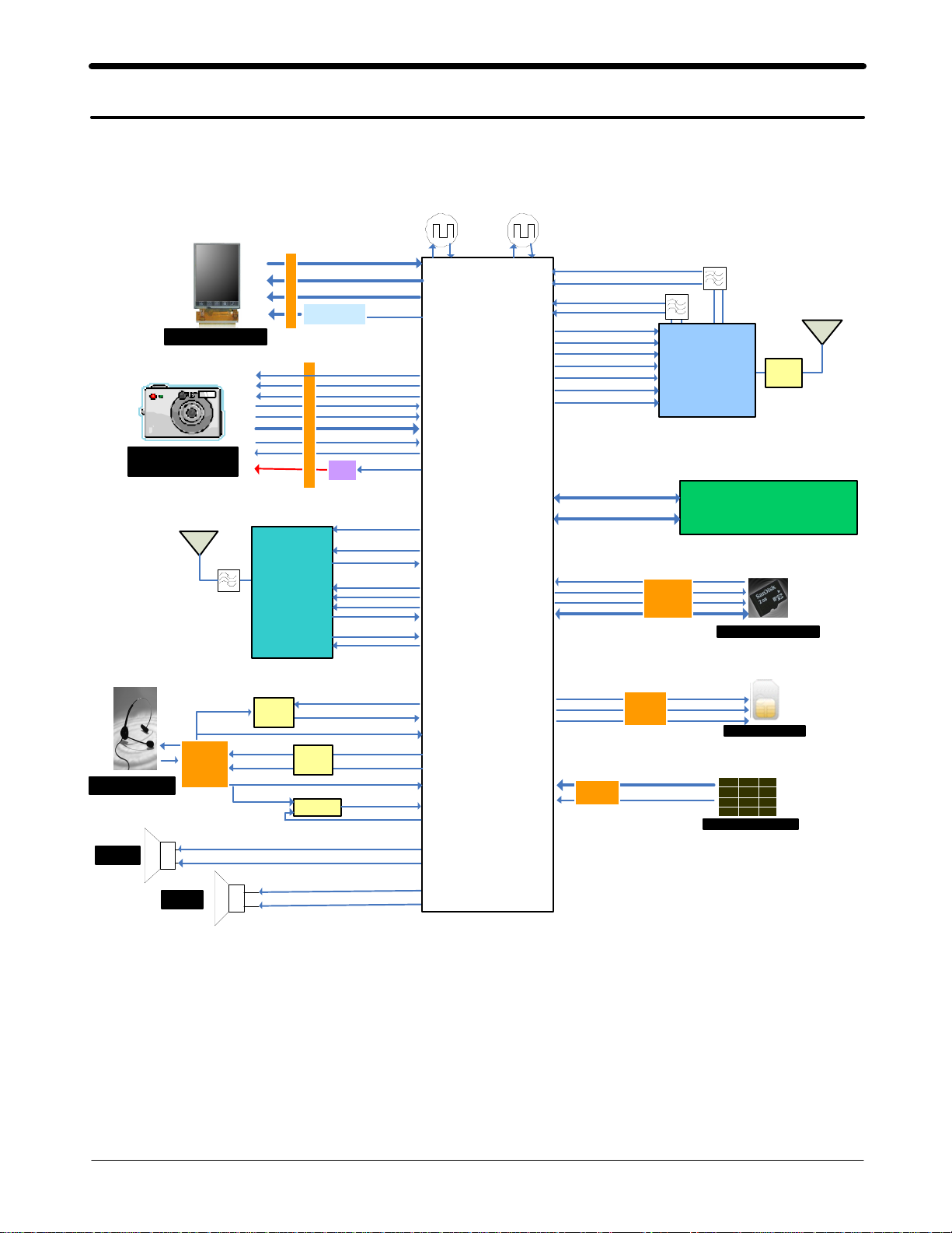
Block Diagram
8-1.
Repair
3
LCD Module
3 ME GA
CAM Module
BT ANT
SAW
LCD_CON
BT
BC63B239A04
FLM,LCD_RST
LCD _RS,C S,W R,R D
LCD _D(0:7)
BA CKLI GHT
DRIVER
CAM_DATA(0:7)
CAM _PC LK_IN
CA M _ C O N
CAM_M CLK_OUT
CAM
LDO
CLK26M_BT
BT_ REQ _CL K
PCM _S YNC
PCM _RX D
UART2_TXD
UART2_RXD
EN_LC D_B L
CAM_SCL
CAM _SD A
CAM_RS T
CAM_HSYN C
CAM_VSYNC
EN _C AM_PW R
BT _RST
PCM_C LK
PCM_T XD
26MHz
TCXO
RTC
Base Band
Catfish213
PMB8810
32.736KHz
DCS1800_RX
PC S1 9 00_ R X
GSM850_R X
GSM9 00_RX
DETECT _SD
SD_CMD
SD_C LK
SD_D ATA (0:3)
BS1
BS2
TX_EN
VL OGI C
RAMP
LB _T X
HB_TX
AD( 0:1 5 )
A(16:26)
SAW
SAW
2G PAM
SWITCH
Module
RF7161
256 NOR/1G On e N a n d /256 UtRAM
T-F LA SH
Socket
MEMORY
KAP 202N00 M-B WEW
T-FLA SH Card
Main ANT
RF
SW
EAR PHONE
SPK
FM_ANT_EAR
3.5pi
Socket
RCV
FM
LNA
EAR _3.5_L
EAR _3.5_R
EAR _MIC_P
SE N D_ EN D
FM_LNA_SW
FM_LNA_OUT
3.5_ CON_D ETE CT
EA R
AMP
COMP
EA R _ S PK _ L
EAR_SPK_R
EAR _SW
SEN D_END_DIRECT
SPK _P
SP K_N
RCV_N
RCV_P
SI M_R ST
SIM_C LK
SI M _I O
MAINKEY
CON
SI M
So ck et
KEY_COL(0:4)
KEY_ROW(0:4)
ONKEY_ N
SI M Card
1 2 3
4 5 6
7 8 9
* 0 #
Main Key
8-1
SAMSUNG Proprietary-Contents may change without notice
This Document can not be used without Samsung's authorization
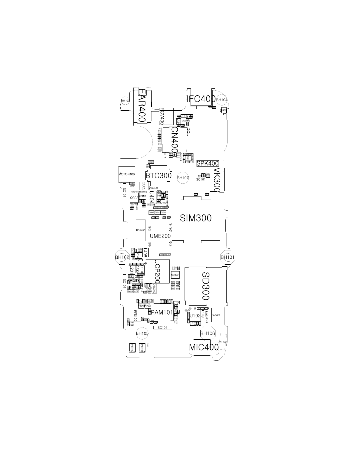
Level3Repair
PCB Diagrams
8-2.
8-2-1.
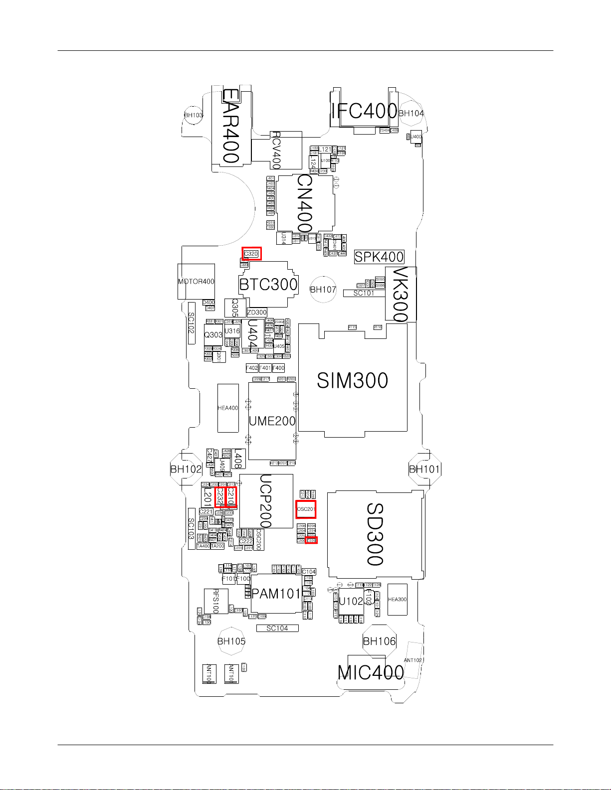
Top
8-2
SAMSUNG Proprietary-Contents may change without notice
This Document can not be used without Samsung's authorization
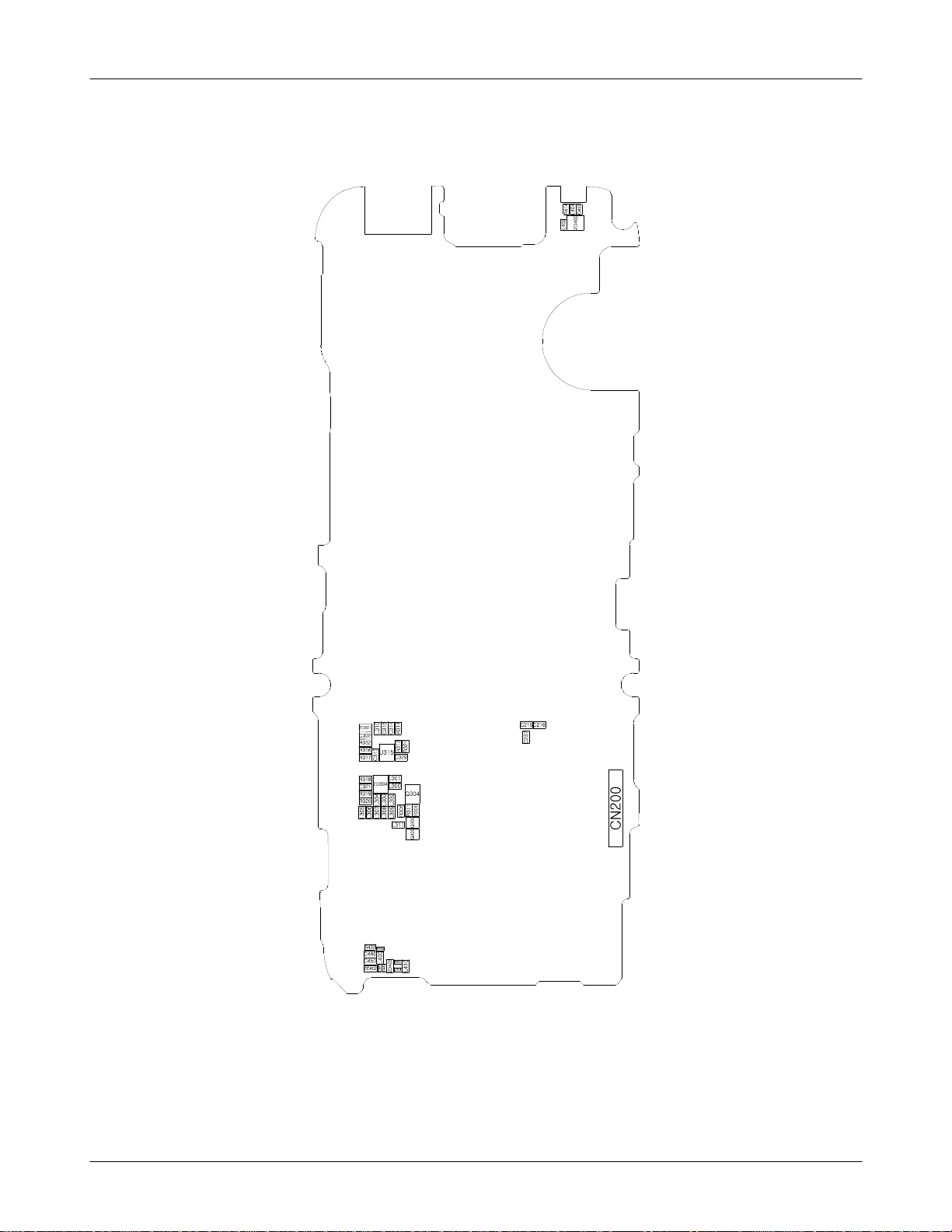
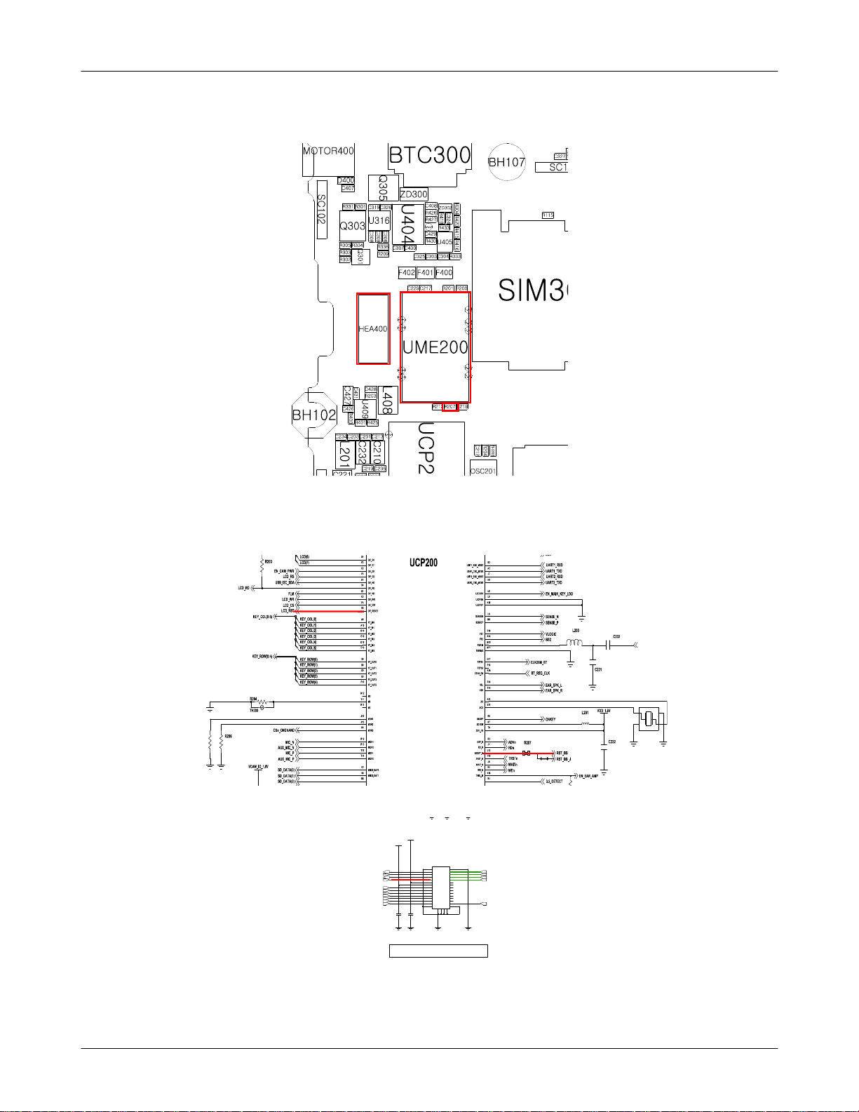
Level3Repair
8-2-1.
Bottom
8-3
SAMSUNG Proprietary-Contents may change without notice
This Document can not be used without Samsung's authorization
Level3Repair
Flow Chart of Troubleshooting
8-3.
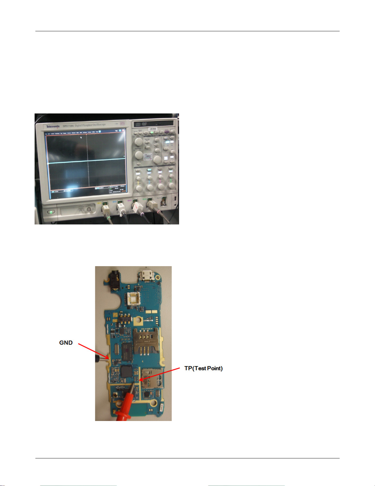
presetting methods for checking TP
(
GND&TP(exp. VBAT=
-
look over the coming out signal.
-
C210, C210,
C320
using Oscilloscope
)
Oscilloscope
8-4
SAMSUNG Proprietary-Contents may change without notice
This Document can not be used without Samsung's authorization
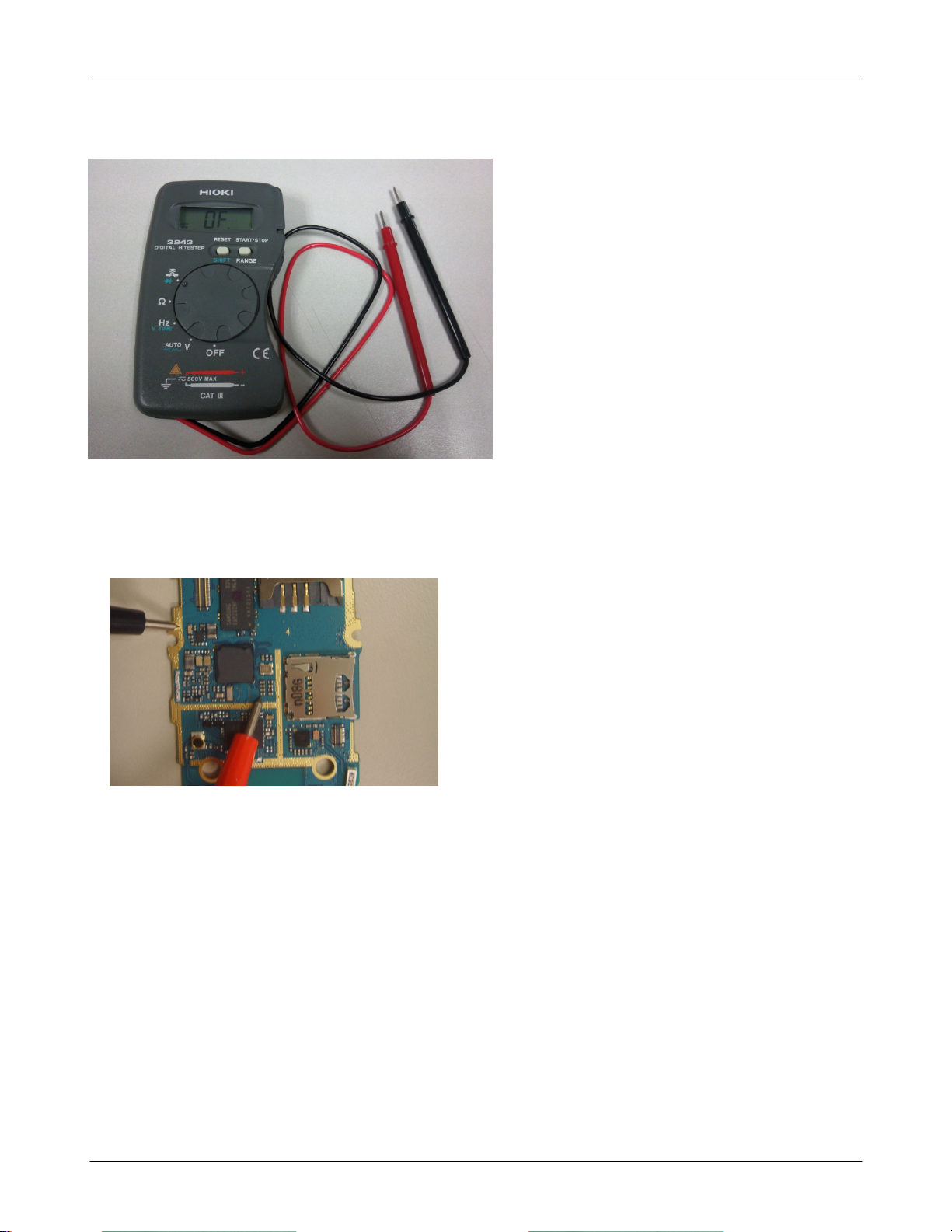
Multi-meter
Level3Repair
EX) to look up the TP, shunt Cap.
-
SAMSUNG Proprietary-Contents may change without notice
This Document can not be used without Samsung's authorization
Checking the TP(test point) using Multi-meter
if checking the GND, you can listen"beep"
-
if checking the Signal, you can't listen it.
8-5
Level3Repair
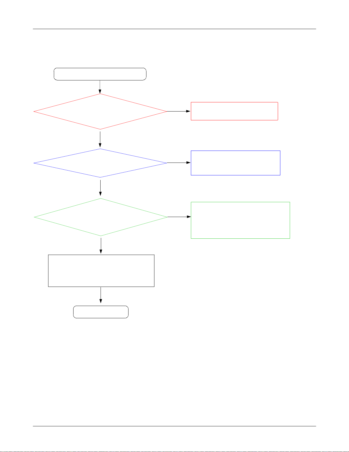
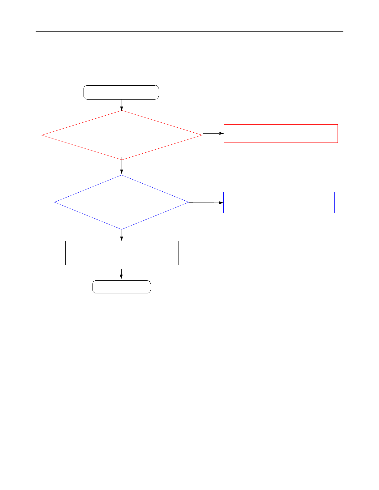
8-3-1.
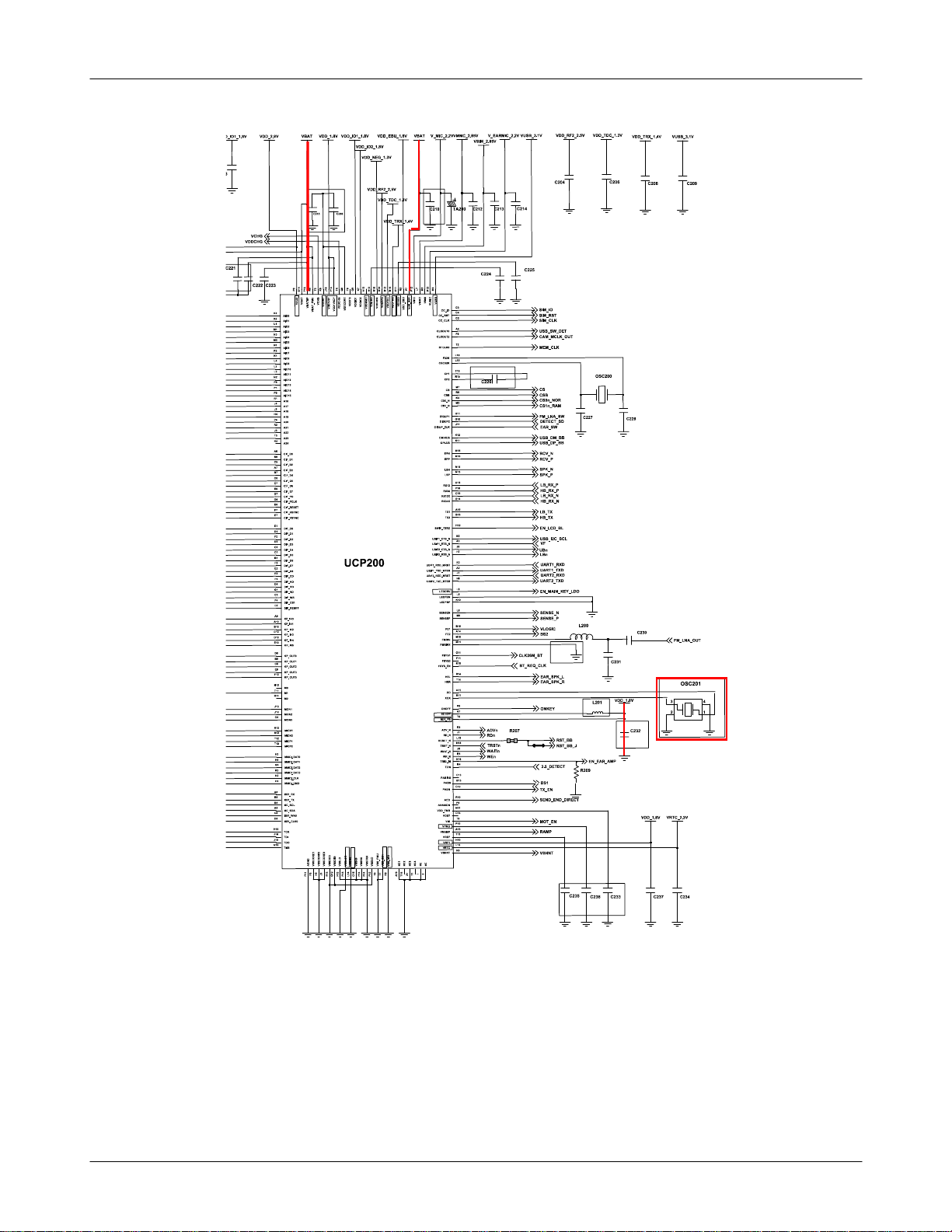
Power On
Power On'does not work
'
Check the Battery Voltage
is more than
TP:C
(
210 C220, C320)
VDD_1.8V
(
Check the Clock at
UCP200 A11pin
CLK26M)
(
TP:OSC201
(
Yes
Yes
=1.8
TP: C232)
Yes
=26M
3.7V
1,3
V?
HZ
pin
No
No
No
)
Change the Battery
Because of low batt. power)
(
Check the UCP200 is demaged.
Change the OSC201.
Yes
Check the UCP200 is demaged.
Yes
END
8-6
SAMSUNG Proprietary-Contents may change without notice
This Document can not be used without Samsung's authorization
Level3Repair
8-7
SAMSUNG Proprietary-Contents may change without notice
This Document can not be used without Samsung's authorization
Level3Repair
8-8
SAMSUNG Proprietary-Contents may change without notice
This Document can not be used without Samsung's authorization
Level3Repair
8-3-2.
Initial
Initial Failure
Yes
Check R207(RST_BB
using the oscilloscope
Yes
CheckUCP200pin D2
1.7V ?
TP: HEA4009pin
(
) > 1.7V?
.
>
)
No
No
Resolder the R208.
It must be higher than
Change the UCP200.
1.7
V.
Yes
Check the16bit data signalsare correct.
Yes
END
8-9
SAMSUNG Proprietary-Contents may change without notice
This Document can not be used without Samsung's authorization
Level3Repair
FM_LNA_OUT
OSC201
2431
R205
MMCI_DAT2 T2IN
VDD_1.8V
VDD_2.9V
HEA400
22
11
4
33
4
FLM_OUT
LED+_12V
LED-
LCD_RST LCD_WR_OUT
LCD_D(0)
LCD_D(1)
LCD_D(2)
LCD_D(3)
LCD_D(4)
LCD_D(5)
LCD_D(6)
5566
7788
99
11111212
1313 14 14
15151616
1717 18 18
1919
2121
23232424
2525 2626
27272828
29
29
C
C
C
N
N
N
2
1
3
3
3
3
C431
C428
LCD_RS_OUT
LCD_CS_OUT
LCD_RD
1010
20
20
2222
LCD_D(7)
3030
C
N
4
3
2.2" QVGA LCD
8-10
SAMSUNG Proprietary-Contents may change without notice
This Document can not be used without Samsung's authorization
Level3Repair
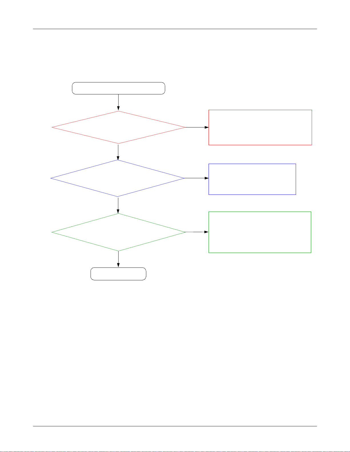
8-3-3.
Charging Part
Check the R301
Abnormal charging part
Yes
Check the Battery&TA
connection.
Yes
>4.9V?
Yes
No
No
Reinsert the Battery or TA.
Resolder the R301
Check the Q303 pin
>4.9V ?
Yes
END
3
No
Replace the Q303 usingaHeatgun
8-11
SAMSUNG Proprietary-Contents may change without notice
This Document can not be used without Samsung's authorization
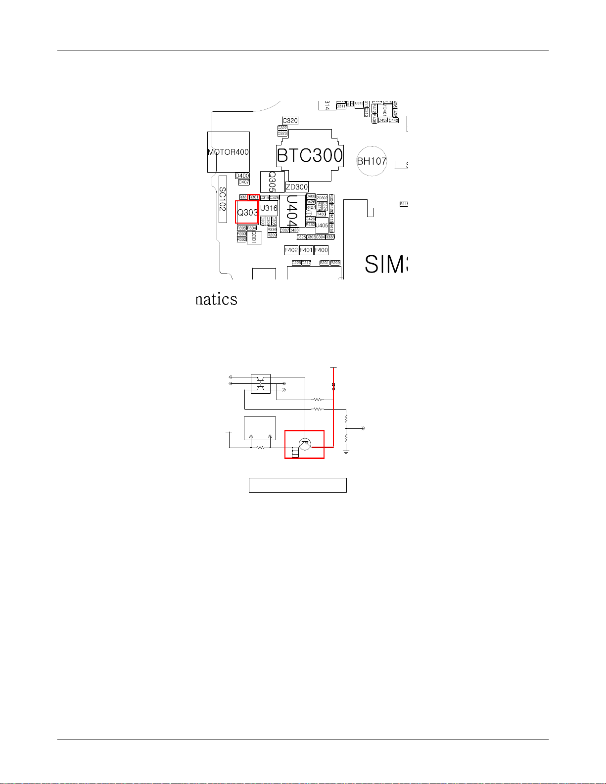
Level3Repair
CS
VBAT
Q301
1
6
2
5
34
Routed as a Pair FROM R315(0.1T)
N
_
E
S
N
E
S
R331
TNHSVBSC
VDDCHG
R302
R303
P
_
E
S
N
E
S
3
4
Q303
CHARGING CIRCUIT
VBUS_5V_OUT
R301
R305
VCHG
R334
8-12
SAMSUNG Proprietary-Contents may change without notice
This Document can not be used without Samsung's authorization
Level3Repair
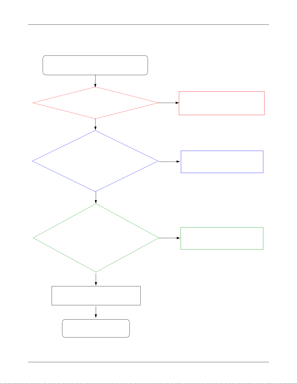
8-3-4.
Sim Part
Phone can't access SIM Card
Yes
Check the
SIM
Check the SIM_CLK signal is on.
method:wire the pin3(C303)
(
and check its waveform using an
pin1(C325)
300
After Power ON,
C303)
(TP:
oscilloscope)
Yes
】
2.85V
No
No
Resolder the UCP200 using heatgun.
Resolder or Replace SIM300 connector.
Because of not soldering well)
(
Yes
After SIM card insert,
Check the SIM
pin2(R333,C304: SIM_RST)
method:wirethe pin2and
(
check its waveform using an
Check the SIM Card is demaged.
2.85V?
oscilloscope)
END
300
】
Yes
Yes
No
Change the PBA.
8-13
SAMSUNG Proprietary-Contents may change without notice
This Document can not be used without Samsung's authorization
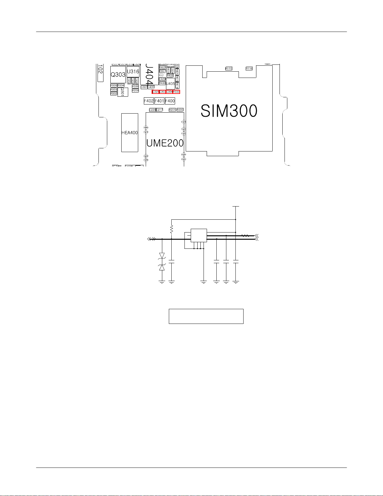
Level3Repair
VSIM_2.85V
SIM300
R332
6
6
11
5
5
4
7GG89GG10
22
33
C303 C304
SIM_IO SIM_CLK
ZD301
4
C302
C325
R333
SIM_RST
SIM SOCKET
8-14
SAMSUNG Proprietary-Contents may change without notice
This Document can not be used without Samsung's authorization
Level3Repair
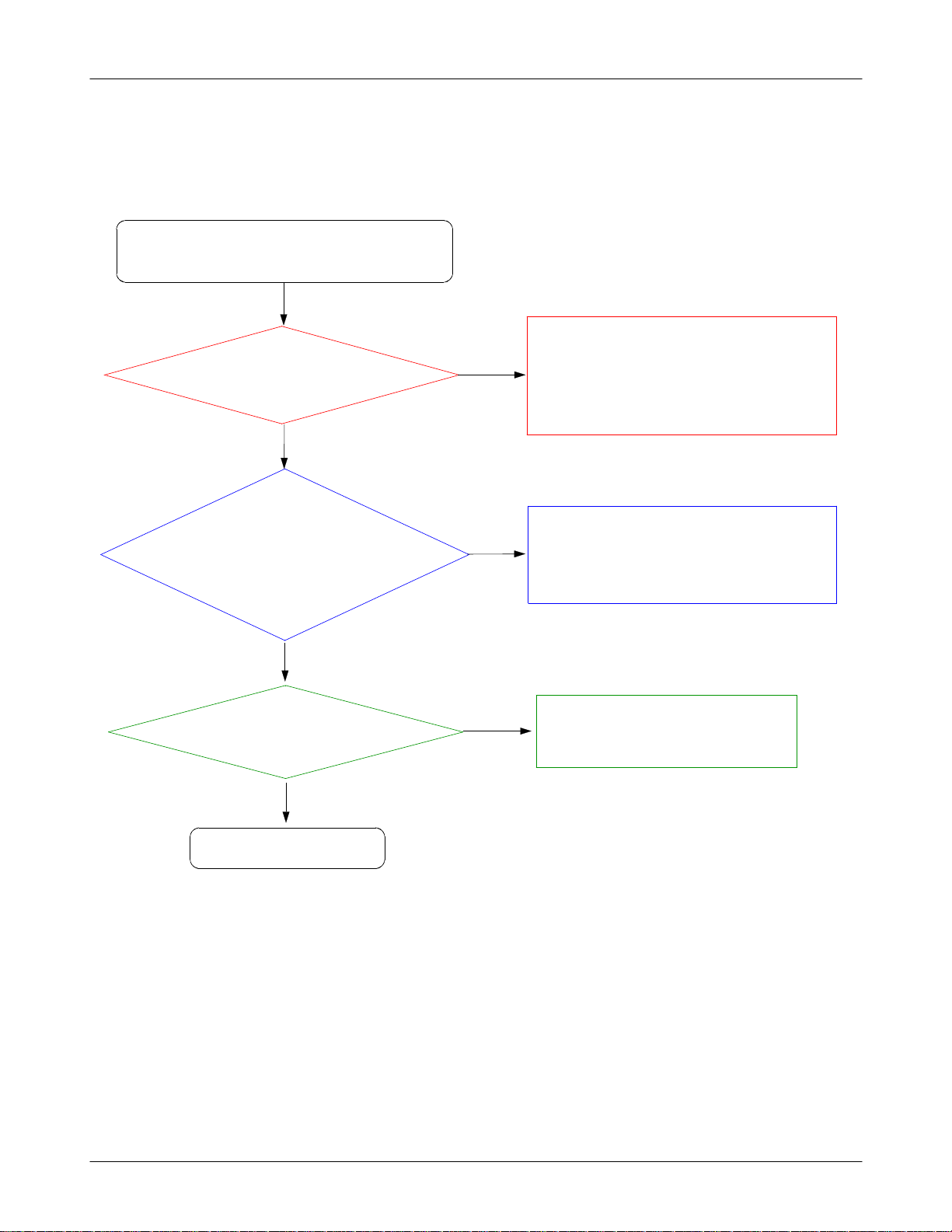
8-3-5.
Microphone Part
Microphone does not work
Check R432
at Mic Active?
Check the MIC signal paths.
MIC signals are on.
L403,L410,C422,
(TP:
C420,R432,R435,R437)
Yes
=2.2V
Yes
No
No
Replace the UCP200 usingaHeatgun
Because of not soldering well
(
Resolder L403, L410, C422, C420, R432, R435,
R437
not work if those is not connected.)
(
)
Yes
Check the MIC is demaged.
Yes
END
No
Replace an another MIC
8-15
SAMSUNG Proprietary-Contents may change without notice
This Document can not be used without Samsung's authorization
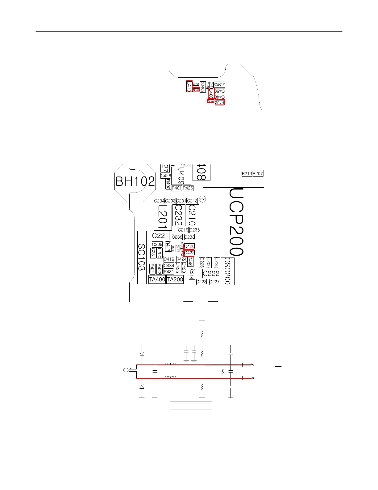
Level3Repair
A
XAUX
V_MIC_2.2V
R432
C424
C422
C447
R436
C420
C453
MIC_P
MIC_N
AU
P
MIC400
R435
C446
2
C441
0
4
D
Z
3
0
4
D
Z
L403
C448
L410
C451
C450
R437
MAIN MIC
8-16
SAMSUNG Proprietary-Contents may change without notice
This Document can not be used without Samsung's authorization
Level3Repair
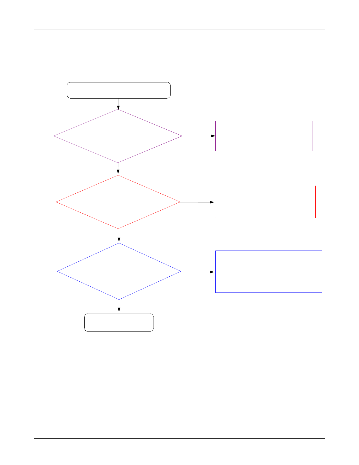
8-3-6.
Speaker Part
Check the UCP N15,N16 pin
Speaker does not work
Yes
signals are on.
L405, L406)
(TP:
Yes
Check the SPK signal
paths.
Are signal on?.
C412,C440)
(TP:
No
Replace the UCP200 using the Heatgun.
because of soldering not well)
(
No
Resolder the L405, L406.
Yes
Check the Speaker module
is Okay.
Yes
END
No
Replace the SPK module.
8-17
SAMSUNG Proprietary-Contents may change without notice
This Document can not be used without Samsung's authorization
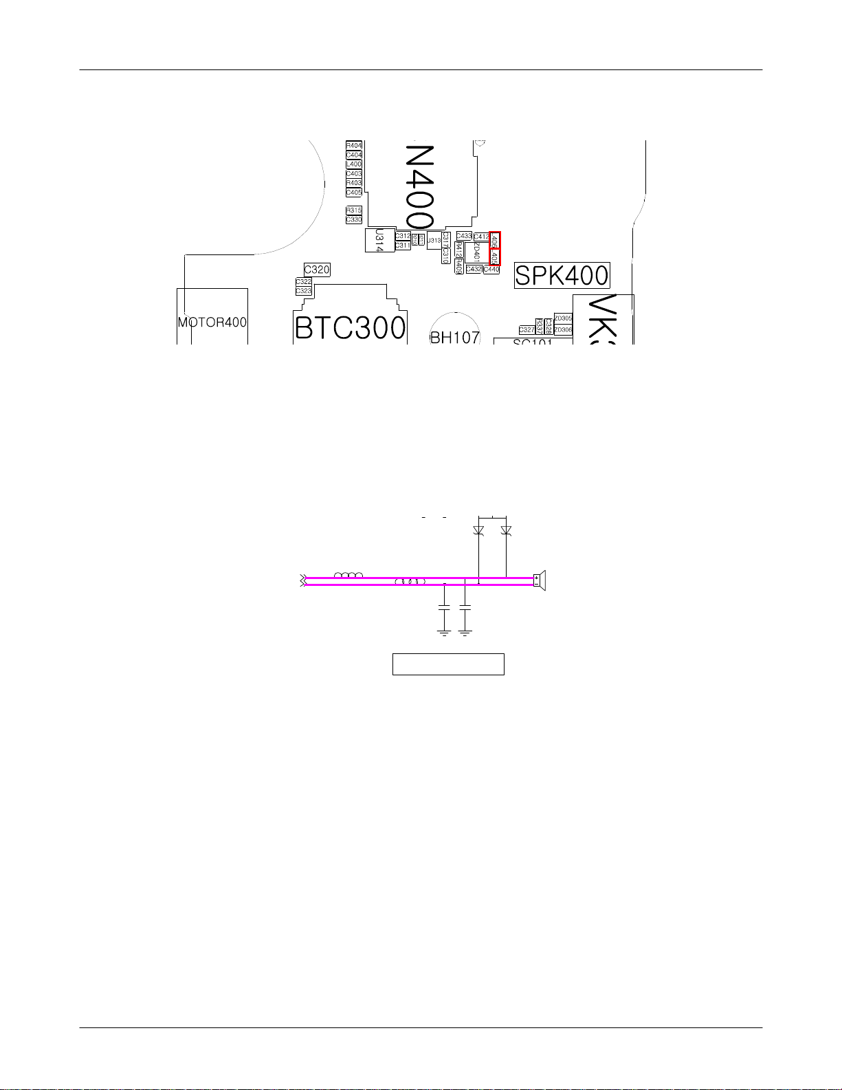
Level3Repair
ZD401
SPK_P
SPK_N
4
6
SPK400
L405
L406
C440C412
SPK / RCV
F400
8-18
SAMSUNG Proprietary-Contents may change without notice
This Document can not be used without Samsung's authorization

Level3Repair
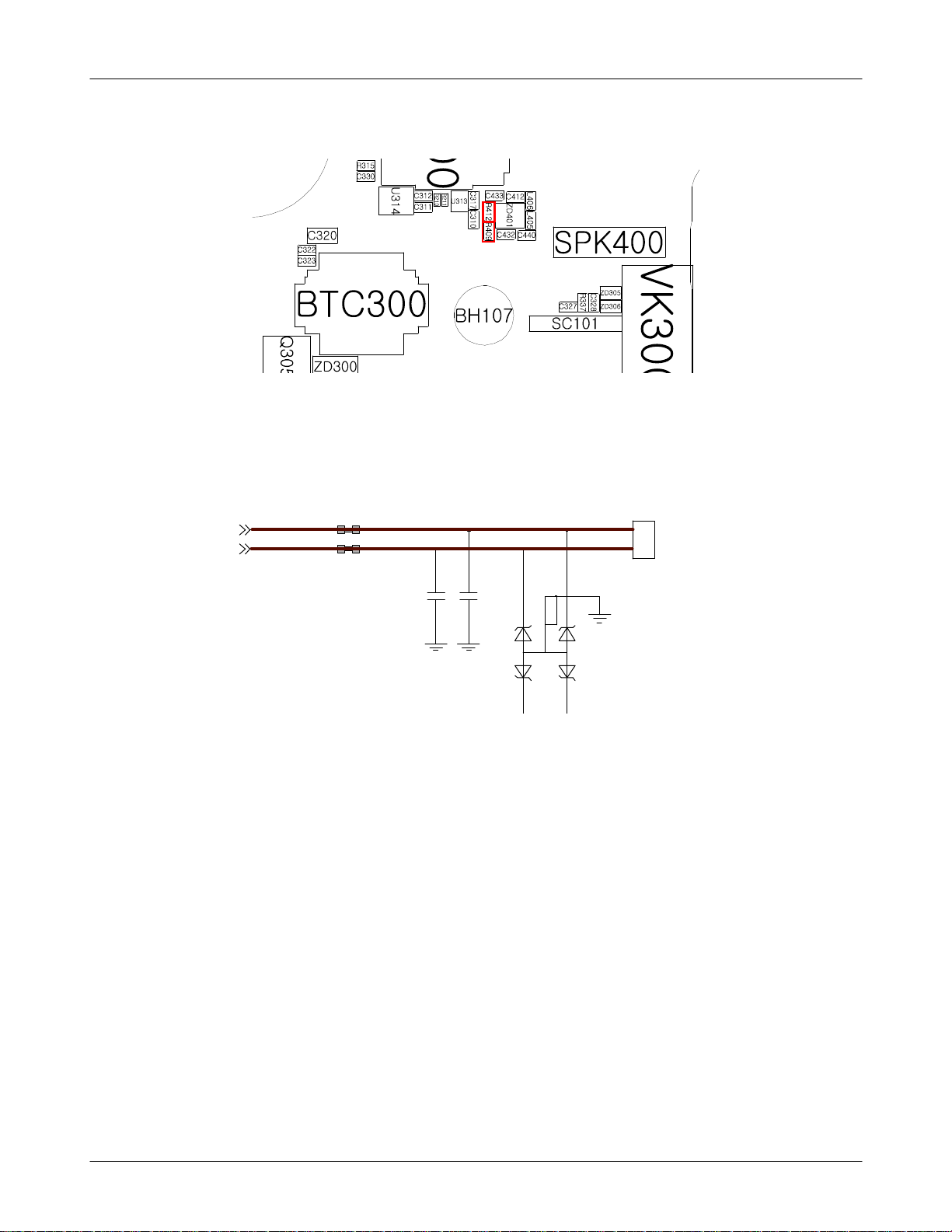
8-3-7.
RCV Part
Receiver does not work
Yes
Check the UCP M15,M16
pin signal is on.
R412, R409)
(TP:
Yes
Check the RCV signal
paths
Are signals on?.
C432,C433)
(TP:
No
Replace the UCP200 using the Heatgun.
because of soldering not well)
(
No
Resolder the R412, R409.
Yes
Check the RCV module is
Okay.
Yes
END
No
Replace the RCV module.
8-19
SAMSUNG Proprietary-Contents may change without notice
This Document can not be used without Samsung's authorization
Level3Repair
RCV_P
RCV_N
R412
R409
RCV400
1
1
2
2
C433C432
3
1
5
2
ZD401
4
6
MIC400
8-20
SAMSUNG Proprietary-Contents may change without notice
This Document can not be used without Samsung's authorization
Level3Repair
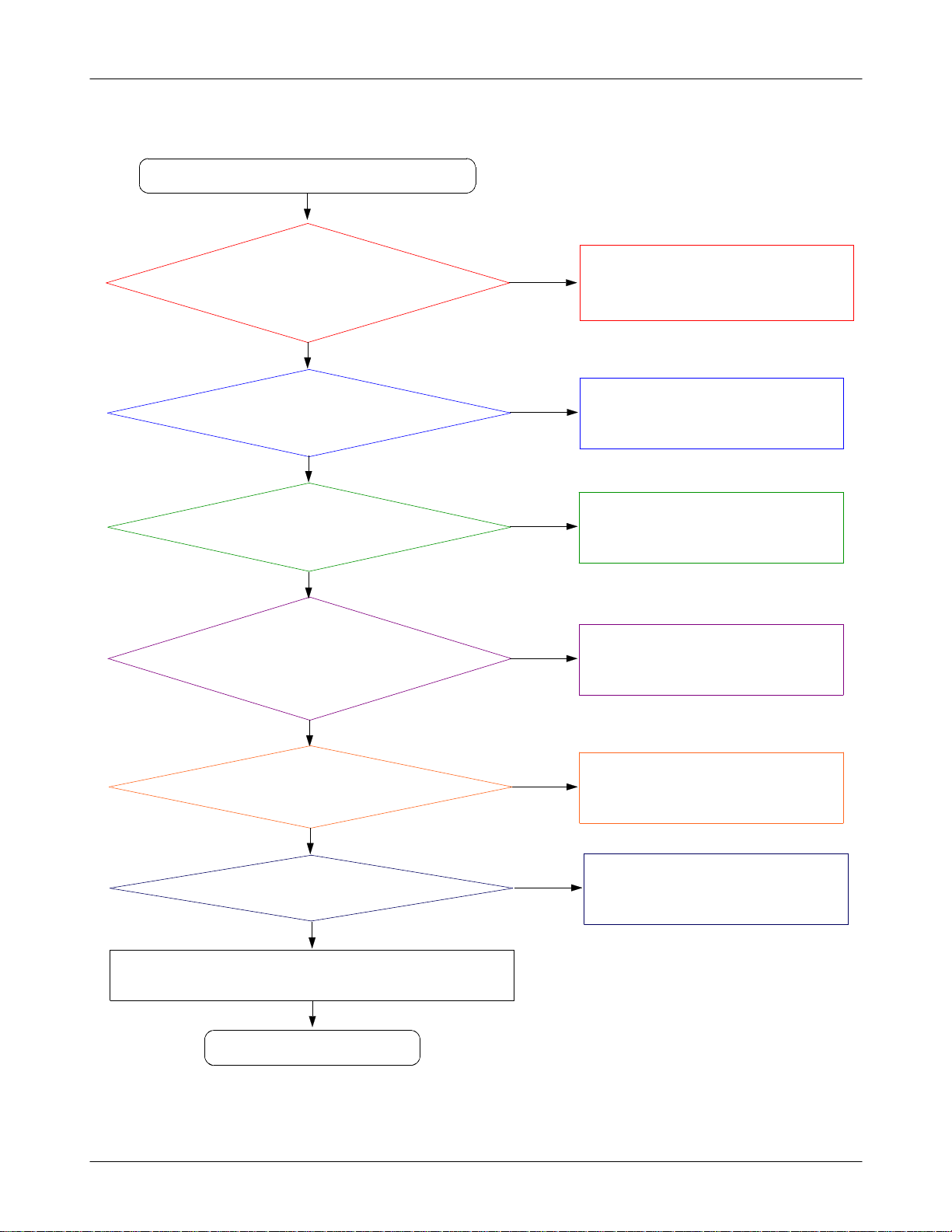
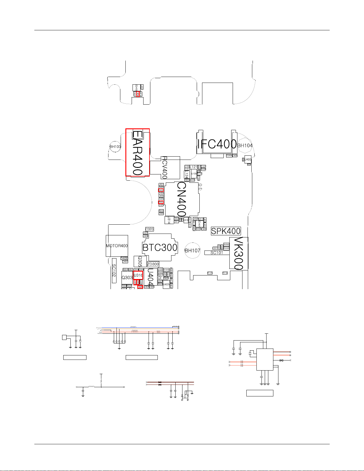
8-3-8.
EAR_Speaker Part
Ear_Speaker is not working.
Check the earphone connector is
demaged.
Check the L404
Check EarAmp enable signal is
(TP:
Check the Ear signals are on,
while playing the sound.
(TP:
Yes
=0V
Yes
correct.
R336
=1.8
Yes
C308, C309)
Yes
V)
No
No
No
Resolder the L404 or Replace the EAR
connector(EAR400)
Resolder the R336 or Replace the UCP200.
Resolder the C308, C309 or Replace the
UCP200.
Check the Ear signals passing
the Ear AMP are on, while
playing the sound.
R404, R403)
(TP:
Yes
Check the ear signal paths
Are signals on?.
L401,L400)
(TP:
Yes
Check EAR400 pin
demaged.
Yes
Change the EAR400.
Yes
END
6, 7
is
No
No
No
Resolder the Ear AMP(U316).
Resolder the R404, R403, L401, L400.
Change the Ear phone.
8-21
SAMSUNG Proprietary-Contents may change without notice
This Document can not be used without Samsung's authorization
Level3Repair
MOTOR400
2
2
1
1
MOTOR
V_MOT_3.3V
C407
EAR400
CON-A
2
CON-B
3
CON-F
7
CON-E
6
CON-D
5
CON-C
4
D400
L402
L401
L400
1
6
5
4
3
ZD400
2
R404
R403
C403C402
3.5PI EAR JACK
VDD_1.8V
R414
L404
C452
3.5_DETECT3.5_CON_DETECT
R412
RCV_P
RCV_N
R409
SEND_END
EAR_MIC_P
FM_ANT_EAR
EAR_3.5_L
EAR_3.5_R
3.5_CON_DETECT
C405
C404
C433C432
3
5
1
2
ZD401
EAR_SPK_L
EAR_SPK_R
C306 C307
C308
C309
VDD_1.8V
3
4
C326
C
C
D
D
V
A3
P
C1N
A4
C1P
C1
INL
C2
INR NC
S
D
S
N
V
G
P
3
2
B
A
C319
EAR_AMP
N
I
V
P
OUTR
_SHDN
4
B
U316
B1
OUTL
A1
B2
1
D
2
NC
N
G
P
EAR_3.5_L
EAR_3.5_R
EN_EAR_AMP
R336
8-22
SAMSUNG Proprietary-Contents may change without notice
This Document can not be used without Samsung's authorization
Level3Repair
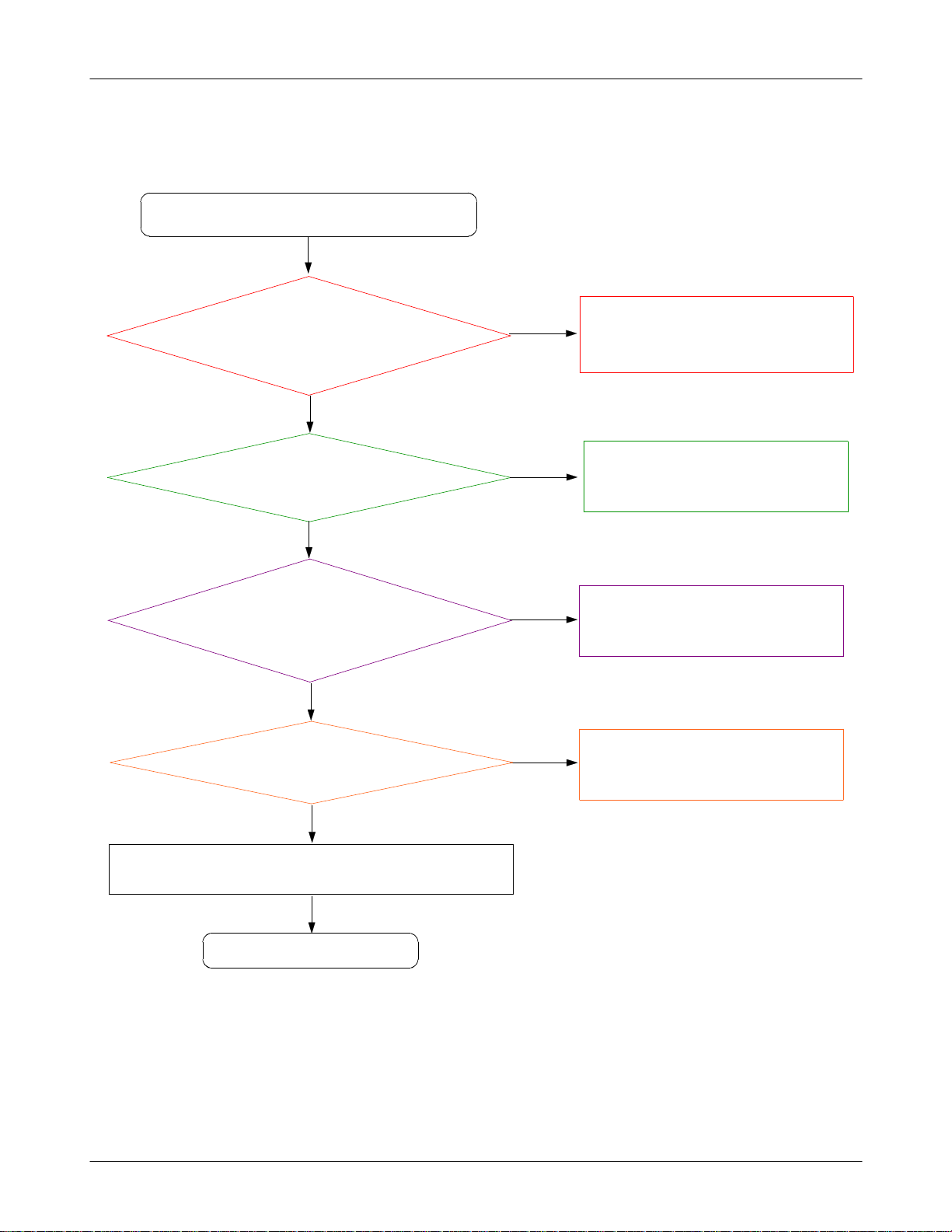
8-3-9.
EAR_MIC Part
Ear_Microphone is not working.
Check the EAR connector is
(TP:
Check the Ear_Mic voltage is on.
Yes
demaged.
L402 signal is on.)
Yes
R421
(TP:
=2.2
Yes
V)
No
No
Resolder the L402 or Replace the EAR
connector(EAR400)
Resolder the R421 or Replace the UCP200.
Check the signal paths
Are signals on?.
C434, C423, R431, R422)
(TP:
Yes
Check the UCP200 is demaged.
Yes
Resolder the UCP200 using the heatgun.
Yes
END
No
Resolder the C434, C423, R431, R422
No
Check the EAR phone.
8-23
SAMSUNG Proprietary-Contents may change without notice
This Document can not be used without Samsung's authorization
 Loading...