

Page 1
SyncMaster 170T/180T 5-1
5 Troubleshooting
Notes: 1. Before troubleshooting, setup the PC’s display as below.
• Resolution: 1280 x 1024
• H-frequency: 64 kHz
• V-frequency: 60 Hz
2. If no picture appears, make sure the power cord is correctly connected.
3. Check the following circuits.
• No raster appears: Stand PCB, Main PCB
• 14V develop but no screen: Main PCB
• 14V does not develop: Main PCB
4. If you push and hold the EXIT button for more than 5 seconds, the monitor automatically turns back
to the factory preset.
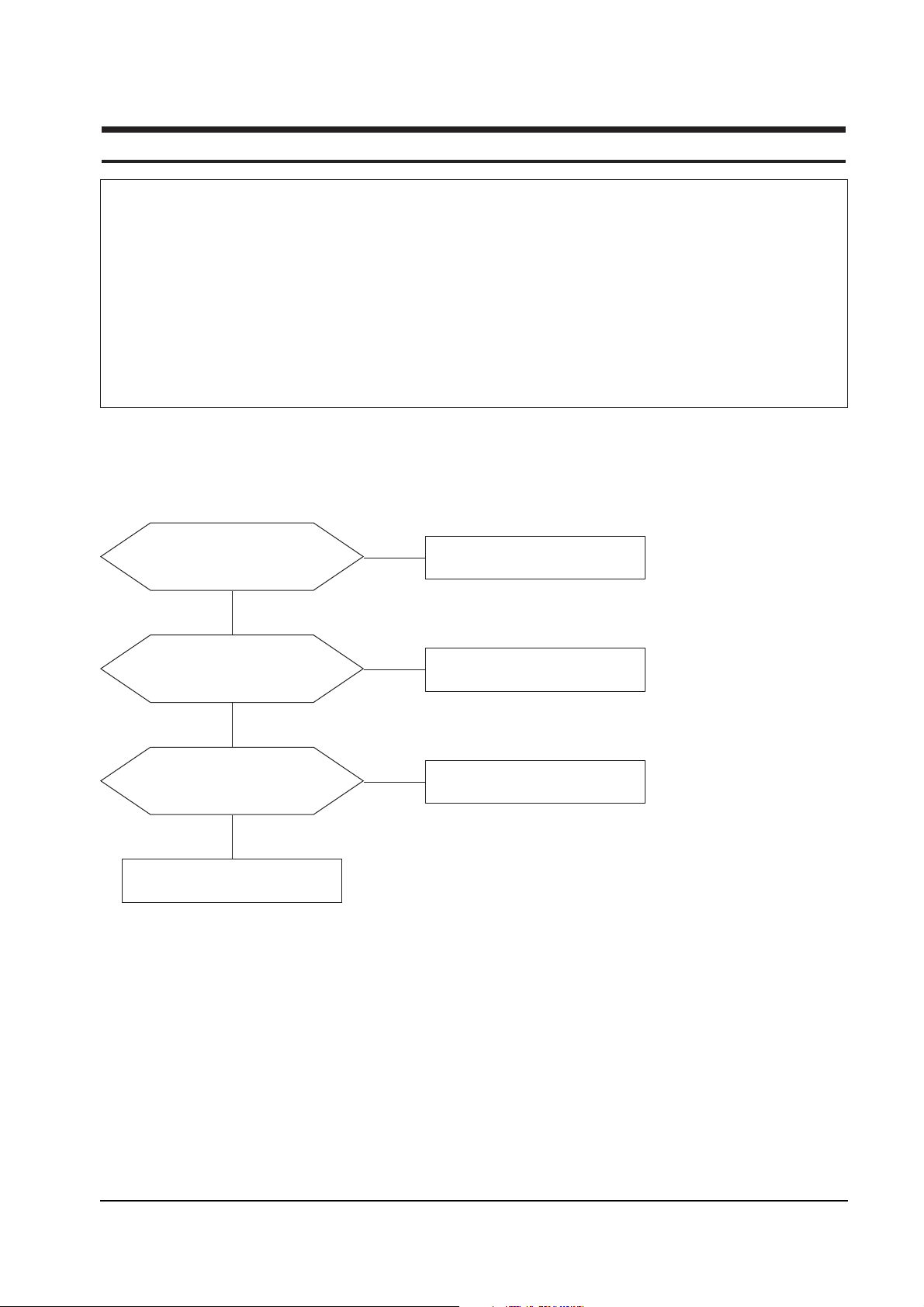
5-1 No Power
Does proper DC 14 V appear at
DC jack connected to CN101?
Check Power Adaptor.
Yes
No
Does proper DC 5 V appear at
Pin 4 of IC105?
Check IC105 and related circuit.
Check Q102, Q103 and Q105.
Yes
No
Does proper 5 V - signal appear at
Pin 42 of IC602 (SW_REG_EN)?
Check IC602 and related circuit.
(CN102, Function Key)
Yes
No
Page 2
5 Troubleshooting
5-2 SyncMaster 170T/180T
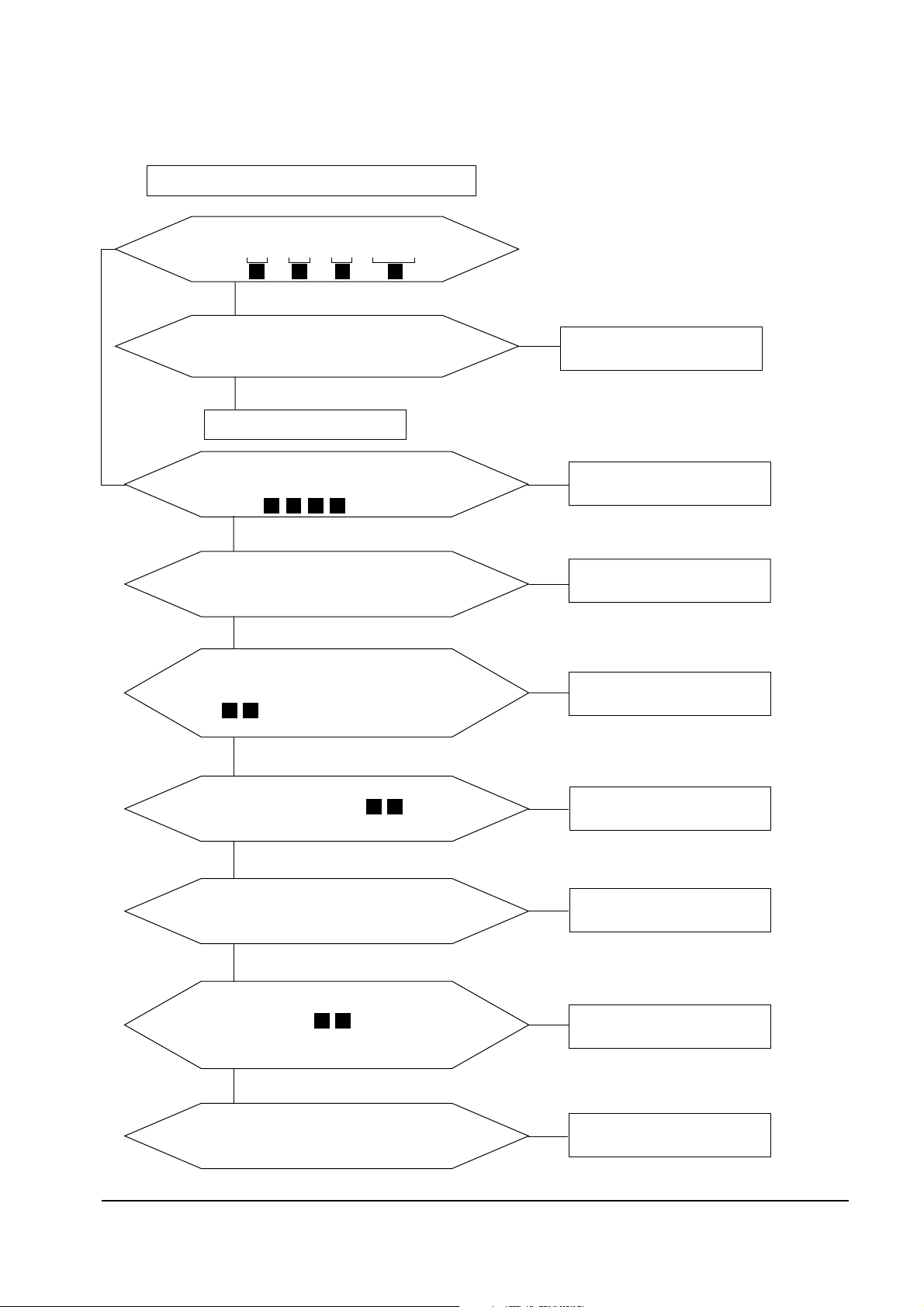
5-2 No Video [Analog]
Check signal cable and connection.
Check PC Signal
No
No
No
Does the analog video signal appear at
R200,R201, R202? (BLUE, GREEN, RED)
Yes
Check IC244 and related circuit.
Does the sync signal appear
at the output of Pin 18, 14 of IC 244 ?
(V_SYNC, H*V_SYNC)
Yes
No
Check the related circuit
for these ports
No
Check IC501 and related circuit.
No
Check IC501 and related circuit.
No
Check IC300 and related circuit.
No
Does the input signal appear at the Pin 40, 41 of
IC 300?
(PLL H*V, MX-PDEN)
Yes
During power on-off, does the input signal
appear at the Pin29,30 of IC300?
(AD-SDA, AD-SCL)
Do the clock and sync signal appear at Pin115,
117 of IC 300? (A_DCLKAB,
A_MX_HSYNC) and does the digital video signal
appear at the output port PDA, PDB)?
Yes
During power on-off dose the input signal
appear at the R 410 and R 411 ?
(MX-SDA, MX-SCL)
Yes
7 8
9 10
1 2 3 4
5 6
Does the digital video signal appear
at the Pin 34, 35, 39, 40, 42, 43, 45 and 46 of IC601?
Yes
Is the output of Pin 1, 19 of IC602 High?
Check TFT-LCD panel and Inverter.
Yes
replace IC601
Yes
15 16 17 18
Check IC602 and related circuit.
No
Does the input signal appear at Pin of 76, 77, 78,
80 of IC601 (LDTGB, LVSYNCB, LHSYNCB, LCKBB)
Page 3

5 Troubleshooting
SyncMaster 170T/180T 5-3
5-2-1 No Video [Digital]
Check signal cable and connection.
Check PC Signal and IC101
Does the input signal appear at Pin of 76, 77, 78,
80 of IC601 (LHSYNCB, LVSYNCB,LDTGB, LCKBB)
No
No
No
Does the digital signals appear at R328, R329,
R330,R332, R333, R334, R335 and R336 (IC101)?
Yes
Check IC244 and related circuit.
Does the sync signal appear
at the output of Pin 18, 14 of IC 244 ?
(V_SYNC, H*V_SYNC)
Yes
No
Check the related circuit
for these ports
No
Check IC501 and related circuit.
No
Check IC101 and related circuit.
No
Does the input signal appear at the Pins 40, 41
of IC 300?
( PLL H*V, MX_PDEN)
Do the clock and DE signal appear at Pin 44, 46 of
IC 101? (T_,DCLK, T_DE) and does the
digital video signal appear at the output port PDA,
PDB)?
Yes
During power on-off dose the input signal
appear at the R 410 and R 411 ?
(MX-SDA, MX-SCL)
Yes
7 8
19 20
1 2 3 4
5 6
Does the digital video signal appear
at the Pin 34, 35, 39, 40, 42, 43, 45 and 46 of IC601?
Yes
Is the output of Pin 1, 19 of IC602 High?
Check TFT-LCD panel and Inverter.
Yes
Replace IC601
Yes
15 16 17 18
Check IC602 and related circuit.
No
18
151617
Page 4

5-4
5 Troubleshooting
SyncMaster 170T/180T
WAVEFORMS
2
CH1 RMS = 3.25V
3
CH1 RMS = 3.12V
4
CH1 RMS = 2.20V
5
CH1 RMS = 3.3V
6
CH1 RMS = 3.3V
17
CH1 RMS = 3.08V
18
CH1 RMS = 3.08V
9
CH1 RMS = 2.50V
10
CH1 RMS = 960mV
15
CH1 RMS = 3.3V
16
CH1 RMS = 3.3V
8
CH1 RMS = 3.24V
1
CH1 RMS = 3.26V
7
CH1 RMS = 3.20V
19
CH1 RMS = 2.78V
20
CH1 RMS = 3.22V
Page 5

5-5
5 Troubleshooting
SyncMaster 170T/180T
Replace IC404.
Yes
No
There is video but no OSD.
5-3 No OSD
While pushing a front control
button does any pulse appear
at Pin 12 of IC404?
WAVEFORMS
Does input signal appear
at the Pins 2, 5 and
10 of IC404?
Check IC405 and related circuit.
Check IC404 and related circuit.
Yes
No
11 12 13
11
CH1 RMS = 4.18V
13
CH1 RMS = 3.26V
12
CH1 RMS = 3.26V
 Loading...