

Page 1
SyncMaster 170T/180T 4-1
4 Alignments and Adjustments
This section of the service manual explains how to use the DDC JIG to adjust the black, red, green, and blue
levels of the FPD when you replace the AD Board, and how to update the microprocessor when you
change the Panel or Lamp(s).
4-1 Required Equipment
The following equipment is necessary for adjusting the monitor:
• Oscilloscope with probe tool
• Computer with Windows 95 , Windows 98 , or Windows NT .
• DV17AS.exe software
• DDC Control JIG
4-2 Using the DDC Control JIG
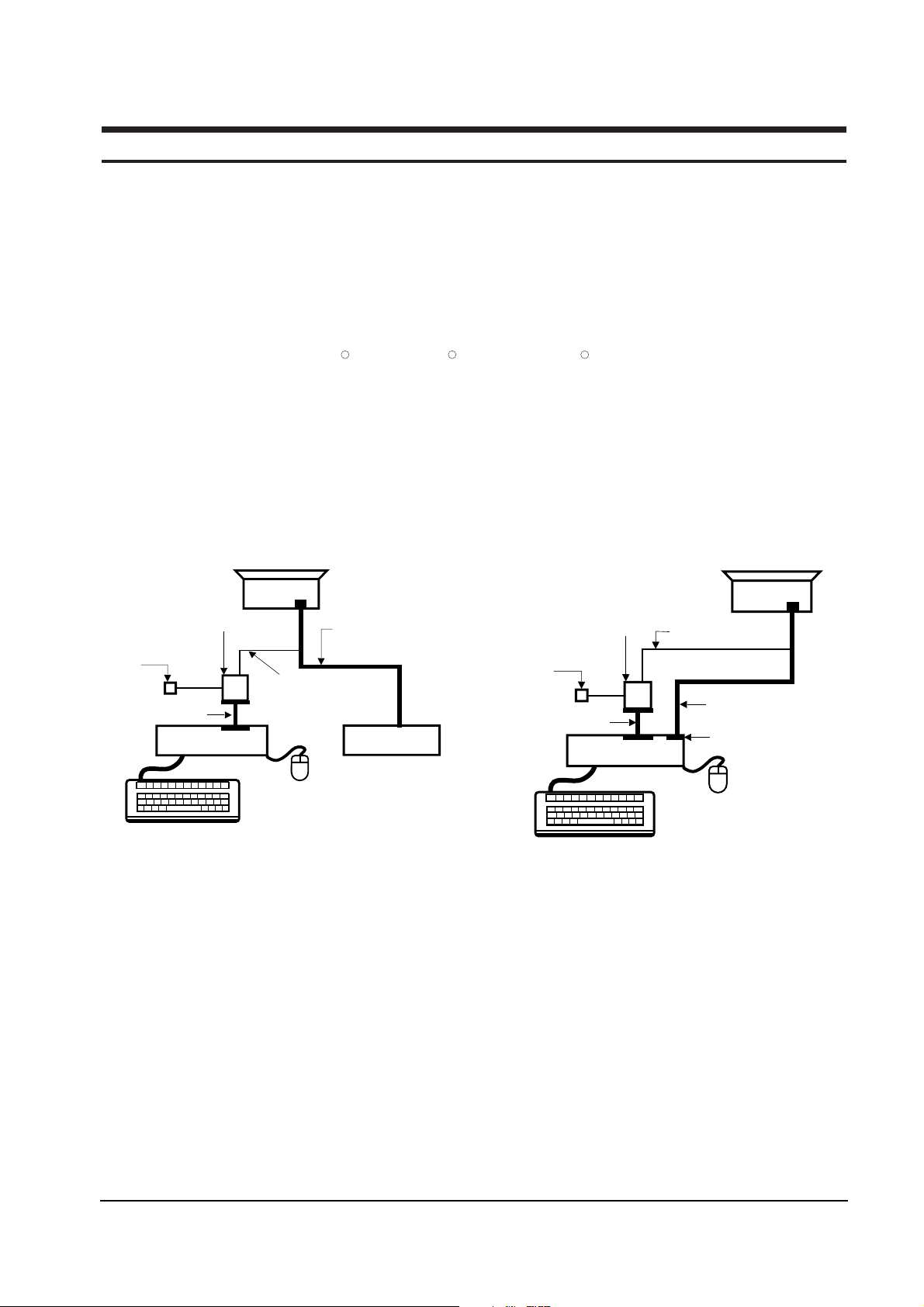
After replacing the LCD Panel, Lamp(s), and / or AD Board, use the DDC Control JIG to complete your
service. Attach the DDC Control JIG to the flat panel display (FPD) as shown in the diagrams, below.
MONITOR
INTERFACE
BOARD VER. 2.0
PC
SIGNAL
GENERATOR
3-WIRE
CABLE
SIGNAL CABLE
5V DC
ADAPTOR
PARALLEL CABLE
Figure 4-1. Setup 1, With Signal Generator
MONITOR
INTERFACE
BOARD VER. 2.0
PC
3-WIRE CABLE
SIGNAL CABLE
PARALLEL CABLE
D-SUB
CONNECTOR
5V DC
ADAPTOR
Figure 4-2. Setup 2, Without Signal Generator
R R R
Page 2
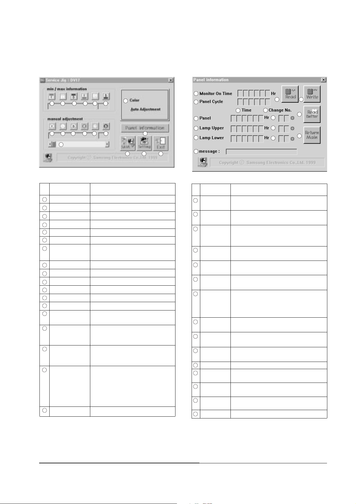
4-2-1 Main Menu
4-2-1 (a) Service JIG : DV17
4-2-2 Sub Menu
4-2-2 (a) Panel Information
No Label Definition
No Label Definition
4 Alignments and Adjustments
4-2 SyncMaster 170T/180T
Monitor On Time
Total hours that the monitor has been actively
functioning.
Panel Cycle The total number of times the Panel has been
turned ON.
Time Total in Hours that this Panel or Lamp has been
ON. Reset this number to 000000 after
replacing the part.
Panel Total number of hours that this Panel has
been ON.
Lamp, Upper Total number of hours that this Upper Lamp
has been ON.
Lamp, Lower Total number of hours that this Lower Lamp
has been ON.
Change No. The number of times this Panel or Lamp has
been replaced. The numbers are 00 if the item
is the original factory part installed during
manufacture of this monitor.
Panel Replacement times. This value is 00 if original
equipment.
Lamp, Upper Replacement times. This value is 00 if original
equipment.
Lamp, Lower Replacement times. This value is 00 if original
equipment.
Message Shows the message.
Read Reads all Panel information data from the
AD Board
Write Writes the Panel Parameter Control values to the
AD Board
Read buffer Reload the Panel Parameter Control values from
the Program buffer
Return Main Returns to the Main menu
Figure 4-4. Control JIG Menu
Red max value Shows the red video signal max value
Green max value Shows the green video signal max value
Blue max value Shows the blue video signal max value
Red min value Shows the red video signal min value
Green min value Shows the green video signal min value
Blue min value Shows the blue video signal min value
Color Automatical screen contrast setting
Auto Adjustment
Red gain control Adjusts the red video signal gain control
Green gain control Adjusts the green video signal gain control
Blue gain control Adjusts the blue video signal gain control
Red cutoff control Adjusts the red video signal cutoff control
Green cutoff control Adjusts the green video signal cutoff control
Blue cutoff control Adjusts the blue video signal cutoff control
Panel information Shows the sub menu to panel information
(4-2-2 (a))
Scroll bar Changes the value or level of the selected
item. The window to the right shows the
value as it changes.
SAVE Saves the current adjustment value of
the R,G,B video contrast gain and
cutoff level
Setting Displays and allows you to adjust the
PC and Control JIG communication
environment. Use this button to change the
Delay parameter and Port Address of
your PC system and to test the connection
between the Control JIG and your computer
Exit Quits the DDC Control JIG
Figure 4-3.Service JIG Menu
1 2 3 4 5 6
7
8 9
10 11 12 13 14
15
16 17 18
a
b
d
e
f
k
c
g
h
i
j
n
o
l
m
1
2
3
4
5
6
7
8
9
10
11
12
13
14
15
16
17
18
a
b
c
d
e
f
g
h
i
j
k
l
m
n
o
Page 3

4-2-3 Adjustment Procedures
Use the following procedures whenever you
replace the AD Board, Panel, or one or both of the
Lamps.
4-2-3 (a) When Replacing the AD Board
1. Before replacing the AD Board, read all Panel
information data by using the Read button on
the DDC Control JIG.
2. Remove the old AD Board and replace it with
a new board.
3. Perform the procedures described in section
4-2-3 (b).
4. Write the Panel information data to the new
AD Board by using the Write button.
5. Perform other procedures using the DDC
Control JIG, if necessary.
6. When all procedures are complete, select the
Exit button ( ) to quit the DDC Control JIG
software.
4-2-3 (b) Color Auto Adjustment
1. After displaying 16-Gray pattern or black and
white mixed pattern, click “Color Auto
Adjustment” button.
2. During normal execution of Auto Algorithm
the screen image may flicker. If Auto
Algorithm does not excute properly, check
DDC Control JIG.
3. After normal execution of Auto Algorithm,
confirm optimal settings by observing the
contrast of several different patterns on the
display.
4. If you want to check each color value, click the
button from to and from to
4-2-3 (c) When Replacing the Panel
1. Select the Read Buffer button ( ) to gather the
current information about this monitor.
2. Increment the number by clicking on the (+)
button on the Panel row in the Change No.
column. If they were not already 00, the
numbers for the Upper and Lower Lamps will
automatically change to 00.
3. Check all values. If there is an error, select
Read Buffer again and increment the Change
No. column to the correct number. When all
values are correct, select the Write button ( )
to record the data in the firmware.
4. Select the Return Menu button ( ) to Return
Main Menu.
4-2-3 (d) When Replacing the Upper and/or Lower Lamp
1. Select the Read Buffer button ( ) to gather
current information about this monitor.
2. Increment the number by clicking on the (+)
button on the Lamp Upper and/or Lamp
Lower row in the Change No. column.
3. Check all values. If there is an error, select
Read Buffer again and increment the Change
No. column to the correct number(s). When all
values are correct, select the Write button
( ) to record the data in the firmware.
4. Select the Return Menu button ( ) to Return
Main Menu.
4 Alignments and Adjustments
SyncMaster 170T/180T 4-3
1
6 8 13
18
n
o
m
n
m
o
Page 4

Memo
4 Alignments and Adjustments
4-4 SyncMaster 170T/180T
 Loading...