


SCOPE2.0 Plus
User Manual
(GIS-PAMSC3)
V0.1

SCOPE2.0 Plus User Manual
[ Revision History ]
Version
V0.1 2016.11.13 Draft
V0.2 2017.02.02 Add SCOPE2.0Plus
Date Change History author
Sangho
Lee
Sangho
Lee
Confirmed
by
inho.won
inho.won
1

SCOPE2.0 Plus User Manual
1. Introduction
SCOPE2.0 Plus is a device for transferring vibration signal and equipment
information to an agent PC through wired/wireless communication. Users are
advised to read carefully all manuals provided with the package, to ensure safe
and efficient use of SCOPE2.0 Plus unit. This manual explains necessary skills
and information for setting up and using SCOPE2.0 Plus
2
SCOPE2.0 Plus User Manual
2. SCOPE2.0 Plus Specification
SCOPE2.0 Plus Platform comprise two boards(Main Board, Interface Board)
and Sensor Module comprise one board. Each Board Contains following
components
1) Board Components
A. Platform
i. Main Board : CPU / RAM / Flash / Power Module
ii. Interface Board : WIFI / LAN
B. Sensor Module
i. Analog Vibration sensor interface Filter
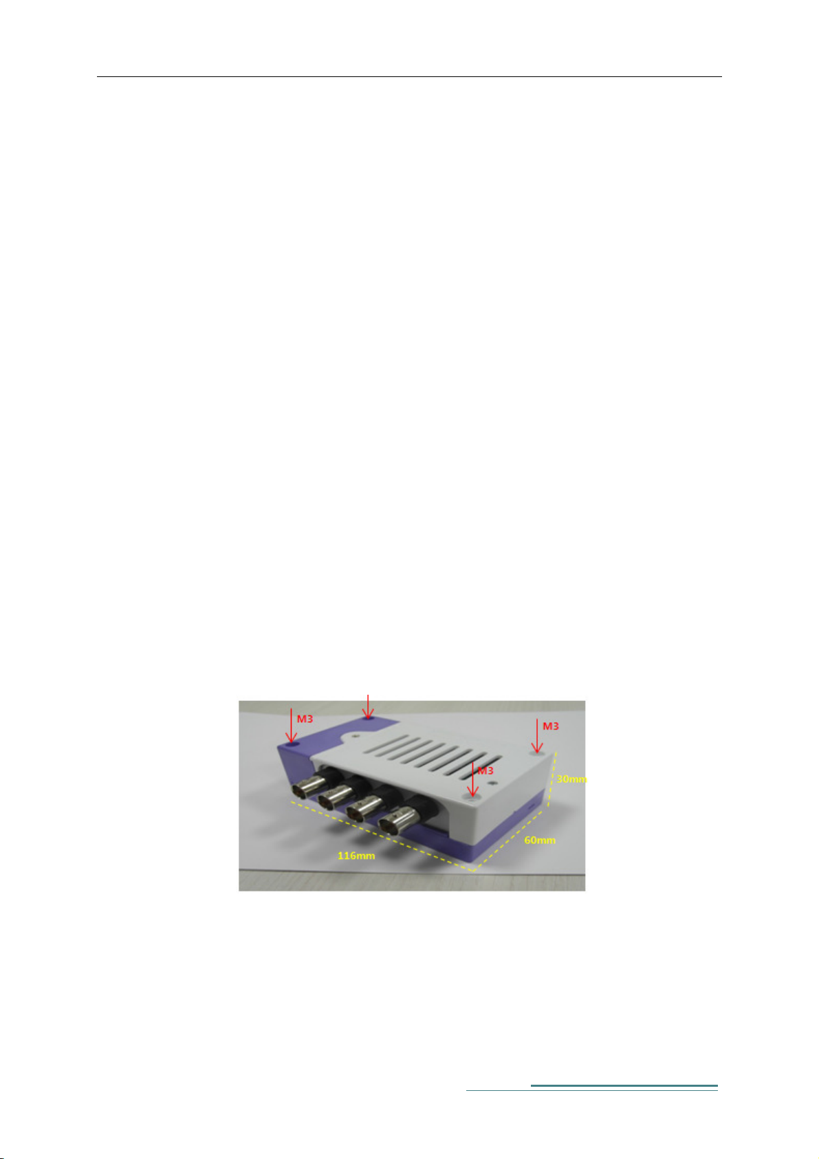
2) Exterior
This picture is of SCOPE2.0Plus Board and case. The front panel of
SCOPE2.0 Plus has Power (24Vdc), USB OTG, LAN Port, RS-232 4Port, a
Port of external antenna, LED. The rear panel of SCOPE2.0 Plus has FG.
The Sid panel of SCOPE2.0 Plus has Sensor Connector (BNC)
Figure 1 SCOPE2.0 Plus Exterior
3
SCOPE2.0 Plus User Manual
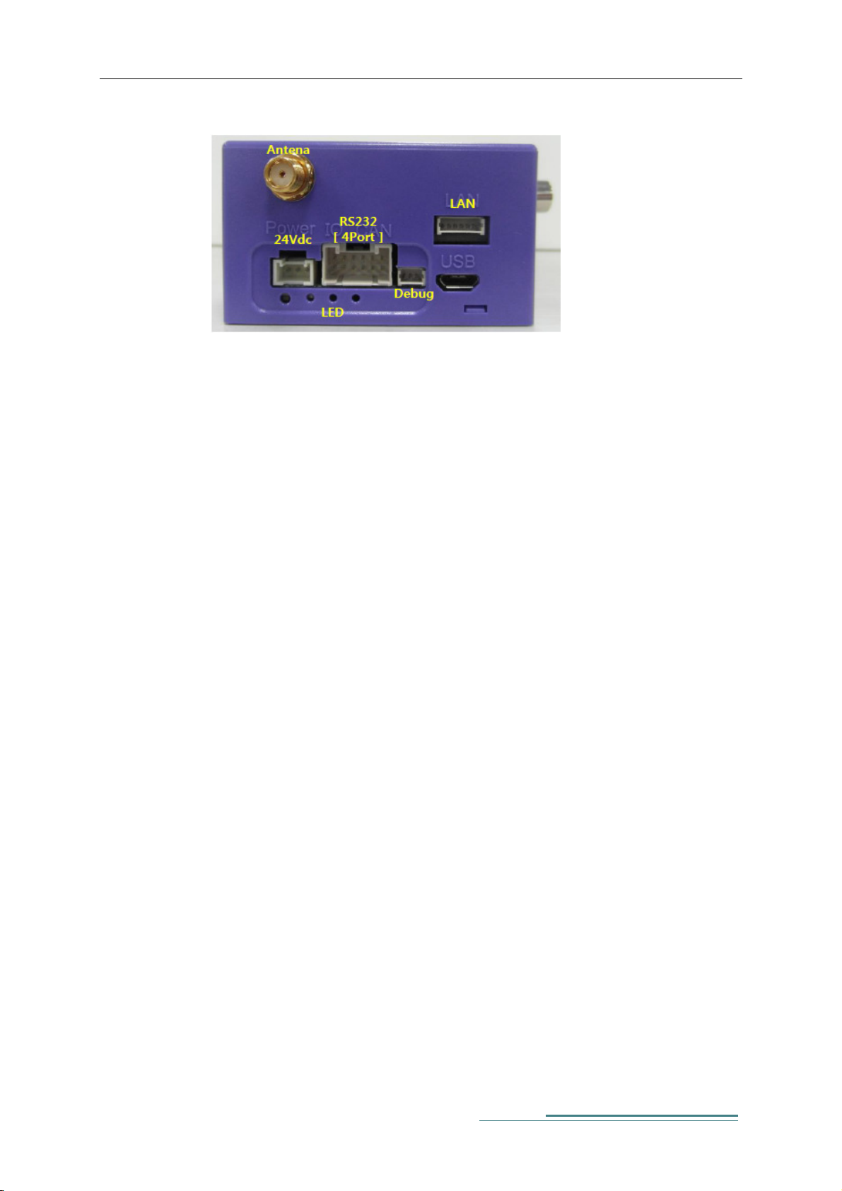
Figure 2 SCOPE2.0 Plus Front Exterior
A. Power : 24Vdc supply ( VCC / GND / FG)
B. Antenna : Port for connecting WI-FI module
C. LAN : LAN Port for Ethernet communication with other devices using
TCP/IP
D. USB : USB-OTG Port ( used for FW update)
E. LED(1,2,3) : Status LED
F. FG : Frame Ground for noise reduction. Connects to host equipment
ground
G. RS232 : standard for serial communication transmission of data ( used
for communication between SCOPE2.0 Plus and equipment)
H. Debug : RS232 Debugging Port
4
 Loading...