

Samsung NE59K3310SW/AA, NE59K3310SS/AA, NE59K3310SB/AA, NE59J7850WS/AA, NE59J7850WG/AA Installation Guide [es, en]
...Page 1
imagine the possibilities
Thank you for purchasing this Samsung product.
Electric Range
installation manual
Install_30_Electric_Range_USA_DG68-00108G-04_EN.indd 1 3/30/2016 10:19:17 PM
Page 2
before you begin
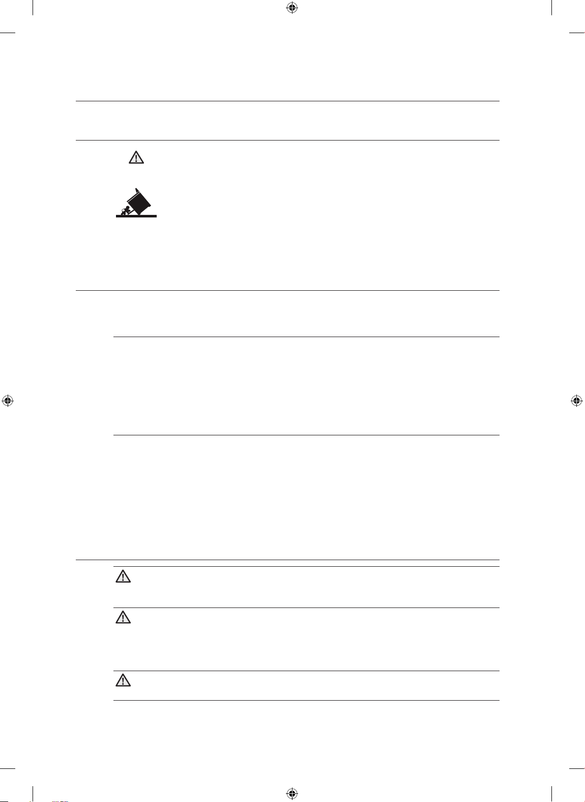
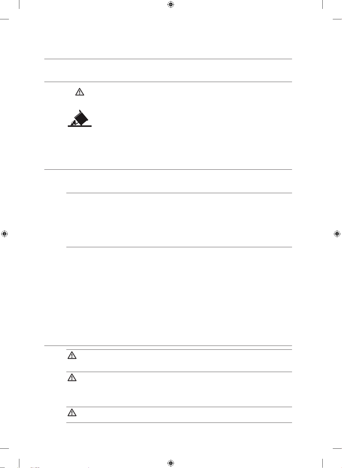
ANTI-TIP DEVICE
WARNING: To reduce the risk of tipping the appliance, the appliance must be
WARNING
ABOUT THIS MANUAL
READ THESE INSTRUCTIONS COMPLETELY AND CAREFULLY.
Important note to the installer
• Read all instructions contained in these installation instructions before installing range.
• Remove all packing materials from the oven compartments before connecting the electrical supply
to the range.
• Observe all governing codes and ordinances.
• Be sure to leave these instructions with the consumer.
secured by properly installed anti-tip devices packed with the appliance.
a) A child or adult can tip the range and be killed.
b) Install the anti-tip device to the structure and/or the range at rear right (or rear left)
of the range bottom.
c) Engage the range to the anti-tip device by leveling leg at rear right (or rear left) of
the range bottom.
d) Re-engage the anti-tip device if the range is moved.
e) See installation instructions for details.
f) Failure to do so can result in death or serious burns to children or adults.
Important note to the consumer
Keep these instructions for the local electrical inspector’s use.
• As when using any appliance generating heat, there are certain safety precautions you should follow.
• Be sure your range is installed and grounded properly by a qualified installer or service technician.
• Make sure the wall coverings around the range can withstand the heat generated by the range.
• To eliminate the need to reach over the surface elements, cabinet storage space above the elements
should be avoided.
• The range should not be placed on a base.
FOR YOUR SAFETY
WARNING
WARNING If the information in this manual is not followed exactly, a fire or electrical
shock may result causing property damage, personal injury or death.
WARNING
WARNING Before beginning the installation, switch power off at the service panel and
lock the service disconnecting means to prevent power from being switched on accidentally. When the
service disconnecting means cannot be locked, securely fasten a prominent warning device, such as a
tag, to the service panel.
WARNING
WARNING This appliance must be properly grounded.
English - 2
Install_30_Electric_Range_USA_DG68-00108G-04_EN.indd 2 3/30/2016 10:19:17 PM
Page 3
preparing to install the range
01
BEFORE YOU BEGIN & PREPARING TO INSTALL THE RANGE
REMOVE PACKAGING
Remove packaging materials. Failure to remove packaging materials could result in damage to the
appliance.
PREPARE TOOLS & PARTS
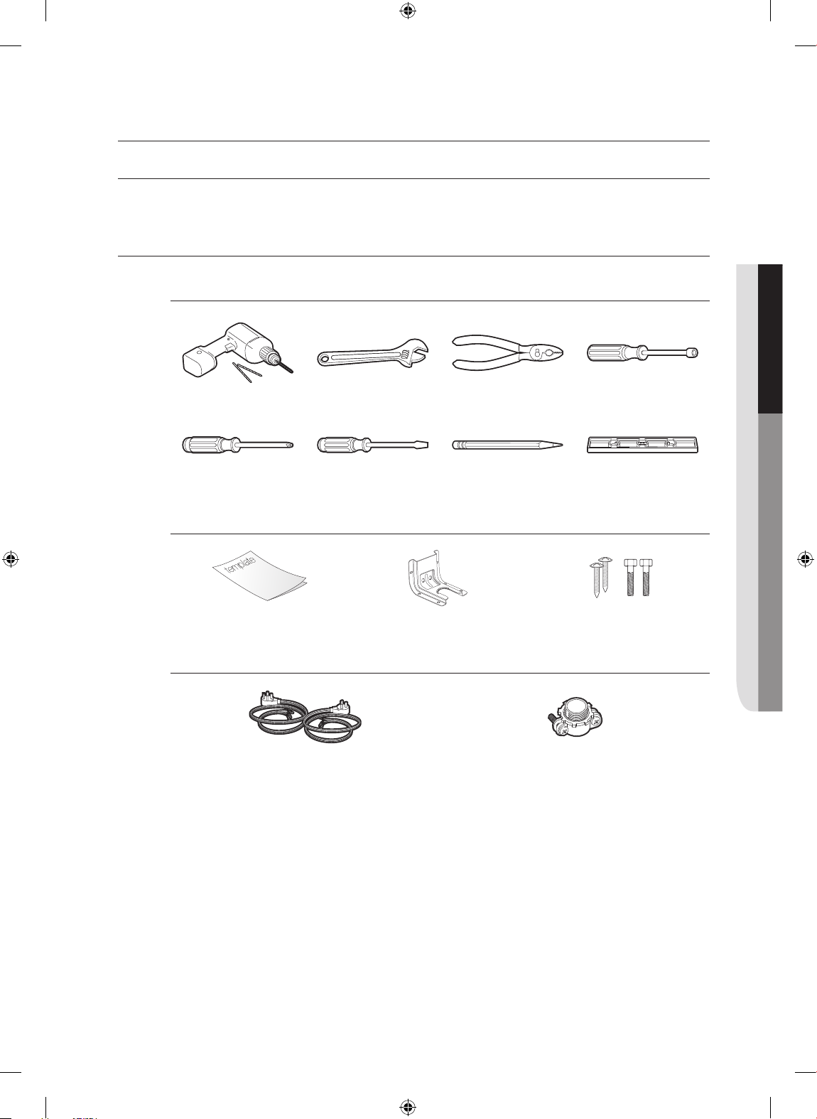
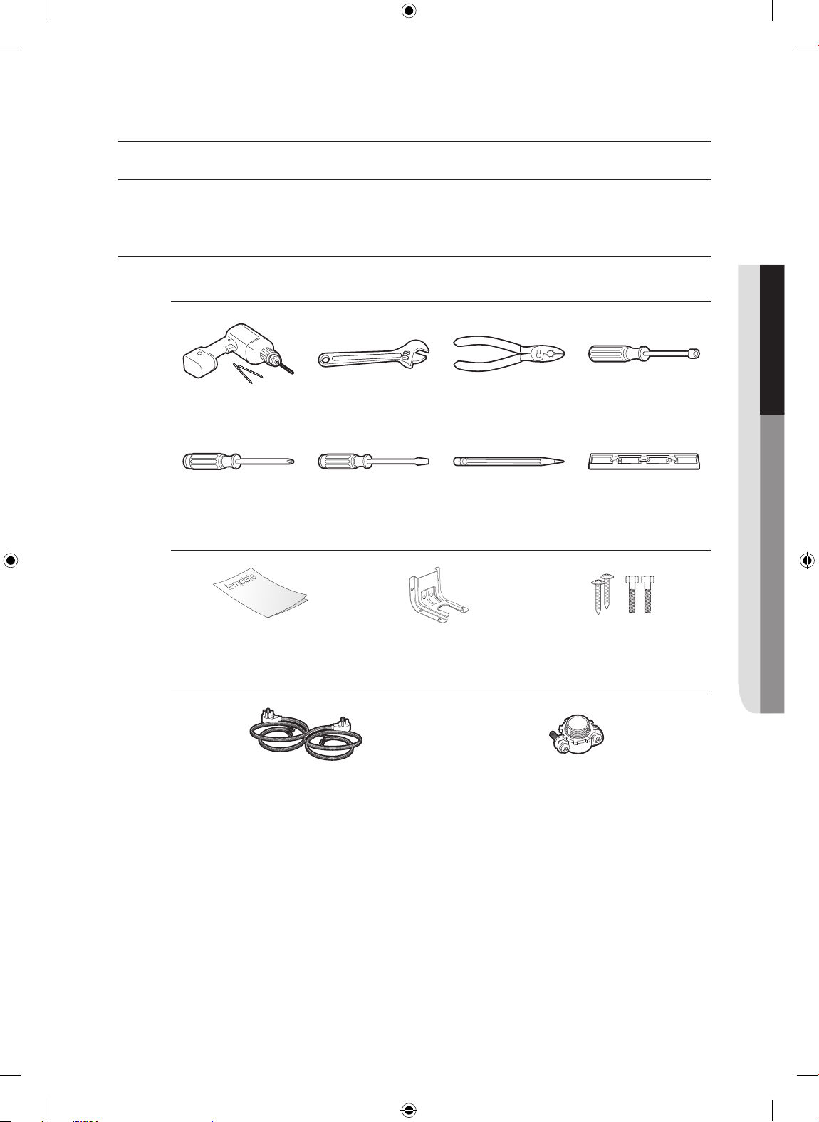
What tools you will need
Drill Adjustable Wrench Pliers
Phillips Screwdriver Flat Screwdriver Pencil Level
1
/4" Nut Driver
What’s included with your range
Template Anti-Tip Bracket Screws (4 ea)
What’s not included
4-Wire Cord or 3-Wire Cord
(UL Approved 40 or 50 AMP)
English - 3
Install_30_Electric_Range_USA_DG68-00108G-04_EN.indd 3 3/30/2016 10:19:18 PM
Strain Relief
(For Conduit Installation Only)
Page 4
CHECKING THE INSTALLATION SITE
Clearances and dimensions
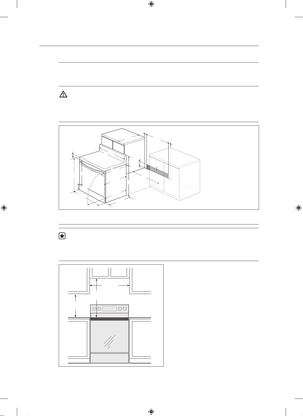
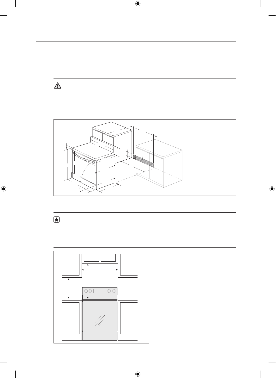
To install the range, refer to the following figure.
For installation in CANADA, a Free-standing range is not to be installed closer than 12mm
from any adjacent surface.
CAUTION
CAUTION This range has been designed to comply with the maximum allowable wood
cabinet temperatures of 194 °F. Make sure the wall covering, countertops and cabinets around the
range can withstand the heat (up to 194 °F) generated by the range. If not, discoloration, delamination
or melting may occur.
3"
25"
24"
3"
1-3/5"
36"~36-4/5"
24-9/10"
7-1/2"
29-4/5"
29-9/10"
28-1/5"
25-9/10"
49-2/5"
24-3/10"
6"
46-1/5" ~ 47"
B
A
A : Cabinet opening
30" For U.S.A,
30"~31" For CANADA.
B : Acceptable
electrical outlet area
Minimum dimensions
IMPORTANT To eliminate the risk of burns or fire caused by reaching over heated surface
units, cabinet storage space located above the surface units should be avoided. If cabinet storage is to
be provided, the risk can be reduced by installing a range hood that projects horizontally a minimum of
5" beyond the bottom of the cabinets.
30"
* 30"
** 15"
* 30" minimum clearance between the top
of the cooking surface and the bottom of
an unprotected wood or metal cabinet;
or 24" minimum when the bottom of the
wood or metal cabinet is protected by not
less than 1/4" flame retardant millboard
covered with not less than no.28 MSG
sheet steel, 0.015" stainless steel, 0.024"
aluminum or 0.020" copper.
** 15" minimum between the countertop and
the adjacent cabinet bottom.
English - 4
Install_30_Electric_Range_USA_DG68-00108G-04_EN.indd 4 3/30/2016 10:19:19 PM
Page 5
connecting the power
02 CONNECTING THE POWER
STEP 1. MEETING ELECTRICAL CONNECTION REQUIREMENTS
CAUTION
CAUTION For personal safety, do not use an extension cord with this appliance.
Remove house fuse or open circuit breaker before beginning installation.
This appliance must be supplied with the proper voltage and frequency, and
connected to an individual properly grounded branch circuit, protected by a
circuit breaker or fuse having amperage as specified on the rating plate. The
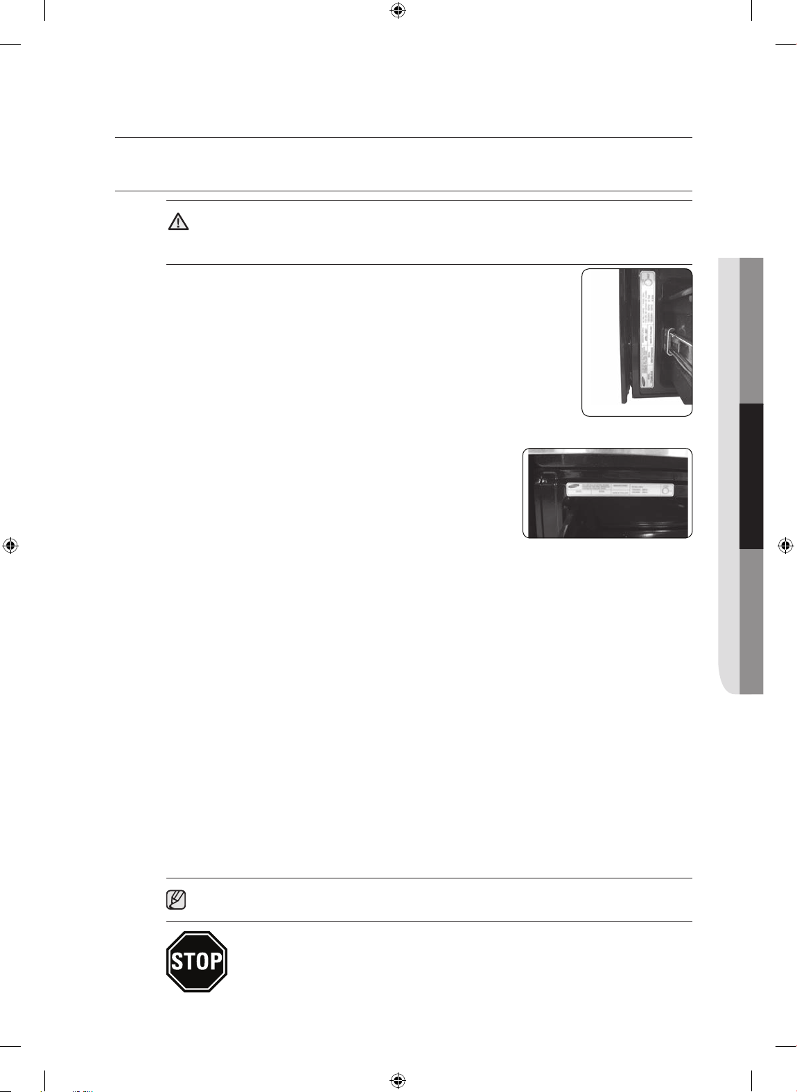
rating plate is located above the drawer on the oven frame. (Fig. 1 or Fig. 2)
We recommend you have the electrical wiring and hookup of your range
connected by a qualified electrician. After installation, have the electrician show
you where your main range disconnect is located.
Check with your local utilities for electrical codes which apply in your area.
Failure to wire your oven according to governing codes could result in a
hazardous condition. If there are no local codes, your range must be wired and
fused to meet the requirements of the National Electrical Code, ANSI/NFPA No.
70–Latest Edition. You can get a copy by writing:
National Fire Protection Association
Batterymarch Park
Quincy, MA 02269
(Fig. 1)
(Fig. 2)
Effective January 1, 1996, the National Electrical Code requires that new construction (not
existing) utilize a 4-conductor connection to an electric range.
When installing an electric range in new construction, follow Steps 2 and 3 for 4-wire
connection.
You must use a 3-wire or 4-wire, single-phase A.C. 208Y/120 Volt or 240/120 Volt, 60 hertz electrical
system.
If the electrical service provided does not meet the above specifications, have a licensed electrician
install an approved outlet.
Use only a 3-conductor or a 4-conductor UL-listed range cord. These cords may be provided with ring
terminals on wire and a strain relief device.
A range cord rated at 40 amps with 125/250 minimum volt range is required. A 50 amp range cord
is not recommended but if used, it should be marked for use with nominal 1
openings. Care should be taken to center the cable and strain relief within the knockout hole to keep
the edge from damaging the cable.
• Because range terminals are not accessible after range is in position, flexible service conduit or cord
must be used.
NOTE If conduit is being used, go to Step 4 on page 9.
ALL NEW BRANCH-CIRCUIT CONSTRUCTIONS, MOBILE HOMES,
RECREATIONAL VEHICLES AND INSTALLATIONS WHERE LOCAL CODES DO
NOT ALLOW GROUNDING THROUGH NEUTRAL, REQUIRE A 4-CONDUCTOR
UL-LISTED RANGE CORD.
3
⁄8" diameter connection
English - 5
Install_30_Electric_Range_USA_DG68-00108G-04_EN.indd 5 3/30/2016 10:19:19 PM
Page 6
STEP 2. ACCESSING THE POWER CORD CONNECTION
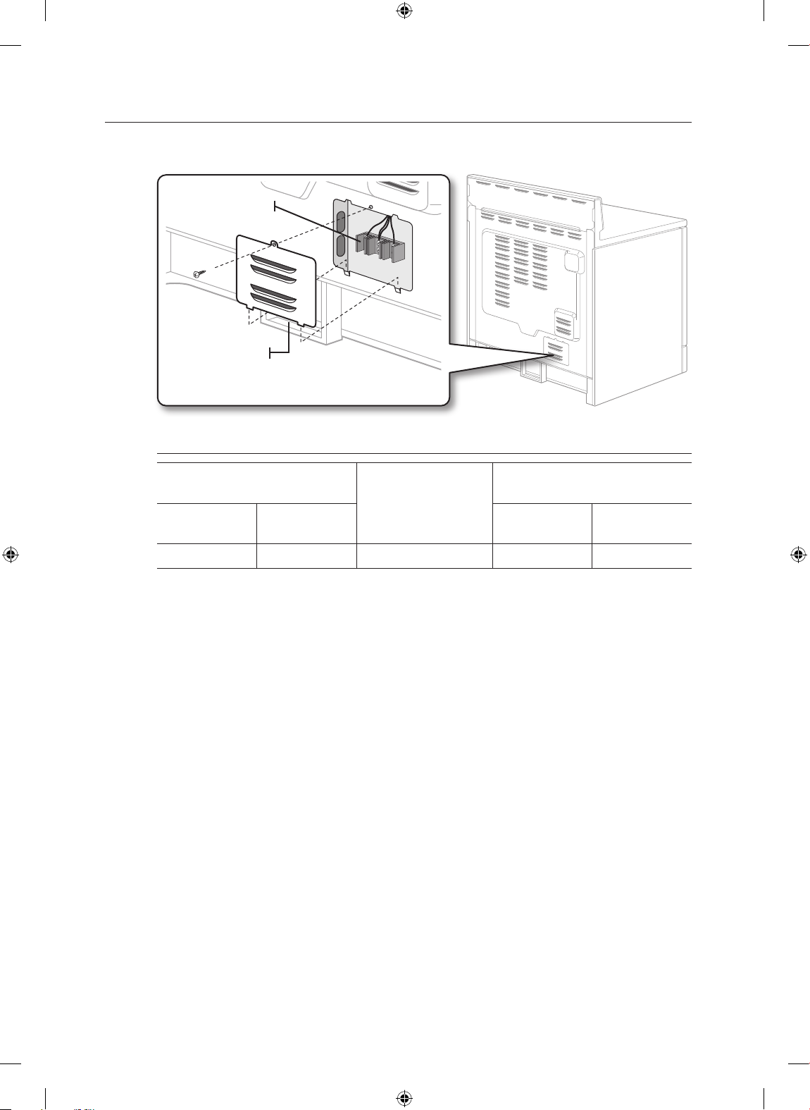
Remove the rear access cover and loosen the screw with a screwdriver. The terminal block will then be
accessible.
Terminal block
Access cover
Specified power-supply-cord kit rating
Range rating, watts
120 / 240 volts
3-wire
8,750 - 16,500 7,801 - 12,500 40 or 50A 1
120 / 208 volts
3-wire
Specified rating of
power-supply-cord kit,
amperes
Diameter (inches) of range
Power cord Conduit
connection opening
3
/8" 11/8"
English - 6
Install_30_Electric_Range_USA_DG68-00108G-04_EN.indd 6 3/30/2016 10:19:19 PM
Page 7
STEP 3. INSTALLING THE POWER CORD
02 CONNECTING THE POWER
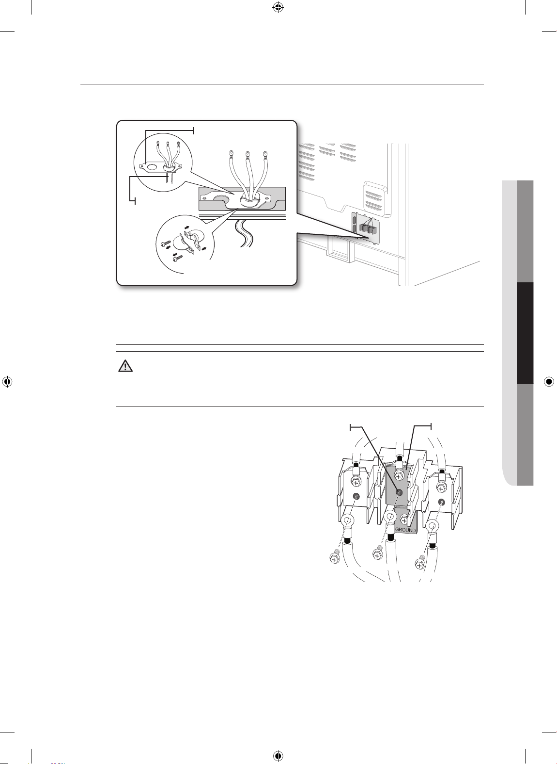
For power cord installations, hook the strain relief over the power cord hole (13/8") located below the
rear of the drawer body. Insert the power cord through the strain relief and tighten the device.
Conduit connection plate
Power cord
Strain relief
• You must install the power cord with a strain relief.
3
• Attach the strain relief to the 1
/8" opening in conduit connection plate.
Installing a 3-wire power cord
WARNING
WARNING The neutral or ground wire of the power cord must be connected to the
neutral terminal located in the center of the terminal block. The power leads must be connected to the
lower left and the lower right terminals of the terminal block.
1. Remove the 3 lower terminal screws from the
terminal block.
2. Insert the 3 terminal screws through each
power cord terminal ring and into the lower
terminals of the terminal block. Be certain that
the center wire (white/neutral) is connected to
the center lower position of the terminal block.
3. Tighten screws securely into the terminal
block. DO NOT remove the ground strap
connection.
4. Go to step 5 on page 10 and proceed with
the installation.
Neutral
terminal
White
Black
Ground strap
Red
Black
White
Red
English - 7
Install_30_Electric_Range_USA_DG68-00108G-04_EN.indd 7 3/30/2016 10:19:20 PM
Page 8
Installing a 4-wire power cord
WARNING
WARNING The neutral wire of the supply circuit must be connected to the neutral terminal
located in the lower center of the terminal block. The power leads must be connected to the lower left
and the lower right terminals of the terminal block. The 4th grounding lead must be connected to the
frame of the range with the ground plate and the ground screw.
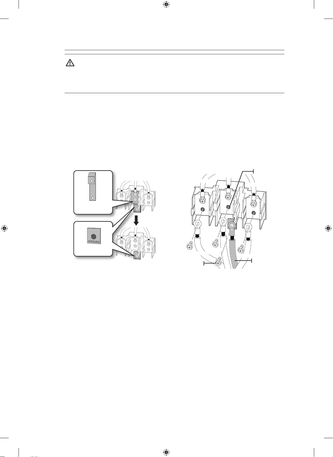
1. Remove the 3 lower terminal screws from the terminal block. Remove the ground screw and
ground plate and retain them.
2. Cut and discard the ground strap. Do not discard any screws.
3. Insert the one ground screw into the power cord ground wire terminal ring, through the ground
plate, and into the frame of the range.
4. Insert the 3 terminal screws (removed earlier) through each power cord terminal ring and into the
lower terminals of the terminal block. Be certain that the center wire (white/neutral) is connected
to the center lower position of the terminal block. Tighten screws securely into the terminal block.
5. Go to step 5 on page 10 and proceed with the installation.
Ground strap
Ground plate
Black
Ground
screw
Black
White
White
Neutral
terminal
Red
Red
Ground
wire (Green)
English - 8
Install_30_Electric_Range_USA_DG68-00108G-04_EN.indd 8 3/30/2016 10:19:20 PM
Page 9
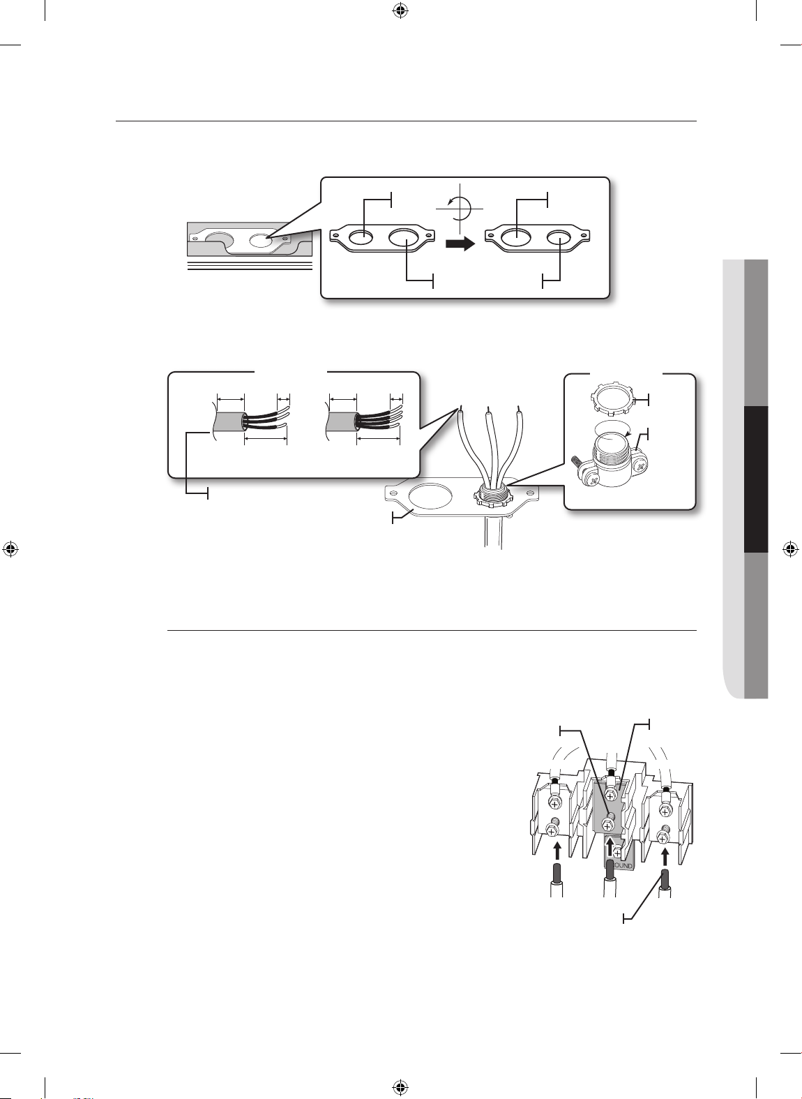
STEP 4. INSTALLING THE CONDUIT
02 CONNECTING THE POWER
Remove the conduit connection plate from the rear of the drawer body and rotate it as shown below.
1
The conduit hole (1
1. Prepare the conduit cord shown in Figure 1.
2. Install the conduit cord as shown in Figure 2.
/8") must be used.
1
1
/8" 13/8"
1
1
/8"13/8"
Figure 2
1"
Figure 1
3
/8" 1"
3
/8"
Ring
1
3
/2"
1
3
/2"
Body
3 wire 4 wire
Knockout surface
Strain relief
Conduit connection plate
1
For conduit installations, insert the strain relief (not included) into the conduit hole (1
/8"). Then thread
the conduit cord through the body of the strain relief and fasten the ring. Reinstall the bracket.
Installing a 3-wire conduit
• Aluminum building wire may be used but it must be rated for the correct amperage and voltage to
make the connection. Connect wires according to Step 4 depending on the number of wires.
• Wire used, location and enclosure of splices, etc., must conform to good wiring practices and local
codes.
1. Loosen the 3 lower terminal screws from the terminal
block.
2. Insert the center bare wire (white/neutral) tip through
the bottom center terminal block opening. On certain
models, the wire will need to be inserted through the
ground strap opening and then into the bottom center
block opening.
3. Insert the two side bare wire tips into the lower left
and the lower right terminal block openings.
4. Tighten the screws until the wire is firmly secured (35
to 50 inch-lbs.). Do not over-tighten the screws since
it could damage the wires.
5. Go to step 5 on page 10 and proceed with the
installation.
Neutral
terminal
Black
Black
White
White
Wire tips
Ground
strap
Red
Red
English - 9
Install_30_Electric_Range_USA_DG68-00108G-04_EN.indd 9 3/30/2016 10:19:20 PM
Page 10
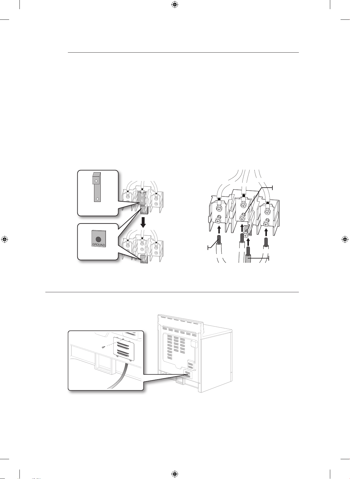
Installing a 4-wire conduit
• Aluminum building wire may be used but it must be rated for the correct amperage and voltage to
make the connection. Connect wires according to this Step 4 depending on the number of wires.
• Wire used, location and enclosure of splices, etc., must conform to good wiring practices and local
codes.
1. Loosen the 3 lower terminal screws from the terminal block. Remove the ground screw and
ground plate and retain them.
2. Cut and discard the ground strap. Do not discard any screws.
3. Insert the ground bare wire tip between the range frame and the ground plate (removed earlier)
and secure it in place with the ground screw (removed earlier).
4. Insert the bare wire (white/neutral) tip through the bottom center of the terminal block opening.
5. Insert the two side bare wire tips into the lower left and the lower right terminal block openings.
6. Tighten the screws until the wire is firmly secured (35 to 50 inch-lbs.). Do not over-tighten the
screws since it could damage the wires.
7. Go to step 5 and proceed with the installation.
Ground strap
Wire tips
Ground plate
STEP 5. REPLACING THE ACCESS COVER
Replace the access cover on the range back. To replace the wire cover, insert double projections in the
pockets located below the opening and tighten the screw.
Black
Black
White
White
Red
Neutral
terminal
Red
Ground
wire (Green)
English - 10
Install_30_Electric_Range_USA_DG68-00108G-04_EN.indd 10 3/30/2016 10:19:21 PM
Page 11
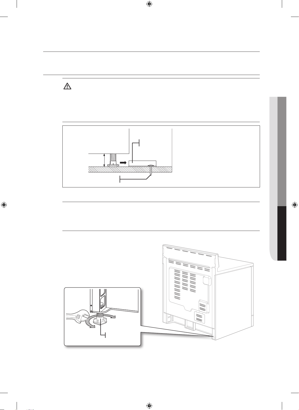
installing the range
03 INSTALLING THE RANGE
INSTALLING THE ANTI-TIP DEVICE
WARNING
WARNING To reduce the risk of tipping, the appliance must be secured by properly
installing the Anti-Tip device packed with the appliance.
• Refer to the installation instructions supplied with the bracket.
• Unless properly installed, the range could be tipped by stepping or sitting on the door. Injury may
result from spilled hot liquids or from the range itself.
Anti-Tip
bracket
*approximately
21/32"(16.5mm)
Screw must enter wood or
concrete
*NOTE: To install Anti-Tip bracket,
release the leveling leg. A minimum
clearance of 21/32"(16.5mm) is required
between the range bottom and the
kitchen floor.
1. Locate the bracket using the template
The Anti-Tip bracket is packaged with a template. The instructions include information necessary to
complete the installation. Read and follow the instructions on the sheet (template) for range installation.
2. Level the range
Level the range by adjusting the leveling legs with a wrench.
Raise range
Lower range
Leveling leg
English - 11
Install_30_Electric_Range_USA_DG68-00108G-04_EN.indd 11 3/30/2016 10:19:21 PM
Page 12
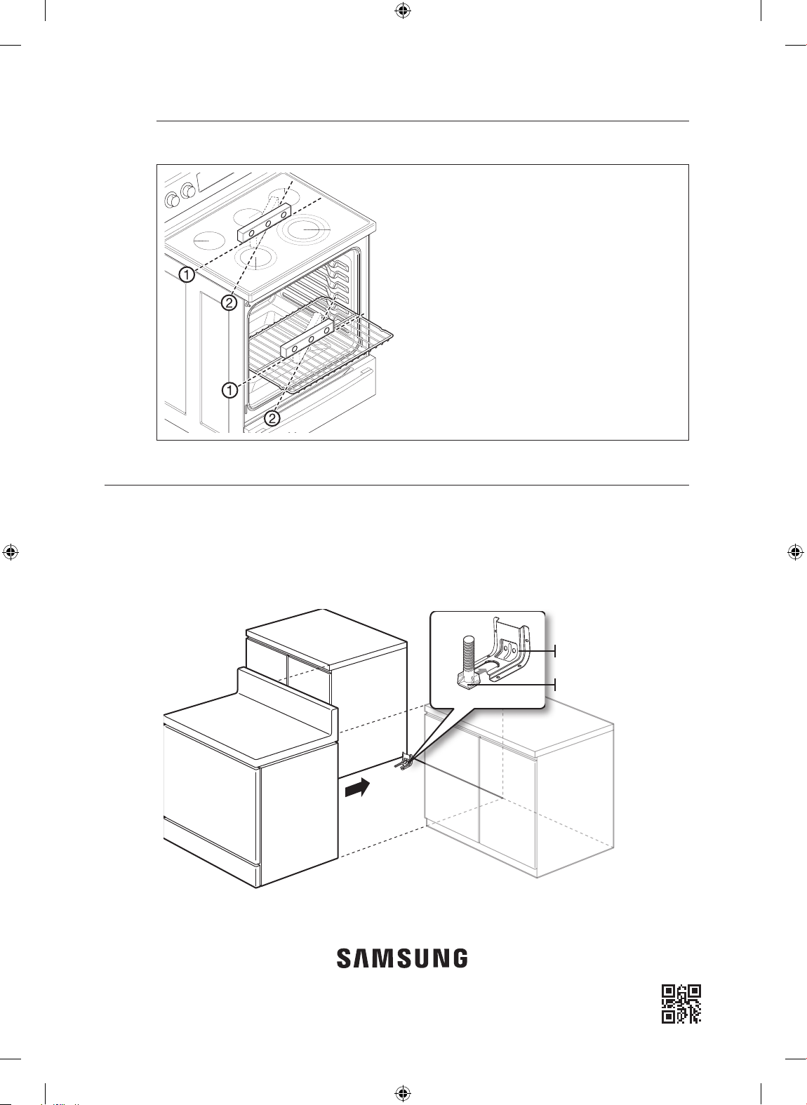
3. Check your adjustments
Use a spirit level to check your adjustments. Place the level diagonally on the oven rack or surface
cooktop, and check each direction for level.
FINALIZING THE INSTALLATION
• Move range close enough to the opening to plug into the receptacle.
• Slide range into position insuring that the rear left(or rear right) leg slides under the Anti-Tip bracket.
The range will sit 0" away from the back wall when properly installed.
• Carefully tip the range forward to insure that the Anti-Tip bracket engages the back brace and
prevents tip-over.
• Turn on the electrical power. Check the range for proper operation as described in the user manual.
1. Check direction 1.
2. Check direction 2.
If the spirit level doesn’t show level on the oven
rack or surface cooktop, adjust the leveling legs
with a wrench.
English - 12
Anti-Tip bracket
Leveling leg
DG68-00108G-04
Install_30_Electric_Range_USA_DG68-00108G-04_EN.indd 12 3/30/2016 10:19:22 PM
Page 13
imagine las posibilidades
Gracias por adquirir este producto Samsung.
Estufa eléctrica
manual de instalación
Install_30_Electric_Range_USA_DG68-00108G-04_MES.indd 1 3/30/2016 10:21:00 PM
Page 14
antes de comenzar
DISPOSITIVO ANTI INCLINACIÓN
ADVERTENCIA: Para reducir el riesgo de inclinaciones, el artefacto debe quedar correctamente
ADVERTENCIA
ACERCA DE ESTE MANUAL
LEA ESTAS INSTRUCCIONES EN SU TOTALIDAD Y CUIDADOSAMENTE.
Nota importante para el instalador
• Lea todas las instrucciones contenidas en este manual antes de instalar la estufa.
• Retire de la estufa todos los materiales de empaque de los compartimientos del horno antes de
conectar la alimentación eléctrica a la estufa.
• Cumpla todos los códigos y ordenanzas exigidos por las autoridades pertinentes.
• Asegúrese de dejar estas instrucciones con el usuario final.
fijado mediante la instalación de los dispositivos anti inclinación que vienen con el equipo.
a) Un niño o un adulto podrían inclinar la estufa y morir.
b) Instale el dispositivo anti inclinación en la estructura y/o en la parte posterior derecha
(o posterior izquierda) de la base de la estufa.
c) Acople la estufa en el dispositivo anti inclinación nivelando las patas en la parte posterior
derecha (o posterior izquierda) de la base de la estufa.
d) Vuelva a acoplar el dispositivo anti inclinación en caso de mover la estufa.
e) Consulte las instrucciones de instalación para obtener más información.
f) No hacerlo puede provocar la muerte o quemaduras serias a niños o adultos.
Nota importante para el usuario final
Guarde estas instrucciones para que puedan ser consultadas por el inspector del servicio
eléctrico de su localidad.
• Como con cualquier electrodoméstico que genera calor, existen ciertas precauciones de seguridad que
se deben cumplir.
• Asegúrese de que su electrodoméstico sea correctamente instalado y conectado a tierra por un técnico
calificado.
• Asegúrese de que los revestimientos de las paredes alrededor de la estufa pueden soportar el calor que
ésta genera.
• Para evitar tener que alcanzar objetos por encima de los elementos radiantes de la superficie, se
desaconseja la instalación de gabinetes de almacenamiento en el espacio arriba de tales elementos.
• La estufa no debe colocarse sobre una base.
PARA SU SEGURIDAD
ADVERTENCIA
ADVERTENCIA Si la información de este manual no es seguida con exactitud, se podrían
producir incendios o descargas eléctricas causantes de daños a la propiedad, lesiones personales, o la muerte.
ADVERTENCIA
ADVERTENCIA Antes de comenzar la instalación, corte la alimentación eléctrica desde el panel
de servicio y cierre con llave el dispositivo de desconexión para evitar que la corriente eléctrica sea conectada
accidentalmente. Si resulta imposible cerrar con llave el dispositivo de desconexión del servicio, fije en forma
segura sobre el panel de servicio alguna forma muy notoria de advertencia, tal como un cartel o marbete.
ADVERTENCIA
ADVERTENCIA Este electrodoméstico debe conectarse debidamente a tierra.
Español - 2
Install_30_Electric_Range_USA_DG68-00108G-04_MES.indd 2 3/30/2016 10:21:00 PM
Page 15
preparación para instalar la estufa
01 ANTES DE COMENZAR Y PREPARACIÓN PARA INSTALAR LA ESTUFA
RETIRE EL MATERIAL DE EMPAQUE
Retire el material de empaque. No retirar los materiales de empaque podría causar daños al
electrodoméstico.
PREPARE LAS HERRAMIENTAS Y LAS PIEZAS
Las herramientas que necesitará.
Taladro Llave ajustable Pinzas Desarmador de caja
para tuercas de 1/4
Desarmador Phillips Desarmador plano Lápiz Nivel
Elementos incluidos con su estufa
Plantilla Ménsula anti inclinación Tornillos (4 unid.)
Elementos no incluidos con su estufa
"
Cable de 4 conductores o
cable de 3conductores
(de 40 o 50 AMP,
aprobados por United Laboratories, Inc. ("UL"))
Español - 3
Install_30_Electric_Range_USA_DG68-00108G-04_MES.indd 3 3/30/2016 10:21:01 PM
Sujetador de cables con amortiguador de
esfuerzo
(únicamente para instalación con conducto)
Page 16
INSPECCIÓN DEL SITIO DE INSTALACIÓN
Distancias, espacios libres y dimensiones
Para instalar la estufa, observe la figura a continuación.
Para instalaciones en CANADÁ, una estufa de pie no debe instalarse a menos de 12 mm de
cualquier superficie adyacente.
PRECAUCIÓN
PRECAUCIÓN Esta estufa ha sido diseñada para cumplir con la temperatura máxima
admisible para gabinetes de madera de 194 °F. Asegúrese de que los revestimientos de paredes,
superficies de mesada y gabinetes alrededor de la estufa puedan soportar el calor (hasta 194 °F)
generado por la estufa. De lo contrario, se podrían producir alteraciones de color, deslaminación o
derretimiento.
3"
25"
24"
3"
1-3/5"
36"~36-4/5"
24-9/10"
7-1/2"
29-4/5"
29-9/10"
28-1/5"
25-9/10"
49-2/5"
24-3/10"
6"
46-1/5" ~ 47"
B
A
A: Espacio entre
gabinetes
30 pulgadas para los
EE. UU.,
30~31 pulgadas para
CANADÁ.
ea admisible para
B: Ár
toma de corriente
Dimensiones mínimas
IMPORTANTE Para eliminar el riesgo de quemaduras o de incendio provocado
por contacto con las unidades sobrecalentadas en superficie, debe evitarse colocar gabinetes
de almacenamiento por encima de las unidades de superficie. Si deben instalarse gabinetes de
almacenamiento, el riesgo puede reducirse instalando una campana para estufas que se proyecte
horizontalmente por lo menos 5" más allá de la parte inferior de los gabinetes.
30"
* 30"
** 15"
* Separación mínima de 30 pulgadas
entre el extremo superior de la superficie
de cocción y el extremo inferior de un
gabinete de madera o metal no protegido;
mínima de 24 pulgadas cuando el extremo
inferior del gabinete de madera o metal
está protegido por un tablero ignífugo de
un mínimo de 1/4" cubierto con una lámina
de acero Nro. 28, como mínimo, 0.015"
de acero inoxidable, 0.024" de aluminio o
0.020" de cobre.
** 15" como mínimo entre la superficie de la
mesada y la parte inferior del gabinete más
cercano.
Español - 4
Install_30_Electric_Range_USA_DG68-00108G-04_MES.indd 4 3/30/2016 10:21:01 PM
Page 17
cómo conectar la corriente eléctrica
02 CONEXIÓN A LA CORRIENTE ELÉCTRICA
PASO 1. CUMPLIMIENTO DE LAS EXIGENCIAS DE CONEXIÓN ELÉCTRICA
PRECAUCIÓN
PRECAUCIÓN Para seguridad de las personas, no utilice cables prolongadores con este
electrodoméstico. Quite el fusible de su casa o corte la electricidad con el disyuntor antes de comenzar la instalación.
Este electrodoméstico debe ser alimentado con el voltaje y la frecuencia correctos, y debe
conectarse a un ramal de circuito individual correctamente conectado a tierra y protegido
con un disyuntor o fusible cuyo amperaje debe concordar con lo establecido en la placa de
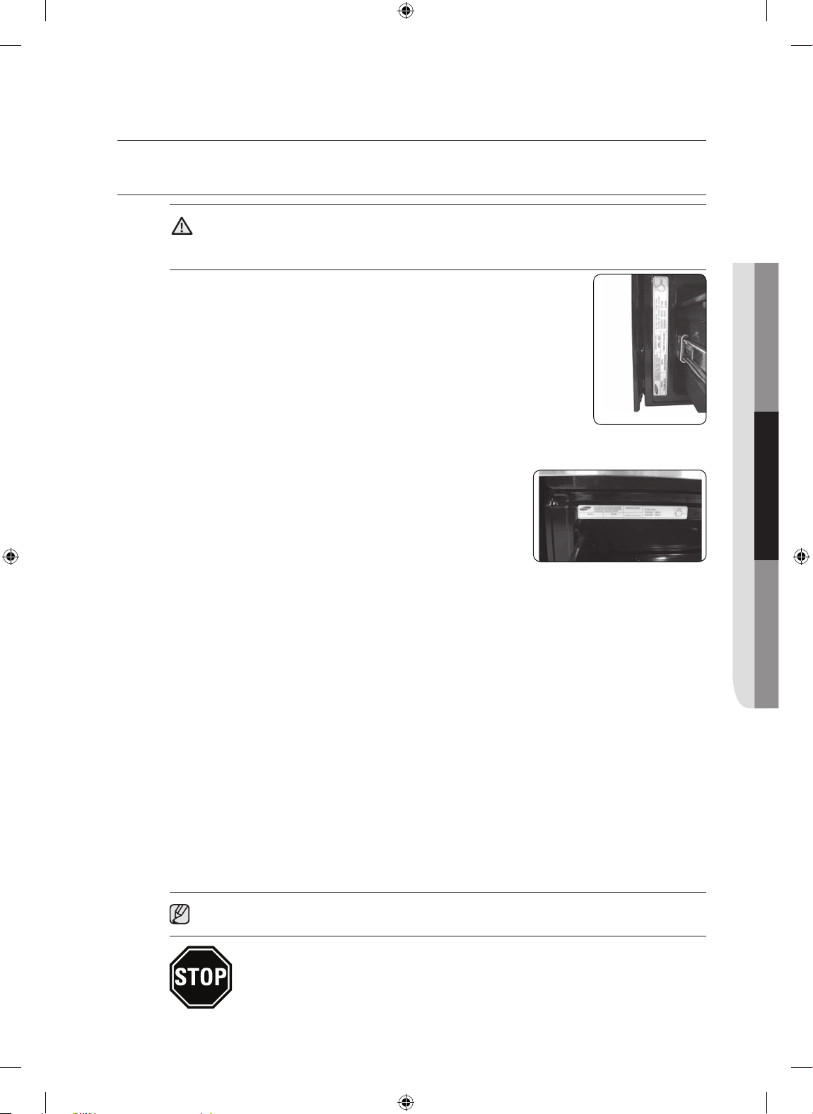
especificaciones. La placa de especificaciones se encuentra ubicada arriba del cajón en el
marco del horno. (Fig. 1 o Fig. 2)
Le recomendamos que el cableado y la conexión de su estufa sean realizados por un
electricista calificado. Luego de la instalación, solicítele al electricista que le muestre dónde se
encuentra el principal dispositivo de desconexión de su estufa.
Verifique con su empresa local de servicio eléctrico los códigos eléctricos vigentes en su área.
Si el cableado de su horno no se hace de acuerdo con los códigos en vigencia se podrían
generar condiciones peligrosas. Si no hay códigos locales, su estufa debe ser cableada y
equipada con fusibles que cumplan los requisitos del National Electrical Code, ANSI/NFPA No.
70–Latest Edition. Para obtener una copia, escriba a:
National Fire Protection Association
Batterymarch Park
Quincy, MA 02269
(Fig. 1)
(Fig. 2)
Con vigencia a partir del 1 de enero de 1996, el National Electrical Code (Código Eléctrico Nacional) exige que
en las construcciones nuevas (no existentes en ese momento) para estufas de cocina se utilicen conexiones
de cuatro conductores.
Cuando instale una estufa eléctrica en una construcción nueva, siga los Pasos 2 y 3 para conexión de
4conductores.
Debe usar un sistema eléctrico de 3 o 4 conductores, monofásico, CA. 208Y/120 voltios o 240/120 voltios, 60 hertz.
Si el servicio eléctrico provisto no cumple con las especificaciones anteriores, haga que un electricista con licencia le
instale un tomacorriente aprobado.
Utilice únicamente un cable para estufas de 3 o 4 conductores incluido en las listas de UL. Estos cables pueden venir con
terminales de aro y un dispositivo de sujeción con amortiguador de esfuerzo.
Se requiere un cable para estufas apto para 40 amps. con un rango de voltaje mínimo de 125/250 voltios.
No se recomienda el uso de cables de 50 amps., pero si se lo utiliza debe estar marcado para uso con aberturas de
conexión de 1
esfuerzo dentro del orificio de salida para evitar que el borde dañe el cable.
• Dado que las terminales no quedan accesibles una vez que la estufa está en posición, se debe usar conducto o cable
flexible.
3
⁄8 pulgadas de diámetro. Se debe prestar cuidado de centrar el cable y el sujetador con amortiguador de
NOTA Si se utiliza un conducto, vaya al Paso 4 en la página 9.
TODAS LAS NUEVAS CONSTRUCCIONES DE CIRCUITOS RAMALES, CASAS RODANTES,
VEHÍCULOS RECREATIVOS E INSTALACIONES DONDE LOS CÓDIGOS LOCALES NO
PERMITEN LA CONEXIÓN A TIERRA MEDIANTE EL NEUTRO, REQUIEREN UN CABLE
PARA ESTUFAS DE 4 CONDUCTORES INCLUIDOS EN LOS LISTADOS DE UL.
Español - 5
Install_30_Electric_Range_USA_DG68-00108G-04_MES.indd 5 3/30/2016 10:21:02 PM
Page 18
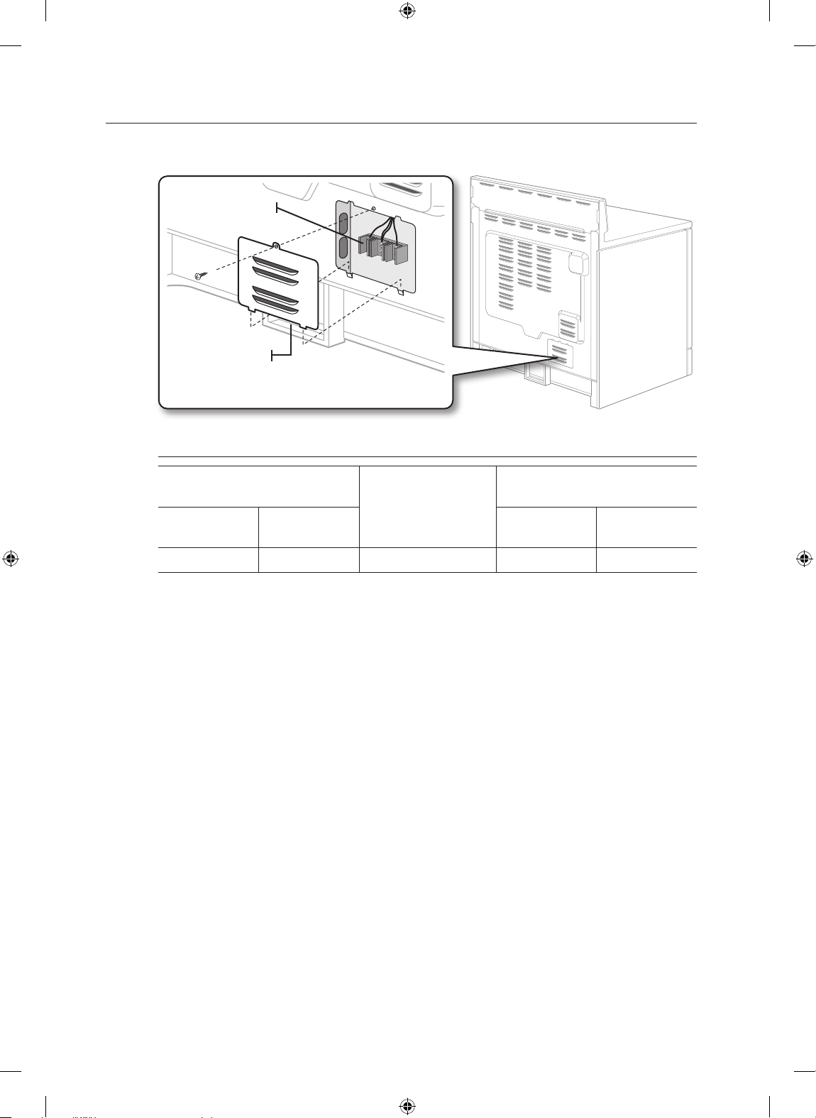
PASO 2. CÓMO ACCEDER A LA CONEXIÓN DEL CABLE DE ALIMENTACIÓN ELÉCTRICA
Retire la cubierta de acceso de la parte posterior y afloje el tornillo con un desarmador. Habrá quedado
abierto el acceso al cuerpo de terminales.
Cuerpo de
terminales
Cubierta de acceso
Especificaciones del kit de cable para alimentación eléctrica.
Especificación de estufa, watts
120 / 240 voltios
3-conductores
8750-16500 7801-12500 40 o 50 A 1
120 / 208 voltios
3-conductores
Especificaciones del
kit de cable para
alimentación eléctrica,
en amperes.
abertura para conexión de la estufa
Diámetro (en pulgadas) de la
Cable de la
alimentación
3
/8" 11/8"
Conducto
Español - 6
Install_30_Electric_Range_USA_DG68-00108G-04_MES.indd 6 3/30/2016 10:21:02 PM
Page 19
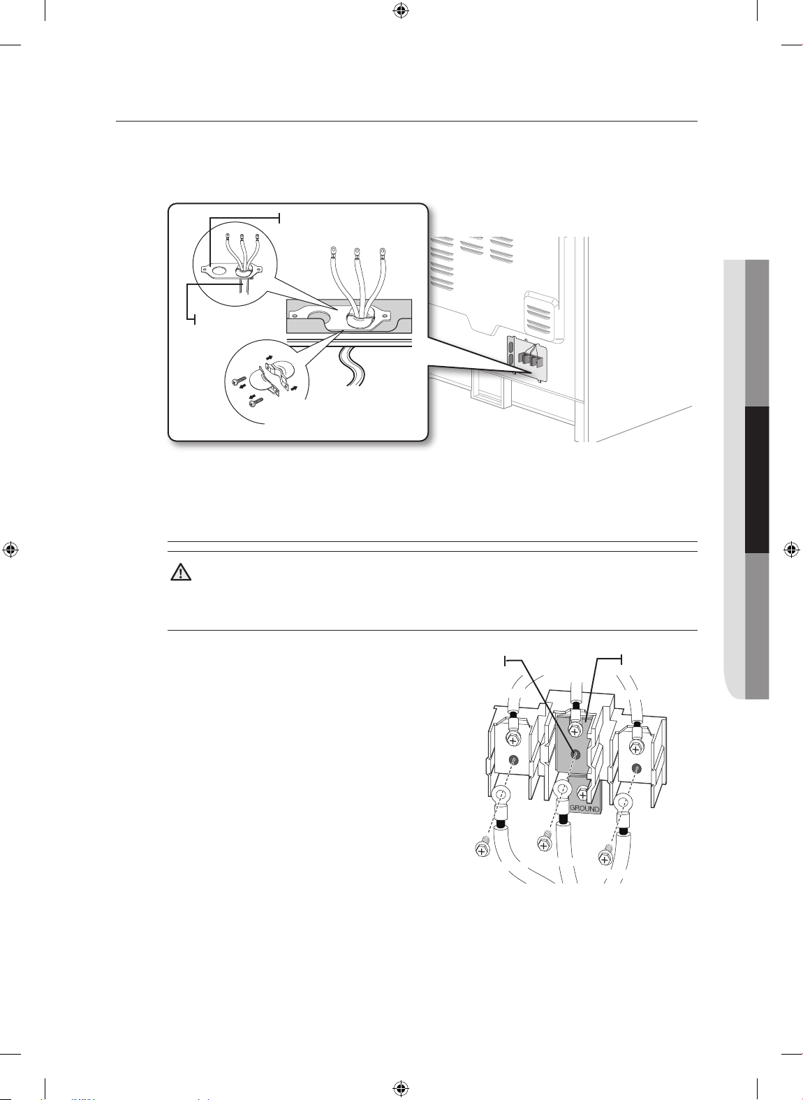
PASO 3. INSTALACIÓN DEL CABLE DE ALIMENTACIÓN ELÉCTRICA
02 CONEXIÓN A LA CORRIENTE ELÉCTRICA
Cuando se realicen instalaciones de cables de alimentación, enganche el sujetador de cables con
amortiguador de esfuerzo sobre el orificio del cable de alimentación (13/8") ubicado debajo de la parte
trasera del cuerpo del cajón. Inserte el cable de alimentación atravesando el sujetador-amortiguador y
ajuste el dispositivo.
Placa de conducción
del conducto
Cable de la
alimentación
Sujetador de cable con
amortiguador de esfuerzo
• El cable de alimentación se debe instalar con un sujetador-amortiguador.
3
• Fije el sujetador de cables con amortiguador de esfuerzo a la abertura de 1
conexión del conducto.
/8" en la placa de
Instalación de un cable de alimentación de 3 conductores
ADVERTENCIA
ADVERTENCIA El conductor neutral o de tierra del cable de alimentación debe conectarse
a la terminal neutra ubicada en el centro del cuerpo de terminales. Los chicotes de cable que portan
corriente deben conectarse a las terminales inferior izquierda e inferior derecha del cuerpo de terminales.
1. Retire los tornillos de las tres terminales
inferiores del cuerpo de terminales.
2. Introduzca los 3 tornillos terminales a
través de cada aro terminal del cable de
alimentación y dentro de las terminales
inferiores del cuerpo de terminales. Asegúrese
de que el conductor central (blanco/neutro)
sea conectado a la posición central inferior
del cuerpo de terminales.
3. Ajuste los tornillos al cuerpo de terminales
en forma segura. NO retire la cinta de
conexión a tierra.
4. Vaya al paso 5 en la página 10 y continúe
con la instalación.
Terminal
neutra
Negro
Negro
Blanco
Blanco
Cinta de
conexión a tierra
Rojo
Rojo
Español - 7
Install_30_Electric_Range_USA_DG68-00108G-04_MES.indd 7 3/30/2016 10:21:02 PM
Page 20
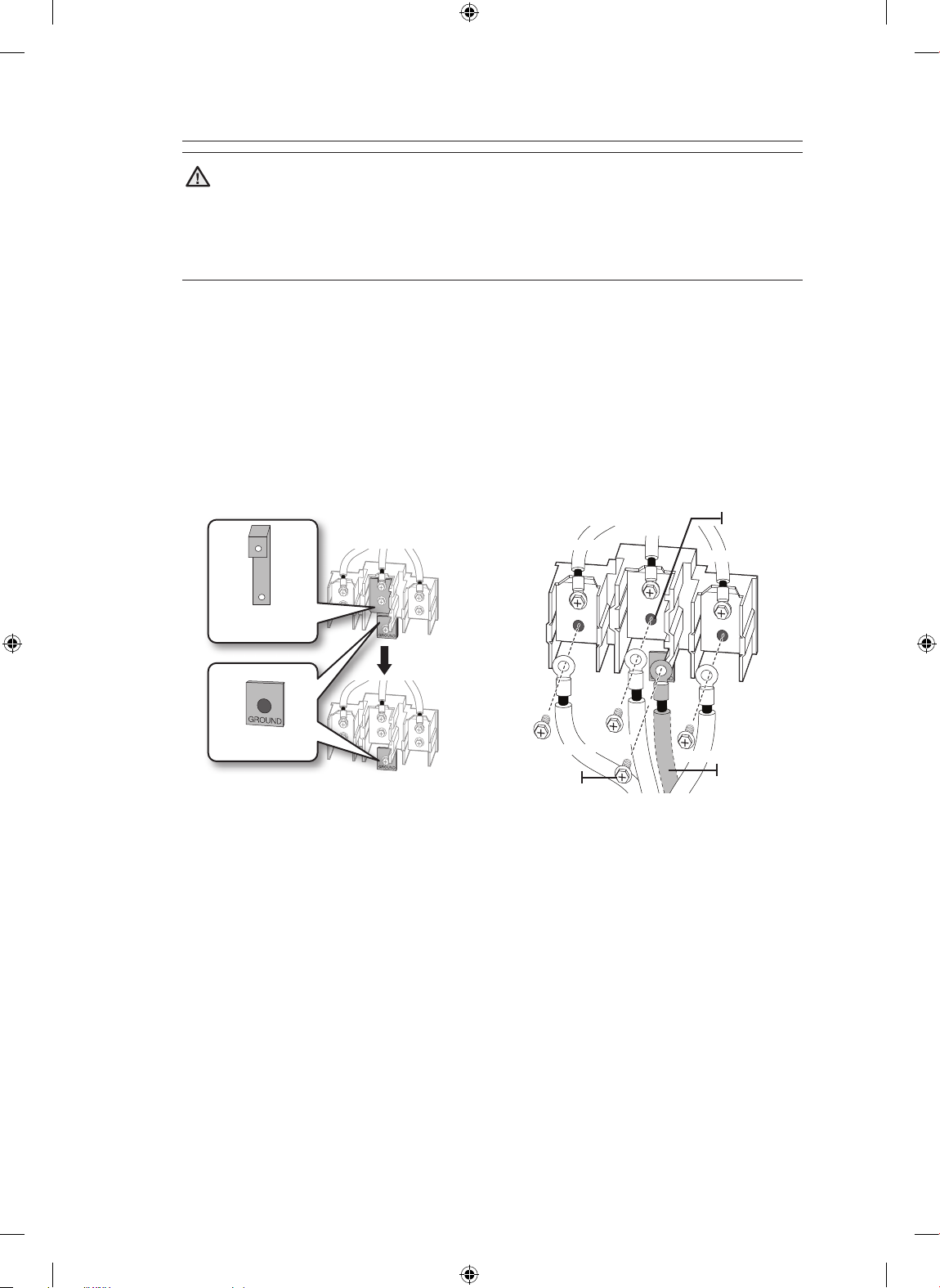
Instalación de un cable de alimentación de 4 conductores
ADVERTENCIA
ADVERTENCIA El conductor neutro del circuito de alimentación debe conectarse a
la terminal neutra ubicada en la parte central inferior del cuerpo de terminales. Los chicotes de cable
que portan corriente deben conectarse a las terminales inferior izquierda e inferior derecha del cuerpo
de terminales. El cuarto chicote de conexión a tierra debe conectarse al marco de la estufa con la
chapa y el tornillo de conexión a tierra.
1. Retire los tornillos de las tres terminales inferiores del cuerpo de terminales. Retire el tornillo y la
chapa de conexión a tierra y guárdelos.
2. Corte y descarte la cinta de conexión a tierra. No descarte ningún tornillo.
3. Introduzca el único tornillo de tierra en la terminal de aro de tierra del cable de alimentación,
también a través de la chapa de conexión a tierra y dentro del marco de la estufa.
4. Introduzca los 3 tornillos terminales (retirados anteriormente) a través de cada aro terminal del
cable de alimentación y dentro de las terminales inferiores del cuerpo de terminales. Asegúrese
de que el conductor central (blanco/neutro) sea conectado a la posición central inferior del cuerpo
de terminales. Ajuste los tornillos al cuerpo de terminales en forma segura.
5. Vaya al paso 5 en la página 10 y continúe con la instalación.
Cinta de conexión
a tierra
Chapa de conexión
a tierra
Negro
Negro
Tornillo de
conexión a
tierra
Blanco
Blanco
Terminal
neutra
Rojo
Rojo
Conductor a
tierra (Verde)
Español - 8
Install_30_Electric_Range_USA_DG68-00108G-04_MES.indd 8 3/30/2016 10:21:03 PM
Page 21
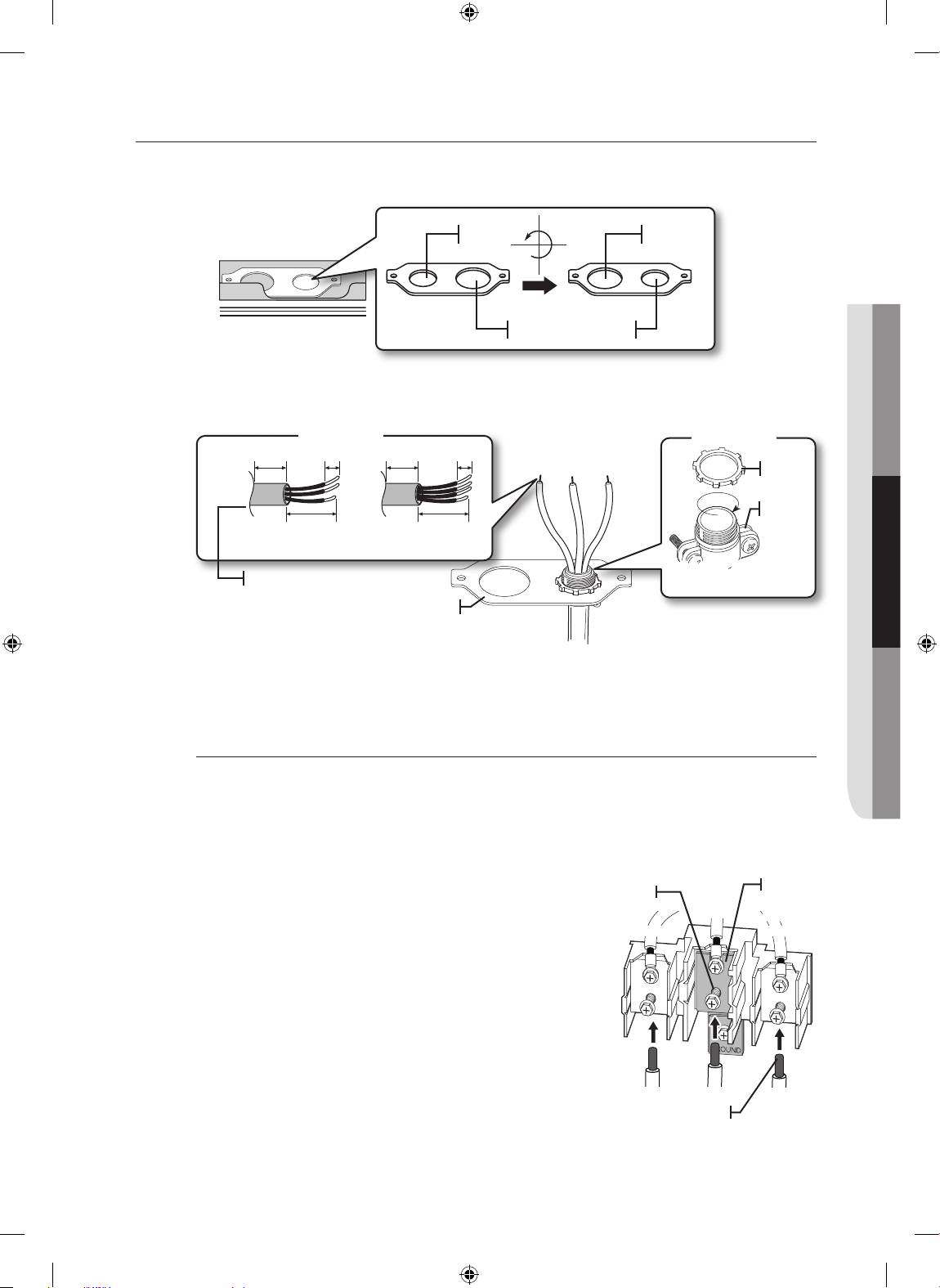
PASO 4. INSTALACIÓN DEL CONDUCTO
02 CONEXIÓN A LA CORRIENTE ELÉCTRICA
Retire la placa de conexión del conducto de la parte trasera del cuerpo del cajón y rótela como se muestra abajo.
1
Se debe utilizar el orificio de conducto (1
1. Prepare el cable de conducto que se muestra en la Figura 1.
2. Instale el cable de conducto como se muestra en la Figura 2.
/8").
1
1
/8" 13/8"
1
1
/8"13/8"
Figura 2
1"
Figura 1
3
/8" 1"
3
/8"
Aro
1
3
/2"
1
3
/2"
Cuerpo
3 conductores 4 conductores
Superficie de salida
Sujetador de cable con
amortiguador de esfuerzo
Placa de conducción del conducto
En el caso de instalaciones de conducto, introduzca el sujetador de cables con amortiguador de esfuerzo (no incluido) en
el orificio del conducto (1
1
/8"). Luego pase el cable de conducto a través del cuerpo del sujetador-amortiguador y ajuste el
tornillo. Reinstale la placa.
Instalación de un conducto de tres conductores
• Se puede utilizar alambre de construcción de aluminio pero debe estar graduado y aprobado para los amperajes
y voltajes correctos para hacer la conexión. Conecte los conductores de acuerdo con el Paso 4, dependiendo del
número de conductores.
• Los conductores utilizados, la ubicación y el encapsulamiento de uniones, etc. deben cumplir con las buenas prácticas
de cableado y los códigos locales.
1. Afloje los tornillos de las 3 terminales inferiores del cuerpo de
terminales.
2. Introduzca la punta desnuda del conductor central (blanco/
neutro) a través de la abertura en la parte central inferior del
cuerpo de terminales. En ciertos modelos, será necesario
introducir el conductor a través de la abertura de la cinta de
conexión a tierra y luego dentro de la abertura en la parte
central inferior del cuerpo de terminales.
3. Introduzca las puntas desnudas de los dos conductores
laterales en las aberturas inferior izquierda e inferior derecha del
cuerpo de terminales.
4.
Ajuste los tornillos hasta que los conductores queden firmemente
anclados (35 a 50 pulgadas-libras de torque). No ajuste los
tornillos en exceso porque esto podría dañar los conductores.
5. Vaya al paso 5 en la página 10 y continúe con la instalación.
Terminal
neutra
Negro
Negro
Blanco
Blanco
Puntas de conductor
Cinta de
conexión
a tierra
Rojo
Rojo
Español - 9
Install_30_Electric_Range_USA_DG68-00108G-04_MES.indd 9 3/30/2016 10:21:03 PM
Page 22
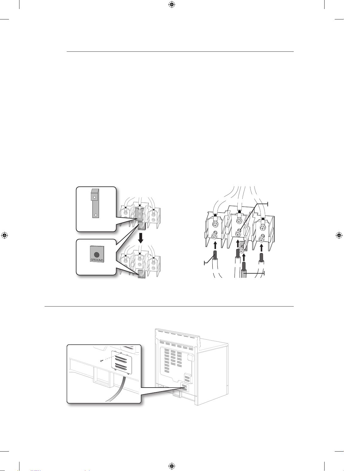
Instalación de un conducto de cuatro conductores
• Se puede utilizar alambre de construcción de aluminio pero debe estar graduado y aprobado para
los amperajes y voltajes correctos para hacer la conexión. Conecte los conductores de acuerdo con
este Paso 4, dependiendo del número de conductores.
• Los conductores utilizados, la ubicación y el encapsulamiento de uniones, etc. deben cumplir con
las buenas prácticas de cableado y los códigos locales.
1. Afloje los tornillos de las 3 terminales inferiores del cuerpo de terminales. Retire el tornillo y la
chapa de conexión a tierra y guárdelos.
2. Corte y descarte la cinta de conexión a tierra. No descarte ningún tornillo.
3. Inserte la punta desnuda del conductor de tierra entre el marco de la estufa y la chapa de
conexión a tierra (retirados anteriormente) y fíjelo en su lugar con el tornillo de conexión a tierra.
4. Introduzca la punta desnuda del conductor (blanco/neutro) a través de la abertura en la parte
central inferior del cuerpo de terminales.
5. Introduzca las puntas desnudas de los dos conductores laterales en las aberturas inferior
izquierda e inferior derecha del cuerpo de terminales.
6. Ajuste los tornillos hasta que los conductores queden firmemente anclados (35 a 50 pulgadaslibras de torque). No ajuste los tornillos en exceso porque esto podría dañar los conductores.
7. Vaya al paso 5 y continúe con la instalación.
Cinta de conexión
a tierra
Chapa de conexión
a tierra
Puntas de
conductor
Negro
PASO 5. RECOLOCAR LA CUBIERTA DE ACCESO
Recoloque la cubierta de acceso en la parte trasera de la estufa. Para recolocar la cubierta de los
conductores, inserte las dos pestañas en las cavidades ubicadas debajo de la abertura y ajuste el tornillo.
Negro
Blanco
Blanco
Rojo
Rojo
Terminal
neutra
Conductor a
tierra (Verde)
Español - 10
Install_30_Electric_Range_USA_DG68-00108G-04_MES.indd 10 3/30/2016 10:21:04 PM
Page 23
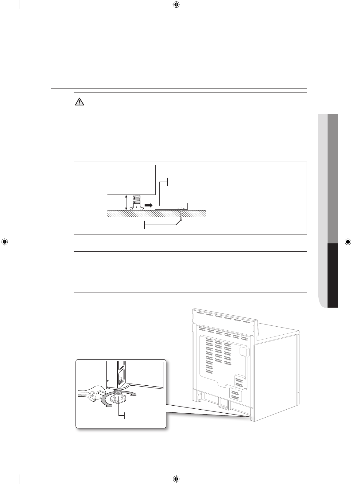
instalación de la estufa
03 INSTALACIÓN DE LA ESTUFA
INSTALACIÓN DEL DISPOSITIVO ANTI INCLINACIÓN
ADVERTENCIA
ADVERTENCIA Para reducir el riesgo de inclinaciones o vuelcos, el electrodoméstico
debe quedar correctamente asegurado mediante la instalación del Dispositivo Anti Inclinación que
viene empacado con su electrodoméstico.
• Remítase a las instrucciones de instalación incluidas con la ménsula.
• Salvo que se encuentre correctamente instalada, la estufa se podría inclinar o volcar si alguna
persona pisase la puerta o se sentara sobre ella. Podrían ocurrir lesiones causadas por el mismo
peso de la estufa o por derrames de líquidos calientes.
Ménsula anti
inclinación
*aproximadamente
21/32 pulgadas (16.5 mm)
El tornillo debe introducirse
en madera o concreto.
*NOTA: Para instalar la ménsula Anti
Inclinación libere la pata niveladora.
Se requiere una distancia mínima de
21/32 pulgadas (16.5 mm) entre la
parte inferior de la estufa y el piso de la
cocina.
1. Ubique la ménsula en la posición adecuada utilizando la plantilla
La ménsula anti inclinación se encuentra empacada junto con una plantilla. Las instrucciones incluyen
la información necesaria para completar la instalación. Lea y siga las instrucciones en la hoja (plantilla)
para la instalación de la estufa.
2. Nivelación de la estufa
Nivele la estufa ajustando las patas niveladoras con una llave.
Levantar la estufa
Bajar la estufa
Pata
niveladora
Español - 11
Install_30_Electric_Range_USA_DG68-00108G-04_MES.indd 11 3/30/2016 10:21:04 PM
Page 24

3. Controle sus ajustes
Utilice un nivel de burbuja de aire para controlar los ajustes. Coloque el nivel en diagonal sobre la
parrilla del horno o la superficie de cocción y controle que esté nivelado en todas direcciones.
FINALIZACIÓN DE LA INSTALACIÓN
• Mueva la estufa lo suficientemente cerca de su lugar como para enchufar en el tomacorriente.
• Deslice la estufa a su posición, asegurándose de que la pata trasera izquierda (o trasera derecha) se
deslice por debajo de la ménsula anti inclinación. Cuando se encuentre bien instalada, la distancia
entre la estufa y la pared de atrás será de 0".
• Con cuidado, incline la estufa hacia adelante para verificar que la ménsula Anti Inclinación engancha
al puntal trasero e imposibilita el vuelco.
• Encienda la corriente eléctrica. Controle el funcionamiento correcto de la estufa tal como se
describe en el manual del usuario.
1. Controle en la dirección 1.
2. Controle en la dirección 2.
Si el nivel de burbuja muestra alguna inclinación en
la parrilla o la superficie de cocción, ajuste las patas
de nivelación con una llave.
Español - 12
Ménsula anti inclinación
Pata niveladora
DG68-00108G-04
Install_30_Electric_Range_USA_DG68-00108G-04_MES.indd 12 3/30/2016 10:21:05 PM
 Loading...