

Page 1
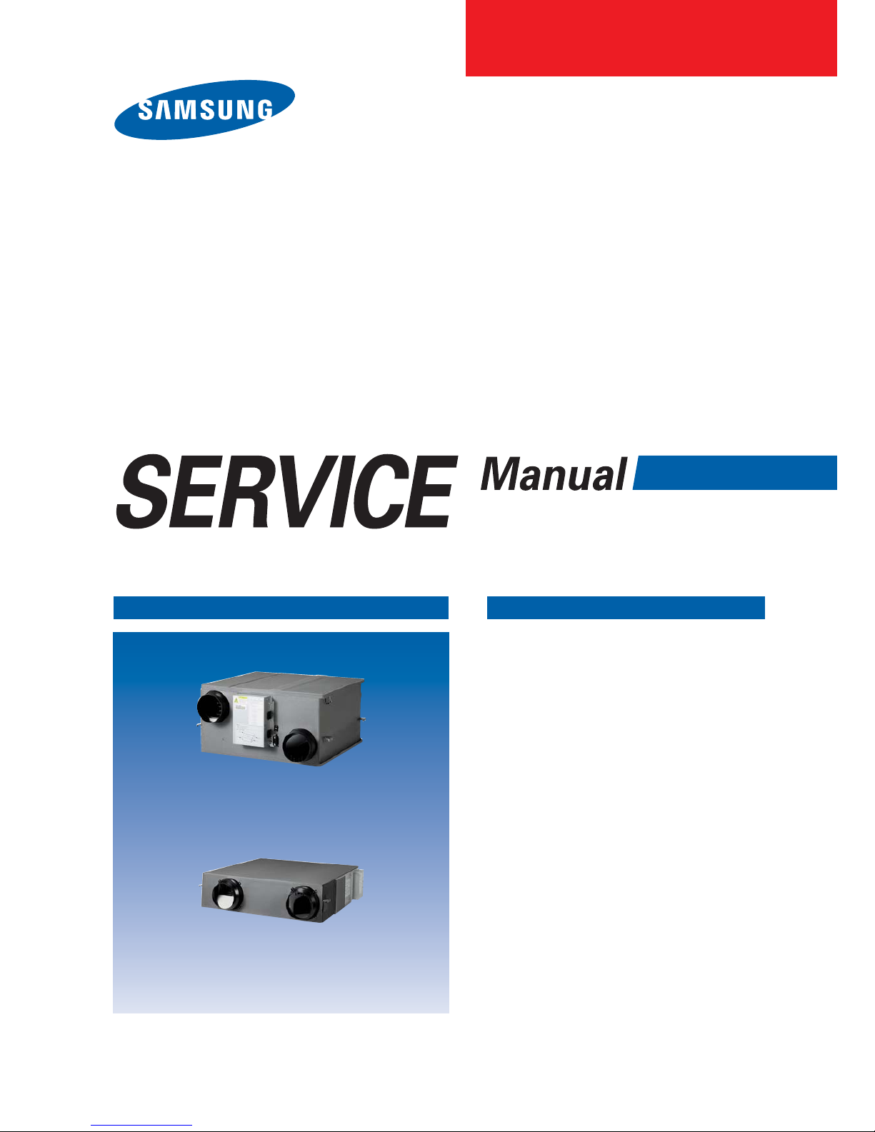
ERV(Energy Recovery Ventilator)
Basic : RHF025EE/035EE/050EE/080EE/100EE
Model
: AN026JSKLKN
AN035JSKLKN
AN050JSKLKN
AN080JSKLKN
AN100JSKLKN
Model Code : AN026JSKLKN/EU
AN035JSKLKN/EU
AN050JSKLKN/EU
AN080JSKLKN/EU
AN100JSKLKN/EU
ERV(Energy Recovery Ventilator) CONTENTS
1. Precautions
2. Product Specifications
3. Alignment and Adjustments
4. Disassembly and Reassembly
5. Wiring Diagram
6. Circuit Descriptions
7. PCB Diagram
8. Operating Instructions
9. Troubleshooting
10. Reference Sheet
AN026JSKLKN
AN035JSKLKN, AN050JSKLKN
AN080JSKLKN, AN100JSKLKN
Page 2

Samsung Electronics 1
Contents
1. Precautions
·········································································································································
1-1
1-1 Installing the Ventilator
····················································································································
1-1
1-2 Power supply and circuit breaker
···································································································
1-2
1-3 During operation
·······························································································································
1-2
1-4 Others
··················································································································································
1-3
2. Product Specifications
················································································································
2-1
2-1 The Feature of Product
·····················································································································
2-1
2-2 Product Specifications
······················································································································
2-2
2-3 Option Specifications
························································································································
2-5
3. Alignment and Adjustments
··································································································
3-1
3-1 Error Mode and Check Method
······································································································
3-1
3-2 Option Switch & Key Function Address
························································································
3-2
4. Disassembly and Reassembly
·······························································································
4-1
4-1 AN026JSKLKN
·····································································································································
4-2
4-2 AN035JSKLKN/AN050JSKLKN/AN080JSKLKN/AN100JSKLKN
··················································
4-16
5. Wiring Diagram
·······························································································································
5-1
6. Circuit Descriptions
·······················································································································
6-1
6-1 PCB Circuit Descriptions
···················································································································
6-1
7. PCB Diagram
······································································································································
7-1
8. Operating Instructions
···············································································································
8-1
8-1 Name of Each Part
·····························································································································
8-1
8-2 Using installation/service mode of ERV wired remote controller
············································
8-5
9. Troubleshooting
·····························································································································
9-1
9-1 Items to be checked first
··················································································································
9-1
9-2 When Ventilator stops operation
····································································································
9-1
9-3 Errors and Solutions
··························································································································
9-2
9-4 Fault Diagnosis by Symptom
··········································································································
9-3
Page 3

2 Samsung Electronics
Contents
10. Reference Sheet
·······························································································································
10-1
10-1 Ventilator Operation Priniple
········································································································
10-1
10-2 Index for Model Name
···················································································································
10-2
10-3 Cleaning the Dust Filter
·················································································································
10-3
10-4 Cleaning the Heat Exchange Element
·························································································
10-5
10-5 Q & A for Non-trouble
····················································································································
10-7
Page 4

Samsung Electronics 1-1
1. Precautions
1-1 Installing the Ventilator
O Consult a dealer or a qualified installer.
– Incorrect installation of the unit could cause injury due to fire, electric shock and water leakage or from the unit falling.
O Hang down a blockage for bird in front of outdoor air suction duct.
– If something such as bird’s nest blocks the air suction duct, it may result in oxygen shortage in indoors.
O Check if the voltage and the frequency of the main power supply are required for the unit to be installed.
– Defective voltage and power supply could cause injury due to fire or from the unit falling.
O Ground the unit. Do not connect the ground to a gas pipe, water pipe, lighting rod or telephone grounding.
– Defective grounding could cause electric shock.
O Install the unit in a place where it is strong enough to hold the product weight.
– When installed in place where it is not strong enough to withhold the product weight, the unit may fall and cause injury.
O The electric work must be done by service agent or similarly qualified person according to national wiring regulations and
use only rated cable.
– If the capacity of the electric work is not properly completed, unit falling, electric shock or fire may occur.
O Do not attempt to repair, move, modify or reinstall the unit on your own.
– Make sure that these installations are carried out by qualified personnel to avoid electric shock or fire.
O Perform the installation securely referring to the installation manual.
– Incomplete installation could cause personal injury due to fire, electric shock or the unit falling.
O Do not install the product in a place where it is or might be exposed to inflammable gas leakage.
– When the unit is exposed to inflammable gas leakage, it could catch fire or cause explosion.
O Make sure to use the part provided or specified parts for the installation work.
– The use of defective parts could cause fire or electric shock.
O Do not install the product in the place where generates toxic gas from machinery or chemical factory such as alkali
solution, organic solvent, or paints.
– It may cause fire or gas poisoning.
O Do not install the product in a place where it might be exposed to petroleum, steam, or sulphuric acid.
– When the unit is exposed to petroleum, steam, or sulphuric acid, unit falling or malfunction may take place.
O Make sure the air intake is located far from an exhaust port of a burner.
– It may cause indoor oxygen shortage.
O Install the product inside heat insulation over the ceiling not to be contacted with the outside air.
– If the product is installed out of the insulation, it may result in electric shock or malfunction due to moisture generated in the
product.
O Do not install the product in humid place such as bathroom.
– It may cause electric shock or malfunction.
Page 5

1-2 Samsung Electronics
1-2 Power supply and circuit breaker
O Turn off the sub power supply when you don’t use the product for a long period.
– If not, it may cause power consumption or fire.
O Install a ground leakage breaker depending on the installation place.
– If not, it may cause electric shock.
O Ensure that the national safety code requirements have been followed for the main supply circuit. Ensure that a properly
sized and connected ground wire is in place.
– Inappropriate wire may cause overheating of fire.
O Turn the power off before repairing the product.
– If not, it may cause electric shock.
O Do not install the electric wire to get tension.
- The electric wire may disconnect and cause fire.
O Do not utilize ERV wired remote control with wet hands.
– It may cause electric shock.
O If the power cable is damaged, replace it by the manufacturer or qualified personnel to avoid the risk.
1-3 During operation
O Open windows for air circulation when a burner or other product leaks inflammable gas.
– If not, it may cause fire or explosion.
O Make sure to keep winds from the product away from a burner.
– It may cause incomplete combustion.
O Do not utilize the ventilator to preserve machinery, foods, animals, plants or cosmetic products.
– It may cause damage to the machinery, foods, animals, plants or cosmetic products.
O Do not spray insecticide or other inflammable materials on the product.
– It may cause unit falling or fire.
O Make sure to keep the product away from water.
– The product can cause electric shock or fire when it contacts water.
O Do not put the product under a great pressure or reinstall the unit on your own.
– It may cause fire or malfunction.
O Do not utilize the product for air exchange when an open type burner is used.
– Separate measures for air exchange must be prepared when a gas or oil stove is used.
O Ensure that indoor air should not flow into the outdoor air suction duct of the product.
– If not, indoor air may be contaminated to have a bad influence on heath of people.
O Stop operating the product as soon as any error is found.
– Stop operating and turn off the unit when it smells burning or any error in operation is found. Contact a dealer or a qualified
installer. If continue operation of the unit, electric shock, fire or unit falling may occur.
Page 6

Samsung Electronics 1-3
1-4 Others
O The dust filter of the product must be inserted before operation. Dust filter is required to be cleaned about two times a
year regularly.
– If not, the product function may fall.
O Make sure wear gloves when cleaning dust filter or heat exchange element.
– If not, it may cause injury.
O Make sure air fan stops rotating before cleaning and other treatment.
– If not, it may cause electric shock or injury.
O Do not utilize steel scrubber or chemicals such as benzene or thinner.
– It may cause discoloration or unit falling.
O Do not expose animals or plants to the winds from the unit for a long period of time.
– It may damage animals or plants.
O Do not put hands or sticks into the air suction duct or air outlet of the product.
– It may cause injury as ventilator fan is rotating fast.
O Do not attempt to modify or reinstall the unit on your own.
– It may cause unit falling, electric shock or fire. Consult a dealer or a qualified installer.
Page 7
Samsung Electronics 2-1
2. Product Specifications
2-1 The Feature of Product
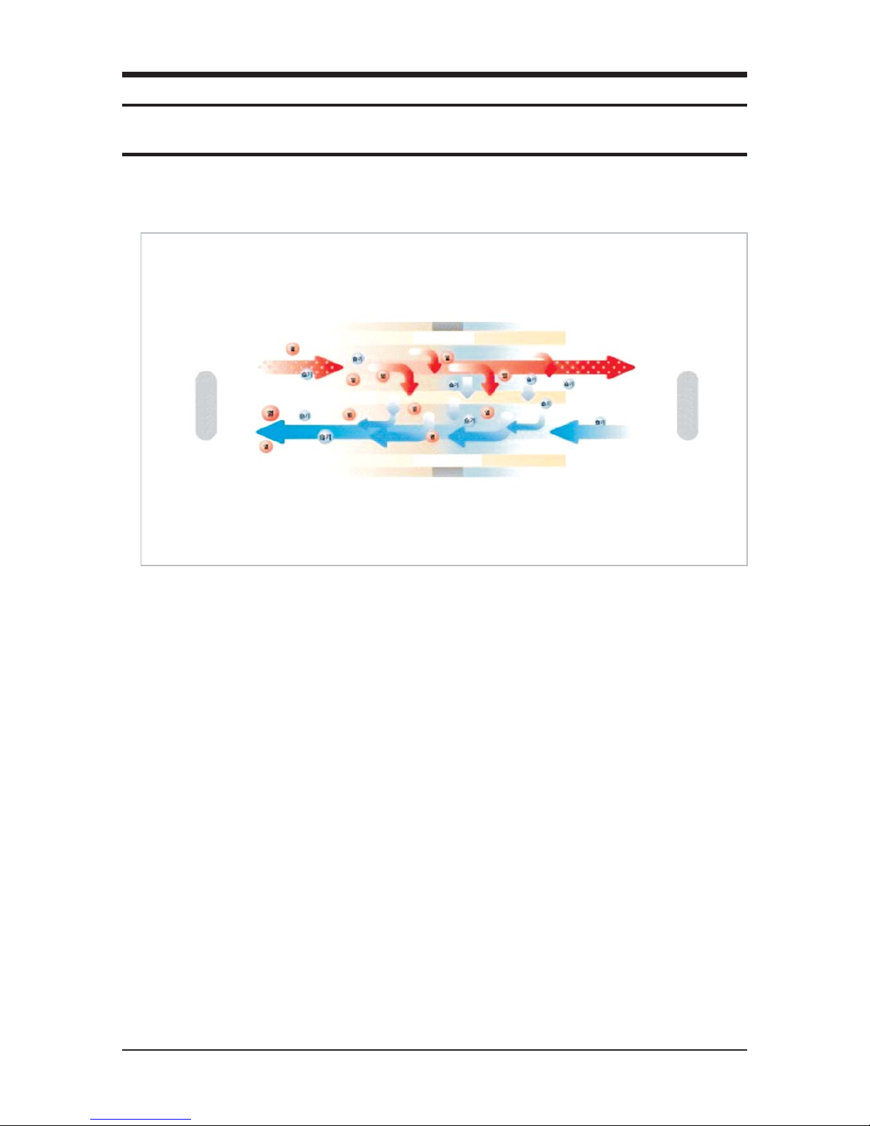
Q Energy Recovery Ventilation
The product helps save energy and drive down operation costs of heaters and coolers by recycling thermal energy (energy load)
efficiently.
Q Air Volume Control
Air volume control minimizes energy loss and cuts down on energy usage, even when duct resistance is low at the time of installation.
Q Automatic Operation
Operation mode and air volume are controlled automatically by sensing indoor and outdoor air conditions.
Q Exchange Mode
Heat-EX mode is utilized in summer and winter while usual ventilation mode is used in spring and autumn.
– Heat-Ex Mode : Energy loss is minimized by recycling energy exhausted when indoor heating and cooling.
– By-Pass Mode : The ventilation method is used when temperature gap of indoor and outdoor is not big. Outdoor air flows into
indoor.
Q High Sensibility Sensor (Option)
An optimal air condition is maintained through Carbon Dioxide (CO2) sensor and temperature sensor.
Q Humidity Control
Fresh air conditions are guaranteed by recovering moisture in winter while exhausting it in summer.
Q Operation at Cold Area
Optimized automatic ventilation operation is conducted to prevent condensation and air volume reduction.
Q Low Noise and Low Power
With highly efficient motor and optimized system design, operation noise and electric consumption is minimized.
Indoor
Outdoor
Contaminated air with
high temperature and humidity
Heat Exchange Element
Heat Exchange Element
Heat Exchange Element
Fresh air with Low Temperature
and Humidity
Heat Exchanged Fresh Air
Cold and Contaminated Air
Page 8

2-2 Samsung Electronics
2-2 Product Specifications
Power Source 220 - 240 V~, 50 / 60 Hz
Ventilation Mode Heat-Ex Ventilation By-Pass Ventilation
The Level of the Air Volume Turbo High Low Turbo High Low
Power Supply(W) 115 80 45 115 80 45
Air Volume(m³/h) 260 250 180 250 250 180
External Static Pressure(Pa) 100 65 55 110 65 55
Temperature Exchange
Efficiency(%)
Cooling 70 70 74 - - -
Heating 70 70 74 - - -
Enthalpy Exchange
Efficiency(%)
Cooling 50 50 55 - - -
Heating 70 70 76 - - -
Size(widthxheightxdepth)(mm) 600 x 350 x 660
Weight(kg) 28.5
Duct Size(mm) 150
Trial Operation Conditions
1. Air Volume/ External Static Pressure, Comply with KS Heat Exhaust Ventilation System Standards(KS B6879).
2. Heat Exchange/Temperature Exchange Efficiency, Comply with regulations to promote high efficiency energy devices,
[Cooling], Indoor(24˚C DB/17˚C WB), Outdoor(35˚C DB/24˚C WB)
[Heating], Indoor(22˚C DB/13.9˚C WB), Outdoor(2˚C DB/0.44˚C WB)
QAN026JSKLKN
Power Source 220 - 240 V~, 50 / 60 Hz
Ventilation Mode Heat-Ex Ventilation By-Pass Ventilation
The Level of the Air Volume Turbo High Low Turbo High Low
Power Supply(W) 115 80 50 115 80 50
Air Volume(m³/h) 350 350 260 350 350 260
External Static Pressure(Pa) 155 100 85 155 100 85
Temperature Exchange
Efficiency(%)
Cooling 70 70 74 - - -
Heating 70 70 74 - - -
Enthalpy Exchange
Efficiency(%)
Cooling 50 50 55 - - -
Heating 70 70 76 - - -
Size(widthxheightxdepth)(mm) 1,012 X 270 X 1,000
Weight(kg) 42.5
Duct Size(mm) 200
Trial Operation Conditions
1. Air Volume/ External Static Pressure, Comply with KS Heat Exhaust Ventilation System Standards(KS B6879).
2. Heat Exchange/Temperature Exchange Efficiency, Comply with regulations to promote high efficiency energy devices,
[Cooling], Indoor(24˚C DB/17˚C WB), Outdoor(35˚C DB/24˚C WB)
[Heating], Indoor(22˚C DB/13.9˚C WB), Outdoor(2˚C DB/0.44˚C WB)
QAN035JSKLKN
Page 9
Samsung Electronics 2-3
Product Specifications(cont.)
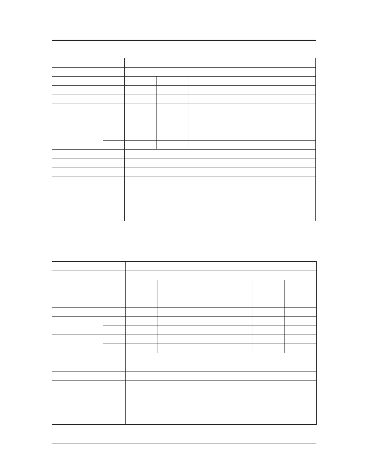
Power Source 220 - 240 V~, 50 / 60 Hz
Ventilation Mode Heat-Ex Ventilation By-Pass Ventilation
The Level of the Air Volume Turbo High Low Turbo High Low
Power Supply(W) 175 120 65 175 120 65
Air Volume(m³/h) 500 500 360 500 500 360
External Static Pressure(Pa) 165 100 85 165 100 85
Temperature Exchange
Efficiency(%)
Cooling 70 70 74 - - -
Heating 70 70 74 - - -
Enthalpy Exchange
Efficiency(%)
Cooling 50 50 55 - - -
Heating 70 70 76 - - -
Size(widthxheightxdepth)(mm) 1,012 X 270 X 1,000
Weight(kg) 42.5
Duct Size(mm) 200
Trial Operation Conditions
1. Air Volume/ External Static Pressure, Comply with KS Heat Exhaust Ventilation System Standards(KS B6879).
2. Heat Exchange/Temperature Exchange Efficiency, Comply with regulations to promote high efficiency energy devices,
[Cooling], Indoor(24˚C DB/17˚C WB), Outdoor(35˚C DB/24˚C WB)
[Heating], Indoor(22˚C DB/13.9˚C WB), Outdoor(2˚C DB/0.44˚C WB)
QAN050JSKLKN
Power Source 220 - 240 V~, 50 / 60 Hz
Ventilation Mode Heat-Ex Ventilation By-Pass Ventilation
The Level of the Air Volume Turbo High Low Turbo High Low
Power Supply(W) 330 230 125 330 230 125
Air Volume(m³/h) 800 800 560 800 800 560
External Static Pressure(Pa) 155 90 80 155 90 80
Temperature Exchange
Efficiency(%)
Cooling 70 70 74 - - -
Heating 70 70 74 - - -
Enthalpy Exchange
Efficiency(%)
Cooling 50 50 55 - - -
Heating 70 70 76 - - -
Size(widthxheightxdepth)(mm) 1,220 × 340 × 1,135
Weight(kg) 67
Duct Size(mm) 250
Trial Operation Conditions
1. Air Volume/ External Static Pressure, Comply with KS Heat Exhaust Ventilation System Standards(KS B6879).
2. Heat Exchange/Temperature Exchange Efficiency, Comply with regulations to promote high efficiency energy devices,
[Cooling], Indoor(24˚C DB/17˚C WB), Outdoor(35˚C DB/24˚C WB)
[Heating], Indoor(22˚C DB/13.9˚C WB), Outdoor(2˚C DB/0.44˚C WB)
QAN080JSKLKN
Page 10
2-4 Samsung Electronics
Product Specifications(cont.)
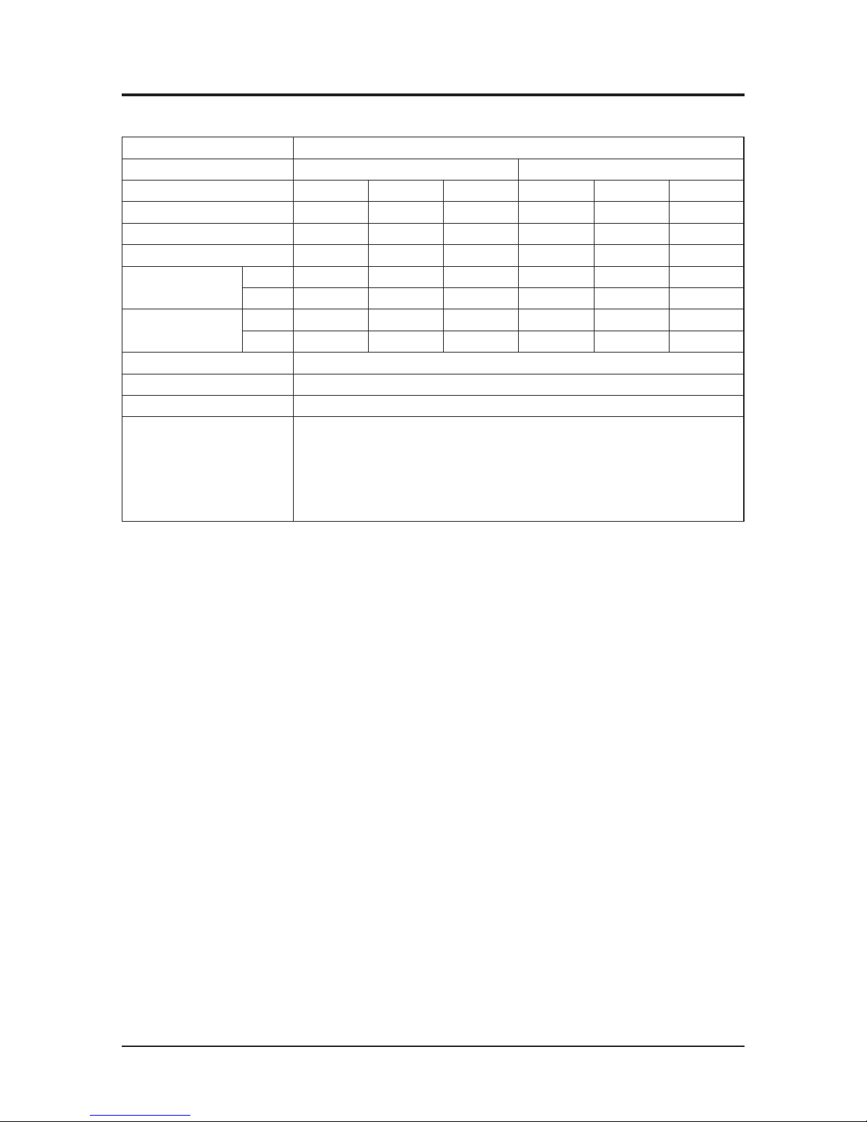
QAN100JSKLKN
Power Source 220 - 240 V~, 50 / 60 Hz
Ventilation Mode Heat-Ex Ventilation By-Pass Ventilation
The Level of the Air Volume Turbo High Low Turbo High Low
Power Supply(W) 450 280 155 450 280 155
Air Volume(m³/h) 1000 1000 690 1000 1000 690
External Static Pressure(Pa) 155 90 75 155 90 75
Temperature Exchange
Efficiency(%)
Cooling 70 70 74 - - -
Heating 70 70 74 - - -
Enthalpy Exchange
Efficiency(%)
Cooling 50 50 55 - - -
Heating 70 70 76 - - -
Size(widthxheightxdepth)(mm) 1220 × 340 × 1135
Weight(kg) 67
Duct Size(mm) 250
Trial Operation Conditions
1. Air Volume/ External Static Pressure, Comply with KS Heat Exhaust Ventilation System Standards(KS B6879).
2. Heat Exchange/Temperature Exchange Efficiency, Comply with regulations to promote high efficiency energy devices,
[Cooling], Indoor(24˚C DB/17˚C WB), Outdoor(35˚C DB/24˚C WB)
[Heating], Indoor(22˚C DB/13.9˚C WB), Outdoor(2˚C DB/0.44˚C WB)
Page 11
Samsung Electronics 2-5
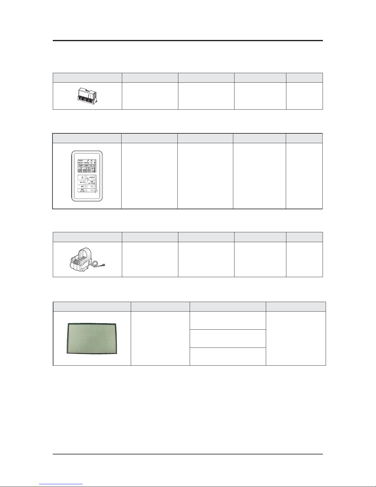
2-3 Option Specifications
2-3-1. Accessories
Item Descriptions Code-No Q'TY
Remark
ASS'Y CO2 SENSOR DB95-00740A 1
Separate Sale
Ŷ MOS-C1 (CO2 Sensor)
Item Descriptions Code-No Q'TY Remark
ASS'Y-SPi DEIVICE
OPTION KIT
DB97-09494B 1 Separate Sale
Ŷ
MSD-EAN1(Assy-SPI Device Option Kit )
Item Descriptions Code-No Q'TY Remark
ASS'Y ERV REMOCON DB93-14406C 1 Separate Sale
Ŷ MWR-VH12N (Wired Remote Controller)
2-3-2. Filter Specifications
Item Descriptions Code-No Remark
Duts Filter
DB63-01665A
(AN026JSKLKN)
Basic/Cleaning
Impossibility of Water Washing
DB63-01665F
(AN035JSKLKN, AN050JSKLKN)
DB63-01665G
(AN080JSKLKN, AN100JSKLKN)
Page 12
Samsung Electronics 3-1
3. Alignment and Adjustments
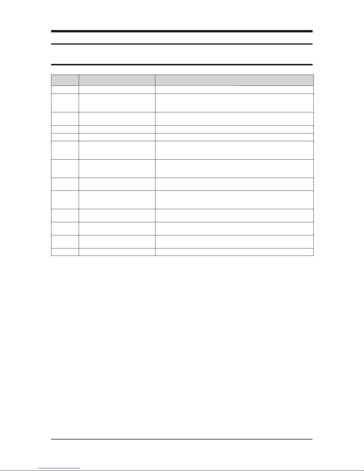
3-1 Error Mode and Check Method
Error No Error Mode Measures
E108 Address setting duplication error · Check the overlapping MAIN address within same repeater.
E121
Indoor temperature sensor
error(SHORT/OPEN)
· Check connector disconnection of CN41 & connection conditions.
Check a voltage of both ends CN41 PIN#1,2 (10 Ꮒ at 25 degrees)
A Check of Indoor temperature is possible when KEY2 switch is entered 3 times.
E139
CO
sensor error(SHORT/OPEN)
· Check connector disconnection of
CO
sensor and connection conditions.
A Check of
CO
sensor value is possible when KEY2 switch is entered 5 times.
E162 Indoor EEPROM H/W error · Check connection conditions of EEPROM SUB PBA.
E163 Indoor option setting error · Need to reset option.
E183 Outdoor Humidity Sensor Error(ERV)
· Check connector disconnection of humidity sensor and connection conditions.
· A Check of outdoor humidity value is possible when KEY2 switch is entered 8 times.
Set operates normall regardless of error.
E198
Thermal fuse open error in power therminal block
· Check wire connection conditions of CN140 connector.
· Check conditions of wire connected power terminal block.
(occurrence of error at open)
E202
System down caused by communication error
· Check disconnection of communication wire.
E221
Outdoor temperature sensor
error(SHORT/OPEN)
· Check connector disconnection of CN41 and connection conditions.
· Check a voltage of both ends CN41 PIN#3,4 (10 Ꮒ at 25 degrees).
A Check of indoor temperature is possible when KEY2 switch is entered 4 times.
E490
Prohibition of operation under outside
& indoor temperature 0 degrees
· Set stop operates normally when indoor and outdoor temperature is under 0 degrees.
· Prohibition of operation for set protection.
E561 Supply air(SA) fan motor error
· Check connector disconnection of CN74 and connection conditions.
· A Check of supply air fan rpm is possible when KEY2 switch is entered twice.
E562 Exhaust air(EA) fan motor error
· Check connector disconnection of CN73 and connection conditions.
· A Check of exhaust air fan rpm is possible when KEY2 switch is entered once.
E654 Inside damper error · Check connector disconnection of CN72,CN52 and connection conditions.
Page 13
3-2 Samsung Electronics
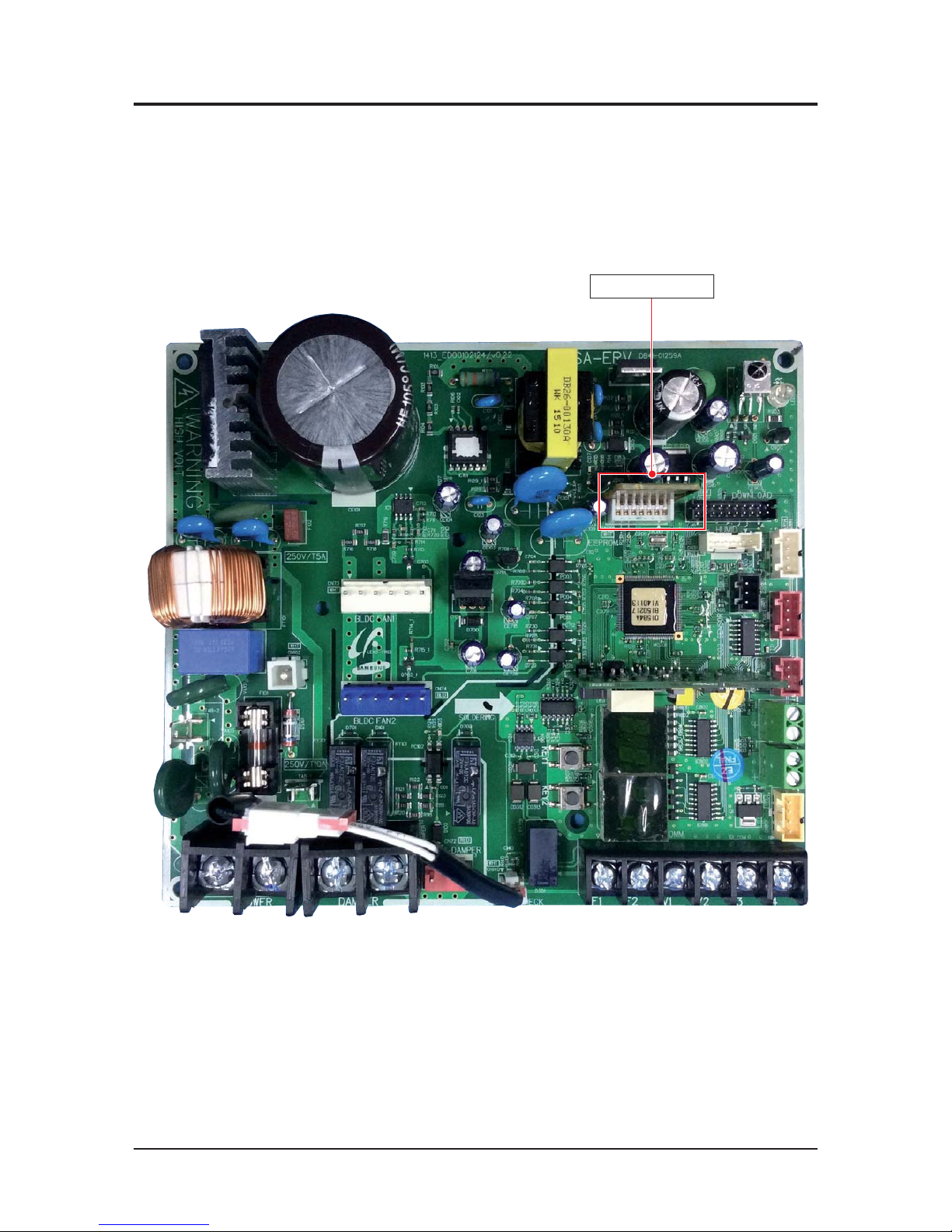
3-2 Option Switch & Key Function Address
م If you use a existing EEPROM after replace MAIN PBA, don't need to reset option.
SUB EEPROM PBA
Page 14
Samsung Electronics 3-3
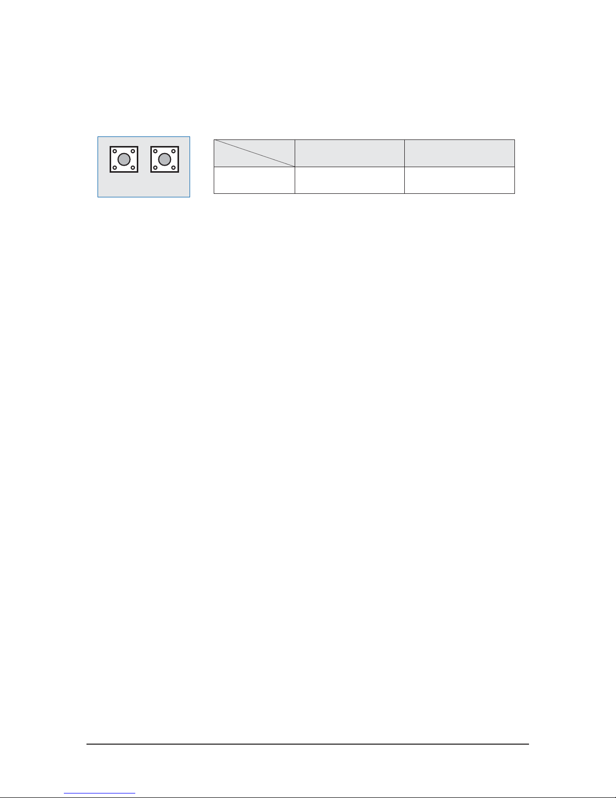
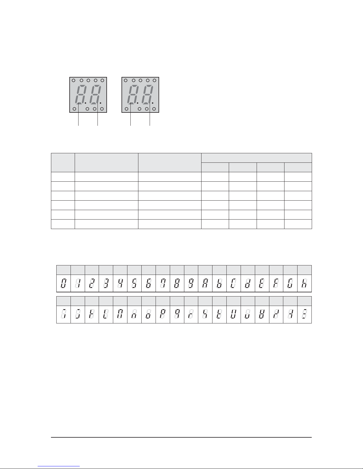
3-2-1 Operation KEY and Display
1. KEY Function
Ɣ
Trial Operation of Heat Exchange(KEY1) : The operation is to check whether the product operates properly after
the installation.
1) KEY 1 : Trial operation
Ɣ
Operation condition : Heat exchange/Turbo wind
Ɣ
Repeat on/off of trial operation whenever a key enters.
Ɣ
Trial operation is stopped 30 minutes later, it returns to DISPLAY Default state 30 minutes later.
2) KEY 2 : Data display
Ɣ
The marked contents is changed whenever you press KEY2 once.
Ɣ
Press the KEY2 switch for more than 3 seconds to reset.
Function
Input Time
KEY1 KEY2
1 time Trial Operation of Heat Exchange Data Display
KEY 1 KEY 2
Page 15
3-4 Samsung Electronics
0123456789ABCDEFGH
IJKLMNOPQRSTUVWXYZ
QDisplay
g
SEG1
af
G1
G2
bc e d
SEG2
g
SEG3
af
G1
G2
bc e d
SEG4
QNumbers and Alphabets on PCB Display
Press times Indication Example
Display
SEG1 SEG2 SEG3
SEG4
1 Exhaust Air FAN RPM 1,350RPM 1 1 3
5
2 Supply Air FAN RPM 950RPM 2 Turn Off 9
5
3 Indoor Temperature 25°C 3 Turn Off 2
5
4 Outdoor Temperature 30°C 4 Turn Off 3
0
5CO2 Density 1,220ppm 5 1 2
2
6 Installed Unit Number 3 unit 6 Turn Off Turn Off
3
Page 16
Samsung Electronics 4-1
4. Disassembly and Reassembly
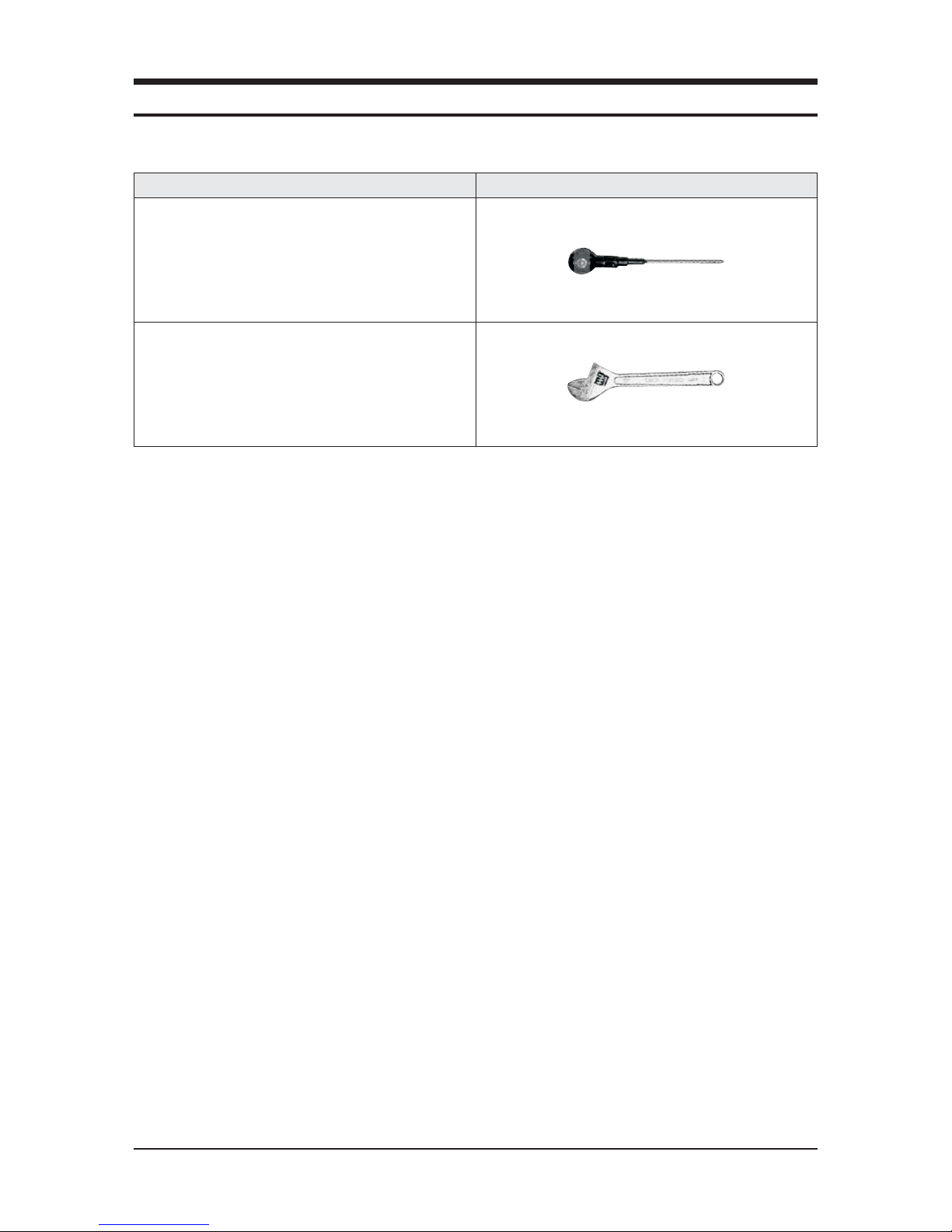
QNecessary Tools
Item Remark
+SCREW DRIVER
MONKEY SPANNER
Page 17
4-2 Samsung Electronics
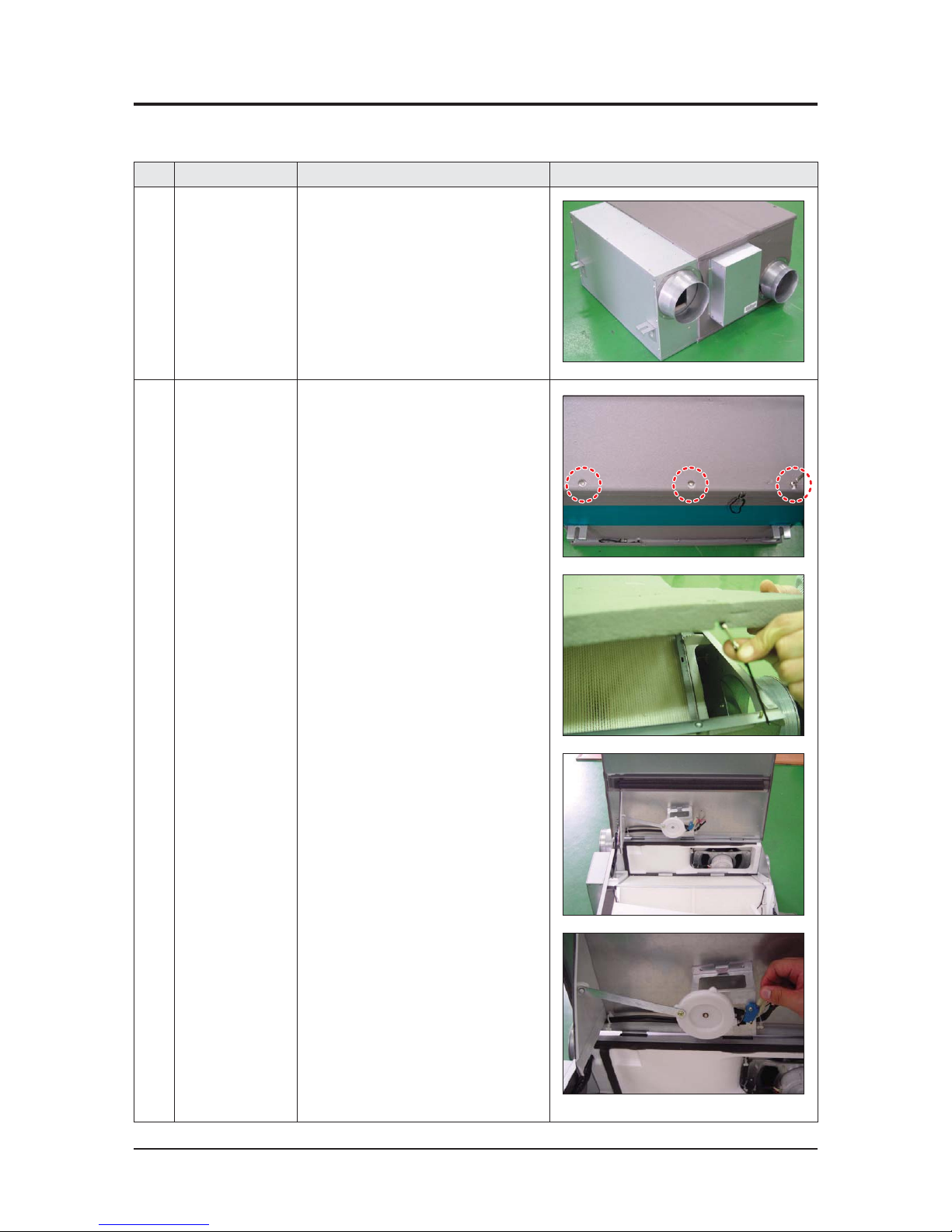
4-1 AN026JSKLKN
No Parts Procedure Remark
1 ERV
(Energy Recovery
Ventilator)
1) Stop the air conditioner operation and
shut off the main power.
2) Remove the unit from ceiling suspension.
(Disassembly is not required when Fan,
Motor, Element, Filter replacement or
cleaning.)
2
Ass’y Cabi
Cover Element
1) Remove the 3 bolts on Cover Element to
detach it.(Use +Screw Driver.)
2) Loosen the clips connected to the Cover.
3) Separate the connector connected to the
Damper by pulling out the connector body.
QDisassembly before Installation
Page 18
Samsung Electronics 4-3
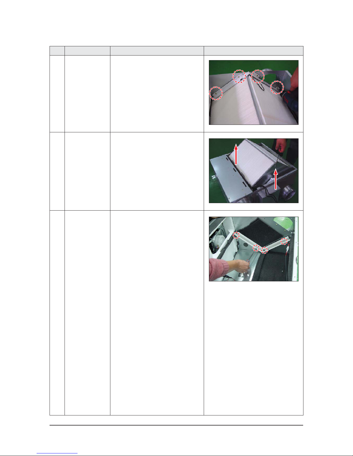
No Parts Procedure Remark
3 Bracket Body
Element, B
1) Remove the 4 bolts and separate Bracket
Body Element, B. (Use +Screw Driver.)
4 Ass’y Element 1) Pull up the 2 strings hanging out from the
2 ends of Element to detach the Element.
5 Bracket Body
Element, A
1) Remove the 4 bolts and separate Bracket
Body Element, A. (Use +Screw Driver.)
Page 19
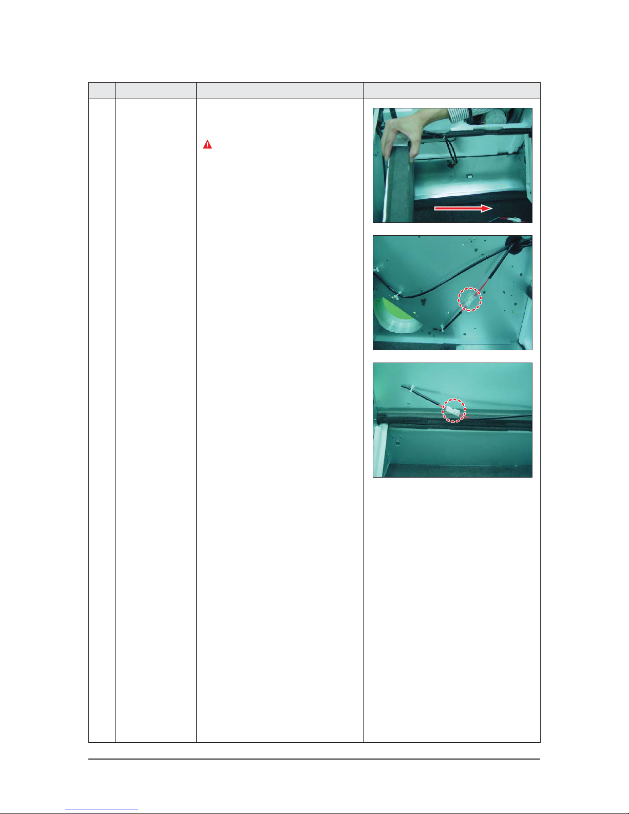
4-4 Samsung Electronics
No Parts Procedure Remark
6 Cushion Bypass 1) Slide Cushion Bypass to the direction seen
in the picture besides.
Take caution not to break down EPS
structure.
2) Find Wire connected to the temperature
sensor. Separate the 2 temperature sensor
connectors.
Page 20
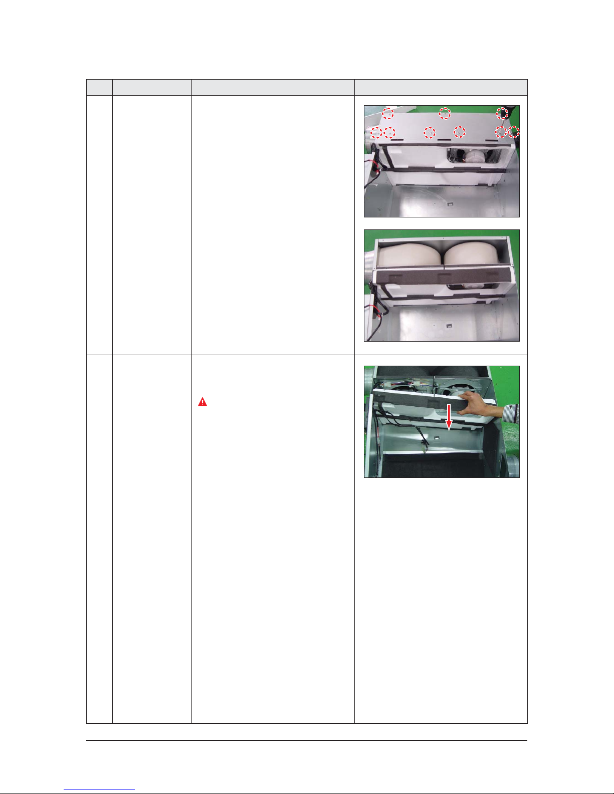
Samsung Electronics 4-5
No Parts Procedure Remark
7 Cabi Cover 1) Detach Cabi Cover by removing 9 bolts.
(Use +Screw Driver.)
8 Cushion Mid 1) Slide Cushion Mid to the direction seen in
the picture besides.
Take caution not to break down EPS
structure.
Page 21
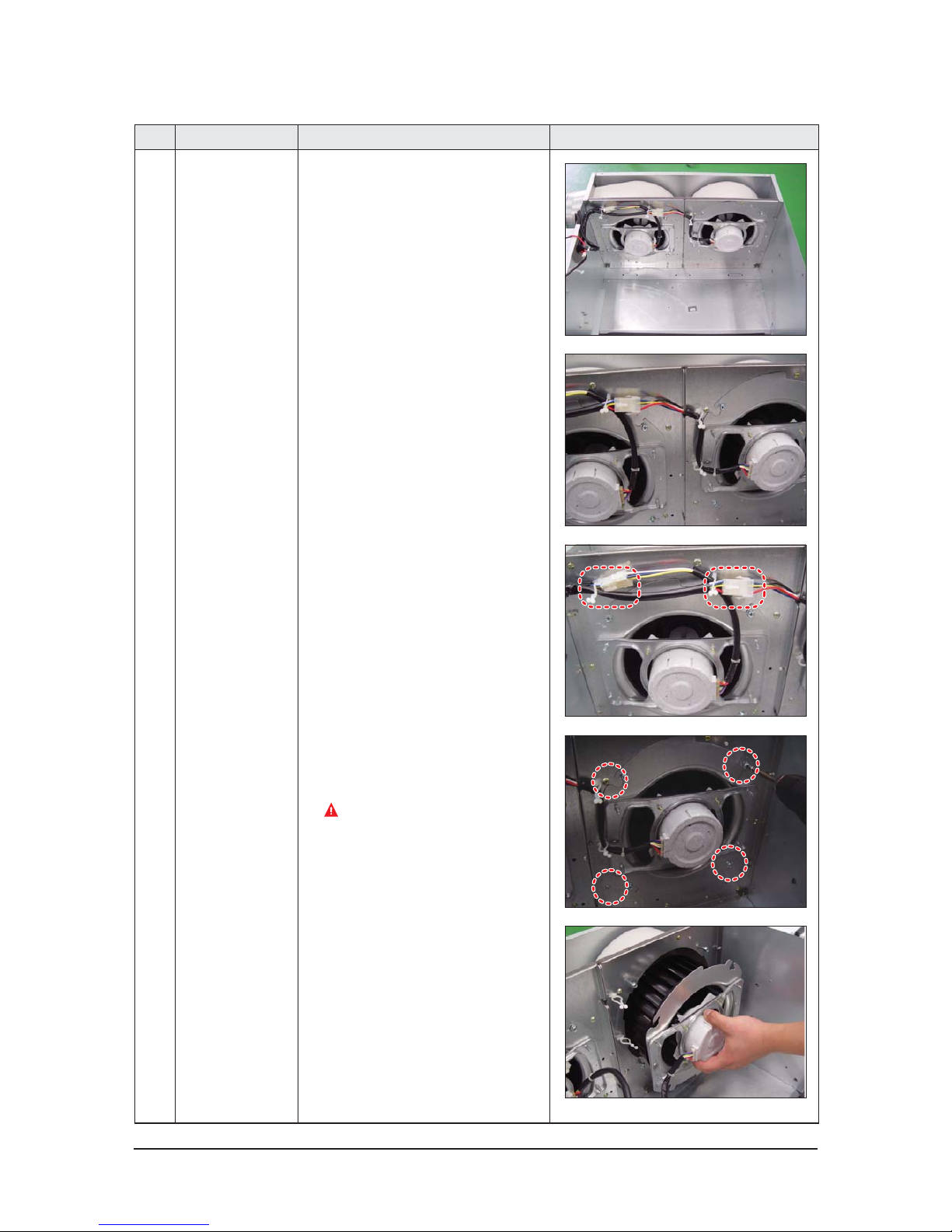
4-6 Samsung Electronics
No Parts Procedure Remark
9 Ass’y Blower Motor 1) Find Wire connected to the Motor.
Separate the 2 motor connectors.
2) Loosen the holders, fixing the motor wire
by twisting them slightly.
3) Rotate bolts fixing the Bracket 5 turns.
(Use +Screw Driver.) Supply air and exhaust
air of the products have 4 bolts each.
The bolts are not required to be removed.
4) Detach the whole Ass’y Blower Motor
(which is made up of Fan, Motor, Bracket
Motor, and Cover Bell Mouse).
5) 2 Motors are placed within the unit for
input and outlet.
Page 22
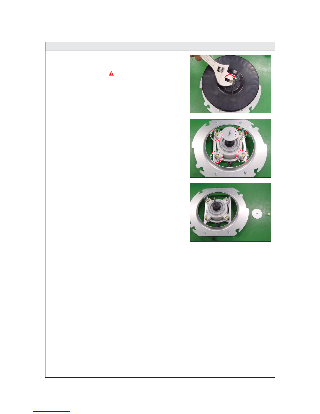
Samsung Electronics 4-7
No Parts Procedure Remark
10 Ass’y Blower 1) Unscrew the nuts fixing Fan by rotating
them right. (Use Monkey Spanner.)
Do not touch the Fan. Its sharp edge
may cause injury.
2) Detach the Motor with removing the 4
bolts fixing Bracket. (Use +Screw Driver.)
Page 23
4-8 Samsung Electronics
No Parts Procedure Remark
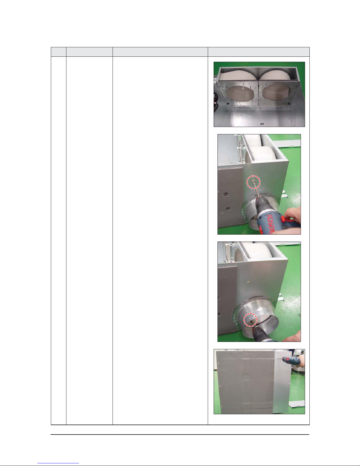
11 Ass’y Case Blower 1) Remove the 2 bolts attached at the sides of
the body. (Use +Screw Driver.)
2) Remove the 4 bolts on the other side
of Cabi Cover to detach it. (Use +Screw
Driver.)
Page 24
Samsung Electronics 4-9
No Parts Procedure Remark
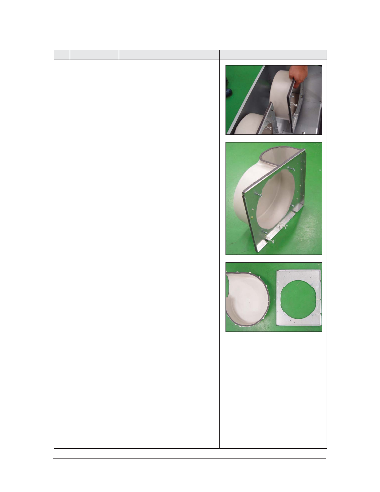
3) Detach the Ass’y Case Blower.
4) Unscrew the Bracket Case Blower and the
Case Blower. (Use +Screw Driver.)
Page 25
4-10 Samsung Electronics
No Parts Procedure Remark
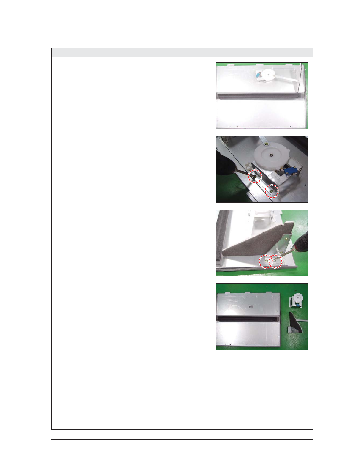
12 Ass’y Damper/
Ass’y-Lever Bypass
1) Remove all bolts to separate Bracket and
Cam. (Use +Screw Driver.)
Page 26
Samsung Electronics 4-11
No Parts Procedure Remark
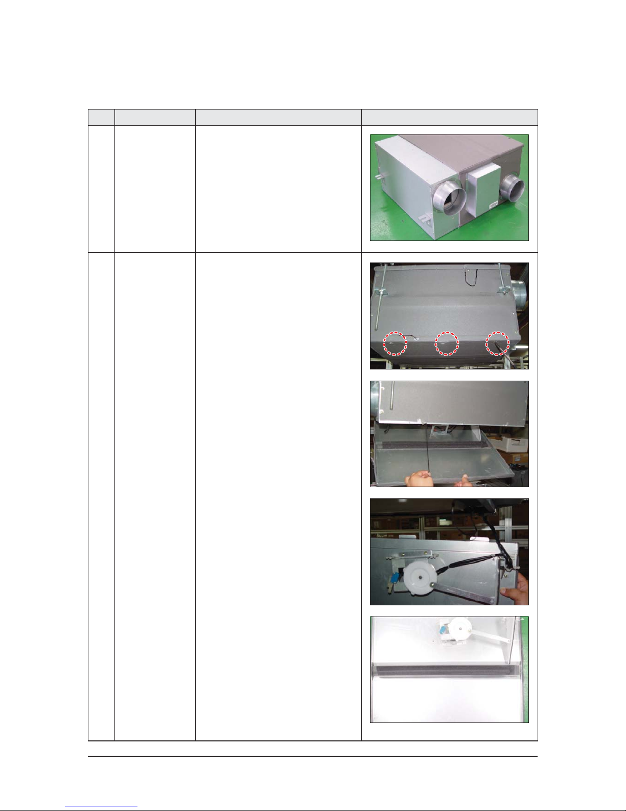
1 ERV
(Energy Recovery
Ventilator)
1) Stop the air conditioner operation and
shut off the main power.
2) Remove the unit from ceiling suspension.
(Disassembly is not required when Fan,
Motor, Element, Filter replacement or
cleaning.)
2
Ass’y Cabi
Cover Element
1) Remove the 3 bolts on Cover Element to
detach it.(Use +Screw Driver.)
2) Loosen the clips connected to the Cover.
3) Separate the connector connected to the
Damper by pulling out the connector body.
QProduct Disassembly (while still being installed)
Page 27
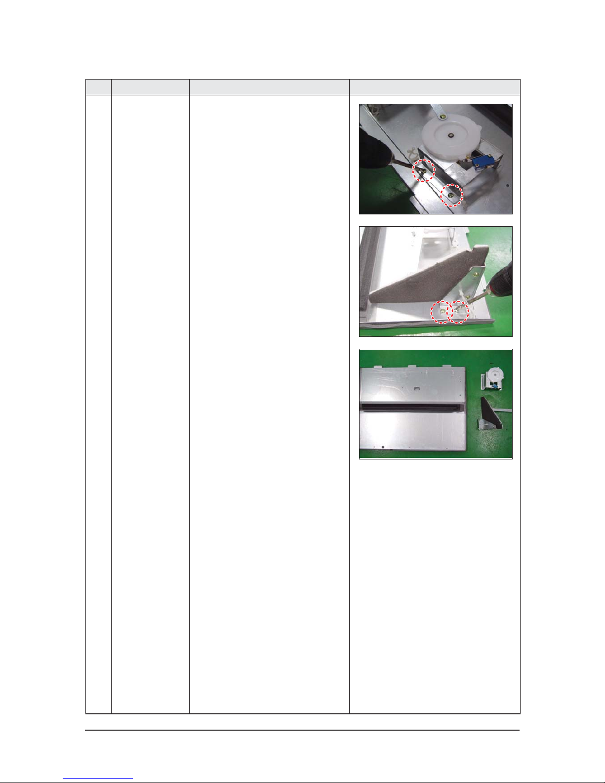
4-12 Samsung Electronics
No Parts Procedure Remark
Page 28
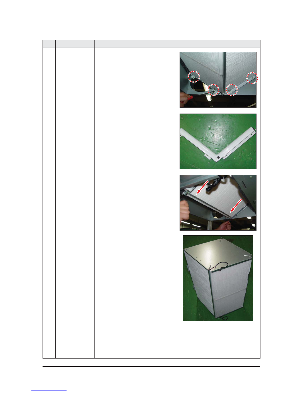
Samsung Electronics 4-13
No Parts Procedure Remark
3 Ass'y Element 1) Remove the 4 bolts and separate Bracket
Body Element, B. (Use +Screw Driver.)
2) Pull down the 2 strings hanging out
from the 2 ends of Element to detach
the Element.
Page 29
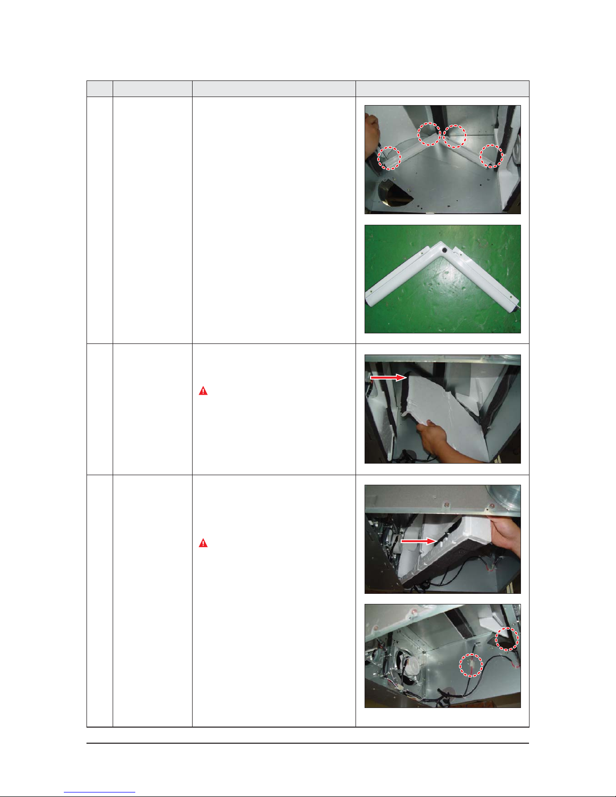
4-14 Samsung Electronics
No Parts Procedure Remark
4 Bracket Body
Element, A
1) Remove the 4 bolts and separate Bracket
Body Element, A. (Use +Screw Driver.)
5 Cushion Bypass 1) Slide Cushion Bypass to the direction
seen in the picture besides.
Take caution not to break down EPS
structure.
6 Cushion Mid 1) Slide Cushion Mid to the direction seen in
the picture besides.
2) Separate the 2 temperature sensor
connectors.
Take caution not to break down EPS
structure.
Page 30
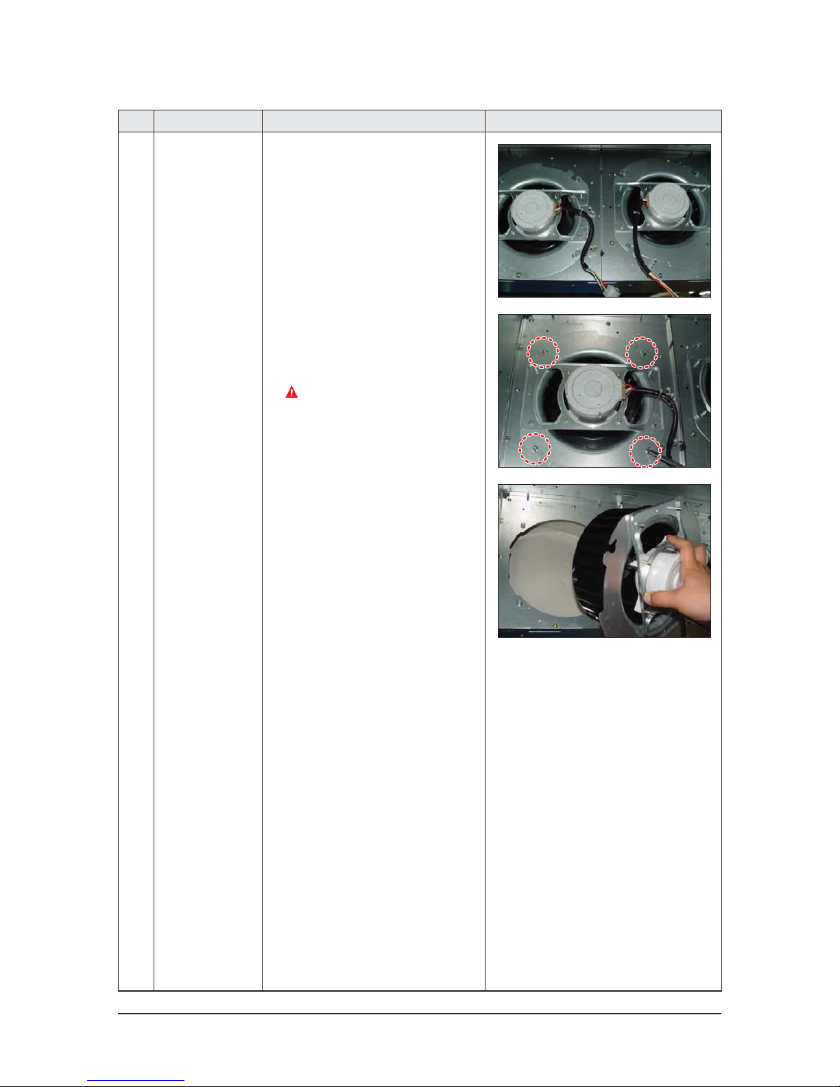
Samsung Electronics 4-15
No Parts Procedure Remark
7 Ass’y Blower Motor 1) Separate the 2 motor connectors.
2) Loosen the holders, fixing the motor wire
by twisting them slightly.
3) Rotate bolts fixing the Bracket 5 turns.
(Use +Screw Driver.)
Supply air and exhaust air of the products
have 4 bolts each.
The bolts are not required to be removed.
4) Detach the whole Ass’y Blower Motor
(which is made up of Fan, Motor, Bracket
Motor, and Cover Bell Mouse).
5) 2 Motors are placed within the unit for
input and outlet.
Page 31
4-16 Samsung Electronics
4-2 AN035JSKLKN/AN050JSKLKN/AN080JSKLKN/AN100JSKLKN
No Parts Procedure Remark
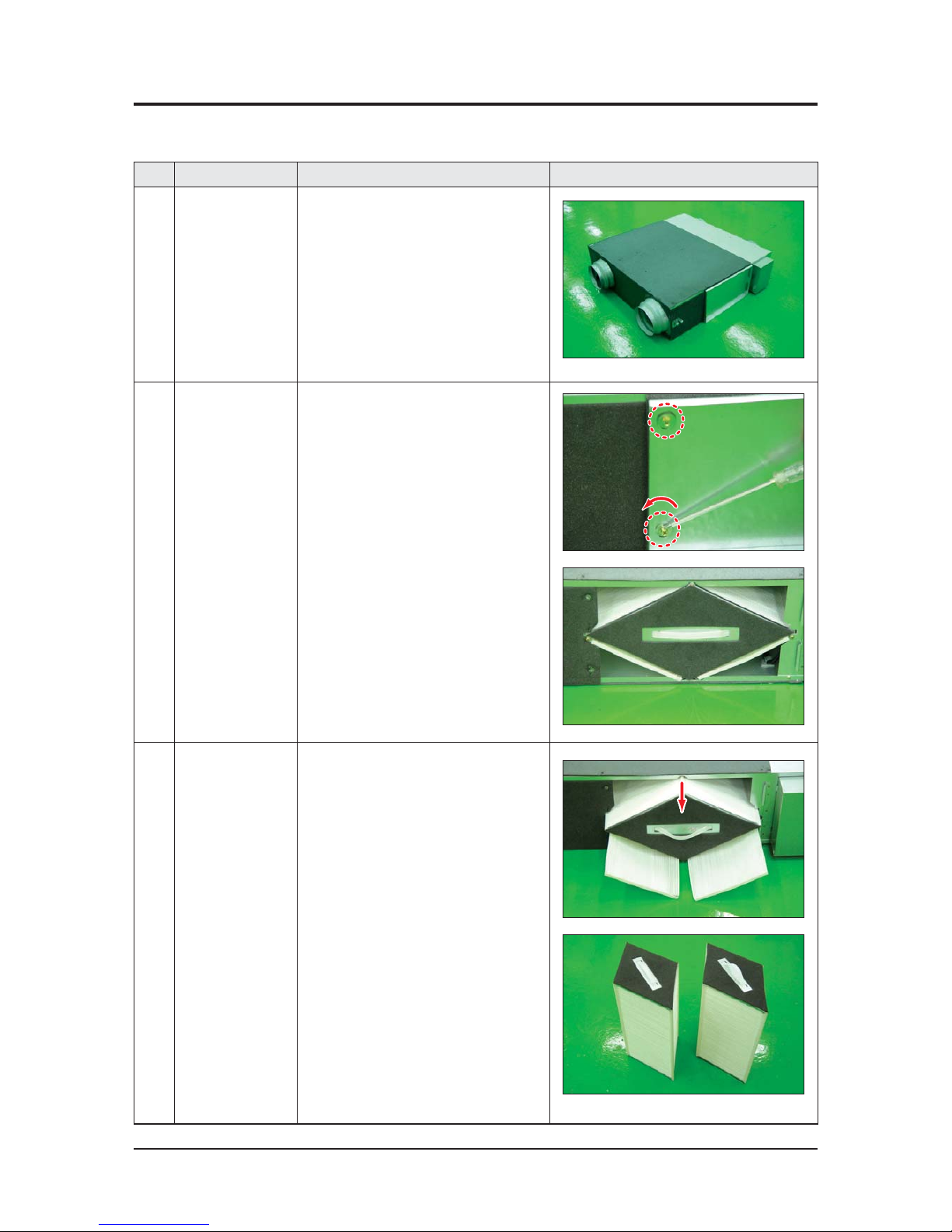
1 ERV
(Energy Recovery
Ventilator)
1) Stop the air conditioner operation and
shut off the main power.
2) Remove the unit from ceiling suspension.
(Disassembly is not required when Fan,
Motor, Element, Filter replacement or
cleaning.)
2
Cover Element 1) Remove the 2 bolts of the Cover Element.
(Use +Screw Driver.)
2) Find the Element and 2 Dust Filters.
3
Ass’y Element
Ass’y Filter
1) Detach Element and Filter from the unit.
Make sure detach the Filter before the
Element.
2) There are 2 Element within the product.
QDisassembly before Installation
Page 32
Samsung Electronics 4-17
No Parts Procedure Remark
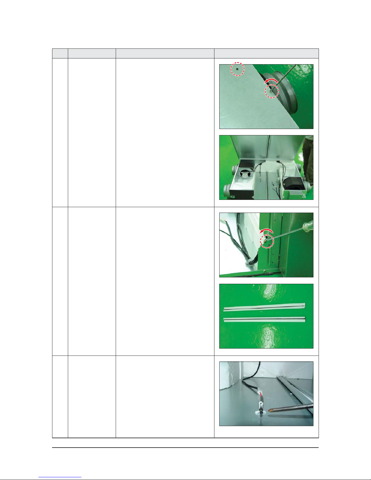
4 Cabinet Top 1) Loosen 12 bolts located at the top of the
product. (Use +Screw Driver.)
2) Locate the EPS structure, Fan, Motor and
Wire.
5 Guide Element 1) Separate the guides fixing Element.
(Use +Screw Driver.) 1 Guide is located
at each left and right end of the product.
Each guide is attached to the product with
1 bolt.
6 Thermistor
Ass'y Wire
1) Separate the Temperature Sensor from
the fixed part. The Temperature Sensor is
attached with wire clips.
2) The input and output channel has 1
Temperature Sensor each.
Page 33
4-18 Samsung Electronics
No Parts Procedure Remark
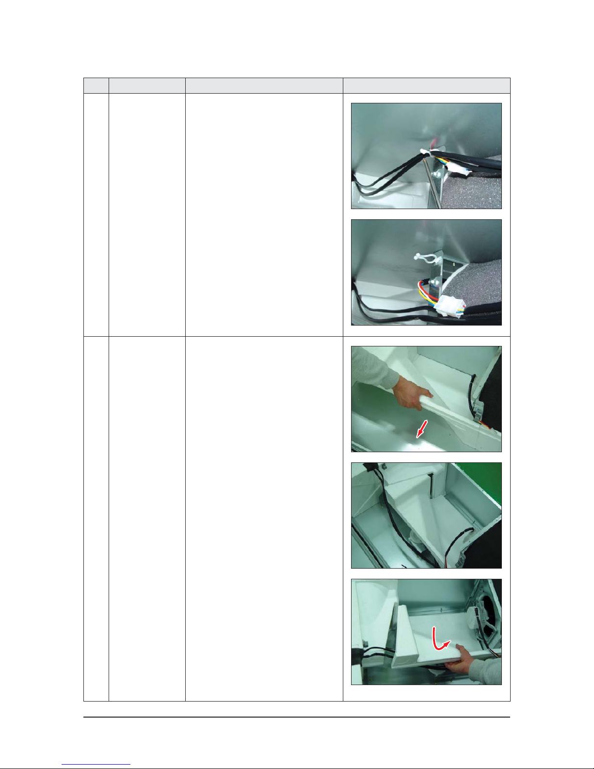
7 Ass’y Fan Parts 1) Separate motor connectors.
2) Loosen the holder fixing the motor wire
by twisting it slightly.
3) 2 Motors are placed within the product for
supply air and exhaust air.
8 Cushion Mid 1) Slide the EPS structure to the side and
detach it, as seen in the picture besides.
2) Slide and pull the EPS structure to separate
it, as seen in the picture besides.
Page 34
Samsung Electronics 4-19
No Parts Procedure Remark
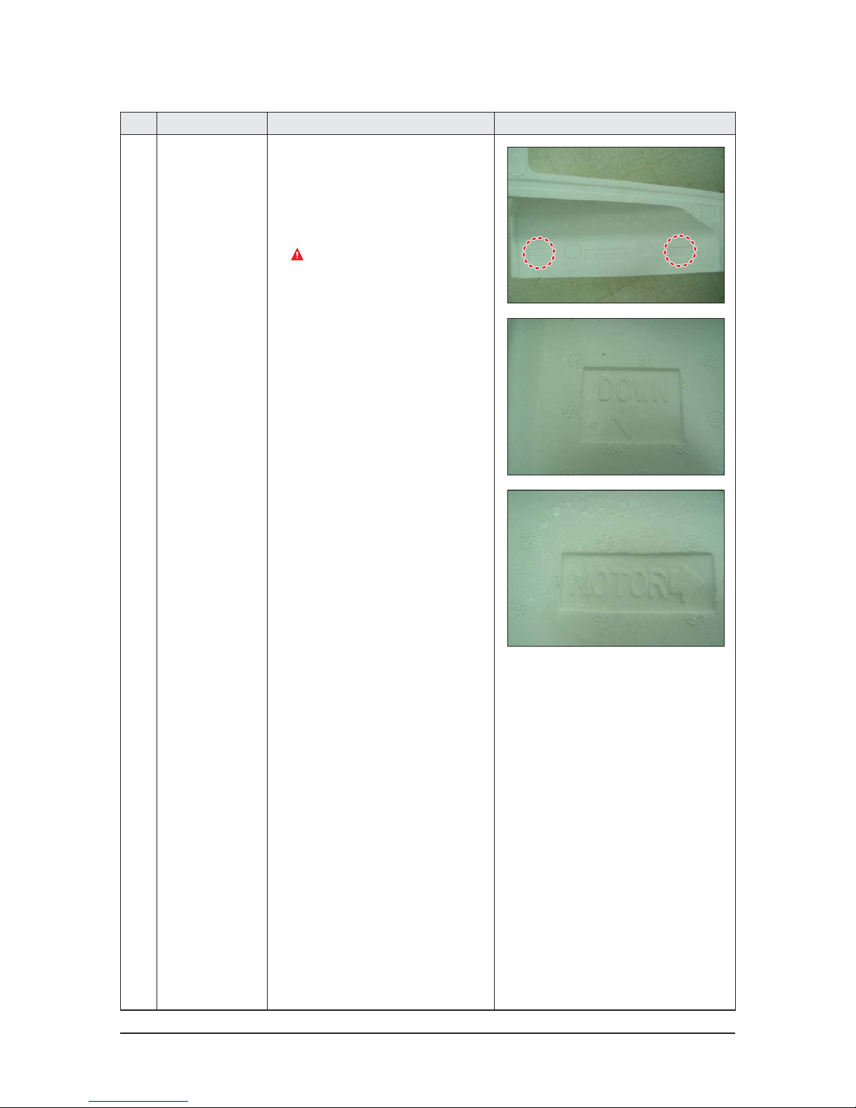
3) Assemble the product by adjusting it
with the direction, following the direction
carved on the surface of Cushion Mid. Put
the part written with “Down↓” downwards
and put the part with “Motor→” towards
the Motor when assembling the unit.
Make sure not to break down EPS
structure.
Page 35
4-20 Samsung Electronics
No Parts Procedure Remark
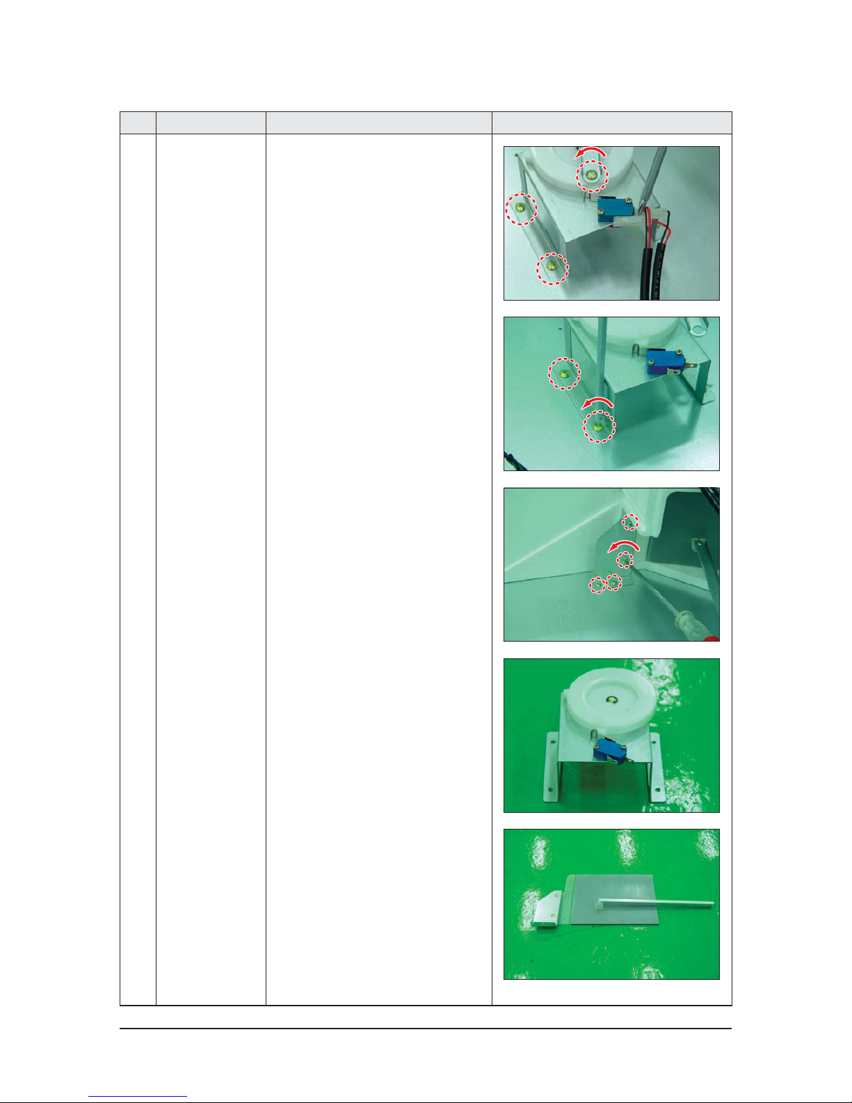
9 Connector
Damper Cam
1) Separate the Damper from the unit.
(Use +Screw Driver.)
2) Separate the connectors by holding their
bodies and pulling them out.
3) Unscrew bolts attached to Bracket and
Cam. (Use +Screw Driver.)
Page 36
Samsung Electronics 4-21
No Parts Procedure Remark
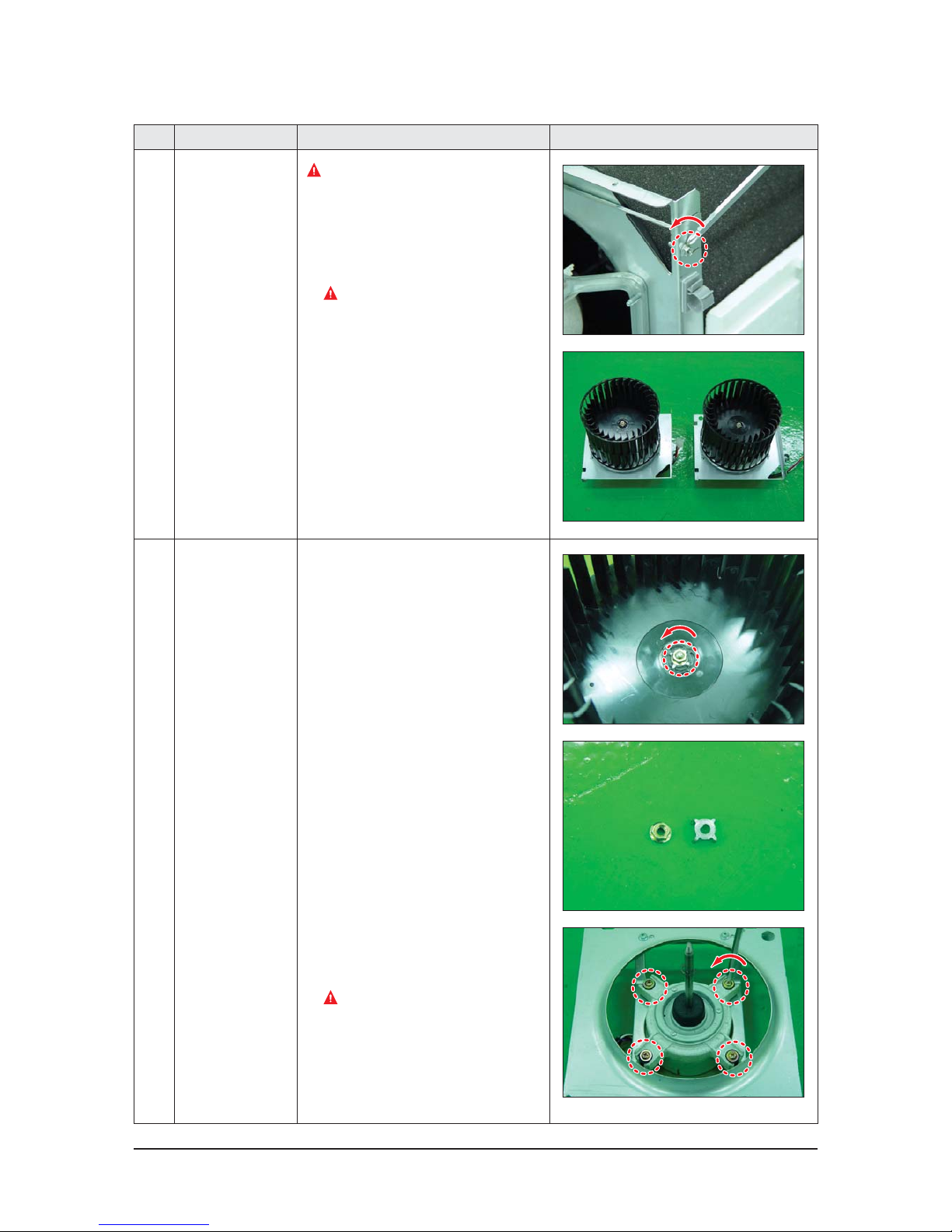
10 Ass’y Fan Parts
Ensure to separate the Damper before the
Fan.
1) Rotate bolts fixing the Bracket ten turns.
Input and outlet of the products have 2
bolts each. (Use +Screw Driver.)
The bolts are not required to be removed.
11 Blower Motor-Fan 1) Unscrew the nuts fixing the Fan by rotating
them left. (Use Monkey Spanner.)
2) Unscrew the bolts fixing Motor to detach
if from the Motor Bracket. It has 4 bolts.
(Use +Screw Driver.)
Do not touch the Fan. Its sharp edge
may cause injury.
Page 37
4-22 Samsung Electronics
No Parts Procedure Remark
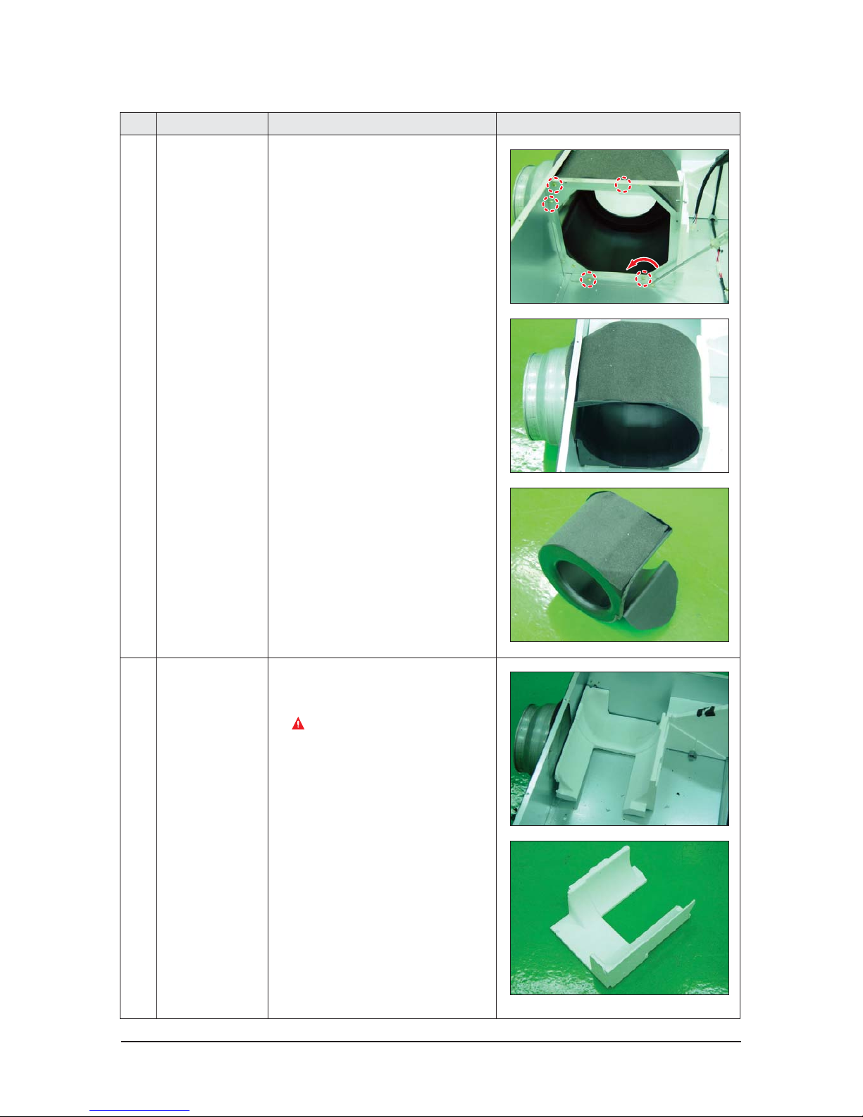
12 Case Blower 1) Separate the Bracket from Case Blower.
(Use +Screw Driver.)
There are 5 bolts.
2) Separate the Case Blower by sliding the
Case Blower upwards.
13 Cushion Blower-EA
Cushion Blower-SA
1) Detach the EPS structure fixed to Case
Blower by sliding the structure to the side.
Make sure not to break down the EPS
structure.
Page 38
Samsung Electronics 4-23
QProduct Disassembly (while still being installed)
No Parts Procedure Remark
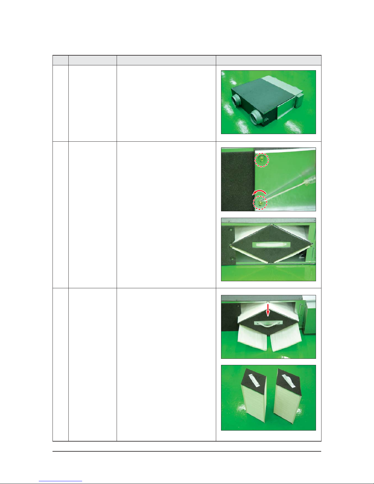
1 ERV
(Energy Recovery
Ventilator)
1) Stop the air conditioner operation and
shut off the main power.
2) Remove the unit from ceiling suspension.
(Disassembly is not required when Fan,
Motor, Element, Filter replacement or
cleaning.)
2
Cover Element 1) Remove the 2 bolts of the Cover Element.
(Use +Screw Driver.)
2) Find the Element and 2 Dust Filters.
3
Ass’y Element
Ass’y Filter
1) Detach Element and Filter from the unit.
Make sure detach the Filter before the
Element.
2) There are 2 Element within the product.
– All the procedure has to be verified because the cover should not open when the unit is installed.
Page 39
4-24 Samsung Electronics
No Parts Procedure Remark
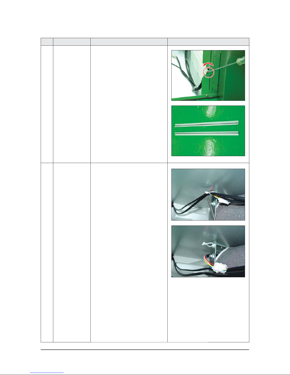
4 Guide Element 1) Separate the guides fixing Element.
(Use +Screw Driver.) 1 Guide is located
at each left and right end of the product.
Each guide is attached to the product with
1 bolt.
5 Ass’y Fan Parts 1) Separate motor connectors.
2) Loosen the holder fixing the motor wire
by twisting it slightly.
3) 2 Motors are placed within the product for
supply air and exhaust air.
Page 40
Samsung Electronics 4-25
No Parts Procedure Remark
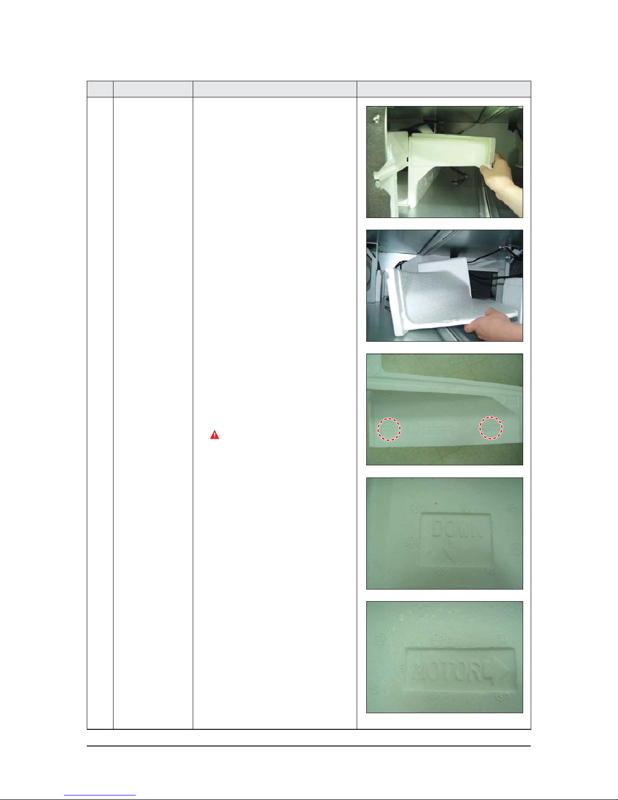
6 Cushion Mid 1) As seen in the picture besides, pull out
the EPS structure located at the center of
exhaust air and supply air.
2) Pull out the EPS structure through the
inspection hole.
3) Assemble the product by adjusting it
with the direction, following the direction
carved on the surface of Cushion Mid. Put
the part written with “Down↓” downwards
and put the part with “Motor→” towards
the Motor when assembling the unit.
Make sure not to break down EPS
structure.
Page 41
4-26 Samsung Electronics
No Parts Procedure Remark
7 Connector
Damper Cam
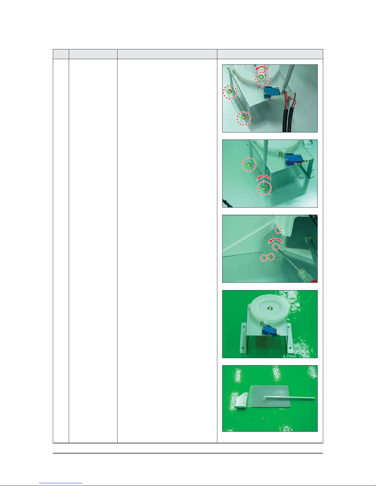
1) Separate the Damper from the unit.
(Use +Screw Driver.)
2) Separate the connectors by holding their
bodies and pulling them out.
3) Unscrew bolts attached to Bracket and
Cam. (Use +Screw Driver.)
Page 42
Samsung Electronics 4-27
No Parts Procedure Remark
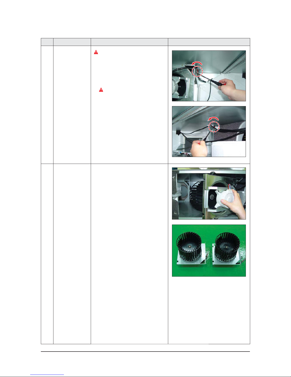
8 Ass’y Fan Parts
Ensure to separate the Damper before the
Fan.
1) Rotate bolts fixing the Bracket 10 turns.
Input and outlet of the products have 2
bolts each. (Use +Screw Driver.)
The bolts are not required to be removed.
9 Ass’y Bracket Motor 1) Detach the whole Ass’y Blower Motor
(which is made up of Fan, Motor, Bracket
Motor, and Cover Bell Mouse) through the
inspection hole.
2) 2 Motors are placed within the unit for
supply air and exhaust air.
Page 43
4-28 Samsung Electronics
No Parts Procedure Remark
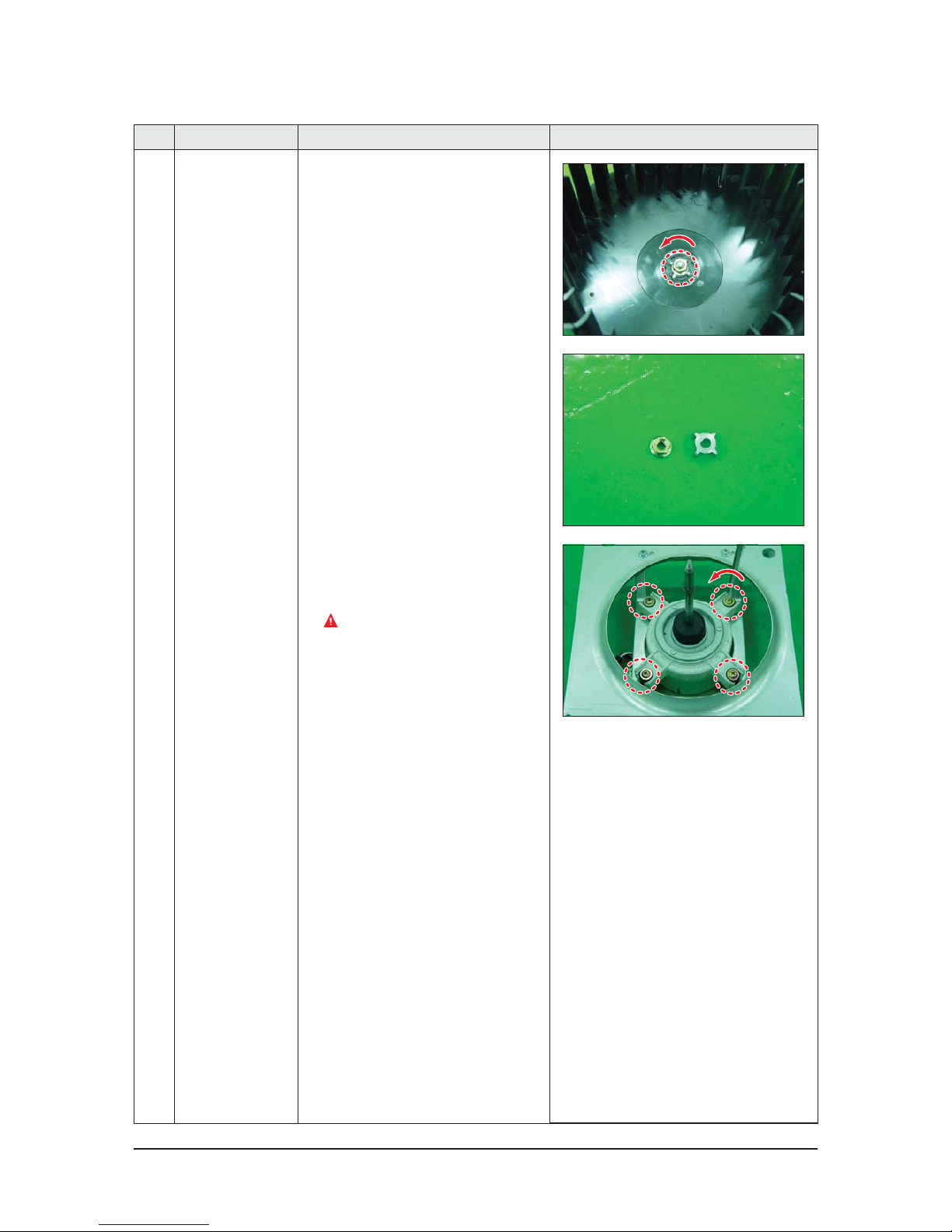
10 Blower Motor-Fan 1) Unscrew the nuts fixing the Fan by rotating
them left. (Use Monkey Spanner.)
2) Unscrew the bolts fixing otor to detach
if from the Motor Bracket. It has 4 bolts.
(Use +Screw Driver.)
Do not touch the Fan. Its sharp edge may
cause injury.
Page 44
Samsung Electronics 5-1
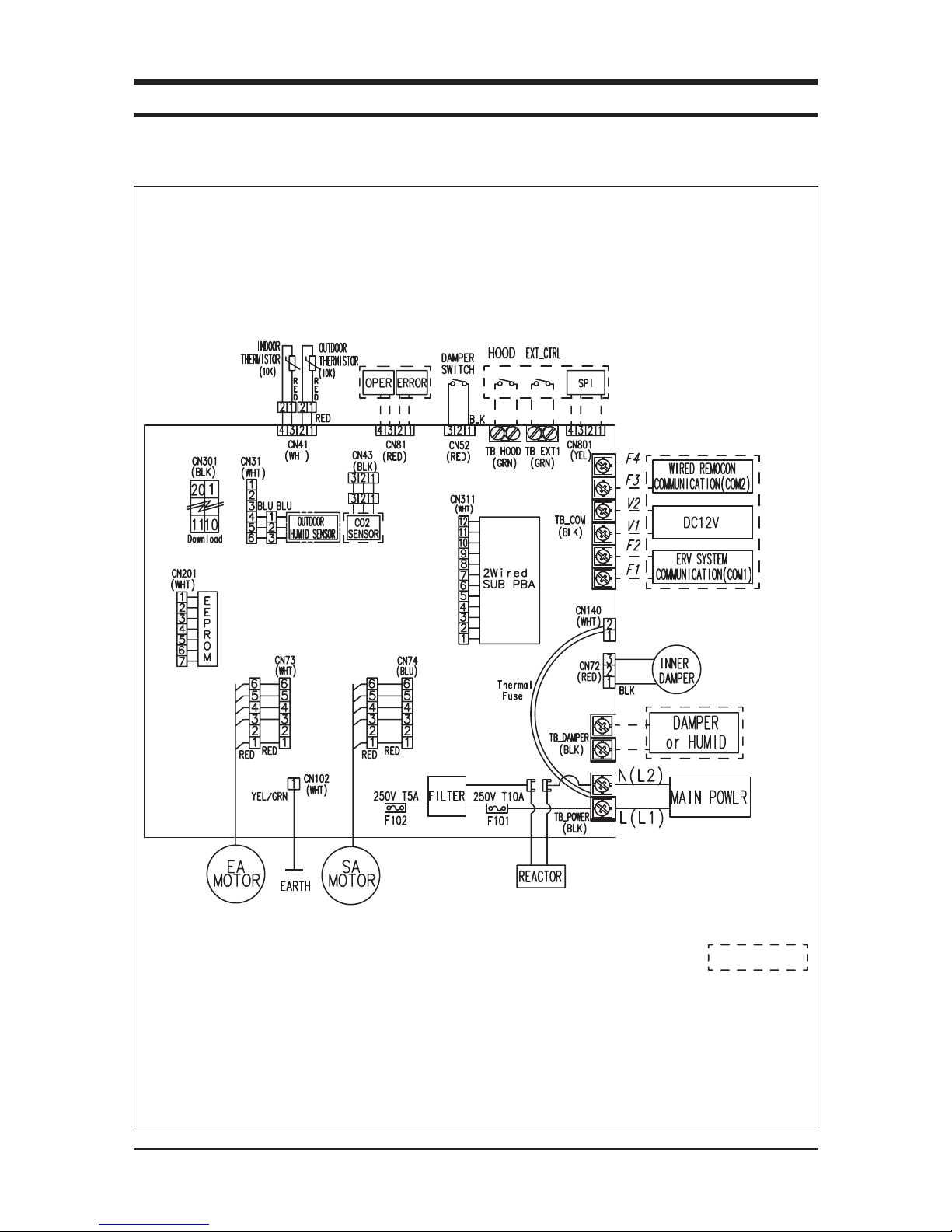
5. Wiring Diagram
Q AN026JSKLKN/AN035JSKLKN/AN050JSKLKN/AN080JSKLKN/AN100JSKLKN
This Document can not be used without Samsung’s authorization.
OPTIONOPTION
OPTION
OPTION
OPTION
OPTION:
Page 45
6-1 Samsung Electronics Samsung Electronics 6-2
6. Circuit Descriptions
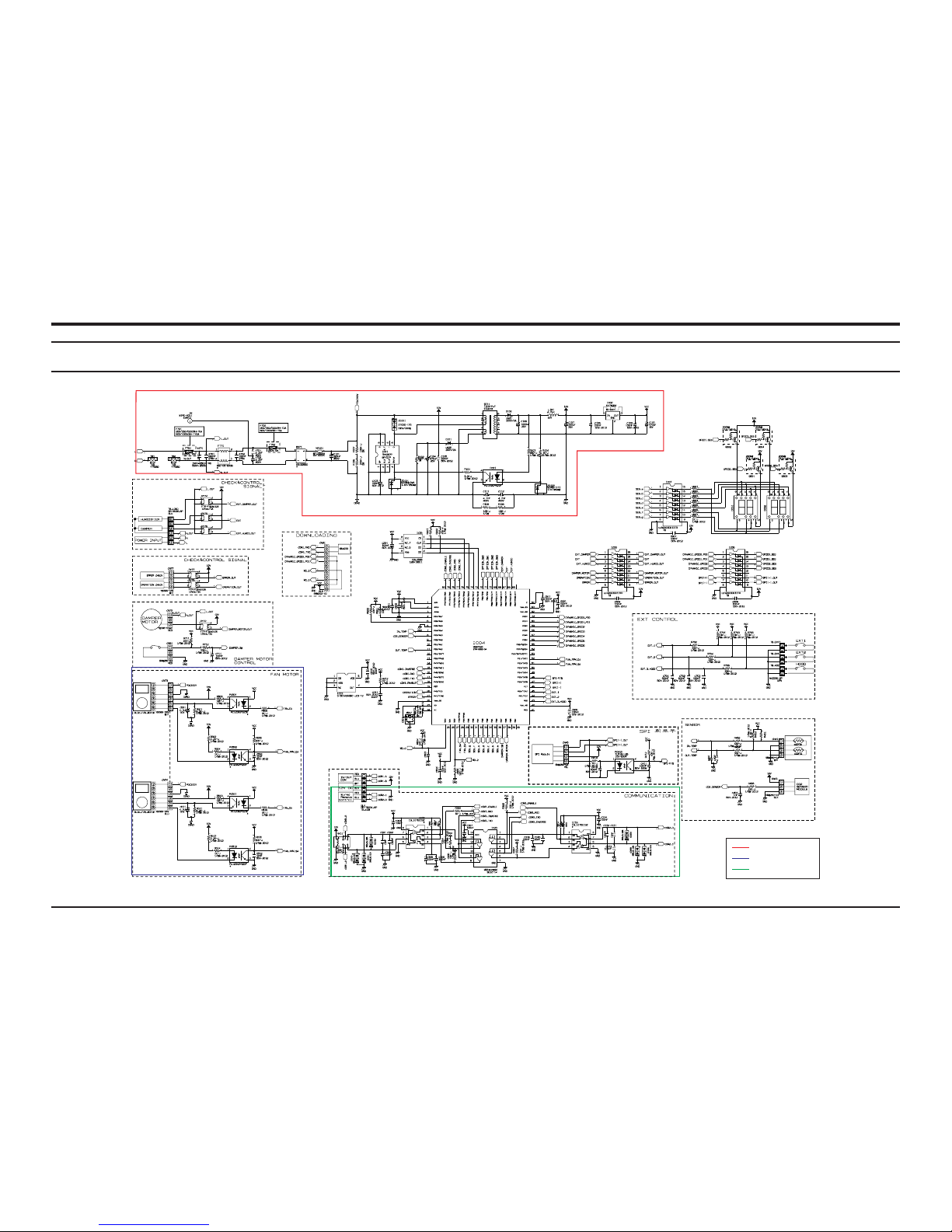
6-1 PCB Circuit Descriptions
This Document can not be used without Samsung’s authorization.
SMPS Circuit Part
Motor Load Circuit Part
Comm. Circuit Part
Page 46
6-3 Samsung Electronics
1. SMPS Part
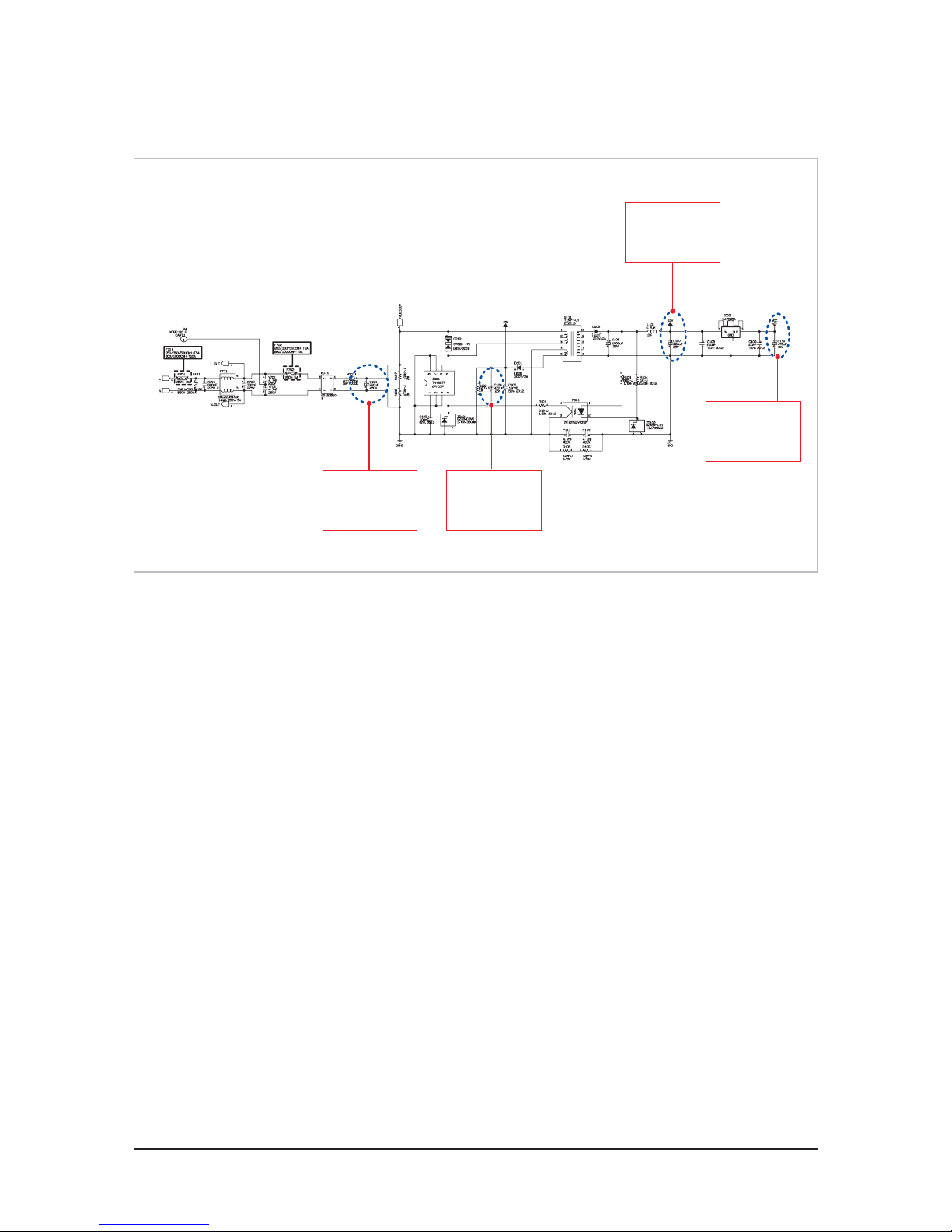
QSMPS(Switching Mode Power Supply) Part Description
1. BRIDGE DIODE (BD71) provides full wave reification from AC input. Then smooth it with Electrolytic Condenser(C101).
Smooth voltage is similar to the results of AC input x1.414. (Ex: When AC220V is supplied, 220x1.414 = about DC310V)
2. The main power supply of ventilator is DC310V as it utilizes BLDC MOTOR.
3. PWMIC (IC01) switches smooth DC voltage, which is, in turn, induced to secondary side, so as to generate DC15V (C104) and
DC12V(C107).
4. The voltage of secondary side is decided by TURN numbers of TRANS winding. DC 15V is utilized only for CONTROL power source
of BLDC MOTOR while DC12V is used for power source of CO
2 sensor.
5. When BLDC MOTOR faulty takes place, DC 15V or DC 12V might not be generated.
6. SWITCHING DIODE of secondary side should not utilize usual rectification DIODE because SWITCHING speed of SMPS reaches
130kHz. High speed SWITCHING DIODE is required.
7. SMPS stops operation if SHORT occurs post voltage of DC12V because of FEEDBACK from DC12V.
Both ends
voltage of C101:
Approximately
DC310V
Both ends
voltage of C104:
Approximately
DC15V
Both ends
voltage of C107:
Approximately
DC12V
Both ends
voltage of C110:
Approximately
DC5V
Page 47
Samsung Electronics 6-4
2. Motor Load Part
Q
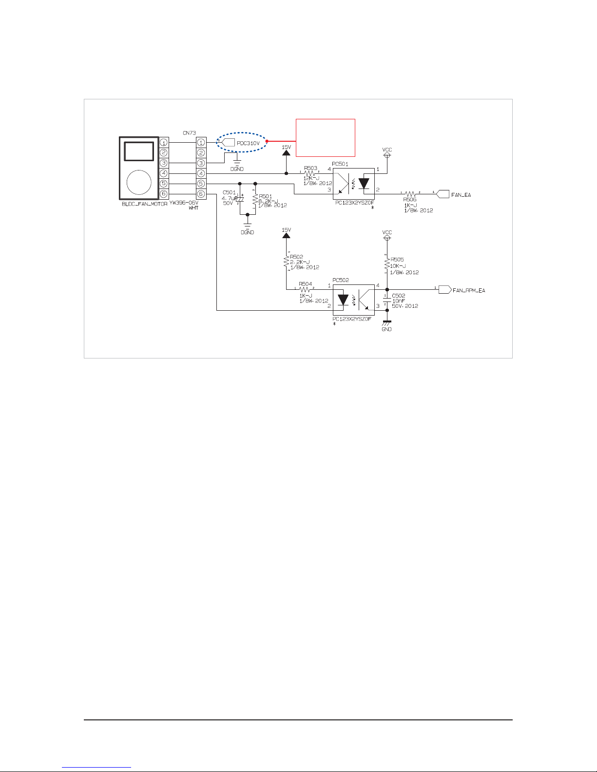
Motor Load(BLDC : BRUSHLESS MOTOR) Part Description
1. Smooth DC310V of electrolytic condenser (C101) is utilized for operation power source.
2. DC15V (C104) of secondary side of circulation is used for CONTROL voltage of MOTOR. BLDC CONTROL voltage must be lower
than MAX DC18V.
3. CONTROL voltage is distributed through No.5 PIN of CN73 and is lower than MAX DC7V. MOTOR RPM is determined by
DC0V~DC6V voltage.
4. No. 6 PIN of CN73 is the RPM FEEDBACK POINT, which delivers MOTOR rotation to MICOM. If DC15V continues to be found when
measuring DC15V and No.6 PIN, FAN MOTOR ERROR occurs because FEEDBACK is not conducted.
5. CONNECTOR of CN73 is dislocated when PCB power source is authorized, DC310V voltage may flow into CONTROL IC within BLDC
in a moment, damaging CONTROL IC of BLDC. It may cause SHORT of DC15V or DC310V.
6. If SHORT of DC15V or DC310V takes place, 2A FUSE (F702) opens and DC15V rectification DIODE may be damaged, which stops
operation of SMPS.
Both ends
voltage of C101:
Approximately
DC310V
Page 48
6-5 Samsung Electronics
3. Communication (485 Communication) Part
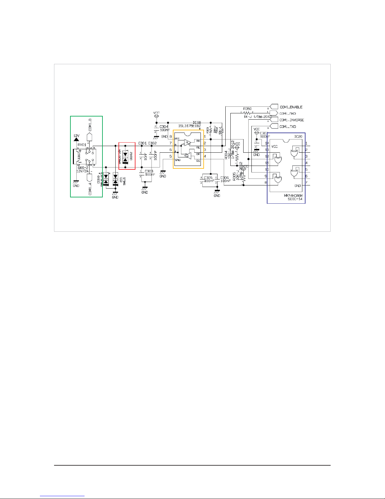
Q
Communication (485 Communication) Part Description
1. Faulty Connection Prevention RELAY: When AC220-240V, 50Hz power is supplied to power source link, 12V voltage is provided
to RELAY, so as to connect communication link. (Protect circulation in case of fault power source link or communication link.
2. SNUBBER Circulation: NOISE of over 5V is eliminated through SAC5.0 DIODE.
3. 485 IC (Line Driver/Reeceiver)
● HIGH / LOW is determined through voltage gap between the two electrodes of A and B.
: A-B>200mV : HIGH, B-A>200mV : LOW
● DATA is received and prepared with “R” PORT. When sending the DATA, HIGH is input at ENABLE.
4. EXCLUSIVE GATE
Non-polar communication realization element to change signal LEVEL with utilizing INVERSE when connections is switched.
1
2
3
4
Page 49
Samsung Electronics 7-1
7. PCB Diagram
5 6 7 8 9
10
11
17
16
4
3
1
12
13
18
14
15
2019
2
This Document can not be used without Samsung’s authorization.
Page 50
7-2 Samsung Electronics
5
6
7
8 9
10
11
17
16
4
3
1
12
13
18
14
15
20
19
2
This Document can not be used without Samsung’s authorization.
Page 51
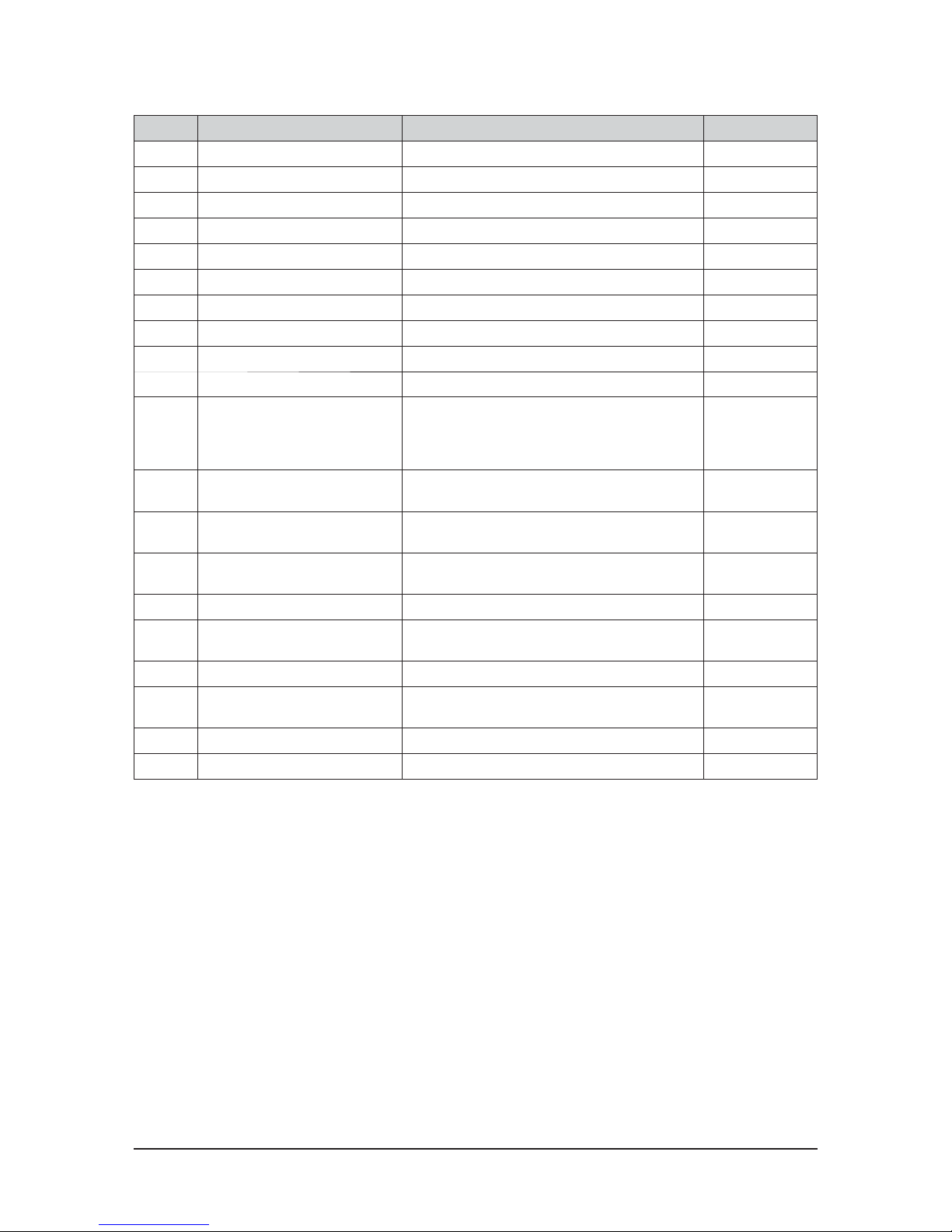
Samsung Electronics 7-3
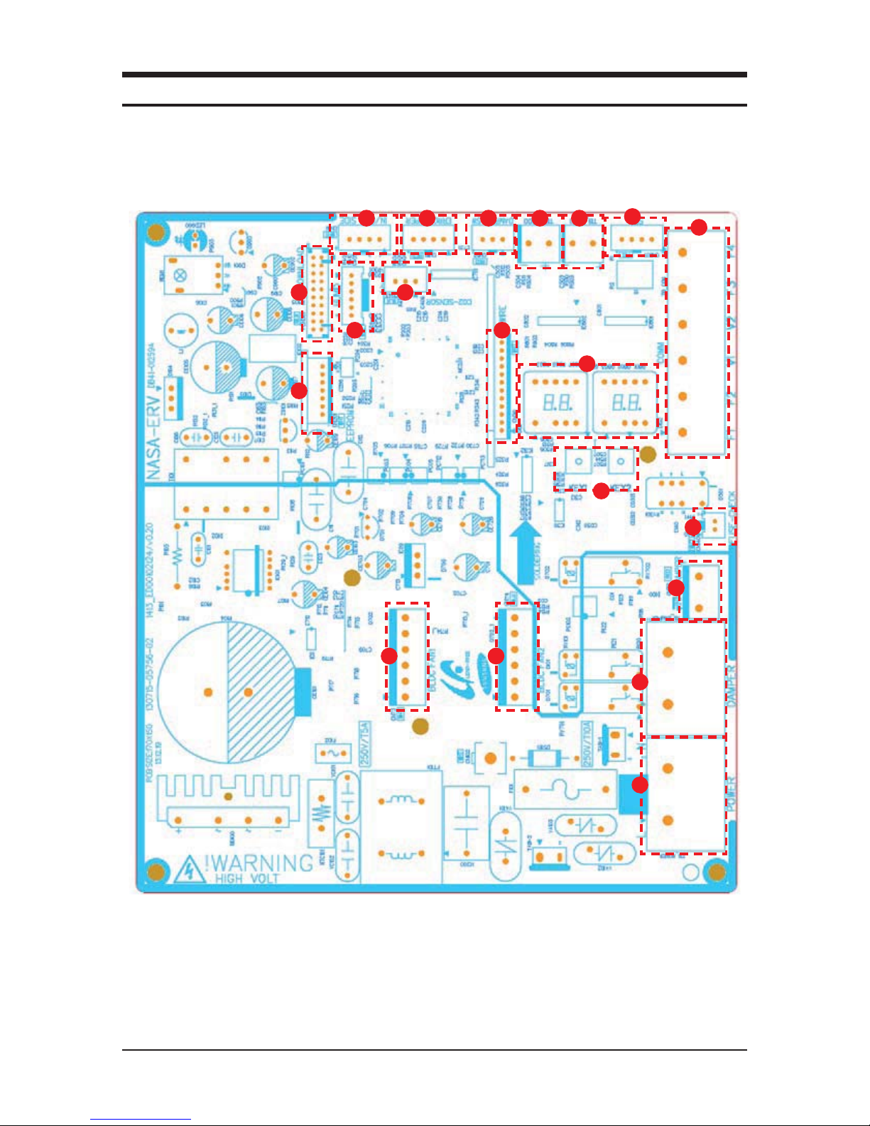
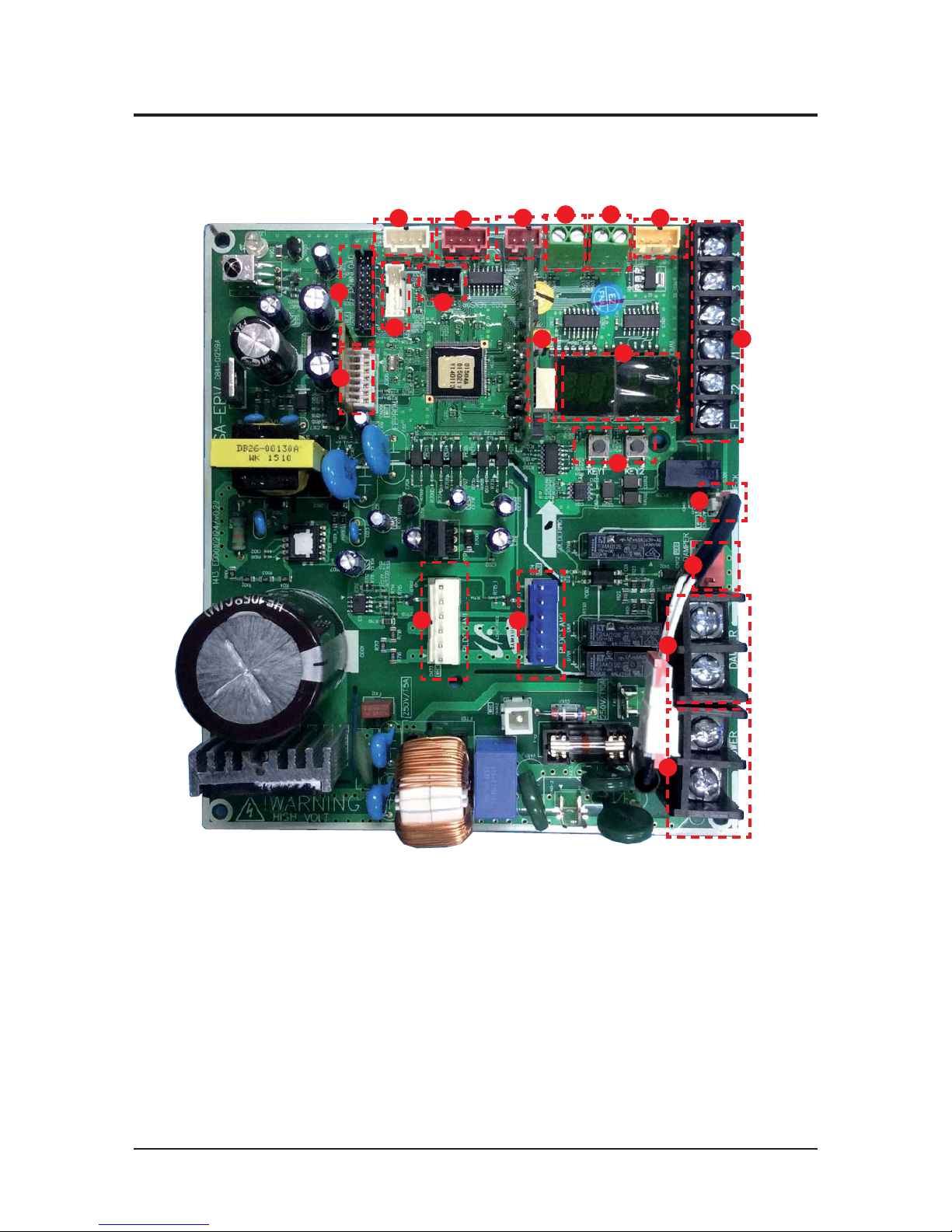
No. Part name Description Part No.
①
Download Program downloader connector CN301(BLK)
②
EEPROM SUB PBA - CN201(WHT)
③
Humidity sensor Outdoor humidity sensor connector CN31(WHT)
④
CO
sensor
CO
(Carbon dioxide) sensor connector CN43(BLK)
⑤
Temperature sensor Indoor and outdoor temperature sensor connector CN41(WHT)
⑥
Operation monitoring output Outputs operation status (Error/Operation ON) CN81(RED)
⑦
Internal damper switch Inputs damper switch contact signal CN52(RED)
⑧
External contact control part (HOOD) Turn on/off the HOOD mode via external contact TB_HOOD
⑨
External contact control part Turn on/off the via external contact TB_EXT1
⑩
Virus Doctor Virus Doctor kit connector CN801(YEL)
⑪
Communication connection part
F1, F2(Communication between ventilation systems,
communicate with interface module)
V1, V2(Power supply connector for interface module)
F3, F4(Wired remote controller communication)
TB_COMM(BLK)
⑫
Thermal Fuse status input connector
Inputs status of Thermal Fuse within the power terminal
block
CN140(WHT)
⑬
Internal damper power supply
Damper motor control part for switching ventilation
mode
CN72(RED)
⑭
External damper / Humidity power
supply
External damper and Humidity power supply connector TB_DAMPER(BLK)
⑮
Power supply input 220 V/ 60 Hz TB_POWER(BLK)
⑯
2 wire communication (wired remote
controller) SUB PBA
- CN311(WHT)
⑰
Display part Display part -
⑱
KEY input part
KEY input part to execute trial operation, reset or view
mode
-
⑲
Exhaust motor EA (Exhaust air) motor connector CN73(WHT)
⑳
Supply motor SA (Supplied air) motor connector CN74(BLU)
Page 52
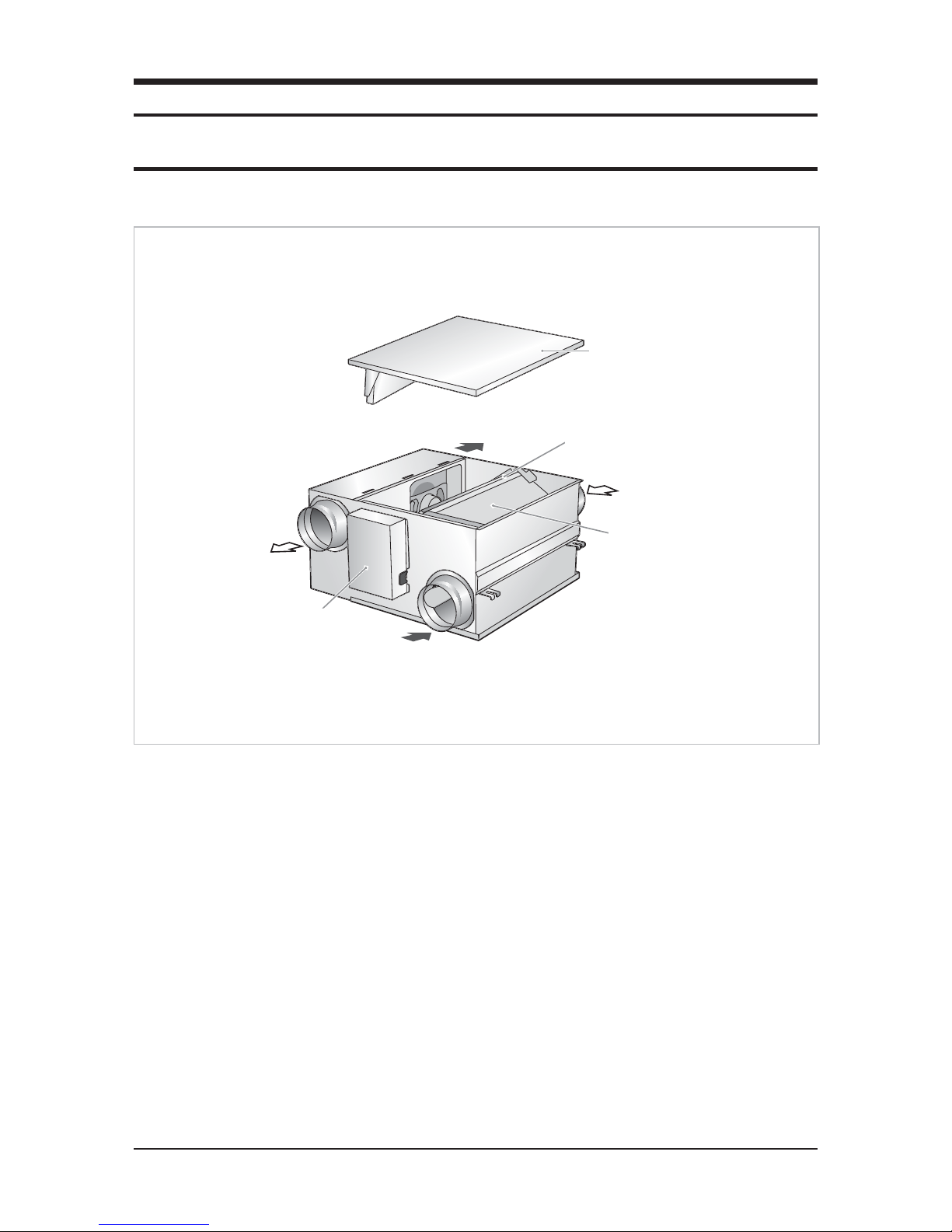
Samsung Electronics 8-1
Q AN026JSKLKN
8. Operating Instructions
8-1 Name of Each part
Q Heat Exchange Element
It refers the medium required to exchange temperature and humidity of exhaust air and supply air.
Q Air Input and Outlet
Air input is to supply air while outlet is for exhaust air.
Q DAMPER
It refers to separation shed to switch from heat exchange mode to Usual Ventilation mode or vice versa.
Q Dust Filter
Dust filter protects heat exchange element and filter supplied air.
Q Electric Component Box
It is made up of circulation of the unit.
Q Duct Connection Flange
It refers to the pipe connected to the duct for supply air, outdoor air, indoor air and exhaust air.
Outdoor Air
Maintenance cover
Electrical component box
Return Air
Heat exchange element
Supply Air
Exhaust Air
Dust filter
Page 53
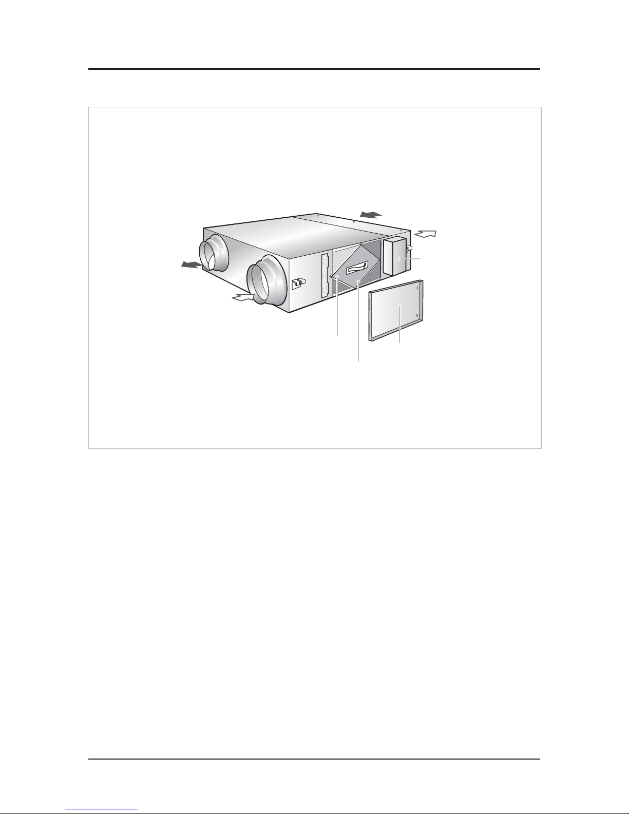
8-2 Samsung Electronics
Q AN035JSKLKN/AN050JSKLKN/AN080JSKLKN/AN100JSKLKN
Name of Each part(cont.)
Q Heat Exchange Element
It refers the medium required to exchange temperature and humidity of exhaust air and supply air.
Q Air Input and Outlet
Air input is to supply air while outlet is for exhaust air.
Q DAMPER
It refers to separation shed to switch from heat exchange mode to Usual Ventilation mode or vice versa.
Q Dust Filter
Dust filter protects heat exchange element and filter supplied air.
Q Electric Component Box
It is made up of circulation of the unit.
Q Duct Connection Flange
It refers to the pipe connected to the duct for supply air, outdoor air, indoor air and exhaust air.
Outdoor Air
Supply Air
Dust filter
Maintenance cover
Electrical component box
Return Air
Exhaust Air
Heat exchange element
Page 54
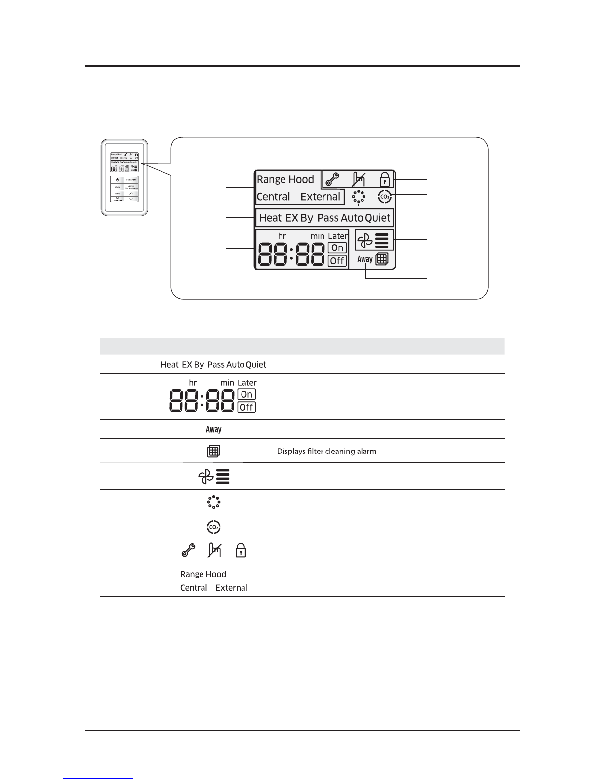
Samsung Electronics 8-3
Name of Each part(cont.)
Q Display
①
⑨
②
③
⑥
⑤
⑦
⑧
④
Classification Indication Function
①
Displays operation mode
②
Displays set time
③
Displays Away mode
④
⑤
Displays fan speed
⑥
Displays SPI (Optional)
⑦
Displays CO2 sensor (Optional)
⑧
Displays inspection, invalid, and lock
⑨
Displays range hood, central control and external interlock
Page 55
8-4 Samsung Electronics
Name of Each part(cont.)
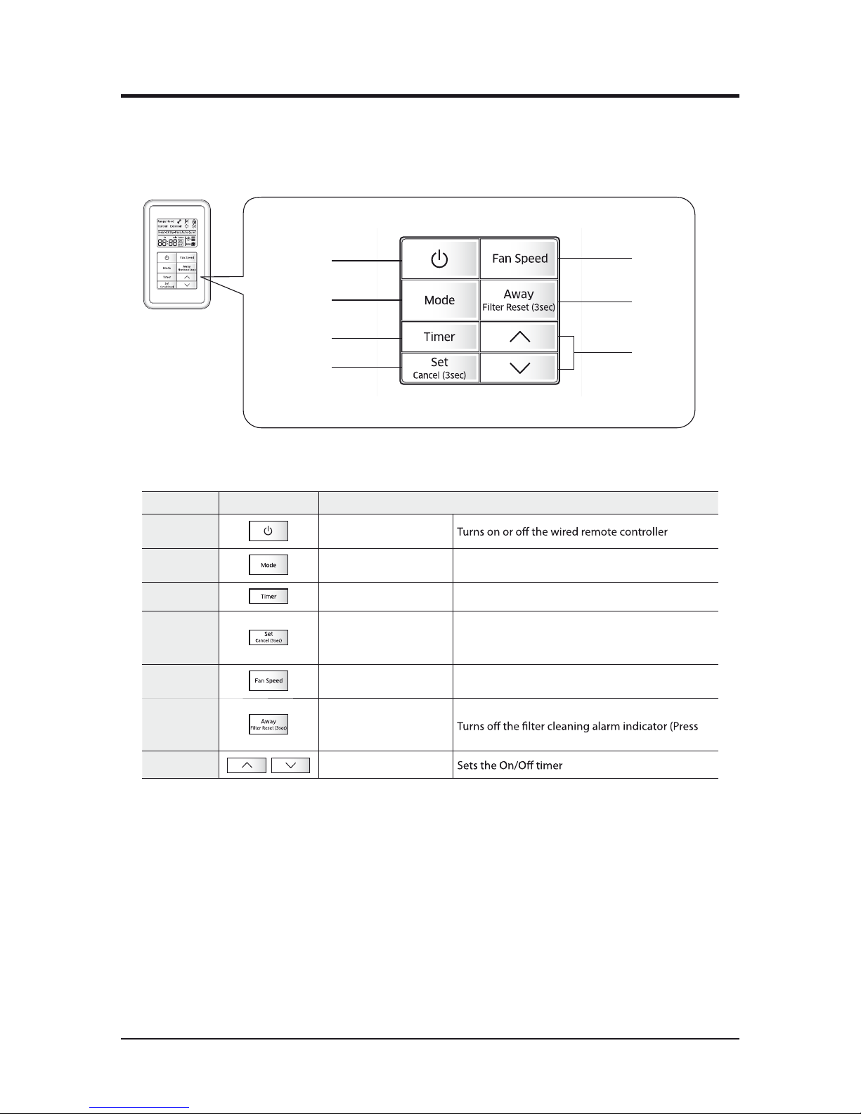
Q Buttons
①
②
③
④
⑤
⑥
⑦
Classification Button Function
①
Power button .
②
Mode button Selects the mode you want to operate
③
Schedule button Sets the timer function.
④
Set/Cancel button
Completes the timer function/
Cancels the timer function (Press the button for
more than 3 seconds.)
⑤
Fan speed button Adjusts the fan speed.
⑥
Away/Filter reset button
Selects the Away mode/
the button for more than 3 seconds.)
⑦
,
Time control button .
Page 56
Samsung Electronics 8-5
8-2 Using installation/service mode of ERV wired remote controller
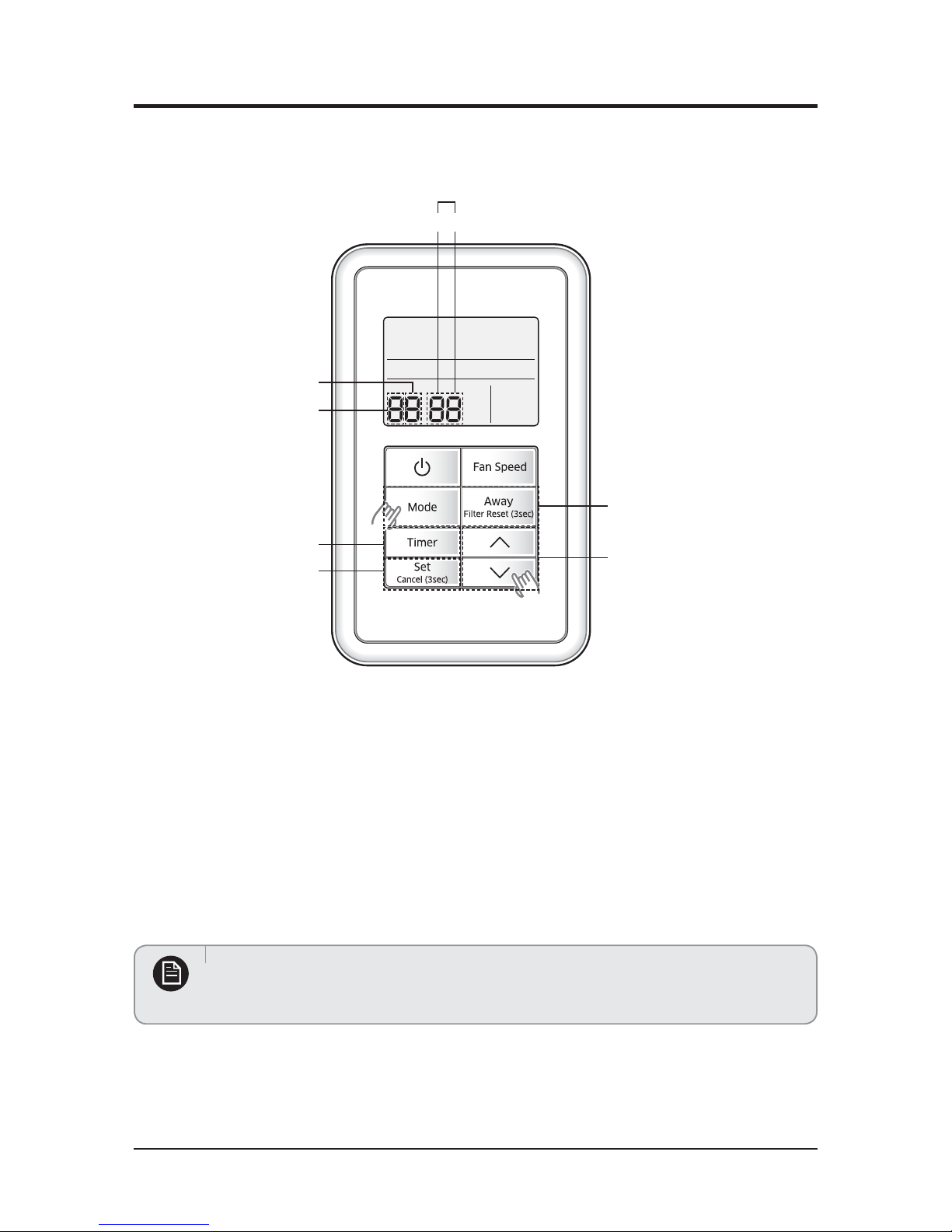
Q Additional functions of ERV wired remote controller
SEG used
Main menu
Exit
Set, Cancel
Up and down
Left and right
Sub menu
12
1. If you want to use the various additional functions for the ERV wired remote controller, press the Mode and ∧
buttons at the
same time for more than three seconds.
ඖ You will enter the additional function settings, and the main menu is displayed.
2. Refer to the list of additional functions for the ERV wired remote controller on the next page, and select the desired menu.
ඖ Using the
∨/∧
buttons, select a main menu number and press the Away button to enter the sub-menu setting screen.
ඖ Using the
∨/∧
buttons, select a sub-menu number and press the Away button to enter data setting screen.
ඖ When you enter the setting stage, the current setting is displayed.
ඖ Refer to the chart for data settings.
ඖ Using the
∨/∧
buttons, select the settings and press the Away button to move to the next setting.
ඖ Press the Set button to save the settings and exit to the sub-menu setting screen.
ඖ Press the Timer button to exit to normal mode.
t8IJMFTFUUJOHUIFEBUBQSFTTUIFMode or Away button to move the digit of SEG.
t*GZPVQSFTTUIFTimer button while your are setting data, you can exit to the sub-menu setting stage without saving
your changes.
Note
Page 57
8-6 Samsung Electronics
Using installation/service mode of ERV wired remote controller(cont.)
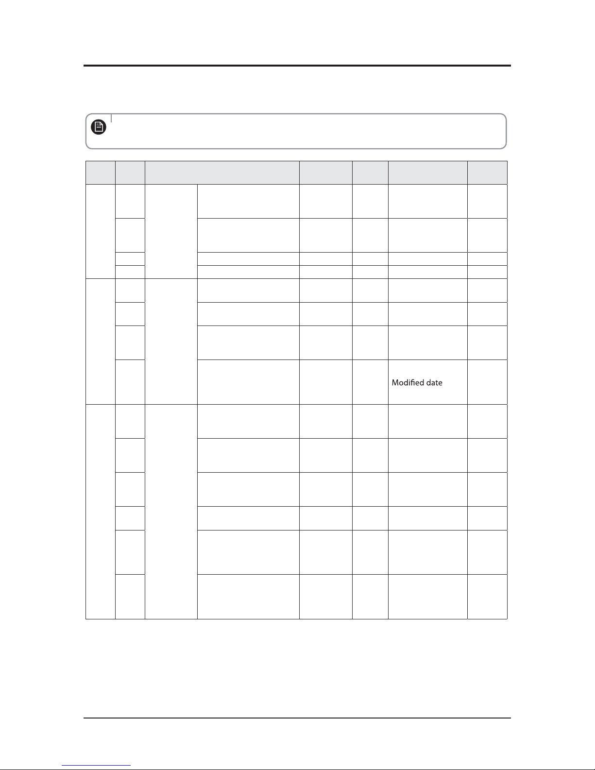
Q Installation/service setting mode
t If communication initialization is needed after the setting, the system resets automatically and
communication is initialized.
Note
Main
menu
Sub
menu
Function
Factory
setting
Page
number
Range Remarks
0
1
Reset
Reset to default value
of ERV wired remote
controller option setting
010-Disuse, 1-Reset
2
Reset to factory setting
of ERV wired remote
controller
010-Disuse, 1-Reset
3 Power Master Reset 3)* 0 1 0-
Disuse, 1-Reset
4 Addressing Reset 010-Disuse, 1-Reset
1
1
Information
on ERV
wired
remote
controller
Checking the number of
connected indoor units
0 1 0~16 EA
2
Checking the number of
connected ERVs
0 1 0~16 EA
3
Checking the Micom
code of ERV wired remote
controller
none 3 Micom code
4
Checking the program
version information
of ERV wired remote
controller
none 3
2
1
Setting
address/
option 2)*
Target
ERV View
Master
3
Address of
registerd devices /
hexadecimal 5)*
2
Setting/checking main
address
Main
address of
target
1
Main address
(00H~4FH/
hexadecimal)
3
Setting/checking RMC
address
RMC
address of
target
1
Group address
(00H~FEH/
hexadecimal) 4*
4
Setting/checking product
option
Basic option
of target
10 1)*
Option code of
indoor units or ERVs
5
Setting/Checking
installation option 1
Installation
option of
target
10 1)*
Refer to the
installation manual
of connected
indoor units or ERVs
6
Setting/Checking
installation option 2
Installation(2)
option of
target
10 1)*
Refer to the
installation manual
of connected
indoor units or ERVs
Page 58
Samsung Electronics 8-7
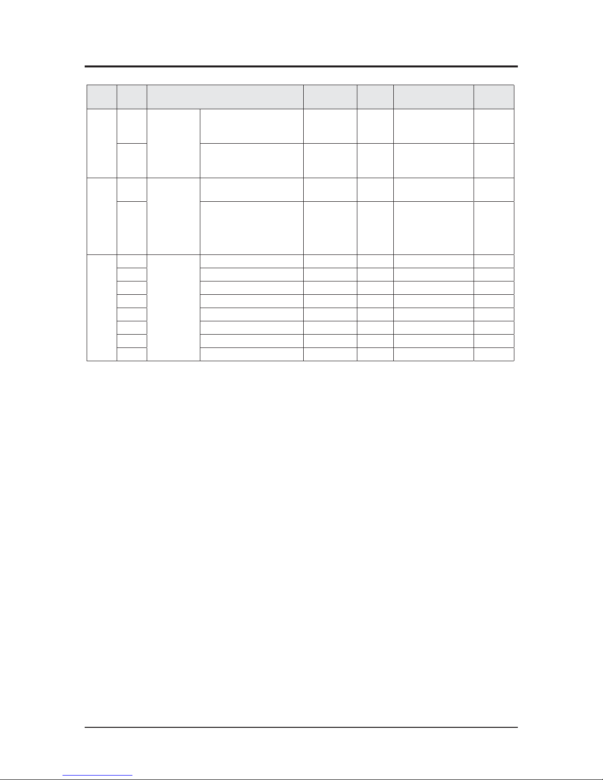
Using installation/service mode of ERV wired remote controller(cont.)
Main
menu
Sub
menu
Function
Factory
setting
Page
number
Range Remarks
3
1
Setting/
checking
View Master
Setting/checking indoor
unit View Master
Indoor unit
View Master
3
Address of
registered devices /
hexadecimal 5)*
None
2
Setting/checking ERV
View Master
ERV View
Master
3
Address of
registered devices /
hexadecimal 5)*
4
1
Setting/
checking
optional
functions of
ERV wired
remote
controller
ERV wired remote
controller Master/Slave
010-Master, 1-Slave
2Use of external interlock0 10-Disuse, 1-Use
5
1
Setting/
checking
ERV
Exhaust RPM none 2 0~9999
2Intake
RPM none 2 0~9999
3 Indoor temperature none 1 0~99
4 Outdoor temperature none 1 0~99
5Indoor humidity none 1 0~99
4 Outdoor himidity none 1 0~99
5 CO
2
sensor none 2 0~9999
6 FAN Step 6)* none 10~31
Page 59
8-8 Samsung Electronics
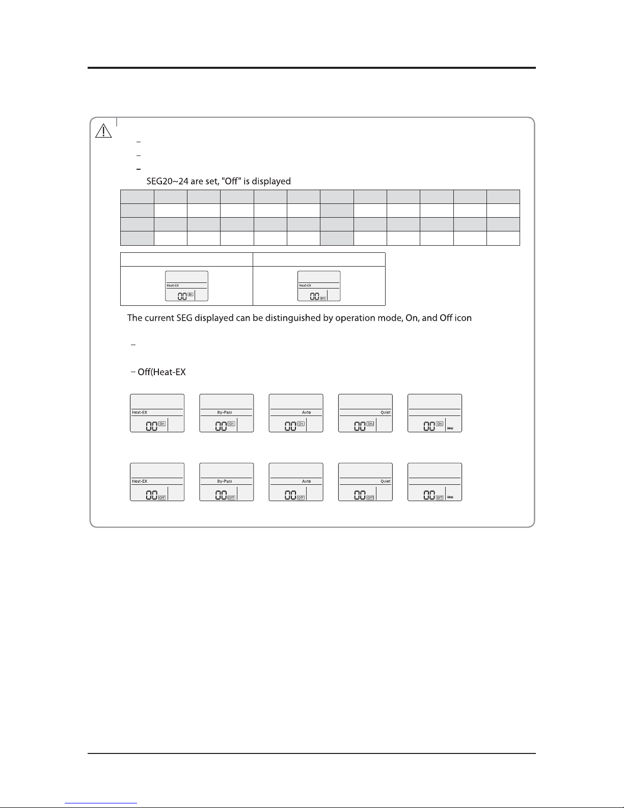
1) * The total option codes are 24 digits. You can set six digits at a time and it is distinguished by page number.
Press the Timer button to go to the next page.
t Options can be set from SEG1 to SEG24
SEG1, SEG7, SEG13, and SEG19 are page option so they cannot be set nor be displayed
SEG2 is the option type which cannot be set
When SEG2~SEG6 and SEG8~SEG12 are set, "On" is displayed and when SEG14~18 and
.
SEG1 SEG2 SEG3 SEG4 SEG5 SEG6 SEG7 SEG8 SEG9 SEG10 SEG11 SEG12
0XXXXX1XXXXX
SEG13SEG14SEG15 SEG16 SEG17 SEG18 SEG19 SEG20 SEG21 SEG22 SEG23SEG24
2XXXXX3 XXXXX
On (SEG2~SEG6, SEG8~SEG12) Off (SEG14~18, SEG20~24)
t .
SEG2~SEG6, SEG8~SEG12
On(Heat-EX By Pass Auto Quiet Away)
SEG14~SEG18, SEG20~24
By Pass Auto Quiet Away)
p
<SEG 2, 3>
PAGE 1
PAGE 6
PAGE 2
PAGE 7
PAGE 3
PAGE 8
PAGE 4
PAGE 9
PAGE 5
PAGE 10
<SEG 14, 15>
<SEG 4, 5>
<SEG 16, 17>
<SEG 6, 8>
<SEG 18, 20>
<SEG 9, 10>
<SEG 21, 22>
<SEG 11, 12>
<SEG 23, 24>
p
p
p
p
p
pp
p
Caution
2) * When setting the address or option, you can set the target device with sub menu no.1.
3) * Power Master Reset is a setting needed to supply optimized power to ERV wired remote controller when multiple indoor units or
ERVs are connected to ERV wired remote controller in a group.
4) * RMC(1) : 0~F / RMC(2) : 0~F (hexadecimal)
When RMC(1) is F, RMC(2) can be set up to E. (RMC(1) : Group channel, RMC(2) : Group address)
5) * Displaying address of ERVs (hexadecimal display) e.g. 30 00 0B
6) * Fan step setting is available only when one ERV is connected.
Using installation/service mode of ERV wired remote controller(cont.)
Page 60
Samsung Electronics 8-9
Using installation/service mode of ERV wired remote controller(cont.)
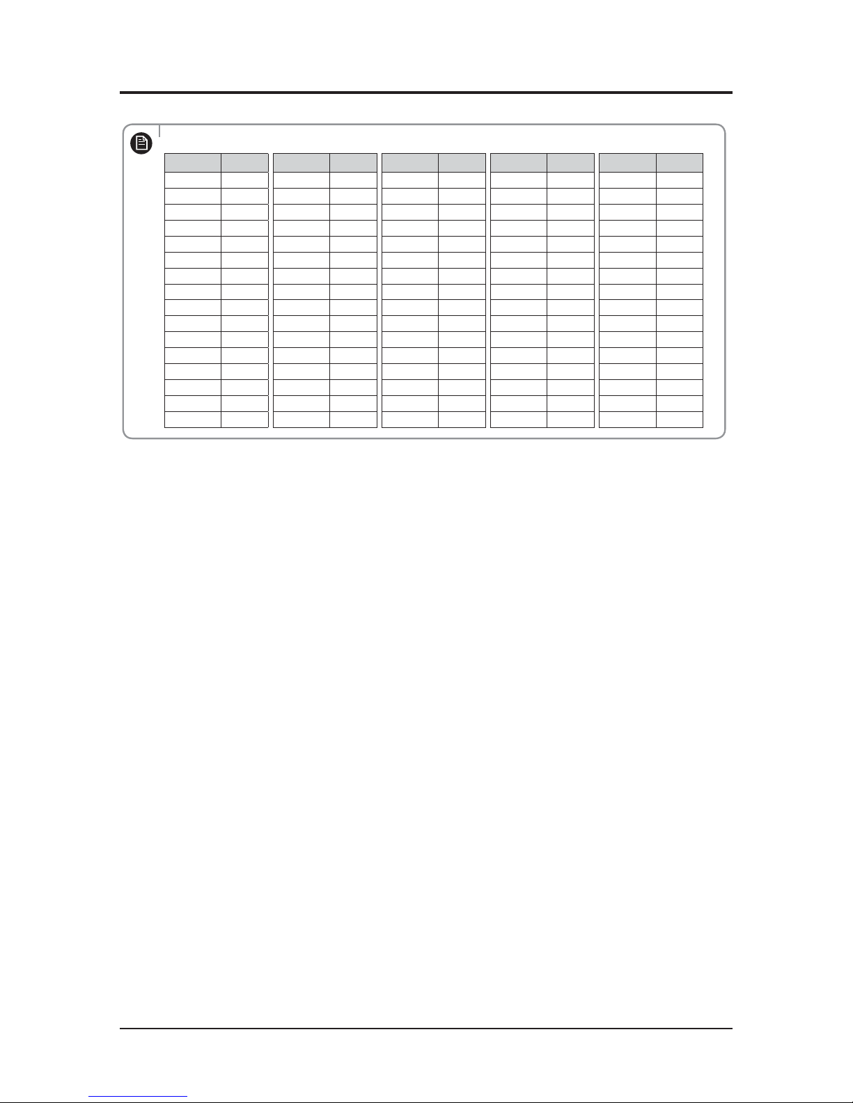
t Address is displayed in hexadecimal. Refer to the table below.
Hexadecimal
Decimal
Hexadecimal
Decimal
Hexadecimal
Decimal
Hexadecimal
Decimal
Hexadecimal
Decimal
00 0 10 16 20 32 30 48 4064
01 1 11 17 21 33 31 49 4165
02 2 12 18 22 34 3250 4266
033 13 19 2335 33 51 43 67
044 14 20 2436 34 52 44 68
05 5 15 21 25 37 35534569
06 6 16 22 26 38 36544670
07 7 17 23 27 39 3755 4771
08 8 18 24 28 40 3856 4872
09 9 19 25 29 41 3957 4973
0A 10 1A 26 2A 42 3A58 4A74
0B 11 1B 27 2B 43 3B59 4B75
0C
12 1C 28 2C44 3C60 4C 76
0D 13 1D 29 2D45 3D 61 4D 77
0E 14 1E 302E46 3E62 4E78
0F 15 1F 312F47 3F634F79
Note
Page 61
8-10 Samsung Electronics
Using installation/service mode of ERV wired remote controller(cont.)
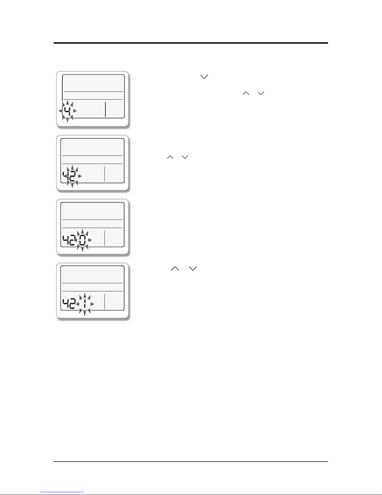
Q The example of setting ERV wired remote controller options
1. Press the Mode and buttons at the same time for more
than 3 seconds.
▶ When main menu is displayed, press the or button to select no.5.
2. Press the Away button to select the number you will set on
the sub menu.
▶ Press the or button to select no.1
3. Press the Away button to enter the data setting stage.
▶ When you enter the setting stage, the current setting is displayed .
4. Press the or button to select no.1
▶ The status of external interlock changes from "Disuse" to "Use".
5. Press the Set button to complete the option settings.
▶ Save the setting value and exit to sub menu .
6. Press the Timer button to exit to normal mode.
Page 62
Samsung Electronics 9-1
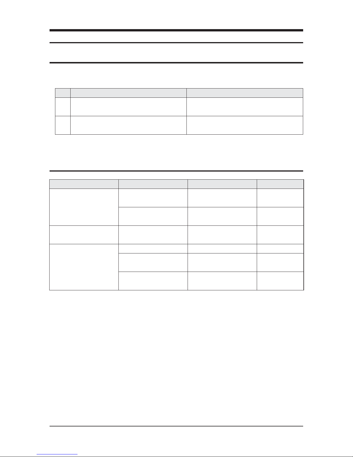
1. Check the voltage. Power voltage must be within the range of AC187V~AC253V/60Hz.
2. Claims of the following table are not related to product disorder.
No. Ventilator Operation Explanation
1
Air volume is not controlled while sleeping mode is being
operated.
Air volume is controlled automatically when sleep mode is
selected.
2
The unit stops operation for a while when operation mode is
changed.
While adjusting operation mode, MOTOR stops working. When
mode change completes, MOTOR operation restarts.
Trouble Cause Solution Remark
If the product is not turned on
Check electric power content and
wire
Fix power supply
Check FUSE disconnection Replace FUSE
A FUSE is provided in
PBA
If the remote control is not working Check remote control connection
Connect or replace connection wire
of remote control
If supply air fan or exhaust air fan are
not working
Check fan motor Check assembly or replace motor
Check whether outdoor temperature
is below -15˚C
Wait until the outdoor temperature
reaches -15˚C
Operation at cold places
Check outdoor temperature sensor
(SHORT/OPEN)
Replace sensor
9. Troubleshooting
9-1 Items to be checked first
9-2 When ventilator stops operation
Page 63
9-2 Samsung Electronics
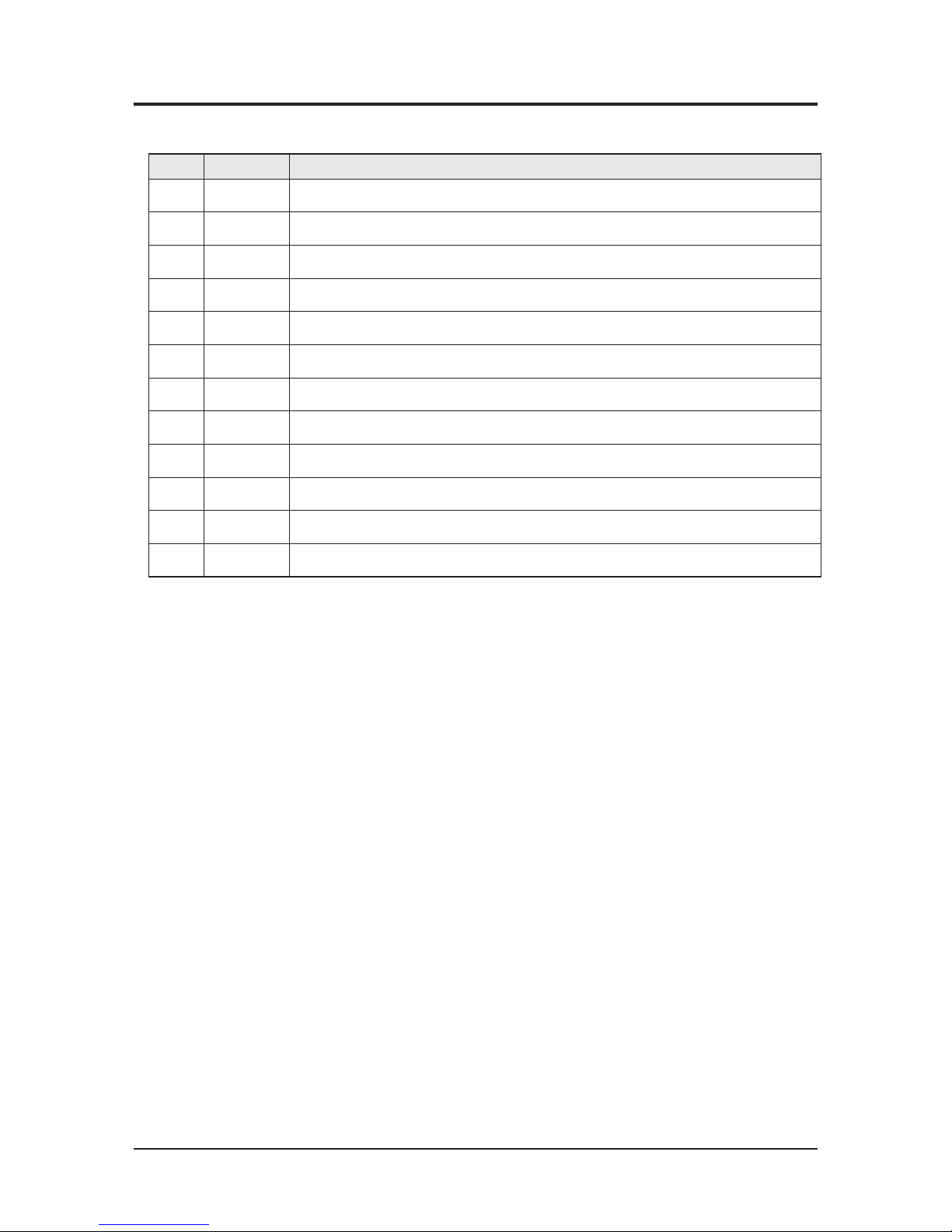
Q Error codes appear on display of wired remote control and unit body as follows.
No Error Mode Error code
1 E 108 Address setting duplication error
2 E121 Indoor temperature sensor error(SHORT/OPEN)
3 E139 CO sensor error(SHORT/OPEN)
4 E162 Indoor EEPROM H/W error
5 E163 Indoor option setting error
6 E198 Thermal fuse open error in power therminal block
7 E202 System down caused by communication error
8 E221 Outdoor temperature sensor error(SHORT/OPEN)
9 E490 Prohibition of operation under outside & indoor temperature 0 °
10 E561 Supply air(SA) fan motor error
11 E562 Exhaust air(EA) fan motor error
12 E654 Inside damper error
9-3 Errors and Solutions
6 602~609 indicate errors due to ERV wired remote control. Refer to the ERV wired remote control installation manual.
Page 64
Samsung Electronics 9-3
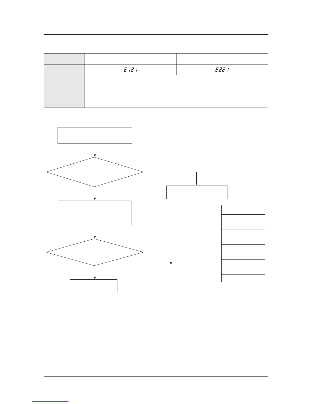
Error Mode Indoor temperature sensor error (OPEN/SHORT) Outdoor temperature sensor error (OPEN/SHORT)
Display
Check Method Temperature sensor disconnection or dislocation
Cause Connection electrodes contact, sensor disconnection or electric leakage
Sensor SPEC. 103 AT : 25˚C 10K
Outdoor temperature
thermistor disorder(replacement)
No
Yes
Yes
E121 (E221) code appears when unit operation
starts or while it is in operation.
Is temperature sensor connector (CN41)
of PCB dislocated from PCB?
Yes
Detach the temperature sensor connector
from PCB, to measure resistance between the
two electrodes.
Restart the unit after having
replaced PCB.
Is measured resistance
a lot different from the value
specified by the table besides?
Restart operation after link the
connector to PCB.
No
Temperature
(˚C)
Resistance
(k)
70 2.2
60 3.0
50 4.2
40 5.8
30 8.3
20 12.1
10 18.0
0 27.3
-10 43.0
9-4-1 Temperature Sensor Error(CN41)
9-4 Fault Diagnosis by Symptom
Page 65
9-4 Samsung Electronics
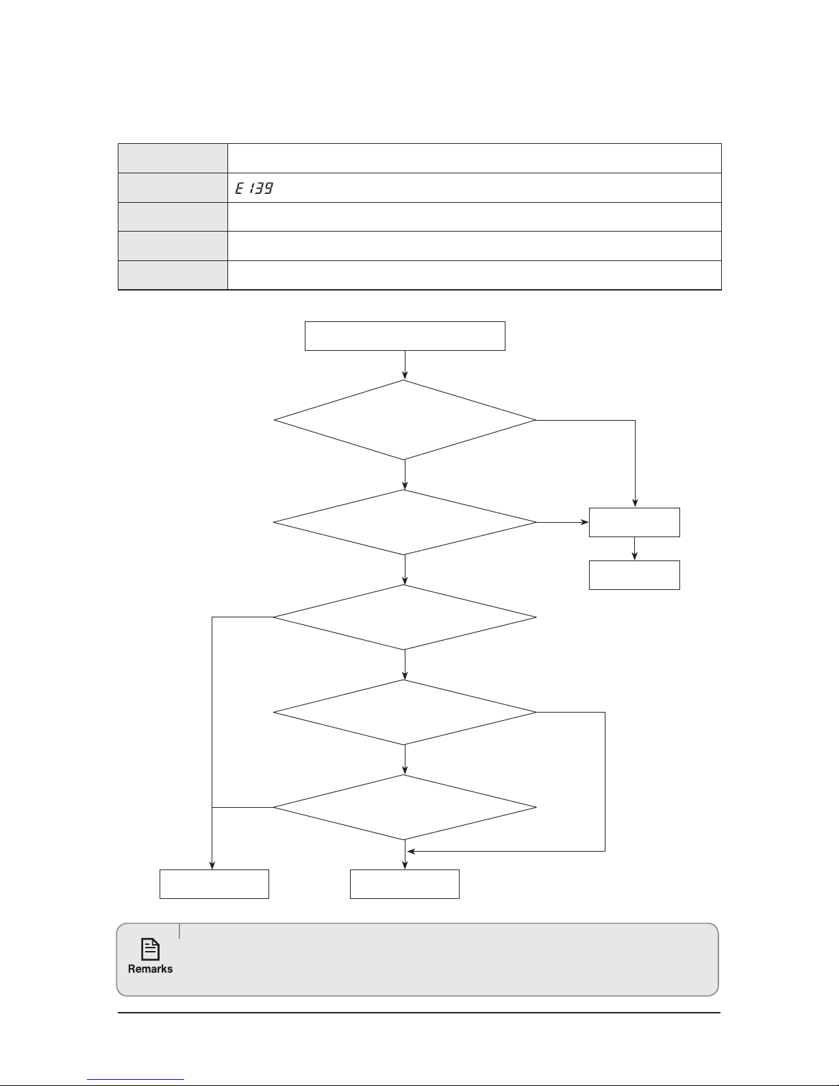
Error Mode CO2 sensor error (OPEN/SHORT)
Display
Check Method When CO
2 input pulse maintains High status or Low status for longer than 2 minutes.
Cause PCB check, CO
2 sensor check or replacement
Sensor SPEC. Preheating time in case of power supply authorization (2 minutes), Authorized power supply DC12V, 400~2,000PPM
9-4-2 CO2 Sensor Error(CN43)
Check product
operation.
Yes
Yes
Yes
E139 code appears when unit
operation starts or while it is in operation.
No
Is CO2 sensor connector (CN43)
of PCB dislocated from PCB?
Assembly the
connector
Yes
No
Is sensor connector CN101
dislocated from the sensor?
Does LED1 of CO2 sensor
flicker once in 6 seconds?
Is DC12V power measured
from sensor connector ①↔③?
Is square wave measured
from sensor connector ③↔②?
PCB check or replacement
Sensor check or
replacement
No
No
No
t$02 sensor checks DATA once in six seconds. It waits for 5 seconds and conducts data check for one second.
t$0
2 sensor and LED 1 light up for 1 second when the sensor check DATA.
t$02 Sensor checks DATA ranges 400PPM~2,000PPM.
t5IFQSPDFTTSFRVJSFTTFDPOEPGQSFIFBUJOHEVSJOHXIJDI%"5"DBODIBOHFT
Page 66
Samsung Electronics 9-5
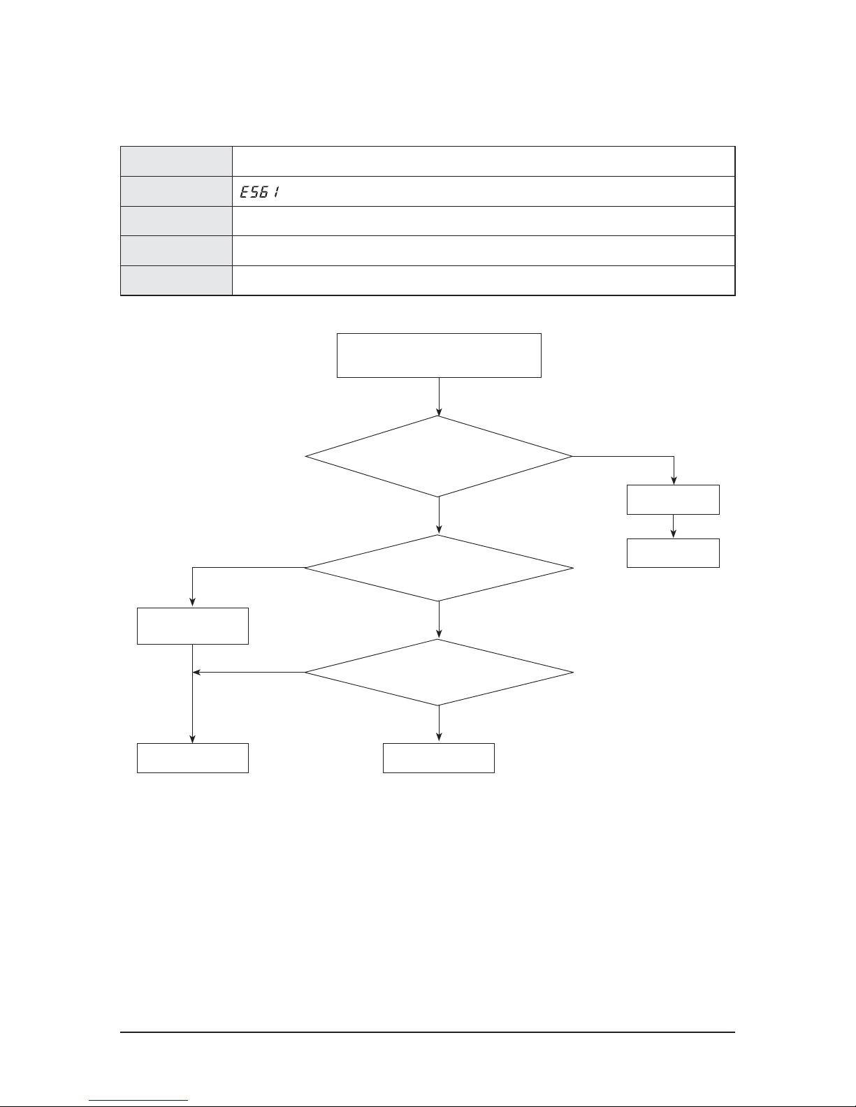
Error Mode Supply air fan error
Display
Check Method ERROR occurs, if Motor RPM is lower than 120 RPM for about 40 seconds.
Cause PCB check, Motor check
Sensor SPEC. Motor RPM outputs square wave.
9-4-3 Supply Air Fan Error
Check product
operation
No
Is Motor connector (CN74)
of PCB dislocated from PCB?
Assembly connector
Yes
No
Does Motor rotate in case of operation?
Is DC0V~DC6V power measured
from Motor ③↔⑤?
PCB check or replacement
Is Motor RPM is lower
than 120?
Yes
E561 code appears when
unit operation starts or while it is in operation.
No
Motor check or
replacement
Yes
Page 67
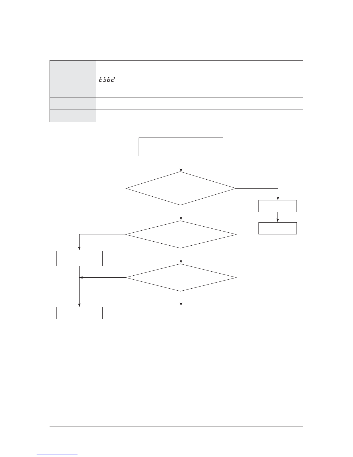
9-6 Samsung Electronics
Error Mode Exhaust Air Fan error
Display
Check Method ERROR occurs, if motor RPM is lower than 120 RPM for about 40 seconds.
Cause PCB check, Motor check
Sensor SPEC. Motor RPM outputs square wave.
9-4-4 Exhaust Air Fan Error
Check product
operation
No
Is Motor connector (CN73)
of PCB dislocated from PCB?
Assembly connector
Yes
No
Does Motor rotate in case of operation?
Is DC0V~DC6V power measured
from Motor ③↔⑤?
PCB check or replacement
Is Motor RPM is lower
than 120?
Yes
E562 code appears when
unit operation starts or while it is in operation.
No
Motor check or
replacement
Yes
Page 68
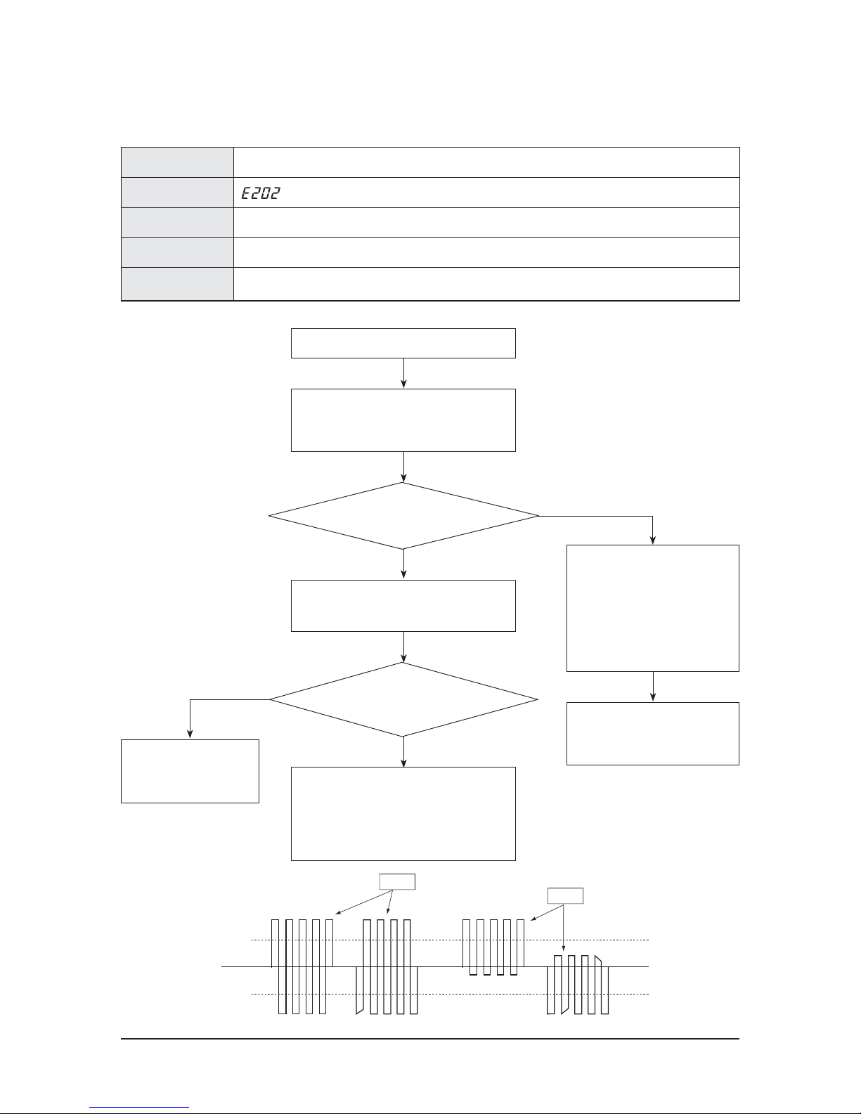
Samsung Electronics 9-7
Error Mode Communication error
Display
Check Method
MASTER ↔ SLAVE Communication failure continues for 2 minutes after Tracking is completed.
Cause OPTION setup, PCB check or replacement
Sensor SPEC. Communication, F1, F2
9-4-5 System Down Caused by Communication Error after Tracking
Yes
Check whether PCB address setup
is overlapped or not after having found
out SLAVE reporting error about
2 minutes later. (If PCB address setup
is overlapped, communication error
may occur.) In this case, both Slaves
with wrong address setup suffer from
communication error.
No
아니오
Does Tracking display show
no response at all from any Slave?
Check the communication
line of MASTER PCB and
connector, then, replace the PCB.
No
E202 code appears when unit
operation starts or while it is in operation.
Check display with pressing RESET KEY K3 of
MASTER PCB in order to CHECK number of Slaves
responding to Tracking.
After eliminate communication line
connecting Master and Slave, check the 2 lines
of Masterwith Scope.
Reconnect communication line between Mster
and Slave. Eliminate all communication connectors
on Slave PCB and connect them again one by one.
Find out the Slave interrupting communication
and check its lines. Then, replace Slave PCB.
If there is nothing wrong with address.
Check communication line and replace
Slave PCB.
Yes
Yes
+0.7V
-0.7V
Good
Bad
Is the voltage between the 2 lines
is square wave higher than DC±0.7V as
seen in the picture below?
Page 69
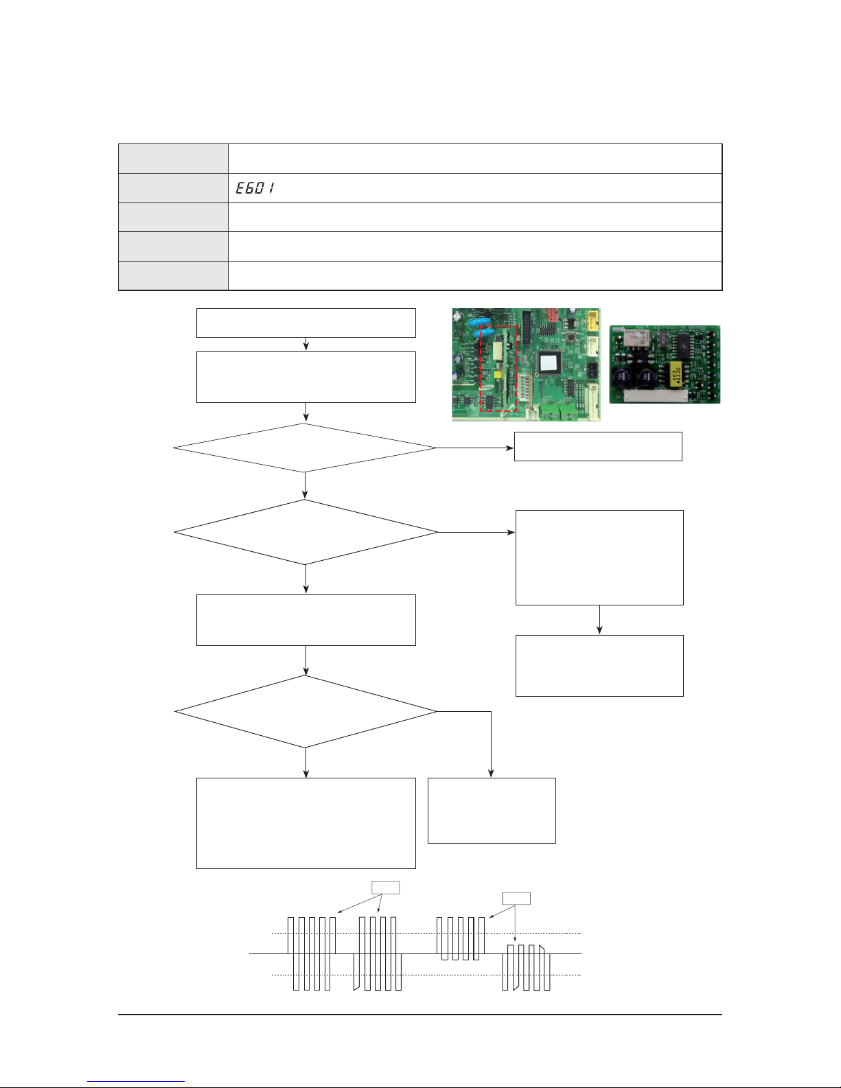
9-8 Samsung Electronics
Error Mode Communication error
Display
Check Method Communication between wired remote control and ventilator continues to fail for longer than two minutes.
Cause OPTION setup, PCB check or replacement
Sensor SPEC. Communication F3, F4
9-4-6 Wired Remote Control Communication Error
+0.7V
-0.7V
Good
Bad
Check number of ventilators
connected at the time of tracking.
Check the first SEGMENT of PCB display
of ventilators connected with wired
remote control, in order to find out
“U” flickers.
Check communication line and
connector of ventilator of
which “U” does not flicker.
Then replace PCB.
Yes
아니오
Number of ventilators connected
at the time of tracking is indicated?
Is voltage of the 2 lines square wave of over
DC±0.7V as seen in the picture below?
No
E601 code appears when unit operation
starts or while it is in operation.
Start retracking with pressing both Wind Strength
Control Button and Operation Selection Button of
Wired Remote Control simultaneously for 5 seconds.
Eliminate communication line between
Wired Cemote Control and Ventilator. Measure
2 lines of Wired Remote Control with SCOPE.
Reconnect communication line between wired
remote control and ventilator. Eliminate all
communication connectors on PCB and connect
them again one by one. Find out the ventilator
interrupting communication and check its lines.
Then, replace PCB.
Yes
Check wired remote control
PCB communication line and
connector and replace PCB.
No
SUB PBA Reassembly.
No
Check the correct connection of SUB PBA.
Yes
Page 70
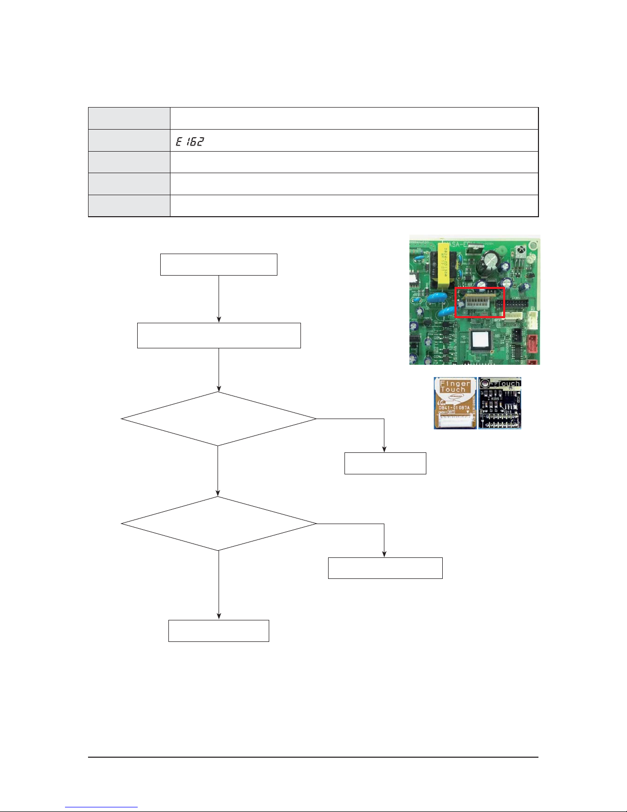
Samsung Electronics 9-9
Error Mode EEPROM Error
Display
Check Method Communication Failure between EEPROM and Micom
Cause Fault of EEPROM
Sensor SPEC.
9-4-7 EEPROM Error
EEPROM Reassembly
Remove short or unsoldering
Replace EEPROM PBA.
No
No
Yes
Yes
Is EEPROM SUB PBA reassembled correctly?
Is any problem such as short or unsoldering
between EEPROM PIN?
Turn on the unit.
Occurrence of E162
EEPROM PBA CODE
: DB93-12483A
Page 71
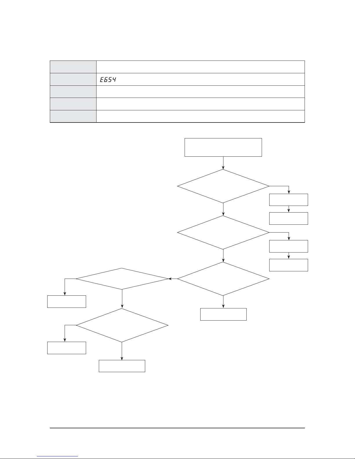
9-10 Samsung Electronics
9-4-8 DAMPER Error
Error Mode DAMPER Error
Display
Check Method Check error if there is no input in case of DAMPER output for 100 seconds (time required when it rotates 5 turns).
Cause PCB check, Motor check, Switch check
Sensor SPEC.
Switch check or
replacement
PCB check or
replacement
No
No
Yes
Yes
Check operation
Assembly the
connector
Yes
No
Check operation
No
Is DAMPER Motor connector of
PCB(CN72) dislocated from PCB?
Assembly the
connector
Yes
Is DAMPER switch working?
PCB check or replacement
E654 code appears when unit operation
starts or while it is in operation.
No
Is DAMPER switch connector
of PCB (CN51) dislocated from PCB?
Is AC220-240V power measured from
connector (CN72) ①↔③?
Is OPEN/SHORT signal working
at connector (CN51)?
PCB check or replacement
Yes
Page 72
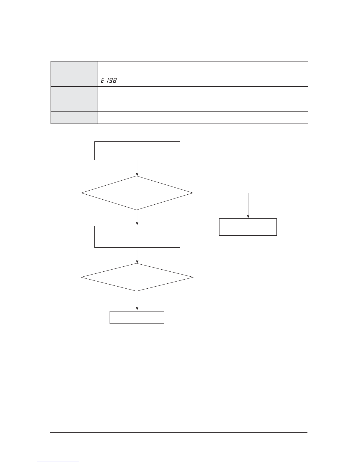
Samsung Electronics 9-11
Error Mode Thermal fuse open error in power therminal block
Display
Check Method Scanning the error when thermal fuse in power therminal block is opened
Cause Check the connection of terminal block(Temperature rise by screw loosening)
Sensor SPEC.
9-4-9 Thermal Fuse Open Error in Power Therminal Block
No
No
Is the CN140 Connector of PCB correctly
connected to wire?
Restart after connecting
connector.
Yes
Is the ends of the connector shorted?
Occurring E198.
Check both ends of the connector connected
terminal block.
Replace MAIN PBA.
No
Page 73
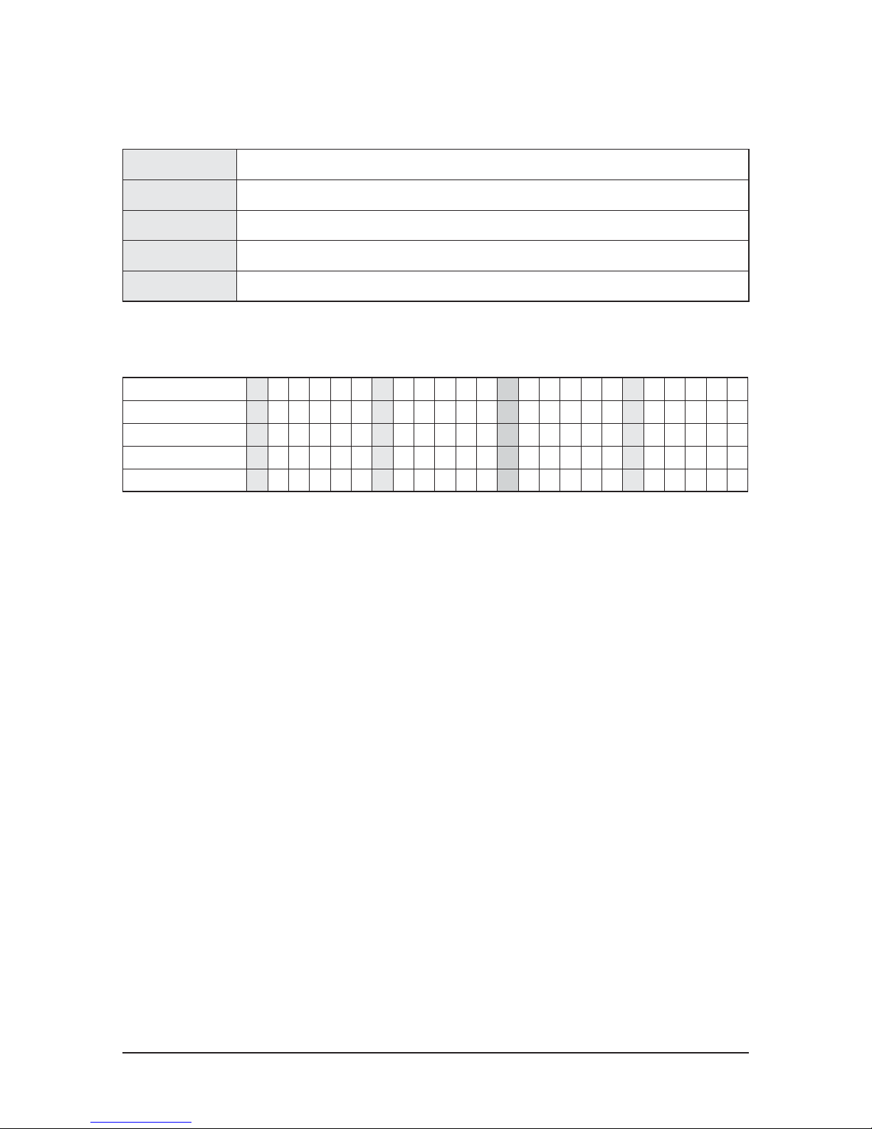
9-12 Samsung Electronics
AN026JSKLKN 0 1 0 3 4 0 1 1 6 4 4 4 2 1 4 4 4 0 3 0 2 0 0 3
AN035JSKLKN 0 1 0 3 4 0 1 1 4 4 3 4 2 1 3 4 3 0 3 0 2 0 0 5
AN050JSKLKN 0 1 0 3 4 0 1 1 6 4 4 4 2 1 5 4 4 0 3 0 2 0 0 6
AN080JSKLKN 0 1 0 3 4 0 1 1 5 4 4 2 2 1 4 4 4 0 3 0 2 0 0 7
AN100JSKLKN 0 1 0 3 4 0 1 1 6 4 4 3 2 1 5 4 4 0 3 0 2 0 0 8
Error Mode
Option setting error
Display
E163
Check Method
Entering incorrect ERV option or entering no ERV option at all
Cause
Entering incorrect ERV option or entering no ERV option at all
Sensor SPEC.
9-4-10 Option Setting Error
ఐProgress re-input after reconfirming option by model attached below.
If you use a existing EEPROM after replace MAIN PBA, don't need to reset option.
Page 74
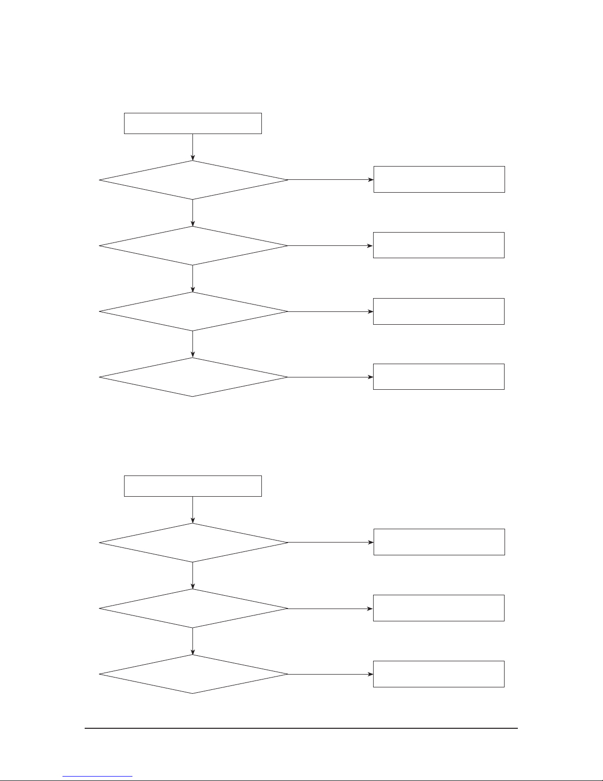
Samsung Electronics 9-13
9-4-11 When the unit stops infusing air
Clean or replace the filter if it contains too
much dust.
No
Yes
Is filter working properly?
Yes
Yes
Yes
The unit stops infusing air
Replace MOTOR
No
Is MOTOR working properly?
Clean or replace the filter if it contains too
much dust.
No
Is heat exchange element working properly?
Clean or replace the filter if it contains too
much dust.
No
Are outdoor air input and indoor
output in good conditions?
9-4-12 When indoor air smells bad or contains dust
Clean or replace the heat exchange element
if it is damaged.
No
Yes
Is heat exchange element working properly?
Yes
Yes
Indoor air smells bad or contains dust
Clean or replace the filter if it is damaged.
No
Is filter working properly?
Clean or replace the duct if it is damaged.
No
Is duct working properly?
Page 75
9-14 Samsung Electronics
9-4-13 When water drop is found in the Return Air duct or on ceiling
No
Yes
Is outside duct installed properly?
Yes
Yes
Yes
Is water drop found?
Install the duct properly.
(Duct slope 1/100 ~ 1/50)
Set the unit to Heat-EX mode in case of
heating with function switch.
No
Is the unit set to Heat-EX mode in case of heating?
Install the hood properly.
Replace it if it is damaged.
No
If there is no or fault insulation,
do the insulation job.
No
Is outside hood installed properly?
Is insulation of body and
duct done properly?
9-4-14 When cold air is infused
Control DAMPER (Change to Heat-EX mode)
No
Yes
DAMPER → Heat-EX mode ?
Yes
Is the unit infusing cold air?
Check heat exchange element and fix it.
No
Is heat exchange element
working properly?
Page 76
Samsung Electronics 9-15
9-4-15 When excessive noise is heard
Clean Filters.
No
Yes
Yes
Yes
Yes
Are Filter well cleaned?
Yes
Yes
Is the unit making excessive noise?
Install Heat Exchange Element and
filter properly.
Is there any substance inside the Duct?
Are Heat Exchange Element well cleaned?
No
Eliminate Dust or other substance.
No
Eliminate the substance.
No
Measure RPM and fix it.
No
Is Fan Motor working properly?
Replace or repair PCB.
Are Heat Exchange Element
and Filter installed properly?
Page 77
Samsung Electronics 10-1
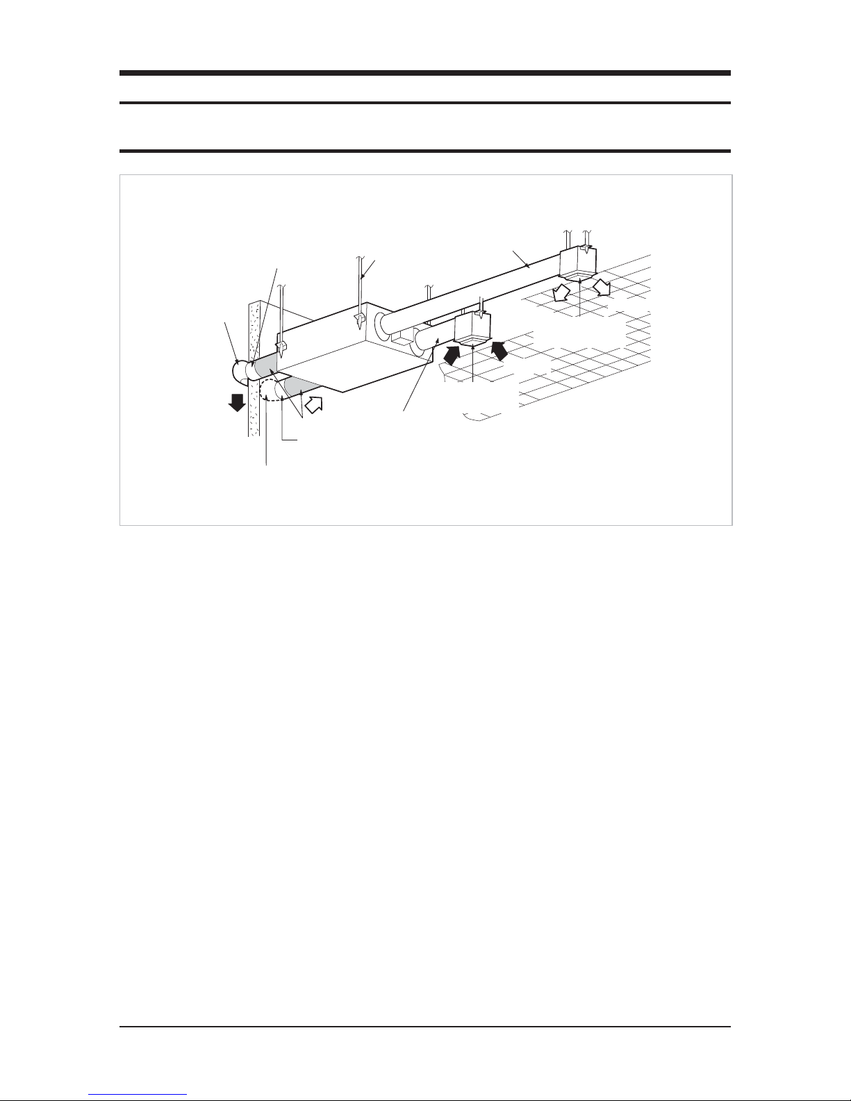
10. Reference Sheet
10-1 Ventilator Operation Principle
Exhaust duct
Exhaust Air
Anchor bolt
Supply Air duct
Return Air Duct
Hood
Outdoor Air suction duct
Insulation
Air intake hole
(Air exhaust grille)
Return
Air
Air discharging hole
(Air exhaust grille)
Supply Air
Hood
10-1-1 Operation Principle
Q Purpose : The ventilator aims at enhancing indoor air quality with utilizing fresh outdoor air. (At this section, only technological
explanation is provided.)
Q Process : The ventilator supplies outdoor air and exhaust indoor air.
Q Air Volume : The volume is determined according to volume of supply air or exhaust air. It is indicated with CMH
(Cubic Meter per Hour).
10-1-2 Additional Function
Q The unit supports Heat-EX mode and By-Pass mode (selected by DAMPER).
Q Heat-EX mode : Temperature and humidity of indoor air and outdoor air are exchanged
(The function minimizes heat loss from the process of ventilation).
Q By-Pass mode : Ventilation process without exchanging heat of indoor and outdoor air.
Page 78
10-2 Samsung Electronics
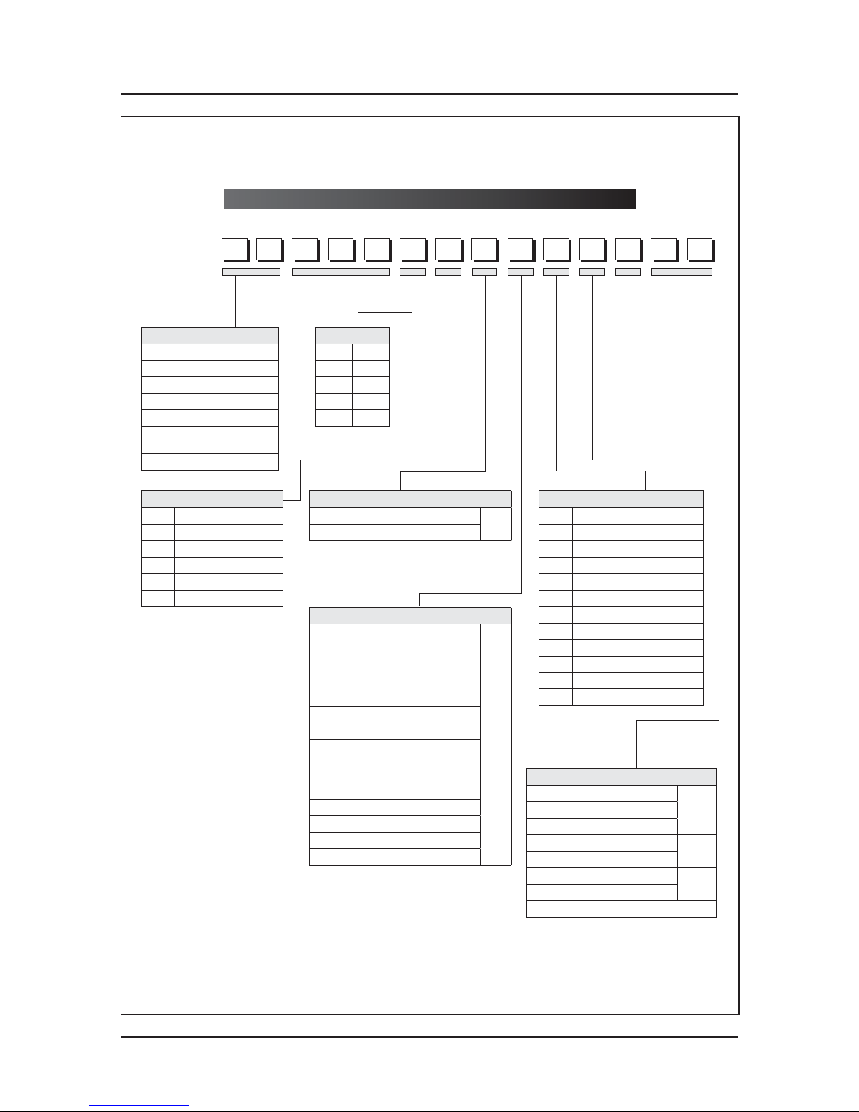
10-2 Index for Model Name
Model Code
※
"/" can be removed from the buyer card if there are not enough digits.
Product Type
AM DVM
AJ PMA
AC CAC (USD) / ASD
AE EHS
AN VTL
AK
PAK
(Packaged System)
AG CHR
Separator
S General Set (NASA)
N Indoor unit (NASA)
X Outdoor unit (NASA)
A General Set (Non-NASA)
B
Indoor unit (
Non-
NASA)
C
Outdoor unit (
Non-
NASA)
Separator
K
FLAT(CEILING TYPE)_VTL
VTL
S STAND(EXPOSURE TYPE)_VTL
Chassis Category
A
SLIM/HIGH VTL&FILTER
VTL
B SLIM/HIGH VTL
C SLIM/STANDARD
D NORMAL/HIGH VTL&FILTER
E NORMAL/HIGH VTL
F NORMAL/STANDARD
G MOLD/HIGH VTL&FILTER
H MOLD/HIGH VTL
J MOLD/STANDARD
K
COMMERICIAL/HIGH
VTL&FILTER
L COMMERICIAL/HIGH VTL
M COMMERICIAL/STANDARD
T MINI/HIGH VTL
V ERV with DX coil
Rating Voltage
A A(115V, 60hz, 1)
B B(220V, 60Hz, 1)
C C(208~230V, 60Hz)
D D(200~220V, 50Hz)
E E(220~240V, 50Hz)
F F(208~230V, 60Hz, 3)
G G(380~415V, 50Hz, 3)
H H(380V, 60Hz, 3)
J J(460V, 60Hz, 3)
K K(220~240V, 50/60Hz, 1)
M M(127V, 50Hz)
N N (380~415V, 50/60Hz, 3)
Year
E 2012
F 2013
G 2014
H 2015
J 2016
Buyer Name
Air Volume(CMH)
Mode
C
COOLING ONLY
R410a
H
HEAT PUMP
R
HEAT RECOVERY
D
COOLING ONLY
R22
E
HEAT PUMP
A
Cooling only
R134A
B
Heat Pump
N
N/A
HCH
1
H2H5H
J
H
N
H
4
H
C
H
E
H
H
H
/
H
E
H
U
H
A
Page 79
Samsung Electronics 10-3
Q AN026JSKLKN
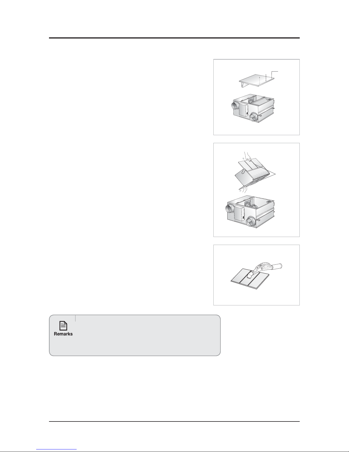
10-3 Cleaning the Dust Filter
1. Remove 3 screws on the maintenance cover.
2. Take off the maintenance cover from the ventilator.
3. Detach the dust filters by pulling them forward.
O
There are totally 2 dust filters on both sides of the heat exchange element.
4. Remove all dust on the dust filters with a vacuum cleaner or a brush.
5. Reassemble the dust filters and the maintenance cover.
O
Make sure to insert the dust filters correctly. If not, dust may accumulate on the
heat exchange element and decrease the efficiency.
t$IBOHFUIFEVTUGJMUFSTJOFWFSZUXPZFBST)PXFWFSUIFQFSJPEPGGJMUFS
replacement may vary according to the used period and condition.
t*GUIFEVTUGJMUFSJTEBNBHFEQVSDIBTFJUJOEJWJEVBMMZJOBTFSWJDFDFOUFS
or an agency that you bought the product.
t.BLFTVSFUPUVSOPGGUIFTVCQPXFSTVQQMZ
Dust filter
Screw
Page 80
10-4 Samsung Electronics
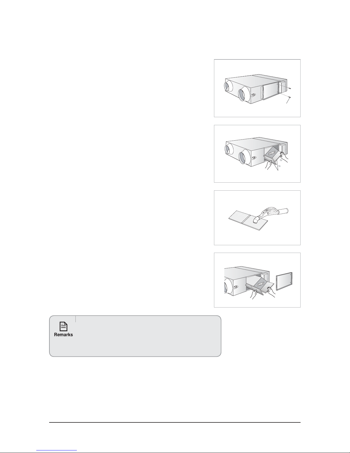
Q AN035JSKLKN/AN050JSKLKN/AN080JSKLKN/AN100JSKLKN
1. Remove 2 screws on the maintenance cover.
2. Take off the maintenance cover from the ventilator.
3. Detach the dust filters by pulling them forward.
O
There are totally 4 dust filters on both sides of the heat exchange element.
4. Remove all dust on the dust filters with a vacuum cleaner or a brush.
5. Reassemble the dust filters and the maintenance cover.
O
Make sure to insert the dust filters correctly. If not, dust may accumulate on the
heat exchange element and decrease the efficiency.
t$IBOHFUIFEVTUGJMUFSTJOFWFSZUXPZFBST)PXFWFSUIFQFSJPEPGGJMUFS
replacement may vary according to the used period and condition.
t*GUIFEVTUGJMUFSJTEBNBHFEQVSDIBTFJUJOEJWJEVBMMZJOBTFSWJDFDFOUFS
or an agency that you bought the product.
t.BLFTVSFUPUVSOPGGUIFTVCQPXFSTVQQMZ
Dust filter
Screw
Page 81
Samsung Electronics 10-5
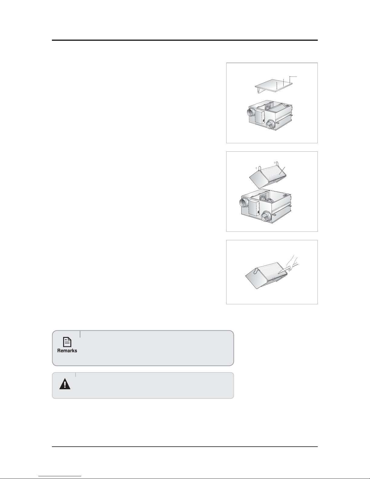
Q AN026JSKLKN
10-4 Cleaning the Heat Exchange Element
1. Remove 3 screws on the maintenance cover.
2. Take off the maintenance cover from the ventilator.
3. Detach the heat exchange element by pulling it upward.
O
The heat exchange element is heavy. Take care not to drop it.
4. Remove all dust and particles on the heat exchange element with a
nozzle of a vacuum cleaner.
O
Take care not to attach the nozzle too close.
It may damage the heat exchange element.
5. Reassemble the heat exchange element and the maintenance cover.
tDo not wash the heat exchange element. It may decrease its efficiency.
t*GUIFIFBUFYDIBOHFFMFNFOUJTEBNBHFEQVSDIBTFJUJOEJWJEVBMMZ
in a service center or an agency that you bought the product.
t.BLFTVSFUPUVSOPGGUIFTVCQPXFSTVQQMZ
Heat exchange
element
Screw
Page 82
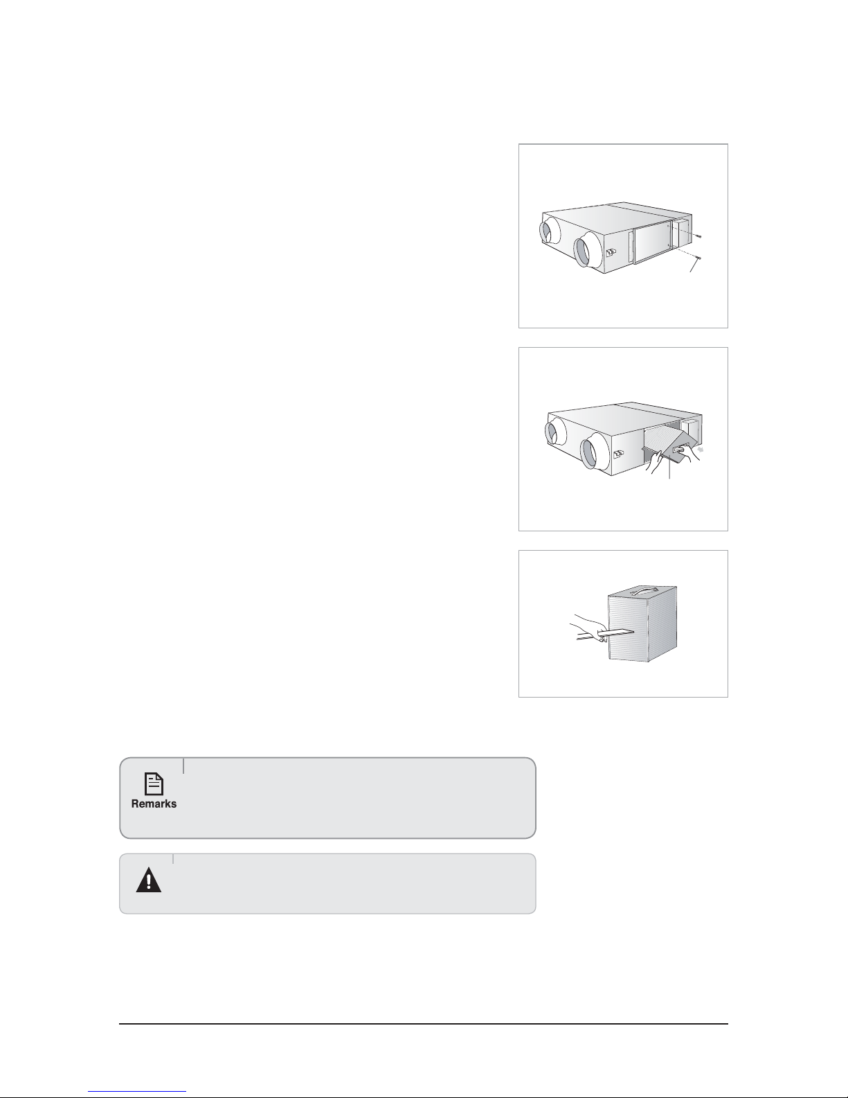
10-6 Samsung Electronics
Q AN035JSKLKN/AN050JSKLKN/AN080JSKLKN/AN100JSKLKN
1. Remove 2 screws on the maintenance cover.
2. Take off the maintenance cover from the ventilator.
3. Detach the 2 heat exchange elements in order.
O The heat exchange element is heavy. Take care not to drop it.
O There are 2 heat exchange elements in the ventilator.
Make sure clean them at once.
4. Remove all dust and particles on the heat exchange elements with a
nozzle of a vacuum cleaner.
O
Take care not to attach the nozzle too close.
It may damage the heat exchange element.
5. Reassemble the heat exchange elements and maintenance cover.
tDo not wash the heat exchange element. It may decrease its efficiency.
t*GUIFIFBUFYDIBOHFFMFNFOUJTEBNBHFEQVSDIBTFJUJOEJWJEVBMMZ
in a service center or an agency that you bought the product.
t.BLFTVSFUPUVSOPGGUIFTVCQPXFSTVQQMZ
Heat exchange element
Screw
Page 83
Samsung Electronics 10-7
10-5 Q & A for Non-trouble
Classification Class Description
Related to
ventilate
operation
Q Why is the ventilator required? (What is the difference between ventilator and air cleaner?)
A
- Definition : Ventilation is to supply fresh outdoor air to the inside of building and to exhaust indoor air.
(The measures include technological method and natural method.)
- Air cleaner cleans indoor air with system conta
ined in the unit. On the other hand, ventilation
enhances indoor air by replacing indoor air with outdoor air. They can be used according to the purpose
and conditions.
Q Has the effectiveness of ventilator been proved?
A
There is no scientific research to identify the effectiveness of
ventilation. However, it is well known that
opening windows can enhance indoor air quality. If windows open for a long period of time in summer
and winter, it may cause huge heat loss. Thereby, the ventilator is required.
Q Where are ventilators utilized?
A
Ventilator can be us
ed in all spaces within buildings except places with ventilation system such as
bathrooms or kitchens with hood.
Q How the functions can be exchanged?
A The unit supports manual and automatic operation which includes four function modes, according to air
volume. Heat-EX (required in summer and winter) a
nd usual ventilation (optional in spring and fall) are
available
Others
Q What is the function and composition of filter?
A - The unit is equipped with dust filter which protects heat exchange element and prevents dust from
flowing into the inside of building.
- D
eodorizing filters and functional filters are optional. (However, air volume can change due to resistance
blocking air flow of filter.)
Q Replacement period of the Heat exchange element and the filter?
A
Heat exchange element
- Cleaning method and period : clean the e
lement with vacuum cleaner (once in six months)
- Replacement period : If it is not damaged or modified, it can be used permanently because it is made
of paper.
Filter
- Dust filter (Standard) : Clean the element with vacuum clea
ner (once in 6 months)
3FQMBDFNFOUQFSJPEt0ODF JO ZFBST )PXFWFS UIF SFQMBDFNFOU GSFRVFODZ WBSJFT BDDPSEJOH UP
environment.)
t3FNPUFDPOUSPMTVQQPSUTGJMUFSSFQMBDFNFOUBMBSNGVODUJPO
Page 84
This Service Manual is a property of Samsung Electronics Co., Ltd.
Any unauthorized use of Manual can be punished under applicable
International and/or domestic law.
© Samsung Electronics Co., Ltd. April. 2015.
Printed in Korea.
Code No. AC-AC-00113E_1
GSPN (GLOBAL SERVICE PARTNER NETWORK)
Area Web Site
Europe, CIS, Mideast & Africa gspn1.samsungcsportal.com
Asia gspn2.samsungcsportal.com
North & Latin America gspn3.samsungcsportal.com
China china.samsungportal.com
 Loading...