

Page 1

User Manual
ED65E ED75E
EM65E EM75E
DC32E DC40E DC48E DC55E
DC32E-M DC40E-M DC48E-M DC55E-M
DC40E-H DC48E-H
The color and the appearance may differ depending on the product, and the
specifications are subject to change without prior notice to improve the performance.
Recommended hours of use per day for the EDE, EME, DCE models is less than 16 hours.
If the product is used for longer than 16 hours a day, the warranty may be void.
Page 2

Table of contents
Before Using the Product
Copyright 6
Safety Precautions 7
Symbols 7
Cleaning 7
Storage 8
Electricity and Safety 8
Installation 9
Operation 11
Preparations
Checking the Components 15
Components 15
Parts 16
Control Panel 16
Reverse Side 18
Reverse Side 19
Anti-theft Lock 20
Remote Control 21
Before Installing the Product
(Installation Guide) 23
Switching between portrait and landscape 23
Ventilation 23
Installing the Wall Mount 24
Preparing before installing Wall-Mount 24
Installing the Wall Mount Kit 24
Wall Mount Kit Specifications (VESA) 25
Remote Control (RS232C) 26
Cable Connection 26
Connection 29
Control Codes 30
Connecting and Using a Source
Device
Before Connecting 39
Pre-connection Checkpoints 39
Connecting to a PC 39
Connection using the D-SUB cable
(Analog type) 39
Connection using a DVI cable (Digital type) 40
Connection Using an HDMI-DVI Cable 40
Connection Using an HDMI Cable 41
Connecting to a Video Device 42
Connection Using the AV Cable 42
Connection Using the component Cable 42
Connection Using an HDMI-DVI Cable 43
Connection Using an HDMI Cable 44
Connecting to an Audio System 44
Connecting the Antenna 45
Connecting the LAN Cable 45
Connecting the HDBase-T 46
Changing the Input source 47
Source 47
Using MDC
MDC Program Installation/Uninstallation 48
Installation 48
Uninstallation 48
Connecting to MDC 49
Using MDC via RS-232C
(serial data communications standards) 49
Using MDC via Ethernet 50
Screen Adjustment
Picture Mode 51
If the input source is PC, DVI, HDMI(PC) 51
If the input source is TV, AV, Component,
HDMI(AV
Backlight / Contrast / Brightness / Sharpness /
Color / Tint (G/R)
Gamma 52
Calibrated Value 53
Picture Size 54
Picture Size 54
Position 55
Zoom/Position 55
Resolution Select 56
Auto Adjustment 56
PC Screen Adjustment 57
) 51
52
2
Page 3

Table of contents
PIP 58
Advanced Settings 59
Dynamic Contrast 60
Black Tone 60
Flesh Tone 60
RGB Only Mode 60
Color Space 60
White Balance 60
Motion Lighting 60
Picture Options 61
Color Tone 62
Color Temp. 62
Digital Clean View 62
MPEG Noise Filter 62
HDMI Black Level 63
Film Mode 63
Auto Motion Plus 63
Dynamic Backlight 63
Picture Off 64
Reset Picture 64
Sound Adjustment
Broadcasting
Auto Program 68
Antenna 69
Channel List 70
Mode 70
Guide 71
Schedule Manager 71
Edit Channel 72
Edit Favorites 74
Channel Settings 77
Fine Tune 77
Clear Scrambled Channel 77
Audio Options 78
Preferred Language 78
Multi-Track Sound 78
Visual Impaired 78
Program Rating Lock 79
Caption 81
Caption 81
Network
Network Status 83
Network Settings 83
Network type 83
Network Settings (Wired) 84
Network Setting (Wireless) 86
WPS(PBC) 88
Wi-Fi Direct 89
AllShare Settings 89
Server Network Settings 90
Connect to Server 90
Server Access 90
FTP Mode 90
Device Name 90
Applications
Source List 91
Refresh 91
Edit Name 91
Information 91
Sound Mode 65
Sound Effect 66
Speaker Settings 67
Reset Sound 67
MagicInfo Lite 92
Playing content from the internal memory or
USB 92
Network Channel 93
3
Page 4

Table of contents
System
Setup 95
Menu Language 96
Multi Control 96
Configuring settings for Multi Control 96
Time 97
Clock 97
Sleep Timer 98
On Timer 98
Off Timer 99
Holiday Management 99
Eco Solution 100
Energy Saving 100
Eco Sensor 100
No Signal Power Off 100
Auto Power Off 100
Auto Protection Time 101
Screen Burn Protection 102
Pixel Shift 102
Timer 103
Immediate Display 104
Side Gray 104
Ticker 105
Video Wall 106
Video Wall 106
Format 106
Horizontal 106
Vertical 107
Screen Position 107
Source AutoSwitch Settings 108
Source AutoSwitch 108
Primary Source Recovery 108
Primary Source 108
Secondary Source 108
Change PIN 109
General 110
Max. Power Saving 110
Game Mode 110
Auto Power On 110
Safety Lock 110
Button Lock 111
Standby Control 111
HDBT Standby 111
Network Standby 111
Lamp Schedule 112
OSD Display 112
Power On Adjustment 112
Temperature Control 112
Anynet+ (HDMI-CEC) 113
Anynet+ (HDMI-CEC) 113
Auto Turn Off 114
Troubleshooting for Anynet+ 115
Clone Product 117
Reset System 117
Reset All 118
DivX® Video On Demand 118
PC Module Power 118
Synced Power-On 118
Synced Power-Off 118
Support
Software Update 119
Update now 119
Contact Samsung 119
Playing photos, videos and music
(Media Play)
Read the following before using media play
with a USB device 120
Using a USB device 122
Menu items in the media content list page 123
Available buttons and features during photo
playback 124
Available buttons and features during video
playback 125
Available buttons and features during music
playback 126
Supported Subtitle and Media play file
formats 127
4
Page 5

Table of contents
Subtitle 127
Compatible image file format 127
Supported music file formats 128
Supported Video Formats 128
Troubleshooting Guide
Requirements Before Contacting Samsung
Customer Service Center 131
Testing the Product 131
Checking the Resolution and Frequency 131
Check the followings. 132
Q & A 139
Specifications
General 140
Preset Timing Modes 142
Optimum Picture Quality and Afterimage
Burn-in Prevention 145
Optimum Picture Quality 145
Prevention of Afterimage Burn-in 145
License 147
Terminology 148
Appendix
Responsibility for the Pay Service
(Cost to Customers) 144
Not a product defect 144
A Product damage caused by customer's fault 144
Others 144
5
Page 6

Chapter 01
Before Using the Product
Copyright
The contents of this manual are subject to change without notice to improve quality.
© 2016 Samsung Electronics
Samsung Electronics owns the copyright for this manual.
Use or reproduction of this manual in parts or entirety without the authorization of Samsung Electronics is prohibited.
Microsoft, Windows are registered trademarks of Microsoft Corporation.
VESA, DPM and DDC are registered trademarks of the Video Electronics Standards Association.
Ownership of all other trademarks is attributed to their due owner.
6
Page 7
Safety Precautions
!
Caution
RISK OF ELECTRIC SHOCK DO NOT OPEN
Caution : TO REDUCE THE RISK OF ELECTRIC SHOCK, DO NOT REMOVE COVER. (OR BACK)
THERE ARE NO USER SERVICEABLE PARTS INSIDE.
REFER ALL SERVICING TO QUALIFIED PERSONNEL.
This symbol indicates that high voltage is present inside.
It is dangerous to make any kind of contact with any internal part of this product.
This symbol alerts you that important literature concerning operation and maintenance has been
included with this product.
Symbols
Cleaning
―
Exercise care when cleaning as the panel and exterior of advanced LCDs are easily scratched.
―
Take the following steps when cleaning.
―
The following images are for reference only. Real-life situations may differ from what is shown in the
images.
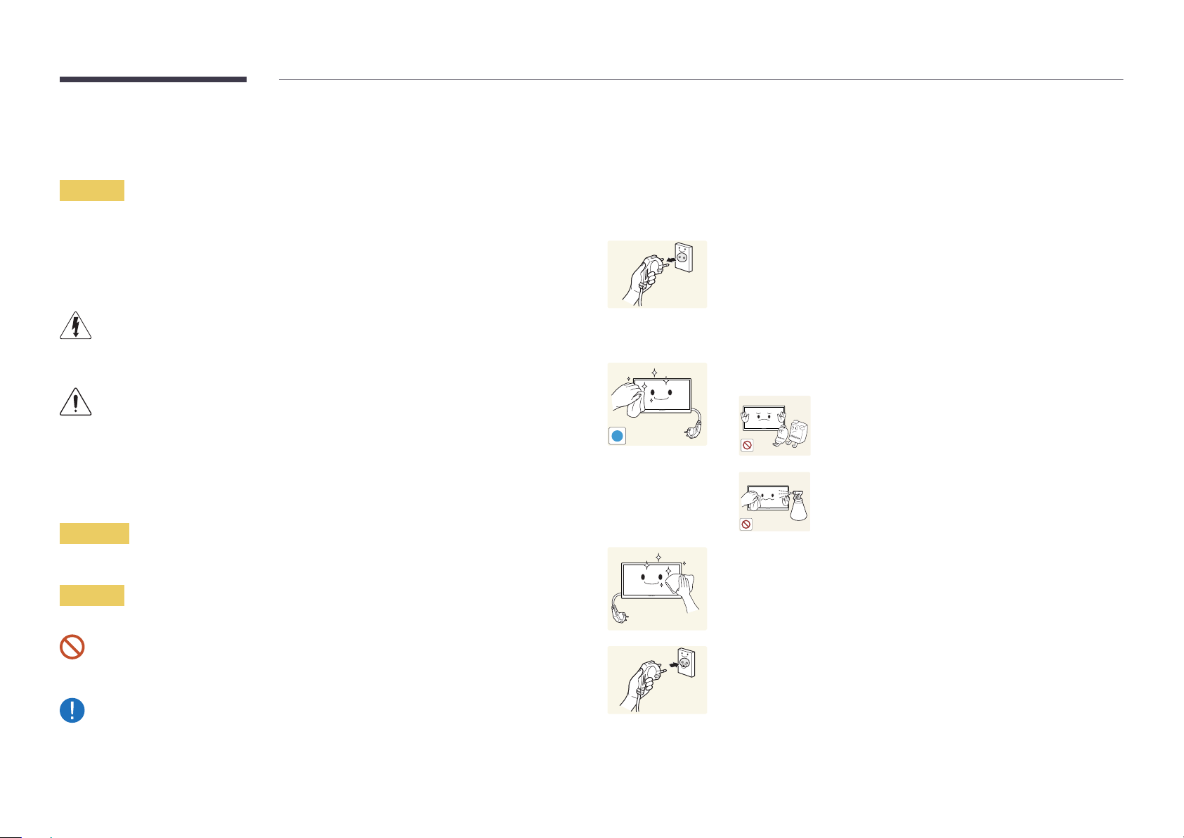
Power off the product and computer.
1
Disconnect the power cord from the product.
2
―
Hold the power cable by the plug and do not touch the cable with wet
hands. Otherwise, an electric shock may result.
Wipe the product with a clean, soft and dry cloth.
3
•
Do not use detergents that contain alcohol, solvent or
surface-active agents.
•
Do not spray water or detergent directly on the product.
Warning
Wet a soft and dry cloth in water and wring thoroughly to clean the
A serious or fatal injury may result if instructions are not followed.
4
exterior of the product.
Caution
Personal injury or damage to properties may result if instructions are not followed.
Connect the power cord to the product when cleaning is finished.
Activities marked by this symbol are prohibited.
Instructions marked by this symbol must be followed.
5
Power on the product and computer.
6
7
Page 8
Storage
Due to the characteristics of high-glossy products, using a UV humidifier nearby may create whitecolored stains on the product.
―
Contact Customer Service Center if the inside of the product needs cleaning (service fee will be
charged).
Electricity and Safety
―
The following images are for reference only. Real-life situations may differ from what is shown in the
images.
Warning
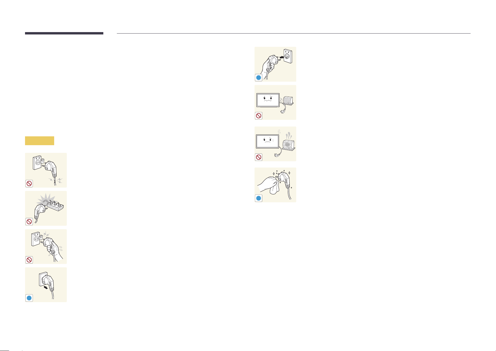
Do not use a damaged power cord or plug, or a loose power socket.
•
An electric shock or fire may result.
Do not use multiple products with a single power socket.
•
Overheated power sockets may cause a fire.
Connect the power plug to a grounded power socket (type 1 insulated
devices only).
•
An electric shock or injury may result.
!
Do not bend or pull the power cord with force. Be careful not to leave the
power cord under a heavy object.
•
Damage to the cord may result in a fire or electric shock.
Do not place the power cord or product near heat sources.
•
A fire or electric shock may result.
Clean any dust around the pins of the power plug or the power socket with
a dry cloth.
•
A fire may result.
!
Do not touch the power plug with wet hands. Otherwise, an electric shock
may result.
Insert the power plug all the way in so it is not loose.
•
An unsecure connection may cause a fire.
!
8
Page 9
Caution
!
!
!
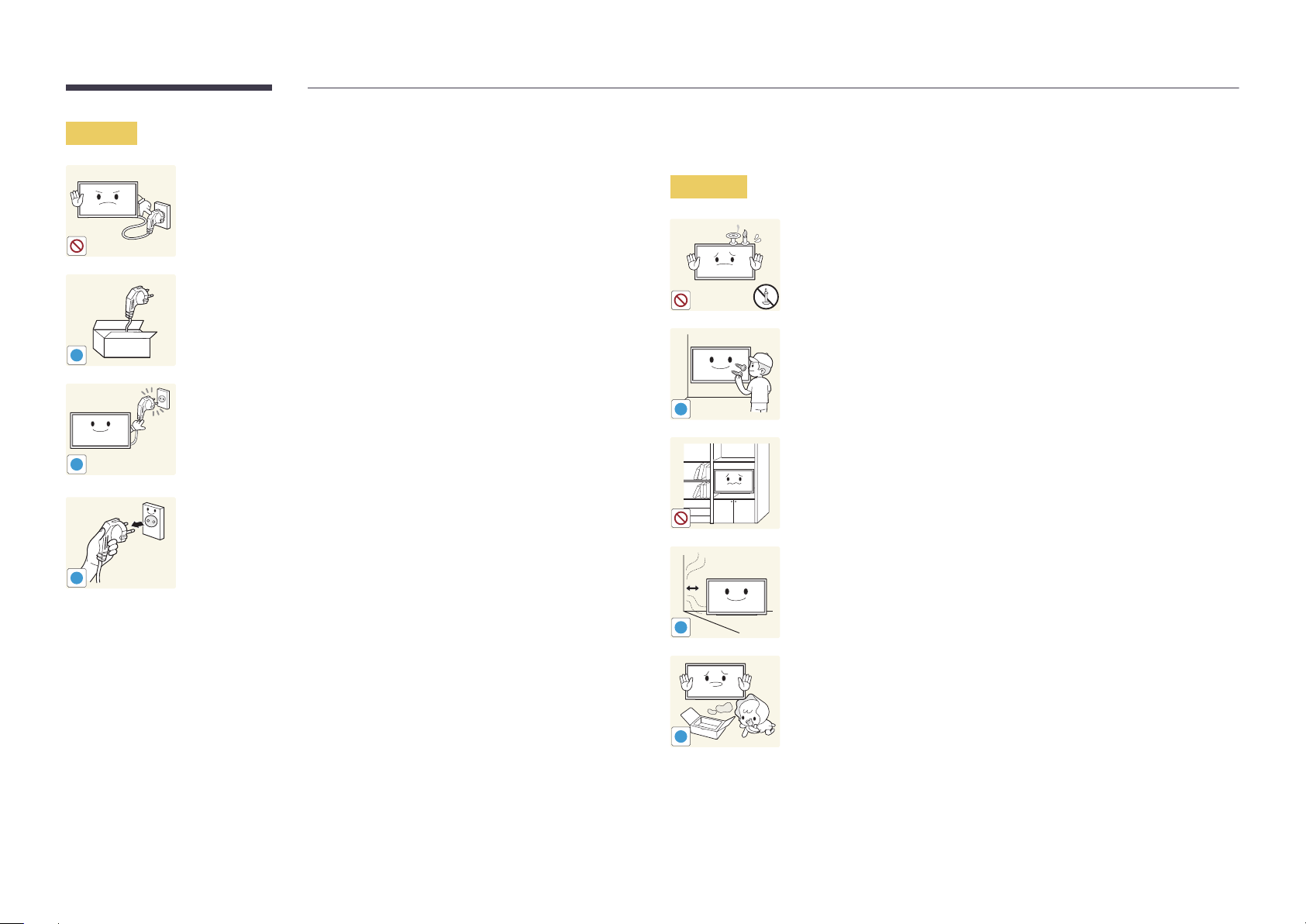
Do not disconnect the power cord while the product is being used.
•
The product may become damaged by an electric shock.
Only use the power cord provided with your product by Samsung. Do not
use the power cord with other products.
•
A fire or electric shock may result.
Keep the power socket where the power cord is connected unobstructed.
•
The power cord must be disconnected to cut off power to the product
when an issue occurs.
•
Note that the product is not completely powered down by using only
the power button on the remote.
Hold the plug when disconnecting the power cord from the power socket.
•
An electric shock or fire may result.
Installation
Warning
!
DO NOT PLACE CANDLES, INSECT REPELLANTS OR CIGARETTES ON TOP OF
THE PRODUCT. DO NOT INSTALL THE PRODUCT NEAR HEAT SOURCES.
•
A fire may result.
Have a technician install the wall-mount hanger.
•
Installation by an unqualified person can result in an injury.
•
Only use approved cabinets.
Do not install the product in poorly ventilated spaces such as a bookcase or
closet.
•
An increased internal temperature may cause a fire.
Install the product at least 10cm away from the wall to allow ventilation.
•
An increased internal temperature may cause a fire.
!
Keep the plastic packaging out of the reach of children.
•
Children may suffocate.
!
9
Page 10
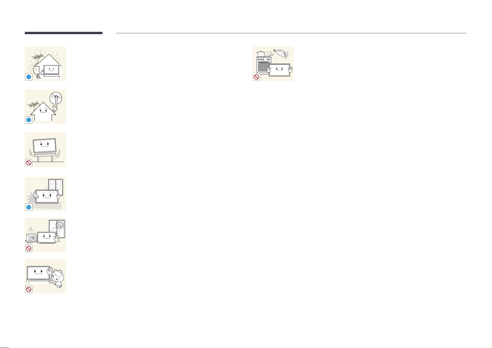
Bend and keep part of the outdoor TV antenna cable hanging downwards
(the part inside the room) to prevent rainwater from entering the product.
•
If rainwater enters the product, a fire or electric shock can occur.
!
When using an outdoor antenna, be sure to install the antenna away from
nearby power lines to prevent the antenna from collapsing onto them in
strong winds.
•
!
!
A collapsed antenna can cause an electric shock or injury.
Do not install the product on an unstable or vibrating surface (insecure shelf,
sloped surface, etc.)
•
The product may fall and become damaged and/or cause an injury.
•
Using the product in an area with excess vibration may damage the
product or cause a fire.
Do not install the product in a vehicle or a place exposed to dust, moisture
(water drips, etc.), oil, or smoke.
•
A fire or electric shock may result.
Edible oil, such as soybean oil, can damage or deform the product. Do not
install the product in a kitchen or near a kitchen counter.
Do not expose the product to direct sunlight, heat, or a hot object such as a
stove.
•
The product lifespan may be reduced or a fire may result.
Do not install the product within the reach of young children.
•
The product may fall and injure children.
•
As the front is heavy, install the product on a flat and stable surface.
10
Page 11
Caution
!
!
Do not drop the product while moving.
•
Product failure or personal injury may result.
Do not set down the product on its front.
•
The screen may become damaged.
When installing the product on a cabinet or shelf, make sure that the
bottom edge of the front of the product is not protruding.
•
The product may fall and become damaged and/or cause an injury.
•
Install the product only on cabinets or shelves of the right size.
Set down the product gently.
•
Product failure or personal injury may result.
Operation
Warning
!
!
There is a high voltage inside the product. Never disassemble, repair or
modify the product yourself.
•
A fire or electric shock may result.
•
Contact Samsung Customer Service Center for repairs.
Before moving the product, turn off the power switch and disconnect the
power cord, antenna cable and all other connected cables.
•
Damage to the cord may result in a fire or electric shock.
If the product generates abnormal sounds, a burning smell or smoke,
disconnect the power cord immediately and contact Samsung Customer
Service Center.
•
An electric shock or fire may result.
Do not let children hang from the product or climb on top of it.
•
Children may become injured or seriously harmed.
Installing the product in an unusual place (a place exposed to a lot of fine
dust, chemical substances, extreme temperatures or a significant presence
SAMSUNG
!
of moisture, or a place where the product will operate continuously for an
extended period of time) may seriously affect its performance.
•
Be sure to consult Samsung Customer Service Center if you want to
install the product at such a place.
If the product is dropped or the outer case is damaged, turn off the power
switch and disconnect the power cord. Then contact Samsung Customer
Service Center.
•
Continued use can result in a fire or electric shock.
11
Page 12
Do not leave heavy objects or items that children like (toys, sweets, etc.) on
top of the product.
•
The product or heavy objects may fall as children try to reach for the
toys or sweets resulting in a serious injury.
Do not use or keep combustible spray or an inflammable substance near
the product.
•
An explosion or fire may result.
!
During a lightning or thunderstorm, remove the power cable and do not
touch the antenna cable.
•
A fire or electric shock may result.
!
Do not drop objects on the product or apply impact.
•
A fire or electric shock may result.
!
100
Ensure the vents are not blocked by tablecloths or curtains.
•
An increased internal temperature may cause a fire.
Do not insert metallic objects (chopsticks, coins, hairpins, etc) or objects
that burn easily (paper, matches, etc) into the product (via the vent or input/
output ports, etc).
•
Be sure to power off the product and disconnect the power cord
when water or other foreign substances have entered the product.
Then contact Samsung Customer Service Center.
Do not move the product by pulling the power cord or any cable.
•
Product failure, an electric shock or fire may result from a damaged
cable.
•
Product failure, an electric shock or fire may result.
Do not place objects containing liquid (vases, pots, bottles, etc) or metallic
objects on top of the product.
•
Be sure to power off the product and disconnect the power cord
If a gas leakage is found, do not touch the product or power plug. Also,
ventilate the area immediately.
•
Sparks can cause an explosion or fire.
!
GAS
when water or other foreign substances have entered the product.
Then contact Samsung Customer Service Center.
•
Product failure, an electric shock or fire may result.
Do not lift or move the product by pulling the power cord or any cable.
•
Product failure, an electric shock or fire may result from a damaged
cable.
12
Page 13
Caution
!
-_-
!
Leaving the screen fixed on a stationary image for an extended period of
time may cause afterimage burn-in or defective pixels.
•
Activate power-saving mode or a moving-picture screen saver if you
will not be using the product for an extended period of time.
Disconnect the power cord from the power socket if you do not plan on
using the product for an extended period of time (vacation, etc).
•
Dust accumulation combined with heat can cause a fire, electric shock
or electric leakage.
Use the product at the recommended resolution and frequency.
•
Your eyesight may deteriorate.
Rest your eyes for more than 5 minutes for every 1 hour of product use.
•
Eye fatigue will be relieved.
!
Do not touch the screen when the product has been turned on for an
extended period of time as it will become hot.
Store small accessories out of the reach of children.
!
!
Do not hold the product upside-down or move it by holding the stand.
•
The product may fall and become damaged or cause an injury.
Looking at the screen too close for an extended period of time can
deteriorate your eyesight.
!
Do not use humidifiers or stoves around the product.
•
A fire or electric shock may result.
!
Exercise caution when adjusting the product angle or stand height.
•
Your hand or finger may get stuck and injured.
•
Tilting the product at an excessive angle may cause the product to fall
and an injury may result.
Do not place heavy objects on the product.
•
Product failure or personal injury may result.
When using headphones or earphones, do not turn the volume too high.
•
Having the sound too loud may damage your hearing.
13
Page 14
Be careful that children do not place the battery in their mouths when
removed from the remote control. Place the battery in a location that
children or infants cannot reach.
•
If children have had the battery in their mouths, consult your doctor
immediately.
When replacing the battery, insert it with the right polarity (+, -).
•
Otherwise, the battery may become damaged or it may cause fire,
personal injury or damage due to leakage of the internal liquid.
Use only the specified standardized batteries, and do not use a new battery
and a used battery at the same time.
•
Otherwise, the batteries may be damaged or cause fire, personal injury
!
!
or damage due to a leakage of the internal liquid.
The batteries (and rechargeable batteries) are not ordinary refuse and must
be returned for recycling purposes. The customer is responsible for returning
the used or rechargeable batteries for recycling.
•
The customer can return used or rechargeable batteries to a nearby
public recycling center or to a store selling the same type of the
battery or rechargeable battery.
14
Page 15
Chapter 02
Preparations
Checking the Components
-
Contact the vendor where you
purchased the product if any
components are missing.
-
The pictures may look different from the
actual components.
-
A stand is not provided with the product.
To install a stand, you can purchase one
separately.
-
The RS232C adapter can be used to
connect to another monitor using the
D-SUB (9-pin) type RS232C cable.
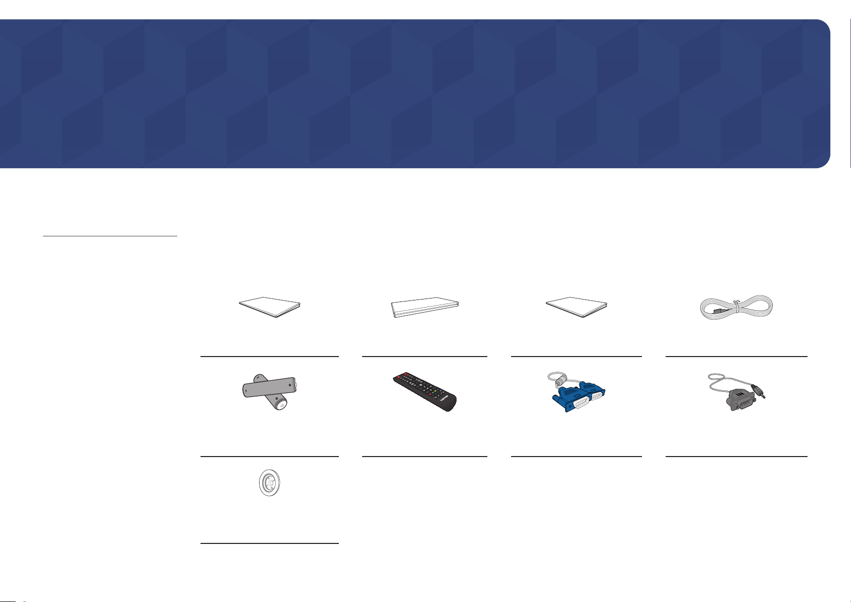
Components
―
Components may differ in different locations.
Quick Setup Guide
-
-
Batteries
(Not available in some locations)
Holder-Ring (4EA)
(EDE and EME Model Only)
+
+
Warranty card
(Not available in some locations)
Remote Control
Regulatory guide Power cord
D-SUB cable
(EDE and EME Model Only)
RS232C(IN) adapter
15
Page 16
Parts
―
The color and shape of parts may differ from what is shown. Specifications are subject to change without notice to improve
quality.
Buttons Description
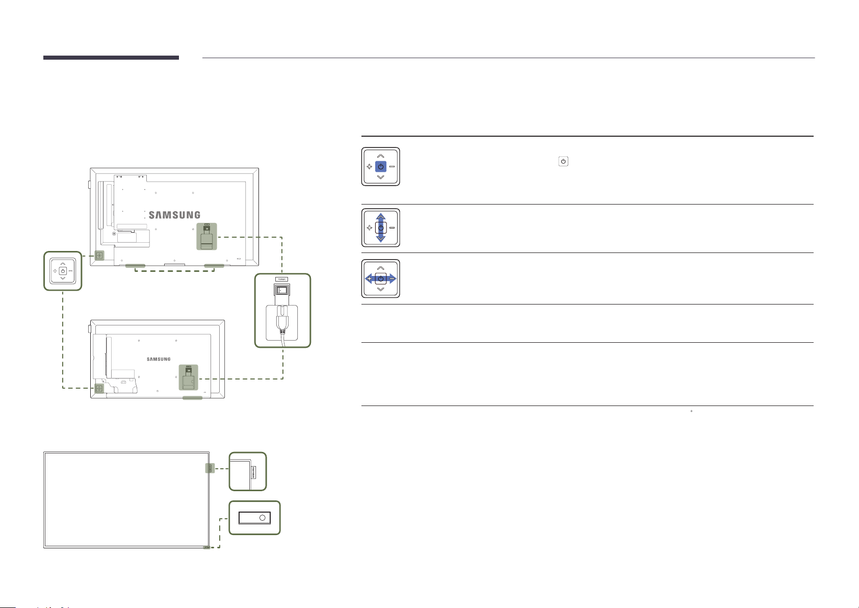
Control Panel
Panel Key
DC32E DC32E-M
Speaker
Speaker
Spacer logo
Power on the product.
If you press the button when the product is turned on, the control menu will be
displayed.
―
To exit the OSD menu, press and hold the panel key for at least one second.
Move to the upper or lower menu. You can also adjust the value of an option.
―
Change the channel in TV mode.
Move to the left or right menu.
―
You can adjust the volume by moving the panel key left or right when the control
menu is not displayed.
Spacer logo
(Optional)
Remote sensor
Use the remote control within 7 m to 10 m from the sensor on the product at an angle of 30
―
Store used batteries out of reach of children and recycle.
―
Do not use a new and used battery together. Replace both batteries at the same time.
―
Remove batteries when the remote control is not to be used for an extended period of time.
Do not pull on the spacer logo using force. The logo may tear or break off.
Press a button on the remote control pointing at the sensor on the front of the
product to perform the corresponding function.
―
Using other display devices in the same space as the remote control of this
product can cause the other display devices to be inadvertently controlled.
from the left and right.
Remote sensor
16
Page 17
―
If you press the
control menu will be displayed.
button on the panel key when the product is turned on, the
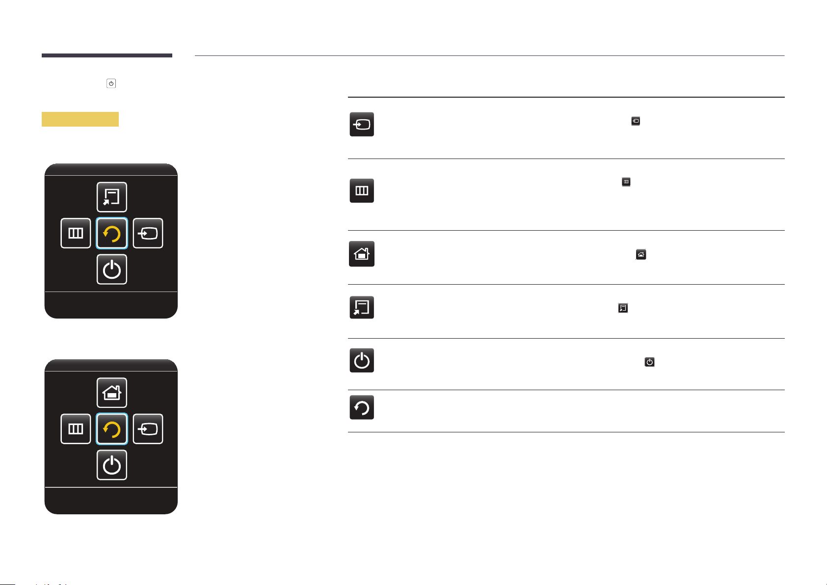
Control menu
EDE / EME
Return
Buttons Description
Select the connected input source.
Source
Menu
MagicInfo
Tools
Move the panel key right to select Source
input sources is displayed, move the panel key left or right to select the desired input
source. Next, press the panel key.
Display the OSD menu.
Move the panel key left to select Menu
screen will appear. Move the panel key right to select the desired menu. You can
select a sub-menu item by moving the panel key up, down, left, or right. To change
settings, select the desired menu and press the panel key.
Enter MagicInfo mode.
Move the panel key up to select MagicInfo
―
DCE, DCE-M, DCE-H models are only supported.
Display Tools.
Move the panel key up to select Tools
―
EDE, EME models are only supported.
in the control menu. When the list of
in the control menu. The OSD control
in the control menu.
in the control menu.
DCE / DCE-M / DCE-H
Return
Power O
Return
Power off the product.
Move the panel key down to select
the panel key.
Exit the control menu.
Power O
in the control menu. Next, press
17
Page 18
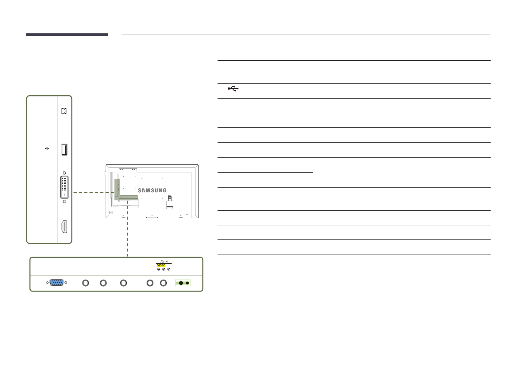
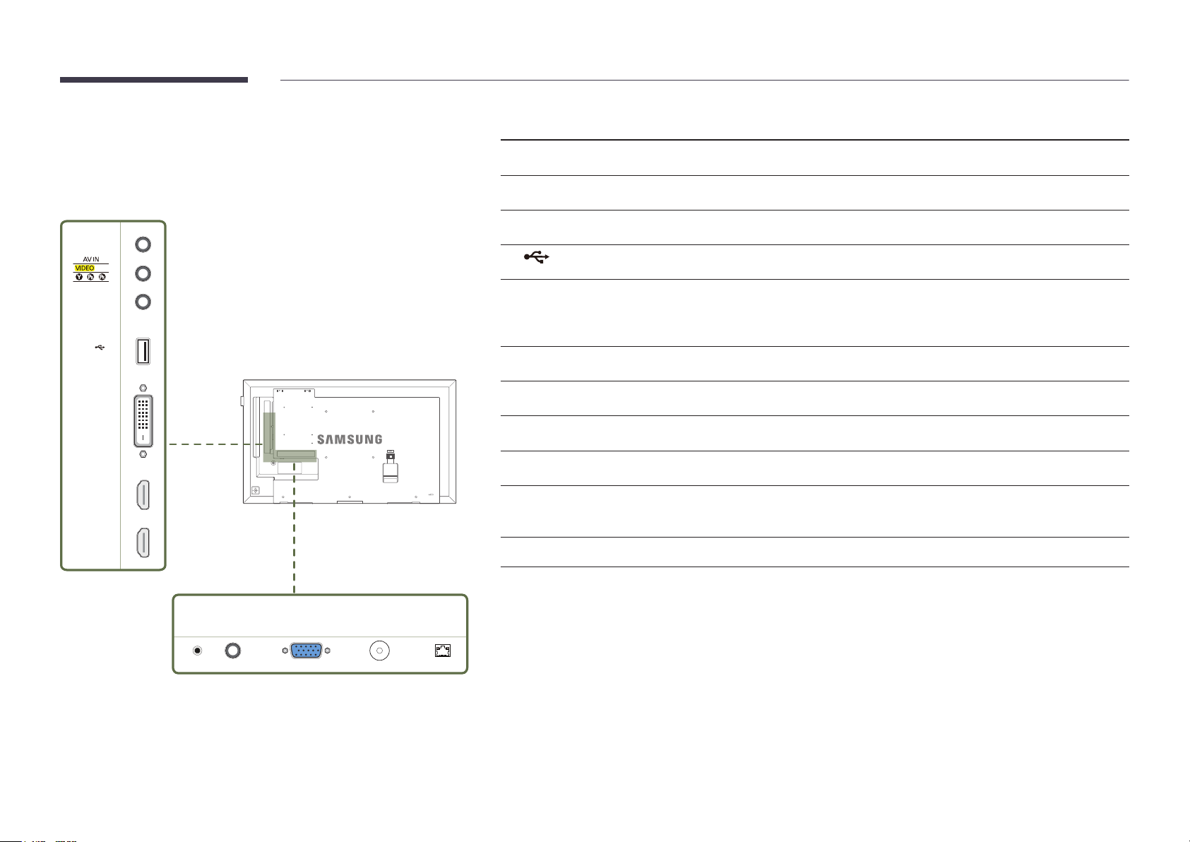
Reverse Side
Port Description
―
The color and shape of parts may differ from what is shown. Specifications are
subject to change without notice to improve quality.
―
EDE, EME models are only supported.
HDBT IN
USB
(5V, 1.5A)
DVI IN /
MAGICINFO IN
HDMI IN
HDBT IN
USB (5V, 1.5A)
DVI IN / MAGICINFO IN
HDMI IN
RGB IN
RS232C IN
RS232C OUT
RGB / DVI / HDMI / AV / COMPONENT /
AUDIO IN
AUDIO OUT
AV IN / COMPONENT IN
Sends the HDMI signal to a connected LAN cable using an HDBaseT transmitter.
―
EME models are only supported.
Connect to a USB memory device.
DVI IN: Connects to a source device using a DVI cable or HDMI-DVI cable.
MAGICINFO IN: Use the (dedicated) DP-DVI cable when connecting a network box
(sold separately).
Connects to a source device using an HDMI cable.
Connects to a source device using a D-SUB cable.
Connects to MDC using an RS232C adapter.
Receives sound from a PC via an audio cable.
Connects to the audio of a source device.
Connects to a source device using the AV/Component adapter.
RGB IN RS232C IN RS232C OUT
RGB / DVI /
HDMI / AV /
COMPONENT
/ AUDIO IN
AUDIO
OUT
COMPONENT IN
IR /
AMBIENT
SENSOR IN
IR / AMBIENT SENSOR IN
Supplies power to the external sensor board or receives the light sensor signal.
18
Page 19
Reverse Side
Port Description
―
The color and shape of parts may differ from what is shown. Specifications are
subject to change without notice to improve quality.
―
DCE, DCE-M, DCE-H models are only supported.
AUDIO OUT
COMPONENT IN
AUDIO IN
USB
(5V, 1.5A)
DVI IN /
MAGICINFO IN
HDMI IN 1
HDMI IN 2
AUDIO OUT
AV IN / COMPONENT IN
AUDIO IN
USB (5V, 1.5A)
DVI IN / MAGICINFO IN
HDMI IN 1, HDMI IN 2
IR IN
RS232C IN
RGB IN
ANT IN
RJ45
Connects to the audio of a source device.
Connects to a source device using the AV/Component adapter.
Receives sound from a PC via an audio cable.
Connect to a USB memory device.
DVI IN: Connects to a source device using a DVI cable or HDMI-DVI cable.
MAGICINFO IN: Use the (dedicated) DP-DVI cable when connecting a network box
(sold separately).
Connects to a source device using an HDMI cable.
Supplies power to the external sensor board or receives the light sensor signal.
Connects to MDC using an RS232C adapter.
Connects to a source device using a D-SUB cable.
Connect to an antenna cable.
―
The DCE-H models are not supported.
Connects to MDC using a LAN cable.
IR IN
RS232C IN RGB IN RJ45ANT IN
19
Page 20

Anti-theft Lock
―
An anti-theft lock allows you to use the product securely even in public places.
―
The locking device shape and locking method depend on the manufacturer. Refer to the user guide provided with your anti-theft locking device for details.
―
The following images are for reference only. Real-life situations may differ from what is shown in the images.
To lock an anti-theft locking device:
―
Stand: Sold separately
Fix the cable of your anti-theft locking device to a heavy object such as a desk.
1
Put one end of the cable through the loop on the other end.
2
Insert the locking device into the anti-theft lock slot at the back of the product.
3
Lock the locking device.
4
-
An anti-theft locking device can be purchased separately.
-
Refer to the user guide provided with your anti-theft locking device for details.
-
Anti-theft locking devices can be purchased at electronics retailers or online.
20
Page 21
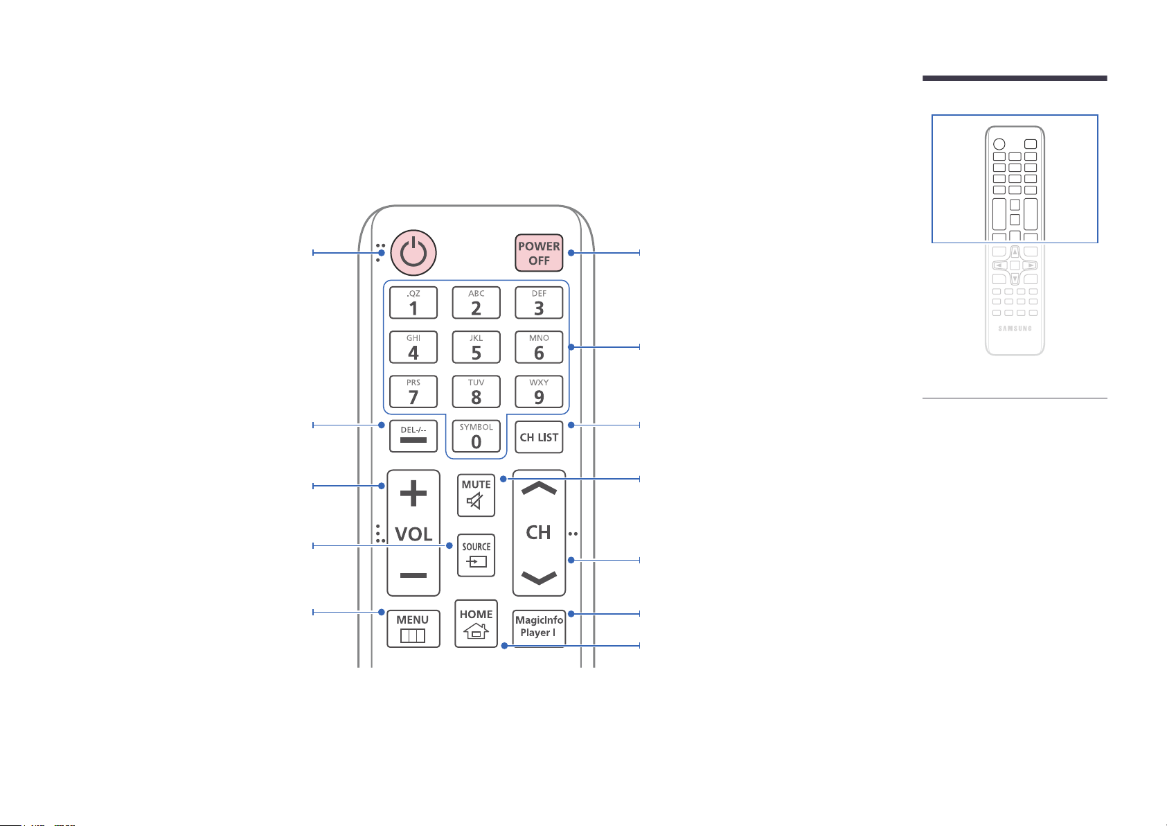
Remote Control
―
Using other display devices in the same space as the remote control of this product can cause the other display devices to be inadvertently controlled.
―
A button without a description in the image below is not supported on the product.
Power on the product.
Press to select additional
channels (digital) being broadcasted by the
same station. For example, to select channel
“54-3”, press “54”, then press “-” and “3”.
Adjust the volume.
Change the input source.
Display or hide the onscreen display menu, or
return to the previous menu.
Power off the product.
Number buttons
Enter the password in the OSD menu.
Channel List Launch Button.
Mute the sound.
Unmuting the sound: Press MUTE again or press
the volume control(+ VOL -) button.
Change the channel in TV mode.
Use this hotkey to directly access MagicInfo.
This hotkey is available when a network box is
connected.
MagicInfo Launch Button.
―
DCE, DCE-M, DCE-H models are only
supported.
-
Remote control button functions may
differ for different products.
21
Page 22
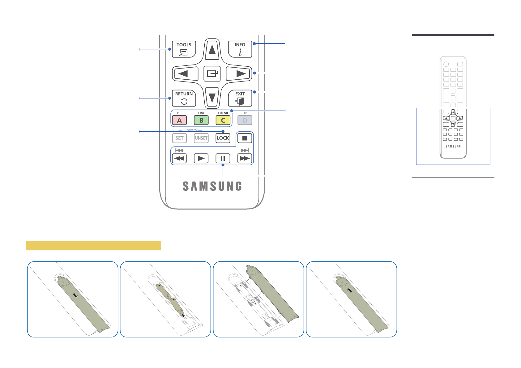
Quickly select frequently used functions.
Return to the previous menu.
It sets safe lock function.
Display information about the current input
source.
Move to the upper, lower, left or right menu, or
adjust an option's setting.
Confirm a menu selection.
Exit the current menu.
Manually select a connected input source from PC,
DVI, HDMI.
In TV mode, configure settings such as the
program guide for digital channels. In other modes,
manually select a connected source device. In
media and HDMI-CEC modes, configure settings
for the functions assigned to the color buttons on
the remote control. Enable or disable lock mode.
Used in Anynet+ mode and multimedia mode.
-
Remote control button functions may
differ for different products.
To place batteries in the remote control
22
Page 23
Before Installing the Product (Installation Guide)
To prevent injury, this apparatus must be securely attached to the floor/wall in accordance with the installation instructions.
•
Ensure that an authorized installation company installs the wall mount.
•
Otherwise, it may fall and cause personal injury.
•
Make sure to install the specified wall mount.
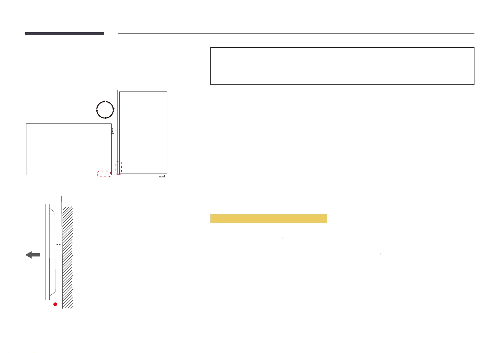
Switching between portrait and landscape
―
Contact Samsung Customer Service Center for further details.
•
To use the product vertically (portrait), turn it clockwise so that the LED is pointing down.
Ventilation
Installation on a Perpendicular Wall
A
B
Figure 1.1 Side view
A Minimum 40 mm
B Ambient temperature: Under 35
•
When installing the product on a perpendicular wall, allow at least 40 mm of space between the product and wall surface
for ventilation and ensure that the ambient A temperature is kept below 35
C
C.
23
Page 24
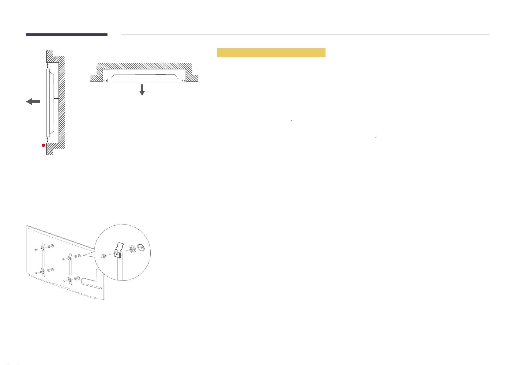
Figure 1.3 Side view
B
Installation on an Indented Wall
―
Contact Samsung Customer Service Center for further details.
D D
A
C
E
Figure 1.2 Side view
Installing the Wall Mount
Plane view
A Minimum 40 mm
B Minimum 70 mm
C Minimum 50 mm
D Minimum 50 mm
E Ambient temperature: Under 35
―
When installing the product on an indented wall, allow at least the space specified above between the product and wall for
ventilation and ensure that the ambient temperature is kept below 35
C
C.
Preparing before installing Wall-Mount
To install a wall-mount from another manufacturer, use the Holder-Ring(1).
―
EDE, EME models are only supported.
Installing the Wall Mount Kit
1
The wall mount kit (sold separately) allows you to mount the product on the wall.
For detailed information on installing the wall mount, see the instructions provided with the wall mount.
We recommend you contact a technician for assistance when installing the wall mount bracket.
Samsung Electronics is not responsible for any damage to the product or injury to yourself or others if you elect to install the
wall mount on your own.
24
Page 25
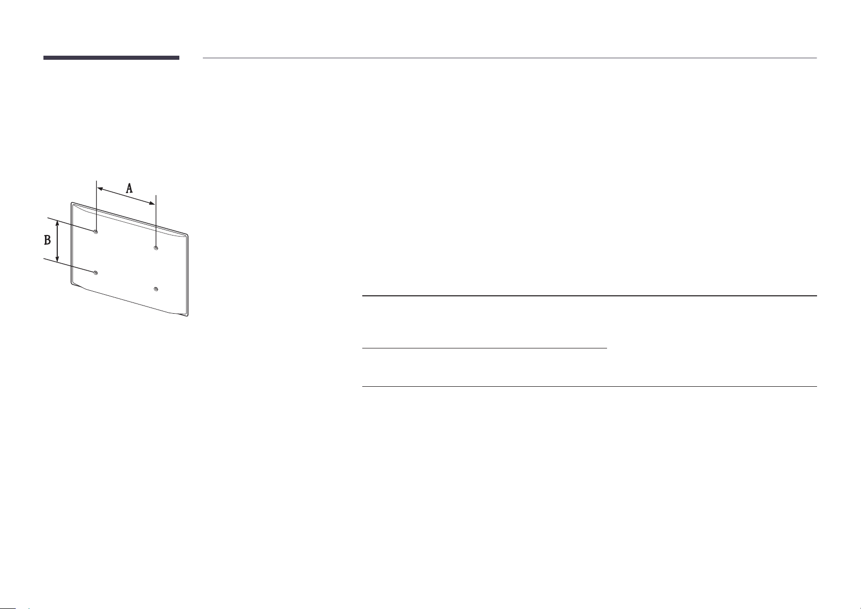
Wall Mount Kit Specications (VESA)
―
Install your wall mount on a solid wall perpendicular to the floor. Before
attaching the wall mount to surfaces other than plaster board, please contact
your nearest dealer for additional information.
If you install the product on a slanted wall, it may fall and result in severe
personal injury.
•
Samsung wall mount kits contain a detailed installation manual and all parts necessary for assembly are provided.
•
Do not use screws that are longer than the standard length or do not comply with the VESA standard screw
specifications. Screws that are too long may cause damage to the inside of the product.
•
For wall mounts that do not comply with the VESA standard screw specifications, the length of the screws may differ
depending on the wall mount specifications.
•
Do not fasten the screws too firmly. This may damage the product or cause the product to fall, leading to personal injury.
Samsung is not liable for these kinds of accidents.
•
Samsung is not liable for product damage or personal injury when a non-VESA or non-specified wall mount is used or the
consumer fails to follow the product installation instructions.
•
Always have two people mount the product on a wall.
•
Standard dimensions for wall mount kits are shown in the table below.
Unit: mm (inches)
Model name VESA screw hole specs
Standard Screw Quantity
(A * B) in millimeters
ED65E / ED75E / EM65E / EM75E
/ DC48E / DC55E / DC48E-M /
DC48E-H / DC55E-M
DC32E / DC40E / DC32E-M /
DC40E-M / DC40E-H
―
Do not install your Wall Mount Kit while your product is turned on. It may result in personal injury due to electric shock.
400 x 400 (15.7 x 15.7) M8, L32 4
200 x 200 (7.9 x 7.9)
25
Page 26
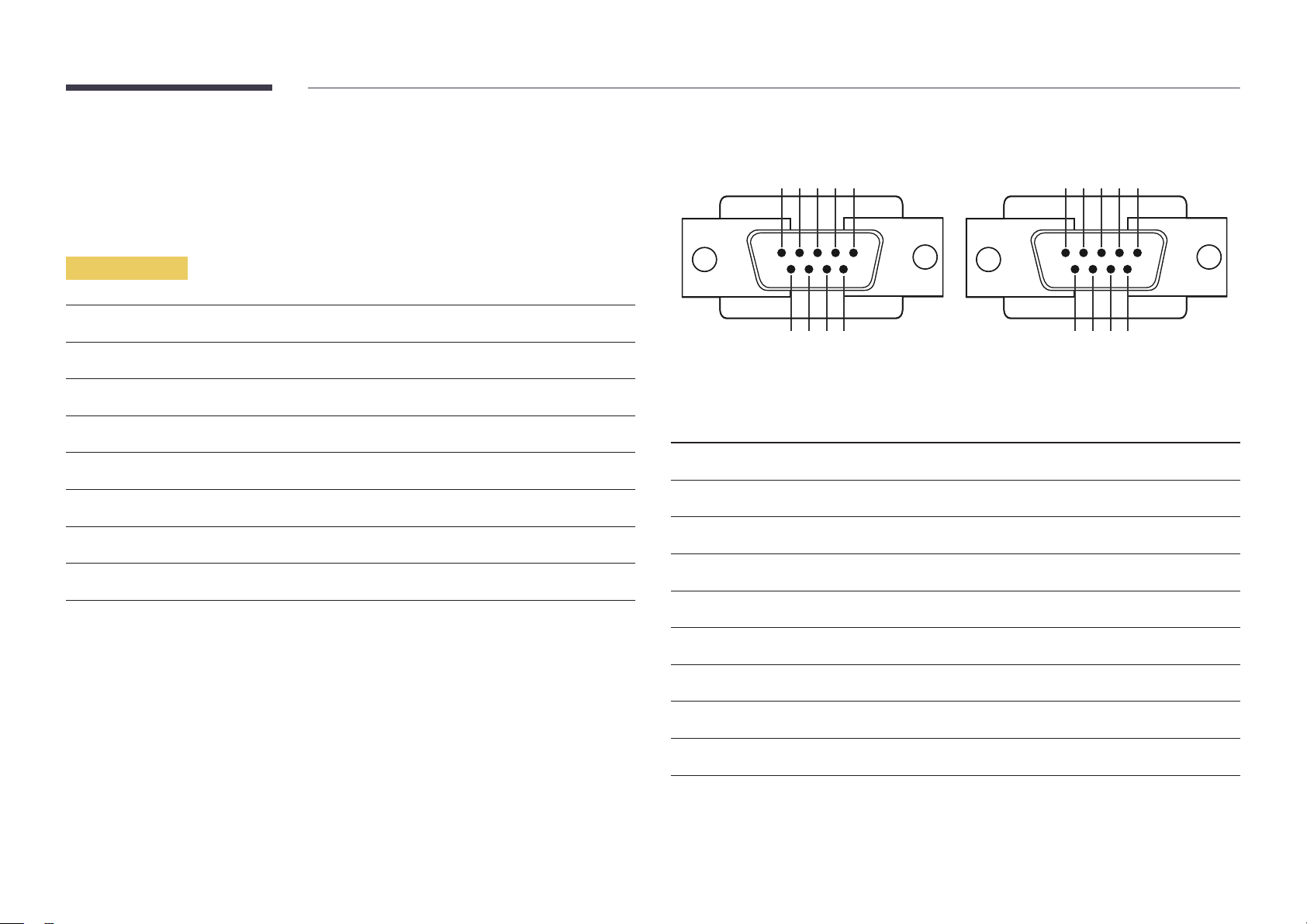
Remote Control (RS232C)
•
Pin assignment
Cable Connection
RS232C Cable
Interface
Pin
Bit rate
Data bits
Parity
Stop bit
Flow control
Maximum length
RS232C (9 pins)
TxD (No.2), RxD (No.3), GND (No.5)
9600 bps
8 bit
None
1 bit
None
15 m (only shielded type)
1 2 3 4 5
6 7 8 9
<Male type> <Female type>
Pin Signal
1
2
3
4
5
Detect data carrier
Received data
Transmitted data
Prepare data terminal
Signal ground
5 4 3 2 1
9 8 7 6
6
7
8
9
Prepare data set
Send request
Clear to send
Ring indicator
26
Page 27
•
RS232C cable
Connector: 9-Pin D-Sub to Stereo Cable
16
5
9
-P1-
-P1- -P1- -P2- -P2-
3
2
1
-P2-
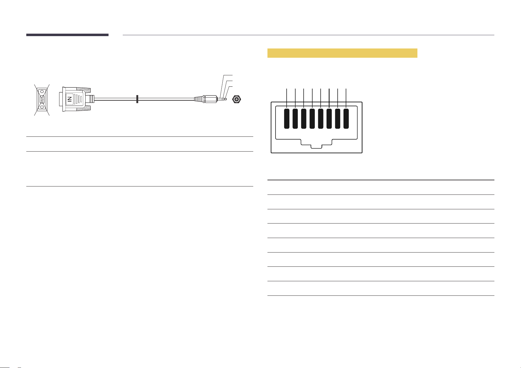
LAN Cable (DCE, DCE-M, DCE-H Model Only)
•
Pin assignment
1 2 3 4 5 6 7 8
Male type Rx
Tx
Gnd
3
2
5
----------
----------
----------
2
1
3
Tx
Rx
Gnd
STEREO
PLUG
(3.5ø)
Pin No Standard Color Signal
1 White and orange TX+
2 Orange TX-
3 White and green RX+
4 Blue NC
5 White and blue NC
6 Green RX-
7 White and brown NC
8 Brown NC
27
Page 28
•
Connector : RJ45
Direct LAN cable (PC to HUB)
Cross LAN cable (PC to PC)
HUB
P1P2
RJ45 RJ45 MDC
Signal
TX+
TX-
RX+
RX-
P1
P1 P2 Signal
1 <--------> 1 TX+
2 <--------> 2 TX-
3 <--------> 3 RX+
6 <--------> 6 RX-
P2
Signal
TX+
TX-
RX+
RX-
RJ45
P1 P2
P1 P2 Signal
1 <--------> 3 RX+
2 <--------> 6 RX-
3 <--------> 1 TX+
6 <--------> 2 TX-
28
Page 29
Connection
―
Ensure you connect each of the adapters to the correct RS232C IN or OUT port on the product.
•
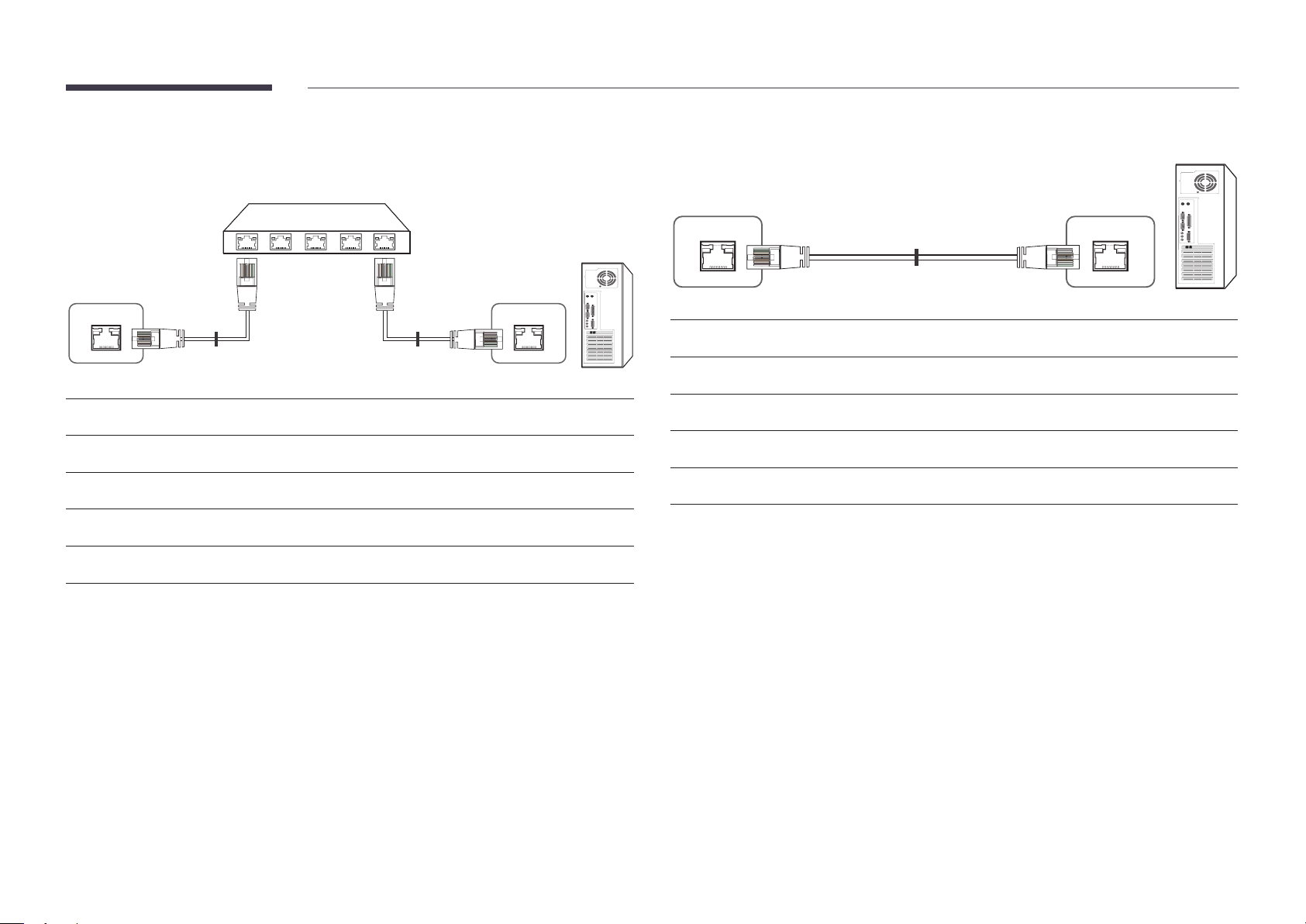
Connection 1 (EDE / EME Model)
•
Connection 2 (DCE / DCE-M / DCE-H Model)
RJ45 RJ45
RS232C
IN OUT
RS232C
IN OUT
RS232C
IN OUT
RS232C
IN OUT
•
Connection 3 (DCE / DCE-M / DCE-H Model)
RS232C
IN
29
Page 30

Control Codes
No. Command type Command Value range
Viewing control state (Get control command)
Header Command ID Data length Checksum
0xAA Command type 0
Controlling (Set control command)
Header Command ID Data length Data Checksum
0xAA Command type 1 Value
Command
No. Command type Command Value range
1
2
3
4
Power control 0x11 0~1
Volume control 0x12 0~100
Input source control 0x14 -
Screen mode control 0x18 -
10
11
•
All communications take place in hexadecimals. The checksum is calculated by adding up all
values except the header. If a checksum adds up to be more than 2 digits as shown below
(11+FF+01+01=112), the first digit is removed.
E.g. Power On & ID=0
Header Command ID Data length Data 1 Checksum
0xAA 0x11 1 "Power"
Header Command ID Data length Data 1 12
0xAA 0x11 1 1
•
To control all devices connected by a serial cable simultaneously irrespective of IDs, set the ID as
"0xFE" and transmit commands. Commands will be executed by each device but ACK will not
respond.
Video Wall On 0x84 0~1
Video Wall User Control 0x89 -
5
6
7
8
9
Screen size control 0x19 0~255
PIP on/off control 0x3C 0~1
Auto adjustment control (PC and
BNC only)
Video wall mode control 0x5C 0~1
Safety Lock 0x5D 0~1
0x3D 0
30
Page 31

Power control
Volume control
•
Function
A product can be powered on and off using a PC.
•
Viewing power state (Get Power ON / OFF Status)
Header Command ID Data length Checksum
0xAA 0x11 0
•
Setting power ON/Off (Set Power ON / OFF)
Header Command ID Data length Data Checksum
0xAA 0x11 1 "Power"
"Power": Power code to be set on a product.
1: Power ON
0: Power OFF
•
Ack
Header Command ID Data length Ack/Nak r-CMD Val1 Checksum
0xAA 0xFF 3 'A' 0x11 "Power"
"Power": Power code to be set on a product.
•
Nak
Header Command ID Data length Ack/Nak r-CMD Val1 Checksum
•
Function
The volume of a product can be adjusted using a PC.
•
Viewing volume state (Get Volume Status)
Header Command ID Data length Checksum
0xAA 0x12 0
•
Setting the volume (Set Volume)
Header Command ID Data length Data Checksum
0xAA 0x12 1 "Volume"
"Volume": Volume value code to be set on a product. (0-100)
•
Ack
Header Command ID Data length Ack/Nak r-CMD Val1 Checksum
0xAA 0xFF 3 'A' 0x12 "Volume"
"Volume": Volume value code to be set on a product. (0-100)
•
Nak
Header Command ID Data length Ack/Nak r-CMD Val1 Checksum
0xAA 0xFF 3 'N' 0x12 "ERR"
0xAA 0xFF 3 'N' 0x11 "ERR"
"ERR" : A code showing what error has occurred.
"ERR" : A code showing what error has occurred.
31
Page 32

Input source control
•
Function
The input source of a product can be changed using a PC.
•
Viewing input source state (Get Input Source Status)
Header Command ID Data length Checksum
0xAA 0x14 0
•
Setting the input source (Set Input Source)
Header Command ID Data length Data Checksum
0xAA 0x14 1 "Input Source"
"Input Source": An input source code to be set on a product.
0x24 HDMI2_PC
0x55 HDBT
―
DVI_video, HDMI1_PC(HDMI_PC) and HDMI2_PC cannot be used with the Set command. They only
respond to "Get" commands.
―
Available input sources may vary depending on the model.
―
MagicInfo is only available with models that contain the MagicInfo function.
―
RF(TV), DTV are only available with models that include a TV.
•
Ack
Header Command ID Data length Ack/Nak r-CMD Val1 Checksum
0xAA 0xFF 3 'A' 0x14 "Input
Source"
0x14 PC
0x18 DVI
0x0C Input source
0x08 Component
0x20 MagicInfo
0x1F DVI_video
0x30 RF(TV)
0x40 DTV
0x21 HDMI1(HDMI)
0x22 HDMI1_PC(HDMI_PC)
0x23 HDMI2
"Input Source": An input source code to be set on a product.
•
Nak
Header Command ID Data length Ack/Nak r-CMD Val1 Checksum
0xAA 0xFF 3 'N' 0x14 "ERR"
"ERR" : A code showing what error has occurred.
32
Page 33

Screen mode control
•
Function
The screen mode of a product can be changed using a PC.
Screen mode cannot be controlled when the Video Wall function is enabled.
―
This control can only be used on models that include a TV.
•
Viewing screen status (Get Screen Mode Status)
Header Command ID Data length Checksum
0xAA 0x18 0
•
Setting the picture size (Set Picture Size)
Header Command ID Data
length
0xAA 0x18 1 "Screen Mode"
"Screen Mode": A code that sets the product status
0x01 16 : 9
Data Checksum
•
Nak
Header Command ID Data length Ack/Nak r-CMD Val1 Checksum
0xAA 0xFF 3 'N' 0x18 "ERR"
"ERR": A code showing what error has occurred
Screen size control
•
Function
The screen size of a product can be changed using a PC.
•
Viewing the screen size (Get Screen Size Status)
Header Command ID Data length Checksum
0xAA 0x19 0
•
Ack
Header Command ID Data
length
Ack/Nak r-CMD Val1 Checksum
0x04 Zoom
0x31 Wide Zoom
0x0B 4 : 3
•
Ack
Header Command ID Data length Ack/Nak r-CMD Val1 Checksum
0xAA 0xFF 3 'A' 0x18 "Screen
Mode"
"Screen Mode": A code that sets the product status
0xAA 0xFF 3 'A' 0x19 "Screen Size"
"Screen Size": product screen size (range: 0 – 255, unit: inch)
•
Nak
Header Command ID Data
length
0xAA 0xFF 3 'N' 0x19 "ERR"
"ERR": A code showing what error has occurred
Ack/Nak r-CMD Val1 Checksum
33
Page 34

PIP On/Off control
Auto adjustment control (PC and BNC only)
•
Function
The PIP mode of a product can be turned on or off using a PC.
―
Only available on models that have the PIP function.
―
The mode cannot be controlled if Video Wall is set to On.
―
This function is not available in MagicInfo.
•
Viewing PIP on/off state (Get the PIP ON / OFF Status)
Header Command ID Data length Checksum
0xAA 0x3C 0
•
Setting PIP on/off (Set the PIP ON / OFF)
Header Command ID Data length Data Checksum
0xAA 0x3C 1 "PIP"
"PIP": A code used to turn the PIP mode of a product on or off
1: PIP ON
0: PIP OFF
•
Ack
Header Command ID Data
length
0xAA 0xFF 3 'A' 0x3C "PIP"
Ack/Nak r-CMD Val1 Checksum
•
Function
Automatically adjust the PC system screen using a PC.
•
Viewing auto adjustment state (Get Auto Adjustment Status)
None
•
Setting auto adjustment (Set Auto Adjustment)
Header Command ID Data length Data Checksum
0xAA 0x3D 1 "Auto
Adjustment"
"Auto Adjustment" : 0x00 (at all times)
•
Ack
Header Command ID Data
length
0xAA 0xFF 3 'A' 0x3D "Auto
•
Nak
Header Command ID Data
length
0xAA 0xFF 3 'A' 0x3D "ERR"
Ack/Nak r-CMD Val1 Checksum
Adjustment"
Ack/Nak r-CMD Val1 Checksum
"PIP": A code used to turn the PIP mode of a product on or off
•
Nak
Header Command ID Data
length
0xAA 0xFF 3 'A' 0x3C "PIP"
"ERR": A code showing what error has occurred
Ack/Nak r-CMD Val1 Checksum
"ERR": A code showing what error has occurred
34
Page 35

Video Wall Mode Control
Safety Lock
•
Function
Video Wall mode can be activated on a product using a PC.
This control is only available on a product whose Video Wall is enabled.
•
Viewing video wall mode (Get Video Wall Mode)
Header Command ID Data length Checksum
0xAA 0x5C 0
•
Setting the video wall (Set Video Wall Mode)
Header Command ID Data length Data Checksum
0xAA 0x5C 1 "Video Wall Mode"
"Video Wall Mode": A code used to activate Video Wall mode on a product
1: Full
0: Natural
•
Ack
Header Command ID Data
length
0xAA 0xFF 3 'A' 0x5C "Video Wall
"Video Wall Mode": A code used to activate Video Wall mode on a product
•
Nak
Header Command ID Data
length
0xAA 0xFF 3 'A' 0x5C "ERR"
"ERR": A code showing what error has occurred
Ack/Nak r-CMD Val1 Checksum
Mode"
Ack/Nak r-CMD Val1 Checksum
•
Function
PC can be used to turn the Safety Lock function on or off on a product.
This control is available regardless of whether or not the power is turned on.
•
Viewing the safety lock state (Get Safety Lock Status)
Header Command ID Data length Checksum
0xAA 0x5D 0
•
Enabling or disabling safety lock (Set Safety Lock Enable / Disable)
Header Command ID Data length Data Checksum
0xAA 0x5D 1 "Safety Lock"
"Safety Lock": Safety lock code to be set on a product
1: ON
0: OFF
•
Ack
Header Command ID Data
length
0xAA 0xFF 3 'A' 0x5D "Safety Lock"
"Safety Lock": Safety lock code to be set on a product
•
Nak
Header Command ID Data
length
0xAA 0xFF 3 'N' 0x5D "ERR"
"ERR": A code showing what error has occurred
Ack/Nak r-CMD Val1 Checksum
Ack/Nak r-CMD Val1 Checksum
35
Page 36

Video Wall On
•
Function
Turn Video Wall on or off on the product from your computer.
•
Get Video Wall On/Off Status
Header Command ID Data length Checksum
•
Nak
Header Command ID Data length Ack/Nak r-CMD Val1 Checksum
0xAA 0xFF 3 'N' 0x84 ERR
"ERR": A code showing what error has occurred
0xAA 0x84 0
•
Set Video Wall On/Off
Header Command ID Data length Data Checksum
0xAA 0x84 1 V.Wall_On
•
V.Wall_On: Video Wall code to be assigned to the product
1: Video Wall ON
0: Video Wall OFF
•
Ack
Header Command ID Data length Ack/Nak r-CMD Val1 Checksum
0xAA 0xFF 3 'A' 0x84 V.Wall_
On
V.Wall_On : Same as above
Video Wall User Control
•
Function
Turn the Video Wall function on or off on the product from your computer.
•
Get Video Wall Status
Header Command ID Data length Checksum
0xAA 0x89 0
•
Set Video Wall
Header Command ID Data length Val1 Val2 Checksum
0xAA 0x89 2 Wall_Div Wall_SNo
Wall_Div: Video Wall Divider code assigned to the product
36
Page 37

10x10 Video Wall Model
O
1
2
3
4
5
6
7
8
9
10
11
1 2 3 4 5 6 7 8 9 10 11 12 13 14
0x00 0x00 0x00 0x00 0x00 0x00 0x00 0x00 0x00 0x00 0x00 0x00 0x00 0x00
0x11 0x12 0x13 0x14 0x15 0x16 0x17 0x18 0x19 0x1A 0x1B 0x1C 0x1D 0x1E
0x21 0x22 0x23 0x24 0x25 0x26 0x27 0x28 0x29 0x2A 0x2B 0x2C 0x2D 0x2E
0x31 0x32 0x33 0x34 0x35 0x36 0x37 0x38 0x39 0x3A 0x3B 0x3C 0x3D 0x3E
0x41 0x42 0x43 0x44 0x45 0x46 0x47 0x48 0x49 0x4A 0x4B 0x4C 0x4D 0x4E
0x51 0x52 0x53 0x54 0x55 0x56 0x57 0x58 0x59 0x5A 0x5B 0x5C 0x5D 0x5E
0x61 0x62 0x63 0x64 0x65 0x66 0x67 0x68 0x69 0x6A 0x6B 0x6C 0x6D 0x6E
0x71 0x72 0x73 0x74 0x75 0x76 0x77 0x78 0x79 0x7A 0x7B 0x7C 0x7D 0x7E
0x81 0x82 0x83 0x84 0x85 0x86 0x87 0x88 0x89 0x8A 0x8B 0x8C N/A N/A
0x91 0x92 0x93 0x94 0x95 0x96 0x97 0x98 0x99 0x9A 0x9B N/A N/A N/A
0xA1 0xA2 0xA3 0xA4 0xA5 0xA6 0xA7 0xA8 0xA9 0xAA N/A N/A N/A N/A
0xB1 0xB2 0xB3 0xB4 0xB5 0xB6 0xB7 0xB8 0xB9 N/A N/A N/A N/A N/A
15
0x00
0x1F
0x2F
0x3F
0x4F
0x5F
0x6F
N/A
N/A
N/A
N/A
N/A
12
13
14
15
0xC1 0xC2 0xC3 0xC4 0xC5 0xC6 0xC7 0xC8 N/A N/A N/A N/A N/A N/A
0xD1 0xD2 0xD3 0xD4 0xD5 0xD6 0xD7 N/A N/A N/A N/A N/A N/A N/A
0xE1 0xE2 0xE3 0xE4 0xE5 0xE6 0xE7 N/A N/A N/A N/A N/A N/A N/A
0xF1 0xF2 0xF3 0xF4 0xF5 0xF6 N/A N/A N/A N/A N/A N/A N/A N/A
N/A
N/A
N/A
N/A
37
Page 38

Wall_SNo: Product Number code assigned to the product
10x10 Video Wall Model : ( 1 ~ 100)
Set Number
1 0x01
2 0x02
... ...
99 0x63
100 0x64
•
Ack
Header Command ID Data length Ack/Nak r-CMD Val1 Val2 Checksum
0xAA 0xFF 4 'A' 0x89 Wall_Div Wall_SNo
•
Nak
Header Command ID Data length Ack/Nak r-CMD Val1 Checksum
0xAA 0xFF 3 'N' 0x89 ERR
"ERR": A code showing what error has occurred
Data
38
Page 39

Chapter 03
Connecting and Using a Source Device
Before Connecting
Check the following before you connect this product with other devices. Devices that can be connected
to this product include PCs, camcorders, speakers, set top boxes and DVD/Blu-ray Disc players.
Pre-connection Checkpoints
―
Before connecting a source device, read the user manual provided with it.
The number and locations of ports on source devices may differ from device to device.
―
Do not connect the power cable until all connections are completed.
Connecting the power cable during connection may damage the product.
―
Connect the sound ports correctly: left = white and right = red.
―
Check the types of ports at the back of the product you want to connect.
Connecting to a PC
•
Do not connect the power cable before connecting all other cables.
Ensure you connect a source device first before connecting the power cable.
•
A PC can be connected to the product in a variety of ways.
Select a connection method suitable for your PC.
―
Connecting parts may differ in different products.
Connection using the D-SUB cable (Analog type)
RGB IN
RGB / DVI / HDMI / AV / COMPONENT /
AUDIO IN or AUDIO IN
39
Page 40

Connection using a DVI cable (Digital type)
DVI IN /
MAGICINFO IN
RGB / DVI / HDMI / AV / COMPONENT /
AUDIO IN or AUDIO IN
―
You can use the DVI port on the product as an HDMI port by using a DVI-HDMI adapter.
Connection Using an HDMI-DVI Cable
―
When you connect a PC to the product using an HDMI-DVI cable, set Edit Name to DVI PC to access
video and audio content stored on the PC.
HDMI IN
RGB / DVI / HDMI / AV / COMPONENT /
AUDIO IN or AUDIO IN
DVI IN /
MAGICINFO IN
HDMI
40
Page 41

Connection Using an HDMI Cable
HDMI IN
41
Page 42

Connecting to a Video Device
•
Do not connect the power cable before connecting all other cables.
Ensure you connect a source device first before connecting the power cable.
•
You can connect a video device to the product using a cable.
―
Connecting parts may differ in different products.
―
Press the SOURCE button on the remote control to change the source.
Connection Using the AV Cable
AV IN / COMPONENT IN
RGB / DVI / HDMI / AV / COMPONENT /
AUDIO IN or AUDIO IN
Connection Using the component Cable
AV IN / COMPONENT IN
RGB / DVI / HDMI / AV / COMPONENT /
AUDIO IN or AUDIO IN
42
Page 43

Connection Using an HDMI-DVI Cable
―
Audio will not be enabled if the product is connected to a video device using an HDMI-DVI cable. To resolve this, additionally connect an audio cable to the audio ports on the product and video device. When you
connect a video device to the product using an HDMI-DVI cable, set Edit Name to DVI Devices to access video and audio content stored on the video device.
―
Supported resolutions include 1080p (50/60Hz), 720p (50/60Hz), 480p, and 576p.
HDMI IN
RGB / DVI / HDMI / AV / COMPONENT /
AUDIO IN or AUDIO IN
DVI IN /
MAGICINFO IN
HDMI
43
Page 44

Connection Using an HDMI Cable
Connecting to an Audio System
Using an HDMI cable or HDMI to DVI Cable (up to 1080p)
•
For better picture and audio quality, connect to a digital device using an HDMI cable.
•
An HDMI cable supports digital video and audio signals, and does not require an audio cable.
-
To connect the product to a digital device that does not support HDMI output, use an HDMIDVI and audio cables.
•
The picture may not display normally (if at all) or the audio may not work if an external device that
uses an older version of HDMI mode is connected to the product. If such a problem occurs, ask
the manufacturer of the external device about the HDMI version and, if out of date, request an
upgrade.
•
Be sure to use an HDMI cable with a thickness of 14 mm or less.
•
Be sure to purchase a certified HDMI cable. Otherwise, the picture may not display or a connection
error may occur.
•
A basic high-speed HDMI cable or one with ethernet is recommended.
This product does not support the ethernet function via HDMI.
―
Connecting parts may differ in different products.
AUDIO OUT
HDMI IN
44
Page 45

Connecting the Antenna
Connecting the LAN Cable
―
DCE, DCE-M models are only supported.
―
Connecting parts may differ in different products.
―
When the product is powered on for the first time, basic settings are configured automatically. Take
extra care to ensure the wires inside the antenna cable are not bent.
ANT IN
―
DCE, DCE-M, DCE-H models are only supported.
―
Connecting parts may differ in different products.
RJ45
•
Use Cat7(*STP Type) cable for the connection.
*Shielded Twist Pair
45
Page 46

Connecting the HDBase-T
―
EME models are only supported.
―
Connecting parts may differ in different products.
―
HDBase-T (Tx) transmits data from an external device to HDBase-T (Rx). Make sure to connect them directly using a LAN cable.
―
Data transmission is not available if HDBase-T (Rx) is connected to HDBase-T (Tx) through a hub.
―
HDBase-T works with unshielded twisted pair (UTP) or shielded twisted pair (STP) cables; but, to ensure CE compliance, STP cables and STP Connectors are required.
Shielded cable and connectors are recommended to safeguard against unpredictable environmental electrical noise which may impact performance.
It is recommended to use an STP cable to maximize performance. Using a UTP cable or patch may decrease performance.
HDMI OUT
HDBT IN
LAN Cable
HDBase-T (Tx)HDBase-T (Rx)
LAN HDMI IN
HDMI OUT
HDMI OUT
46
Page 47

Changing the Input source
Source
MENU m → Applications → Source List → ENTER E
Source
Source allows you to select a variety of sources and change source device names.
You can display the screen of a source device connected to the product. Select a source from source list to display the screen
of the selected source.
―
The input source can also be changed by using the SOURCE button on the remote control.
―
The screen may not display correctly if an incorrect source is selected for the source device you want to convert to.
HDMI
-
The displayed image may differ depending on the model.
HDMI-CEC
DVD Player
AV PCComponent
DVI
47
Page 48

Chapter 04
Using MDC
Multiple display control "MDC" is an application that allows you to easily control multiple display devices simultaneously using a PC.
- For details on how to use the MDC program, refer to Help after installing the program. The MDC program is available on the website.
MDC Program Installation/Uninstallation
Installation
―
MDC installation can be affected by the graphics card, mother board and network conditions.
Click the MDC Unified installation program.
1
Select a language for installation. Next, click "OK".
2
When the "Welcome to the InstallShield Wizard for MDC_Unified" screen appears, click "Next".
3
In the "License Agreement" window displayed, select "I accept the terms in the license
4
agreement" and click "Next".
7
8
9
10
Uninstallation
In the displayed "Ready to Install the Program" window, check the directory path to install the
program in and click "Install".
Installation progress will be displayed.
Click "Finish" in the displayed "InstallShield Wizard Complete" window.
―
Select "Launch MDC Unified" and click "Finish" to run the MDC program immediately.
The MDC Unified shortcut icon will be created on the desktop after installation.
―
The MDC execution icon may not be displayed depending on the PC system or product
specifications.
―
Press F5 if the execution icon is not displayed.
In the displayed "Customer Information" window, fill out all the information fields and click
5
"Next".
In the displayed "Destination Folder" window, select the directory path you want to install the
6
program in and click "Next".
―
If the directory path is not specified, the program will be installed in the default directory path.
Select Settings > Control Panel on the Start menu and double-click Add/Delete Program.
1
Select MDC Unified from the list and click Change/Remove.
2
48
Page 49

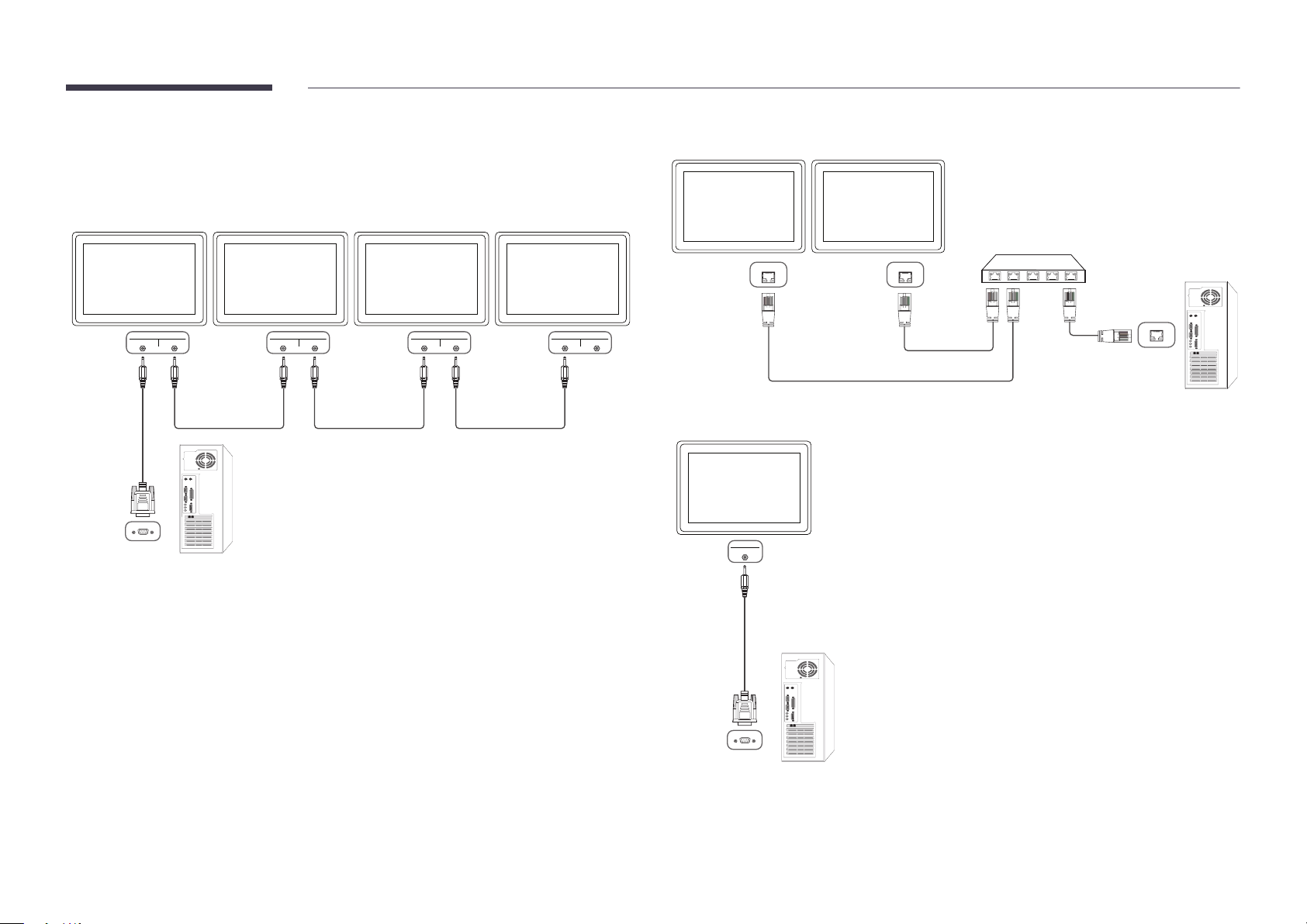
Connecting to MDC
Using MDC via RS-232C (serial data communications standards)
An RS-232C serial cable must be connected to the serial ports on the PC and monitor.
―
EDE, EME models are only supported.
Monitor 1
RS232C IN RS232C OUT
Monitor 2
Computer
49
Page 50

Using MDC via Ethernet
Enter the IP for the primary display device and connect the device to the PC. Display devices can be connected to each other using a LAN cable.
Connection using a direct LAN cable
―
Multiple products can be connected using the RJ45 port on the product and the LAN ports on the HUB.
―
DCE, DCE-M, DCE-H models are only supported.
Computer
RJ45
HUB
Monitor 1
Monitor 2
50
Page 51

Chapter 05
Screen Adjustment
Configure the Picture settings (Backlight, Color Tone, etc.).
The layout of the Picture menu options may vary depending on the product.
Picture Mode
MENU m → Picture → Picture Mode → ENTER E
Picture
Picture Mode Information
·
Backlight
·
Contrast
·
Brightness
·
Sharpness
·
Color
·
Tint (G/R)
-
The displayed image may differ depending on the model.
-
Calibration is only available on the DCE-M, DCE-H models.
G50 R
50 50
100
100
100
100
45
45
50
50
50
50
50
Select a picture mode (Picture Mode) suitable for the environment where the product will be used.
Different Picture Mode options are displayed depending on the current input source.
If the input source is PC, DVI, HDMI(PC)
•
Information: This mode reduces eye fatigue and is suitable for displaying information to the public.
•
Advertisement: This mode is suitable for displaying video content and indoor/outdoor advertisements.
•
Calibration: In this mode, the brightness, color, gamma and uniformity settings customized using the color calibration
program Advanced Color Management are applied.
-
To apply the Calibration mode properly, make sure you configure the picture quality settings, such as brightness,
color, gamma and uniformity, using the color calibration program Advanced Color Management.
-
To download the Advanced Color Management program, visit www.samsung.com/displaysolutions.
If the input source is TV, AV, Component, HDMI(AV )
•
Dynamic: This mode is suitable when the ambient light is bright.
•
Standard: This mode is generally suitable for any environment.
•
Movie: This mode reduces eye fatigue.
•
Calibration: In this mode, the brightness, color, gamma and uniformity settings customized using the color calibration
program Advanced Color Management are applied.
-
To apply the Calibration mode properly, make sure you configure the picture quality settings, such as brightness,
color, gamma and uniformity, using the color calibration program Advanced Color Management.
-
To download the Advanced Color Management program, visit www.samsung.com/displaysolutions.
51
Page 52

Backlight / Contrast / Brightness / Sharpness / Color / Tint (G/R)
MENU m → Picture → ENTER E
Picture
Picture Mode Information
Your product has several options for adjusting picture quality.
Input source Picture Mode Adjustable options
PC, DVI, HDMI, HDBT (when a PC is
connected)
TV, AV, Component, HDMI, HDBT
(720p, 1080i, 1080p)
Information / Advertisement Backlight / Contrast / Brightness /
Sharpness
Calibration Backlight
Dynamic / Standard / Movie Backlight / Contrast / Brightness /
Sharpness / Color / Tint (G/R)
·
Backlight
·
Contrast
·
Brightness
·
Sharpness
·
Color
·
Tint (G/R)
-
The displayed image may differ depending on the model.
G50 R
50 50
Gamma
MENU m → Picture → Gamma → ENTER E
Gamma 0
100
100
100
100
45
45
50
50
50
50
50
Calibration Backlight
―
When you make changes to Backlight, Contrast, Brightness, Sharpness, Color or Tint (G/R), the OSD will be adjusted
accordingly.
―
You can adjust and store settings for each external device you have connected to an input on the product.
―
Lowering picture brightness reduces power consumption.
Adjust the primary color intensity.
―
If Picture Mode is set to Calibration, Gamma is disabled.
-
The displayed image may differ depending on the model.
52
Page 53

Calibrated Value
MENU m → Picture → Calibrated Value → ENTER E
Picture
Calibrated Value Don't Apply
-
The displayed image may differ depending on the model.
Select whether to apply the brightness, color, gamma and uniformity settings customized using the color calibration program
Advanced Color Management to the Information and Advertisement modes.
•
Don't Apply / Apply
―
To download the Advanced Color Management program, visit www.samsung.com/displaysolutions.
―
If Picture Mode is set to Calibration, Calibrated Value is disabled.
―
DCE-M, DCE-H models are only supported.
53
Page 54

Picture Size
MENU m → Picture → Picture Size → ENTER E
Picture Size
Picture Size
·
Position
Resolution Select
-
The displayed image may differ depending on the model.
16:9
O
Picture Size
If you have a cable box or satellite receiver, it may have its own set of screen sizes as well. However, we highly recommend you
use your product’s 16:9 mode most of the time.
―
Different screen adjustment options are displayed depending on the current input source.
•
16:9: Sets the picture to 16:9 wide mode.
•
Zoom1: Use for moderate magnification. Cuts off the top and sides.
•
Zoom2: Use for a stronger magnification.
•
Smart View 1: Reduces the 16:9 picture by 50%.
―
Smart View 1 is enabled only in HDMI mode.
•
Smart View 2: Reduces the 16:9 picture by 25%.
―
Smart View 2 is enabled only in HDMI mode.
•
Wide Fit: Enlarges the aspect ratio of the picture to fit the entire screen.
•
4:3: Sets the picture to basic (4:3) mode.
―
Do not set your product to 4:3 format for a long time.
The borders displayed on the left and right, or top and bottom of the screen may cause image retention (screen burn)
which is not covered by the warranty.
•
Screen Fit: Displays the full image without any cut-off when HDMI (720p / 1080i / 1080p) or Component (1080i / 1080p)
signals are inputted.
•
Custom: Changes the resolution to suit the user's preferences.
•
Original Ratio: If the input source is PC, DVI, HDMI (PC connection) the video will display in the original aspect ratio.
―
Available ports may differ depending on the model.
―
You can adjust and store settings for each external device you have connected to an input on the product.
54
Page 55

Position
Picture Size
Picture Size
·
Position
Zoom1
Adjusts the picture position. Position is only available if Picture Size is set to Zoom1, Zoom2, Wide Fit, Screen Fit.
―
To use the Position function after selecting Zoom1, Zoom2, Wide Fit or Screen Fit follow these steps.
Press the d button to select Position. Press the E button.
1
Press the u or d button to move the picture up or down.
2
Press the E button.
3
Resolution Select
-
The displayed image may differ depending on the model.
Zoom/Position
Picture Size
Picture Size
·
Zoom/Position
Resolution Select
O
Custom
O
―
To use the Zoom/Position function after selecting Custom in HDMI (1080i/1080p) or Component (1080i/1080p) or
Custom, follow these steps.
Press the d button to select Zoom/Position. Press the E button.
1
Select the Zoom or Position. Press the E button.
2
Press the u/d/l/r button to move the picture.
3
Press the E button.
4
―
If you want to reset the picture to its original position, select Reset in the Zoom/Position screen.
The picture will be set to its default position.
-
The displayed image may differ depending on the model.
55
Page 56

Resolution Select
Picture Size
If the picture is not normal even when the resolution of the graphics card is one of the following, you can optimize the picture
quality by selecting the same resolution for the product as the PC using this menu.
Available resolutions: Off / 1024x768 / 1280x768 / 1360x768 / 1366x768
Picture Size
·
Position
Resolution Select
-
Available in PC mode only.
-
The displayed image may differ depending on the model.
16:9
O
Auto Adjustment
MENU m → Picture → Auto Adjustment → ENTER E
Picture
Auto Adjustment
Adjust frequency values/positions and fine tune the settings automatically.
-
Available in PC mode only.
-
The displayed image may differ depending on the model.
56
Page 57

PC Screen Adjustment
MENU m → Picture → PC Screen Adjustment → ENTER E
PC Screen Adjustment
Coarse
Fine
Position
Image Reset
-
Available in PC mode only.
-
The displayed image may differ depending on the model.
50
0
•
Coarse / Fine
Removes or reduces picture noise.
If the noise is not removed by Fine-tuning alone, use the Coarse function to adjust the frequency as best as possible
(Coarse) and Fine-tune again. After the noise has been reduced, re-adjust the picture so that it is aligned with the center
of screen.
•
Position
To adjust the PC’s screen position if it is not centered or does not fit the product screen.
Press the u or d button to adjust the Vertical Position. Press the l or r button to adjust the Horizontal Position.
•
Image Reset
Resets the image to the default settings.
57
Page 58

PIP
MENU m → Picture → PIP → ENTER E
Picture
PIP Settings
The picture from the external video source will be in the main screen and the picture from the product will be in the PIP subpicture screen.
Main picture Sub picture
TV Component, PC, DVI, HDMI, MagicInfo
PIP
-
The displayed image may differ depending on the model.
-
For PIP sound, refer to the Sound Select instructions.
-
If you turn the product off while watching in the PIP mode, the PIP function is reset to off.
When you turn your product on, you must turn PIP on again to watch in the PIP mode.
-
You may notice that the picture in the PIP screen becomes slightly unnatural when you use
the main screen to view a game or karaoke.
AV PC, DVI, HDMI, MagicInfo, HDBT
Component TV, DVI, HDMI, MagicInfo, HDBT
PC TV, AV, DVI, HDMI, MagicInfo, HDBT
DVI, HDMI TV, AV, Component, PC
HDBT PC, AV, Component
―
Available input sources may vary depending on the model.
•
PIP (Off / On): Activate or deactivate the PIP function.
•
Source: You can select a source of the sub picture.
•
Antenna (Air / Cable): Select either Air or Cable as the input source for the sub-screen.
―
This option is enabled if the secondary display is set to TV.
―
DCE, DCE-M models are only supported.
•
Channel: Select the channel for the sub-screen.
―
This option is enabled if the secondary display is set to TV.
―
DCE, DCE-M models are only supported.
•
Size (
•
Position (
―
•
Sound Select (Main / Sub): You can choose to listen to the sound from the Main picture or the Sub picture.
, , , , , ): Select a size for the subpicture.
, , , ): Select a position for the sub-picture.
In (
, , ) mode, you cannot select Position.
58
Page 59

Advanced Settings
MENU m → Picture → Advanced Settings → ENTER E
Input Source Picture Mode Advanced Settings
PC, DVI, HDMI, MagicInfo,
HDBT (when a PC is connected)
Information White Balance
Advertisement White Balance
Advanced Settings
Dynamic Contrast
Black Tone
Flesh Tone
RGB Only Mode
Color Space
White Balance
Motion Lighting
-
The displayed image may differ depending on the model.
Medium
O
O
Native
O
TV, AV, Component, DVI,
HDMI, HDBT
TV, AV, Component, DVI,
HDMI, HDBT
0
―
Available input sources may vary depending on the model.
―
If Picture Mode is set to Calibration, Advanced Settings is disabled.
Dynamic Not available
Standard Dynamic Contrast / Black Tone / Flesh Tone /
RGB Only Mode / Color Space / White Balance /
Motion Lighting
Movie Dynamic Contrast / Black Tone / Flesh Tone /
RGB Only Mode / Color Space / White Balance
59
Page 60

Advanced Settings
Dynamic Contrast
Medium
Dynamic Contrast
Adjust the screen contrast.
•
Off / Low / Medium / High
Black Tone
Flesh Tone
RGB Only Mode
Color Space
White Balance
Motion Lighting
-
The displayed image may differ depending on the model.
O
O
Native
O
Black Tone
0
Select the black level to adjust the screen depth.
•
Off / Dark / Darker / Darkest
Flesh Tone
Emphasize pink Flesh Tone.
RGB Only Mode
Displays the Red, Green and Blue color for making fine adjustments to the hue and saturation.
•
Off / Red / Green / Blue
Color Space
Adjusts the range and variety of colors (the color space) available to create images.
•
Auto / Native
White Balance
Adjust the color temperature for a more natural picture.
•
R-Offset / G-Offset / B-Offset: Adjust each color’s (red, green, blue) darkness.
•
R-Gain / G-Gain / B-Gain: Adjust each color’s (red, green, blue) brightness.
•
Reset: Resets the White Balance to its default settings.
Motion Lighting
Reduces power consumption by reducing screen brightness when the picture on the screen is in motion.
•
Off / On
60
Page 61

Picture Options
Select an option using the u and d arrow keys, and the press E.
Use the arrow keys to change the setting, and then press E.
MENU m → Picture → Picture Options → ENTER E
Picture Options
Color Tone
Color Temp.
Digital Clean View
MPEG Noise Filter
HDMI Black Level
Film Mode
Auto Motion Plus
-
The displayed image may differ depending on the model.
-
Auto Motion Plus is only available on the EDE, EME models.
Standard
10000K
O
O
Normal
O
O
Input source Picture Mode Picture Options
PC Information Color Tone / Color Temp. / Dynamic Backlight
Advertisement Color Tone / Color Temp. / Dynamic Backlight
Calibration Dynamic Backlight
DVI, HDMI, MagicInfo, HDBT
(when a PC is connected)
TV, AV, Component, DVI,
HDMI, HDBT
―
Available input sources may vary depending on the model.
Information Color Tone / Color Temp. / HDMI Black Level / Dynamic
Backlight
Advertisement Color Tone / Color Temp. / HDMI Black Level / Dynamic
Backlight
Calibration HDMI Black Level / Dynamic Backlight
Dynamic / Standard / Movie Color Tone / Color Temp. / Digital Clean View /
MPEG Noise Filter / Film Mode / Auto Motion Plus /
Dynamic Backlight
Calibration Digital Clean View / MPEG Noise Filter /
HDMI Black Level / Film Mode / Dynamic Backlight
61
Page 62

Picture Options
Color Tone
Color Temp.
Digital Clean View
MPEG Noise Filter
HDMI Black Level
Standard
10000K
O
O
Normal
Color Tone
If the input source is PC, DVI, HDMI, MagicInfo, HDBT (PC connection).
•
Off / Cool / Standard / Warm
If the input source is AV, Component, DVI, HDMI, HDBT or TV.
•
Off / Cool / Standard / Warm1 / Warm2
―
Warm1 or Warm2 will be deactivated when the Picture Mode is Dynamic.
―
Settings can be adjusted and stored for each external device connected to an input on the product.
―
Available input sources may vary depending on the model.
Film Mode
Auto Motion Plus
-
The displayed image may differ depending on the model.
-
Auto Motion Plus is only available on the EDE, EME models.
O
O
Color Temp.
Adjust the color temperature (Red / Green / Blue). (Range: 3000K–15000K)
―
This option is available when Color Tone is set to Off.
Digital Clean View
If the broadcast signal received by your product is weak, you can activate the Digital Clean View feature to reduce any static
and ghosting that may appear on the screen.
•
Off / Low / Medium / High / Auto / Auto Visualization
―
Auto Visualization: When changing analog channels, displays signal strength.
―
Received signal intensity is the strongest when the bar is green.
―
Auto Visualization is only available on the DCE, DCE-M models.
―
When the signal is weak, try all the options until the the product displays the best picture.
MPEG Noise Filter
Reduces MPEG noise to provide improved picture quality.
•
Off / Low / Medium / High / Auto
62
Page 63

HDMI Black Level
Selects the black level on the screen to adjust the screen depth.
•
Normal / Low
―
This function is only available when the input signal, connected to the product via an HDMI or DVI
connector, is set to RGB444.
Film Mode
This mode is suitable to view movies.
Sets the product to automatically sense and process film signals from all sources and adjust the picture
for optimum quality.
•
Off / Auto1 / Auto2
―
Available in TV, AV, Component (480i / 1080i), HDMI (1080i).
Auto Motion Plus
―
EDE, EME models are only supported.
Removes blur and judder from scenes with larger amounts of rapid movement to provide a clearer
picture.
The menu names may vary depending on the country.
Off : Switches Auto Motion Plus off.
Clear : Sets Auto Motion Plus to Clear (suitable for viewing moving images clearly) mode.
Standard : Sets Auto Motion Plus to Standard mode.
Smooth : Sets Auto Motion Plus to Smooth (suitable for viewing moving images naturally) mode.
Custom : Use to reduce the afterimage and judder as much as you want.
•
Blur Reduction : Use to reduce the afterimage as much as you want.
-
This is only supported if the Auto Motion Plus is set to Custom.
•
Judder Reduction : Use to reduce the judder as much as you want.
-
This is only supported if the Auto Motion Plus is set to Custom.
•
LED Clear Motion : Make moving images look more clear.
-
This is only supported if the Auto Motion Plus is set to Custom.
•
Reset: Restore Auto Motion Plus settings to default values.
-
The color on screen may vary with this option unintentionally.
-
Disabled when PIP is set to On.
―
This function may differ depending on the model.
Dynamic Backlight
Automatically adjust the backlight to provide the best possible screen contrast under the current
conditions.
•
Off / On
―
The Dynamic Backlight is not available when the input source is set to PC while Video Wall is On.
63
Page 64

Picture O
MENU m → Picture → Picture Off → ENTER E
Picture
Picture O
Reset Picture
-
The displayed image may differ depending on the model.
The product screen is turned off but the audio will continue. Press any key on your remote to turn the screen back on.
Reset Picture
MENU m → Picture → Reset Picture → ENTER E
Picture
Picture O
Reset Picture
-
The displayed image may differ depending on the model.
Resets your current picture mode to its default settings.
64
Page 65

Chapter 06
Sound Adjustment
Configure the sound (Sound) settings for the product.
Sound Mode
MENU m → Sound → Sound Mode → ENTER E
Sound
Sound Mode Standard
Sound Eect
Speaker Settings
Reset Sound
-
The displayed image may differ depending on the model.
You can select a sound mode to suit your personal preferences.
•
Standard: Selects the normal sound mode.
•
Music: Emphasizes music over voices.
•
Movie: Provides the best sound for movies.
•
Clear Voice: Emphasizes voices over other sounds.
•
Amplify: Increase the intensity of high-frequency sound to allow a better listening experience for the hearing impaired.
―
If Speaker Select is set to External, Sound Mode is disabled.
65
Page 66

Sound Eect
MENU m → Sound → Sound Effect → ENTER E
Sound
Sound Mode Standard
Sound Eect
Speaker Settings
Reset Sound
-
The displayed image may differ depending on the model.
Configure your preferred sound effect for output sound.
―
If Speaker Select is set to External, Sound Effect is disabled.
―
Available only when Sound Mode is set to Standard.
•
DTS TruSurround HD (Off / On)
This function provides a virtual 5.1 channel surround sound experience through a pair of speakers using HRTF(Head
Related Transfer Function) technology.
•
DTS TruDialog (Off / On)
This function allows you to increase the intensity of a voice over background music or sound effects so that dialog can be
heard more clearly.
•
Equalizer
Use Equalizer to customize sound setting for each speaker.
-
Balance L/R: Adjusts the balance between the right and left speaker.
-
100Hz / 300Hz / 1kHz / 3kHz / 10kHz (Bandwidth Adjustment): Adjusts the level of specific bandwidth frequencies.
-
Reset: Resets the equalizer to its default settings.
66
Page 67

Speaker Settings
MENU m → Sound → Speaker Settings → ENTER E
Sound
Sound Mode Standard
Sound Eect
Speaker Settings
Reset Sound
-
The displayed image may differ depending on the model.
•
Speaker Select (External / Internal / Receiver)
If you are listening to the sound track of a broadcast or movie through an external receiver, you may hear a sound echo
caused by the difference in decoding speed between the products speakers and the speakers attached to your audio
receiver. If this occurs, set the product to External.
―
When you set Speaker Select to External, the products speakers are turned off.
You will hear sound through the external speakers only. When the Speaker Select is set to Internal, both the product
speakers and the external speakers are on. You will hear sound through both.
―
If there is no video signal, both the products speakers and the external speakers will be mute.
•
Auto Volume (Off / Normal / Night)
The volume can vary depending on the channel.
Automatically equalize the volume level when switching to another channel.
Normal equalizes the volume level on each channel, so that when you change channels, the volume level is the same.
Night equalizes and decrease the volume level on each channel, so each channel is quieter. Night is useful at night,
when you may want to keep the volume low.
―
To use the volume control of a connected source device, set Auto Volume to Off. A change to the volume control of
the connected source device may not be applied if Auto Volume is set to Normal or Night.
―
If Speaker Settings is set to External, Auto Volume is disabled.
Reset Sound
MENU m → Sound → Reset Sound → ENTER E
Sound
Sound Mode Standard
Sound Eect
Speaker Settings
Reset Sound
-
The displayed image may differ depending on the model.
Reset all sound settings to the factory defaults.
67
Page 68

Chapter 07
Broadcasting
Configure the Broadcasting settings for the product.
Broadcasting is only available on the DCE, DCE-M models.
Auto Program
MENU m → Broadcasting → Auto Program → ENTER E
Broadcasting
Auto Program
Antenna
Channel List
Guide
Schedule Manager
Edit Channel
Edit Favorites
Air
The Auto Program function memorizes all channels that are available over the air or through your cable system and adds
them to the Channel List.
―
Channel memorization can take up to 45 minutes, depending on your cable system.
―
Memorized channels are added to the Added Ch. list. These are the channels you will see when you use the channel
buttons on your remote.
Cancelling Auto Program
Press the Stop button.
1
A Stop Auto Program? message appears.
2
Press the Yes button.
3
-
The displayed image may differ depending on the model.
-
Available in TV mode only.
68
Page 69

Antenna
MENU m → Broadcasting → Antenna → ENTER E
Broadcasting
Before your television can begin memorizing the available channels, you must specify the type of signal source that is
connected to the LED display.
•
Air / Cable
Antenna
-
The displayed image may differ depending on the model.
-
Available in TV mode only.
Cable
69
Page 70

Channel List
A
*
\
MENU m → Broadcasting → Channel List → ENTER E
Broadcasting
Channel List
-
The displayed image may differ depending on the model.
-
Available in TV mode only.
Register or delete channels. Add favorite channels or rename analog channels.
Select a desired channel from Channel List to view the channel instantly.
―
To navigate Channel List faster, press the channel buttons. The channel list changes page by page.
Icons found in the channel list page
•
: Analog channel
•
: A channel that is selected
•
: Locked channels
Pressing the right cursor ( ) button on the remote control displays the Mode page.
Mode
Antenna
Select either Air or Cable as digital channel mode.
Edit Favorites
Edit favorite channel lists from Edit Favorites.
Favorites 1 ~ Favorites 5
Shows all favorite channels, in up to five groups. Each group has a separate screen.
―
The TV displays favorite groups only if you have added favorites using Favorites 1 - to - Favorites 5.
Added Ch.
Shows all added channels.
70
Page 71

Guide
MENU m → Broadcasting → Guide → ENTER E
The Guide provides an overview of each digital channel's program lineup. You can check the program schedules and set up a
Schedule Manager.
―
The information in the Guide is for digital channels only. Analog channels are not supported.
You can press the color keys on the remote to access optional functions.
Broadcasting
Guide
-
The displayed image may differ depending on the model.
-
Available in TV mode only.
Schedule Manager
MENU m → Broadcasting → Schedule Manager → ENTER E
Broadcasting
Schedule Manager
Quick Navigation
Search channel information quickly.
Schedule Manager
Access the Schedule Manager function.
You can view information on the Schedule Manager.
Watch a desired channel at a scheduled time.
•
Antenna: DTV Cable / Cable
•
Channel: Select the desired channel.
•
Repeat: Once / Manual / Sat~Sun / Mon~Fri / Everyday
―
Select Manual if you want to configure settings by day of the week.
•
Date: Select the desired date.
•
Start Time: Set the time to watch the desired channel.
-
The displayed image may differ depending on the model.
-
Available in TV mode only.
71
Page 72

Edit Channel
*
\
Manage channels saved on your TV. Delete channels, re-register deleted channels or rename analog channels.
―
Conveniently configure settings using the remote control buttons displayed at the bottom of the screen.
MENU m → Broadcasting → Edit Channel → ENTER E
Broadcasting
Edit Channel
-
The displayed image may differ depending on the model.
-
Available in TV mode only.
Icons found in the edit channel page
•
A
: Analog channel
•
: A channel that is selected
•
: Locked channels
Deleting/registering channels
Deleting channels
Delete channels, if required. Note that deleting channels from the Recently Viewed or Mostly Viewed category does not
remove the channels permanently. The channels are only removed from the categories.
Select channels to delete from the screen. To cancel, select again.
1
After selecting channels, select Delete from the screen to delete the channels.
2
Re-registering deleted channels
Register deleted channels again, if required. Deleted channels are grayed out and can only be found in the list of all channels.
The register function is enabled for deleted channels only.
Press TOOLS on the screen to display the Tools page. Select Category from the sub-menu items and then select All.
1
From the list of all channels, select deleted channels you want to register again.
2
After selecting channels, select Add from the screen to re-register the channels.
3
72
Page 73

Editing registered channels
Locking/unlocking channels using a password
Pressing TOOLS from the Edit Channel page displays the following menu items. Provided functions may
vary depending on the broadcast signal.
Option Name Operations
Antenna Select either Air or Cable as digital channel mode.
Category Channels saved on your TV are classified under the All, Added Ch., Recently
Viewed and Mostly Viewed categories. Select a desired category.
Edit Favorites Set frequently viewed channels as favorite channels.
Rename Channel Change the names of analog channels to suit your preferences. A channel
name can be up to five characters long.
Information View information about the current broadcast program on the air.
Lock specific channels to prevent children from accessing inappropriate content.
―
To set a password, make sure Program Rating Lock is set to On.
Locking channels
Select a channel from the Edit Channel page, and then select Program Rating Lock from the
1
screen. The password input window is displayed.
Enter the password. The selected channel is locked.
2
Unlocking channels
Select a locked channel from the Edit Channel page, and then select Program Rating Lock Off
1
from the screen. The password input window is displayed.
Enter the password. The selected channel is unlocked.
2
73
Page 74

Edit Favorites
MENU m → Broadcasting → Edit Favorites → ENTER E
Broadcasting
Edit Favorites
-
The displayed image may differ depending on the model.
-
Available in TV mode only.
Creating a favorite channel list
Set frequently viewed channels as favorite channels. Favorite channels are indicated by a symbol in the Edit Channel or
Channel List page. A maximum of five favorite channel lists are allowed. Create different favorite channel lists for each family
member.
―
Conveniently configure settings using the remote control buttons displayed at the bottom of the screen.
Adding the current channel to a favorite channel list
Add the channel you are currently watching to a favorite channel list.
When watching TV, press TOOLS to display the Tools page. Select Edit Favorites from the sub-menu items.
1
From the displayed prompt box, select a favorite channel list to save the current channel to. Select OK.
2
The current channel is added in the selected favorite channel list. Select OK.
3
Adding multiple channels to a favorite channel list
Add multiple channels to a favorite channel list, if required.
Select Category from the screen to change the channel list in the center of the screen to the channel list that contains
1
the channels to add. Each time Category is selected, the category switches in the order Recently Viewed, Mostly
Viewed, and Added Ch..
―
Recently Viewed and Mostly Viewed are only enabled if they contain saved channels.
Select desired channels from the channel list in the center of the screen.
2
Select Change Fav. from the screen to change the favorite channel list on the right to another desired favorite channel
3
list.
Select Add from the screen. The selected channels will create a favorite channel list.
4
74
Page 75

Viewing channels saved under a favorite channel list
―
Favorite channel lists are only displayed if they have been created previously.
When changing the channel using the channel buttons, channels saved in favorite channel lists can only
be accessed.
Select Channel List from the Broadcasting menu. The channel list is displayed.
1
Pressing the right cursor ( ) button on the remote control displays the Mode page.
2
Select a favorite channel list among Favorites 1 – Favorites 5.
3
Deleting channels from a favorite channel list
Delete channels from a favorite channel list, if required.
Select Change Fav. from the screen to change the favorite channel list on the right to another
1
desired favorite channel list.
Select channels to delete from the selected favorite channel list.
2
Select Delete from the screen. The selected channels are deleted from the favorite channel list.
3
Select channels from the selected favorite channel list.
4
―
Selecting Channel List while watching a favorite channel will display the updated favorite
channel list.
Editing favorite channel lists
Pressing TOOLS from one of the Favorites 1 - to - Favorites 5 pages displays the following menu items.
Option Name Operations
Copy to Favorites Copy channels from a favorite channel list to another favorite channel list.
―
This option is only available when channels under a favorite channel list
are selected.
Rename Favorites Change the name of a favorite channel list.
―
This option is only available when channels under a favorite channel list
are selected.
Antenna Select either the Air or Cable signal.
Edit Channel Manage saved channels.
Information View information about the current broadcast program on the air.
Changing the order of channels in a favorite channel list
Change the order of channels saved in a favorite channel list, if required.
Select Change Fav. from the screen to change the favorite channel list on the right to another
1
desired favorite channel list.
Select channels to rearrange from the selected favorite channel list.
2
Select Change order from the screen, and then change the order of the selected channels. To apply
3
the new order of the channels, press the E button.
75
Page 76

Renaming a favorite channel list
Change the name of a favorite channel list, if required.
Select Change Fav. from the screen to change the favorite channel list on the right to another desired favorite channel list.
1
Press TOOLS on the screen. Sub-menu items are displayed.
2
Select Rename Favorites from the sub-menu items. A prompt box appears.
3
Change the favorite channel list using the prompt box. The name for a favorite channel list can be up to 20 characters long.
4
Copying channels between favorite channel lists
Copy channels from a favorite channel list to another favorite channel list, if required.
Select Change Fav. from the screen to change the favorite channel list on the right to another desired favorite channel list.
1
Select channels to copy from the favorite channel list on the right.
2
Press TOOLS on the screen. Sub-menu items are displayed.
3
Select Copy to Favorites from the sub-menu items. A prompt box appears.
4
Select favorite channel lists to copy the channels to using the prompt box. The channels are saved to the selected favorite channel lists.
5
―
To use Copy to Favorites, make sure channels are saved in a favorite channel list.
76
Page 77

Channel Settings
MENU m → Broadcasting → Channel Settings → ENTER E
Broadcasting
Channel Settings
-
The displayed image may differ depending on the model.
-
Available in TV mode only.
Fine Tune
(analog channels only)
If the reception is clear, you do not have to fine tune the channel, as this is done automatically during the search and store
operation. If the signal is weak or distorted, fine tune the channel manually. Scroll to the left or right until the image is clear.
―
This function is only available in Cable mode.
―
Settings are applied to the channel you’re currently watching.
―
Fine tuned channels that have been saved are marked with an asterisk “*” on the right-hand side of the channel number in
the channel banner.
―
To reset the fine-tuning, select Reset.
Clear Scrambled Channel
(digital channels only)
This function filters out scrambled channels after Auto Program is completed. This process may take up to 20~30 minutes.
How to Stop the Clear Scrambled Channel function
Press the E button to select Stop.
1
Press the u button to select Yes .
2
Press the E button.
3
―
This function is only available in Cable mode.
77
Page 78

Audio Options
MENU m → Broadcasting → Audio Options → ENTER E
Audio Options
Preferred Language
(for digital broadcasts)
Use the up and down arrow keys to select a language, and then press E.
Digital-TV broadcasts can simultaneously transmit many audio tracks (for example, simultaneous translations of the program
into foreign languages).
―
You can only select a language from among the ones being broadcasted.
Preferred Language
Multi-Track Sound
Visual Impaired
-
The displayed image may differ depending on the model.
-
Available in TV mode only.
English
Stereo
O
Multi-Track Sound
Select an option using the up and down arrow keys, and the press E.
•
Mono: Choose for channels that are Broadcasting in mono or if you are having difficulty receiving a stereo signal.
•
Stereo: Choose for channels that are Broadcasting in stereo.
•
SAP: Choose to listen to the Separate Audio Program, which is usually a foreign-language translation.
―
Depending on the program being broadcast, you can listen to Mono, Stereo or SAP.
Visual Impaired
Audio description service is available for visually impaired viewers.
(for digital broadcasts)
•
Off / On
78
Page 79

Program Rating Lock
MENU m → Broadcasting → Program Rating Lock → ENTER E
Broadcasting
Program Rating Lock
-
The displayed image may differ depending on the model.
-
Available in TV mode only.
When turned on, the Program Rating Lock feature can automatically block programs that you deem inappropriate for your
children. You must enter a PIN (personal identification number) before you can set or change any of the Program Rating Lock
restrictions.
•
Off / On
―
This option is available when the input source is TV.
―
The default PIN number for a new product set is “0-0-0-0”.
•
TV Rating: You can block TV programs based on their ratings. This function allows you to control what your children can
watch. TV Rating displays a grid with locks. The following categories are on the left side. TV-Y: Young children / TV-Y7:
Children 7 and over / TV-G: General audience / TV-PG: Parental guidance / TV-14: Viewers 14 and over / T V-MA: Mature
audience
All: Lock all TV ratings. / FV: Fantasy violence / V: Violence / S: Sexual situation / L: Adult Language / D: Sexually
Suggestive Dialog
―
To block certain content, you select a lock, and press E (That is, you “click it”.). For example, click the lock at the
intersection of V and TV-MA, and you block all programs that are rated violent and for mature adults. The locks are
also assigned to related groups. For example, if you click T V-Y under All, then T V-Y 7 will also automatically be blocked.
Similarly, if you click TV-G under All, then all the categories in the young adult group will be blocked (TV-G, TV-PG,
TV-14 and TV-MA). The sub-ratings (D, L, S, V) work similarly. So, if you block the L sub-rating in TV-PG, then the L sub-
ratings in TV-14 and TV-MA will automatically be blocked.
―
To unblock a category, click the lock. To unblock all the categories in a row, click the lock under All.
―
To watch a blocked program, you must enter the Security code when requested.
•
Movie Rating (MPAA): You can block movies based on their MPAA rating. The Motion Picture Association of America
(MPAA) has implemented a rating system that provides parents or guardians with advanced information on which films
are appropriate for children.
Movie Rating (MPAA) displays a column with locks and the following ratings categories.
G: General audience (no restrictions). / PG: Parental guidance suggested. / PG-13: Parents strongly cautioned. / R:
Restricted. Children under 17 should be accompanied by an adult. / NC-17: No children under age 17. / X: Adults only. /
NR: Not rated.
―
To block certain content, you select a lock, and press E (That is, you “click it”.). For example, click the X lock and you
block all X-rated movies. The rating categories are also grouped so that clicking one category blocks all the categories a
parent would block along with it. For example, if you block the PG-13 category, then R, NC-17 and X will automatically
be blocked also.
79
Page 80

•
Canadian English Rating: You can block TV programs based on their Anglophone Canadian rating.
Canadian English Rating displays a column with locks and the following ratings categories.
C: Programming intended for children under age 8. / C8+: Programming generally considered acceptable for children 8 years and over to watch on their own. / G:
General programming, suitable for all audiences. / PG: Parental Guidance. / 14+: Programming contains themes or content which may not be suitable for viewers
under the age of 14. / 18+: Adult programming.
―
To block certain content, you select a lock, and press E (That is, you “click it”.). For example, click the 18+ lock and you block all TV programs rated 18+. The rating
categories are also grouped so that clicking one category blocks all the categories a parent would block along with it. For example, if you block the G category,
then PG, 14+ and 18+ will automatically be blocked.
―
To unblock a category, click the lock.
•
Canadian French Rating: You can block TV programs based on their French Canadian rating. Canadian French Rating displays a column with locks and the
following ratings categories. G: General / 8 ans+: Programming generally considered acceptable for children 8 years and over to watch on their own. / 13 ans+:
Programming may not be suitable for children under the age of 13. / 16 ans+: Programming is not suitable for children under the age of 16. / 18 ans+: Programming
restricted to adults.
―
To block certain content, you select a lock, and press E (That is, you “click it”.). For example, click the 18 ans+ lock and you block all TV programs rated 18 ans+.
The rating categories are also grouped so that clicking one category blocks all the categories a parent would block along with it. For example, if you block the 18
ans+ category, then 13 ans+, 16 ans+ and 18 ans+ will automatically be blocked also.
―
To unblock a category, click the lock.
•
Downloadable U.S. Rating: Parental restriction information you can use while watching DTV channels.
―
If information is not downloaded from the Broadcasting station, Downloadable U.S. Rating menu is deactivated.
―
Parental restriction information is automatically downloaded while you watch DTV channels. It may take several seconds.
―
The Downloadable U.S. Rating menu is available for use after information is downloaded from the Broadcasting station. However, depending on the information
from the Broadcasting station, it may not be available for use.
―
Parental restriction levels differ depending on the Broadcasting station. The default menu name and Downloadable U.S. Rating change depending on the
downloaded information.
―
Even if you set the on-screen display to another language, the Downloadable U.S. Rating menu will appear in English only.
―
Blocking one rating level will automatically block other categories that deal with more sensitive material.
―
The rating titles (For example: Humor Level..etc) and TV ratings (For example: DH, MH, H..etc) may differ depending on the Broadcasting station.
80
Page 81

Caption
MENU m → Broadcasting → Caption → ENTER E
Broadcasting
Caption
You can switch the caption function on or off.
If captions are not available, they will not be displayed on the screen.
•
Off / On
―
The Caption feature does not work with devices connected to the product through the HDMI input jacks.
Caption
-
The displayed image may differ depending on the model.
-
Available in TV mode only.
Caption Mode
You can select the desired caption mode.
―
The availability of captions depends on the program being Broadcasted.
•
Default / CC1 ~ CC4 / Text 1 ~ Text4 : (analog channels only) The analog Caption function operates in either analog
product channel mode or when a signal is supplied from an external device to the product.
(Depending on the broadcasting signal, the analog Caption function may or may not work with digital channels.)
•
Default / Service1 ~ Service6 / CC1 ~ CC4 / Text1 ~ Te xt4: (digital channels only) The Digital Captions function works
with digital channels.
―
Service1 ~ Service6 may not be available in digital caption mode depending on the broadcast.
81
Page 82

Digital Caption Options
(digital channels only)
Configure the subtitle settings such as size and color.
Adjusts the each option. When done, select Close.
•
Size: Options include Default, Small, Standard and Large. The default is Standard.
•
Font Style: Select the caption fonts.
•
Font Color: You can change the color of the letters. Options include Default, White, Black, Red, Green, Blue, Yellow,
Magenta and Cyan. The default is White.
•
Background Color: You can change the background color of the caption. Options include Default, White, Black, Red,
Green, Blue, Yellow, Magenta and Cyan. The default is Black.
•
Font Opacity: This adjusts the opacity of text. Options include Default, Transparent, Translucent, Solid and Flashing.
•
Background Opacity: This adjusts the opacity of the caption background. Options include Default, Transparent,
Translucent, Solid and Flashing.
•
Return to Default: This option sets each Size, Font Color, Background Color, Font Opacity and Background Opacity
to their default.
―
Digital Caption Options are available only when you can select Return to Default and Service1 ~ Service6 in
Caption mode.
―
The availability of captions depends on the program being Broadcasted.
―
The Return to Default setting follows the standards set by the broadcaster.
―
You cannot set the Font Color and Background Color to the same color.
―
You cannot set both the Font Opacity and the Background Opacity to the same color.
82
Page 83

Chapter 08
Network
Network is only available on the DCE, DCE-M, DCE-H models.
Network Status
MENU m → Network → Network Status → ENTER E
You can check the current network and Internet status.
Network Settings
MENU m → Network → Network Settings → ENTER E
Configure network settings to use various smart hub features such as Internet search, content sharing
through a home network and feature updates.
Network type
•
Wireless / Wired
83
Page 84

Network Settings (Wired)
Connecting to a Wired Network
There are three ways to attach your product to your LAN using cable.
•
You can attach your product to your LAN by connecting the LAN port on the back of your product
to an external modem using a LAN cable.
See the diagram below.
The Modem Port on the Wall
Modem Cable LAN Cable
•
You can attach your product to your LAN by connecting the LAN port on the back of your product
to an IP Sharer which is connected to an external modem. Use LAN cable for the connection. See
the diagram below.
The Modem Port on the Wall
External Modem
(ADSL / VDSL)
External Modem
(ADSL / VDSL)
IP Sharer
(having DHCP server)
LAN
RJ45
LAN
RJ45
•
Depending on how your network is configured, you may be able to attach your product to your
LAN by connecting the LAN port on the back of your product directly to a network wall outlet using
a LAN cable.
See the diagram below. Note that the wall outlet is attached to a modem or router elsewhere in
your house.
LAN
The LAN Port on the Wall
LAN Cable
RJ45
If you have a Dynamic Network, you should use an ADSL modem or router that supports the Dynamic
Host Configuration Protocol (DHCP). Modems and routers that support DHCP automatically provide the IP
address, subnet mask, gateway, and DNS values your product needs to access the Internet so you do not
have to enter them manually. Most home networks are Dynamic Networks.
Some networks require a Static IP address. If your network requires a Static IP address, you must enter the
IP address, subnet mask, gateway, and DNS values manually on your product Cable Setup Screen when
you set up the network connection. To get the IP address, subnet mask, gateway, and DNS values, contact
your Internet Service Provider (ISP).
If you have a Windows computer, you can also get these values through your computer.
―
You can use ADSL modems that support DHCP if your network requires a Static IP address.
―
ADSL modems that support DHCP also let you use Static IP addresses.
Modem Cable LAN Cable LAN Cable
84
Page 85

Set the network connection to use Internet services such as perform software upgrades.
In the pop-up menu that appears, click Status.
2
Automatic Network Settings (Wired)
Connect to the network using a LAN cable.
Make sure a LAN cable is connected first.
How to set up automatically
Set Network type to Wired from the Network Settings page.
1
Press the Connect button to start Network Settings.
2
-
The Connect button is only enabled when the LAN cable is properly connected.
The network test screen appears and verifies the network connection.
3
When the connection has been verified, the “Wired network and Internet connection
completed.” message appears.
―
If the connection process fails, check the LAN port connection.
―
If the automatic process cannot find the network connection values or if you want to set the
connection manually, go to the next section, network setup.
Manual Network Settings (Wired)
Offices may use static IP addresses.
If this is the case, ask the network administrator for the IP address, subnet mask, gateway and DNS server
address. Enter these values manually.
On the dialog that appears, click the Support tab.
3
On the Support Tab, click the Details button. The Network connection values are displayed.
4
How to set up manually
Set Network type to Wired from the Network Settings page.
1
Press the Connect button to start Network Settings.
2
-
The Connect button is only enabled when the LAN cable is properly connected.
The network test screen appears and the verification process starts. Press Stop. The verification
3
process stops.
Select IP Settings on network connection screen. The IP Settings screen appears.
4
Select the field at the top, press E, and then set IP Settings to Enter manually. Repeat the entry
5
process for each field in the IP Address.
―
Setting IP Settings to Enter manually automatically changes DNS Setting to Enter manually.
When done, select OK at the bottom of the page, and then press E. The network test screen
6
appears and the verification process starts.
Getting the Network Connection Values
To view the Network connection values on most Windows computers, follow these steps.
Right click the Network icon on the bottom right of the screen.
1
When the connection has been verified, the “Wired network and Internet connection
7
completed.” message appears.
85
Page 86

Network Setting (Wireless)
Connecting to a Wireless Network
Wireless IP sharer
(router having DHCP server)
The LAN Port on the Wall
Samsung Wireless LAN Adapter
LAN Cable
Samsung recommends using IEEE 802.11n. When you play video over a network connection, the video
may not play smoothly.
―
Select a channel for the wireless IP sharer that is not currently being used. If the channel set for the
wireless IP sharer is currently being used by another device nearby, this will result in interference and
communication failure.
―
Your product supports only the following wireless network security protocols.
If you select the Pure High-throughput (Greenfield) 802.11n mode and the Encryption type is set to
WEP, TKIP or TKIP AES (WPS2Mixed) on your AP or wireless router, Samsung products will not support a
connection in compliance with new Wi-Fi certification specifications.
―
If your wireless router supports WPS (Wi-Fi Protected Setup), you can connect to the network via PBC
(Push Button Configuration) or PIN (Personal Identification Number). WPS will automatically configure
the SSID and WPA key in either mode.
―
Connection Methods: You can setup the wireless network connection in three ways.
Auto Setup (Using the Auto Network Search function), Manual Setup, WPS(PBC)
(sold separately)
USB
Automatic Network Setup (Wireless)
Most wireless networks have an optional security system that requires devices that access the network to
transmit an encrypted security code called an Access or Security key. The Security key is based on a Pass
Phrase, typically a word or a series of letters and numbers of a specified length you were asked to enter
when you set up security for your wireless network. If you use this method of setting up the network
connection, and have a Security key for your wireless network, you will have to enter the Pass Phrase
during the the automatic or manual setup process.
How to set up automatically
Set Network type to Wireless from the Network Settings page.
1
The Network function searches for available wireless networks. When done, it displays a list of the
2
available networks.
In the list of networks, press the ▲ or ▼ button to select a network, and then press the E button
3
twice.
―
If the desired wireless router does not appear, select Refresh to search again.
―
If the router cannot be found after retrying, select the Stop button.
The Add Network button appears.
If the Enter password. screen appears, go to step 5. If you select a wireless router that does not
4
have security, go to step 7.
If the router has security, enter the Enter password. (Security key or PIN).
5
86
Page 87

When done, use the right arrow button to move the cursor to Done, and then press E. The
6
network connection screen appears and the verification process starts.
―
A connection with the router is established, but the Internet cannot be accessed.
When the connection has been verified, the “Your wireless network and Internet connection are
7
setup and ready to use.” message appears.
Manual Network Setup (Wireless)
How to set up manually
Set Network type to Wireless from the Network Settings page.
1
The Network function searches for available wireless networks. When done, it displays a list of the
2
available networks.
In the list of networks, press the u or d button to select a network, and then press the E button
3
twice.
Offices may use static IP addresses.
If this is the case, ask the network administrator for the IP address, subnet mask, gateway and DNS server
address. Enter these values manually.
Getting the Network Connection Values
To view the Network connection values on most Windows computers, follow these steps.
Right click the Network icon on the bottom right of the screen.
1
In the pop-up menu that appears, click Status.
2
On the dialog that appears, click the Support tab.
3
On the Support Tab, click the Details button. The Network connection values are displayed.
4
―
If the desired wireless router does not appear, select Refresh to search again.
―
If the router cannot be found after retrying, select the Stop button.
The Add Network button appears.
If the Enter password. screen appears, go to step 5. If you select a wireless router that does not
4
have security, go to step 7.
If the router has security, enter the Enter password. (Security key or PIN).
5
When done, use the right arrow button to move the cursor to Done, and then press E. The
6
network connection screen appears and the verification process starts.
Select Stop while network connections are being attempted. This will stop the connection.
7
Select IP Settings on network connection screen. The IP Settings screen appears.
8
Select the field at the top, press E, and then set IP Settings to Enter manually. Repeat the entry
9
process for each field in the IP Address.
―
Setting IP Settings to Enter manually automatically changes DNS Setting to Enter manually.
87
Page 88

When done, select OK at the bottom of the page, and then press E. The network test screen
10
appears and the verification process starts.
When the connection has been verified, the “Your wireless network and Internet connection are
11
setup and ready to use.” message appears.
WPS(PBC)
How to set up using WPS(PBC)
If your router has a WPS(PBC) button, follow these steps.
Set Network type to Wireless from the Network Settings page.
1
Select WPS(PBC), press E, and then press E again.
2
Press the WPS(PBC) button on your router within 2 minutes. Your product automatically acquires all
3
the network setting values it needs and connects to your network.
The network connection screen appears, and network setup is done.
4
88
Page 89

Wi-Fi Direct
AllShare Settings
MENU m → Network → Wi-Fi Direct → ENTER E
―
To use this function, your mobile device should be supported by the Wi-Fi Direct.
Set to connect the product to wireless mobile devices. Using this function, you can connect wireless
mobile devices with your product directly without a router.
To connect your mobile device with your product using Wi-Fi
Direct, follow these steps:
Go to Wi-Fi Direct screen. The product starts to search devices.
1
Turn on the Wi-Fi Direct function on your device. Select the desired Wi-Fi device.
2
•
PBC (Push Button Configuration): Press the WPS(PBC) button on your Wi-Fi device within 2
minutes. Your product automatically acquires all the network setting values it needs and connects
to your network.
•
PIN: Input the displayed PIN on your device.
―
If you want to disconnect the device, select the connected Wi-Fi device, and then select
Disconnected.
MENU m → Network → AllShare Settings → ENTER E
Shows a list of mobile phones or connected devices which have been set up to use the AllShare Play
function with this product.
•
Allow / Deny: Allows/Blocks the devices.
•
Delete from the list: Deletes the devices from the list.
―
This function only deletes the name of the device from the list. If the deleted device is turned on
or tries to connect to the product, it may appear on the list again.
Using the AllShare Play Function
An alarm window appears informing you that media contents (videos, photos, music) sent from a mobile
phone will be displayed on your product. The contents are played automatically 3 seconds after the
alarm window appears. If you press the RETURN or EXIT button when the alarm window appears, the
media contents are not played.
―
The first time a device accesses your product through the media function, a warning popup window
appears. Press the E button to select Allow. This permits the phone to access the product freely
and use the AllShare Play function to play content.
―
To turn off media contents transmissions from a mobile phone, set Deny in the AllShare Settings.
―
Contents may not play on your product depending on their resolution and format.
―
The E and ◄ / ► buttons may not work depending on the type of media content.
―
Using the mobile device, you can control the AllShare Play. For details, refer to each mobile’s user’s
guide.
89
Page 90

Server Network Settings
Device Name
MENU m → Network → Server Network Settings → ENTER E
Connect to Server
To run Player connect to a network.
•
Server Address / SSL / Port
―
If the SSL option is enabled, the server is configured to use https and data transfer is encrypted.
―
Enter the server IP address and port number. Use 7001 as the port number. (If unable to connect to
the server using port number 7001, check with your server administrator to find the correct port
number and then change the port number.)
Server Access
Select a method to connect the server network.
•
Allow / Deny
FTP Mode
Specify the FTP operating mode.
•
Active / Passive
MENU m → Network → Device Name → ENTER E
Select or enter a device name.
This name can be shown on network remote controls over the network.
•
User Input / [Signage]Display 1 ~ 6
90
Page 91

Chapter 09
Applications
Source List
Source allows you to select a variety of sources and change source device names.
You can display the screen of a source device connected to the product. Select a
source from Source List to display the screen of the selected source.
―
The input source can also be changed by using the SOURCE button on the
remote control.
―
The screen may not display correctly if an incorrect source is selected for the
source device you want to convert to.
MENU m → Applications → Source List → ENTER E
Applications
Source List
MagicInfo Lite
Refresh
MENU m → Applications → Source List → TOOLS → Refresh → ENTER E
If you cannot find a device you want, select Refresh to refresh the list.
Edit Name
MENU m → Applications → Source List → TOOLS → Edit Name → ENTER E
Sometimes the screen will not display properly unless the name of a source device is specified in Edit Name.
In addition, it is best to rename the source device in Edit Name to obtain optimal picture quality.
―
The list can include the following source devices. Source devices on the list differ depending on the selected source.
VCR / DVD / Cable STB / Satellite STB / PVR STB / AV Receiver / Game / Camcorder / PC / DVI PC / DVI Devices / TV /
IPTV / Blu-ray / HD DVD / DMA
―
Available settings in the Picture menu depend on the current source and settings made in Edit Name.
Information
MENU m → Applications → Source List → TOOLS → Information → ENTER E
You can see detailed information about the selected external device.
-
The displayed image may differ depending on the model.
91
Page 92

MagicInfo Lite
MENU m → Applications → MagicInfo Lite → ENTER E
MagicInfo is a business solution that allows the product to be used as a signage (advertising media). Using the solution, play
image and video files from the internal memory or a connected USB storage device.
―
DCE, DCE-M, DCE-H models are only supported.
Playing content from the internal memory or USB
Applications
Source List
MagicInfo Lite
-
The displayed image may differ depending on the model.
Play content from the internal memory or a connected USB storage device.
92
Page 93

Device : All Content : All Sort by : File Name
-
The displayed image may differ depending on the model.
Options
Network Channel
Play content, templates and schedules configured on the server.
•
You can view whether the server is connected (approval) in the Player menu
screen.
To view whether the server is connected when a Network Channel is
running, press INFO on the remote.
Select Network Channel from the Player menu.
1
―
The No channel. message appears if no channel has been registered in
Network Channel.
Network Channel will run.
2
Available features in the MagicInfo page
The MagicInfo list page provides the following features.
•
Device
-
Select either Internal or USB to search for a desired device list.
All / Internal / USB
•
Content
-
Select a content type as criterion to search for a desired content list.
All / Video / Image
•
Sort by
Specify the content sort criterion.
-
File Name / Recently Played
•
Options
Options menu items in the MagicInfo screen
Option Name Operations
Play Selected
Send
Delete
Settings
Select and play desired content.
Copy content to another storage device.
Delete desired content.
Configure detailed properties of content.
―
See the following page for details on the Settings feature.
93
Page 94

Settings
Settings
Select the storage location that you want to download scheduled channels from
the network to.
Default Storage
Select the storage location that you want to download scheduled channels from the network to.
•
Internal / USB
Repeat Mode
Default Storage
Repeat Mode
Picture Size
Display Duration
Safely Remove USB
Reset Settings
-
The displayed image may differ depending on the model.
Internal
One
Close
Set repeat mode whether to repeat playing contents or not.
•
One / All
Picture Size
Set Picture Size to either Screen Fit or Original Size.
•
Screen Fit / Original Size
―
Available only for Video and Image content.
Display Duration
Set the duration for each page in a slideshow.
―
Available only for Template and Image content.
Safely Remove USB
Safely removes USB memory
Reset Settings
Restore all the values under Settings to the default when the product was purchased.
94
Page 95

Chapter 10
System
Setup
MENU m → System → Setup → ENTER E
System
Setup
Menu Language
Multi Control
Time
Eco Solution
Auto Protection Time
Screen Burn Protection
English
O
Go through the initial setup steps like you did the first time you used this product.
―
Enter your 4 digit PIN number. The default PIN number is “0-0-0-0".
If you want to change the PIN number, use the Change PIN function.
Set the HDBaseT standby mode.
―
EME models are only supported.
•
Off: The device cannot be turned on via HDBT once it is turned off.
•
On: Keep the HDBT module active when the device is turned off. (This uses more power.)
-
The displayed image may differ depending on the model.
95
Page 96

Menu Language
MENU m → System → Menu Language → ENTER E
Set the menu language.
―
A change to the language setting will only be applied to the onscreen menu display. It will not be
applied to other functions on your PC.
Multi Control
MENU m → System → Multi Control → ENTER E
Conguring settings for Multi Control
•
ID Setup
Assign an ID to a set. (Range: 0~99)
Press u or d to select a number, and press E.
•
ID Input
Enter the ID number of the product connected to the input cable for input signal reception.
Enter the number you want using the number buttons on the remote control.
•
PC Connection
Select a method to connect to MDC to receive the MDC signal.
―
DCE, DCE-M, DCE-H models are only supported.
-
RS232C cable
Communicates with the MDC via a RS232C cable.
-
RJ-45 (LAN)/Wi-Fi Network
Communicate with MDC over Wi-Fi.
96
Page 97

Time
You can configure Clock Set or Sleep Timer. You can also set the product to automatically turn on or off at a specified time
using the Timer function.
MENU m → System → Time → ENTER E
Time
Clock
Sleep Timer
On Timer
O Timer
Holiday Management
-
The displayed image may differ depending on the model.
O
Clock
Set the current year, date and time.
―
Press the INFO button if you want to view the current time.
Clock Mode
Set the current time manually or automatically.
―
This function is only available for models that include a TV tuner.
Auto: Have the product set the current time automatically using the time from a digital channel.
―
You must have the cable or an antenna connected to the product to set the time automatically.
Manual: Set the current time manually.
Clock Set
Select Clock Set. Select Date or Time, and then press E.
Use the number buttons to enter numbers or press the up and down arrow buttons. Use the left and right arrow buttons to
move from one entry field to the next. Press E when done.
―
Available only when Clock Mode is set to Manual.
―
You can set the Date and Time directly by pressing the number buttons on the remote control.
DST
•
Off / On
Switches the DST (Daylight Saving Time) function on or off.
―
This function is only available when the Clock Mode is set to Auto.
―
This function is only available for models that include a TV tuner.
Time Zone
Select your time zone.
―
This function is only available when the Clock Mode is set to Auto.
―
This function is only available for models that include a TV tuner.
97
Page 98

Time
Clock
Sleep Timer
O
Sleep Timer
Automatically shuts off the product after a preset period of time.
(Off / 30 min. / 60 min. / 90 min. / 120 min. / 150 min. / 180 min.)
―
Use the up and down arrows to select a period of time, and then press E. To cancel Sleep Timer, select Off.
On Timer
O Timer
Holiday Management
-
The displayed image may differ depending on the model.
On Timer
Set On Timer so that your product turns on automatically at a time and on a day of your choosing.
The power is turned on with the specified volume or input source.
On Timer: Set the on timer by making a selection from one of the seven options. Ensure you set the current time first.
(On Timer 1 ~ On Timer 7)
―
You must set the clock before you can use On Timer.
•
Setup: Select Off, Once, Everyday, Mon~Fri, Mon~Sat, Sat~Sun or Manual. If you select Manual, you can choose the
days you want On Timer to turn on your product.
―
The check mark indicates days you’ve selected.
•
Time: Set the hour and minute. Use the number buttons or the up and down arrow keys to enter numbers. Use the left
and right arrow buttons to change entry fields.
•
Volume: Set the desired volume level. Use the left and right arrow buttons to change the volume level.
•
Source: Select the input source of your choice.
98
Page 99

Time
Clock
Sleep Timer
On Timer
O Timer
Holiday Management
-
The displayed image may differ depending on the model.
O
O Timer
Set the off timer (Off Timer) by making a selection from one of the seven options. (Off Timer 1 ~ Off Timer 7)
―
You must set the clock before you can use Off Timer.
•
Setup: Select Off, Once, Everyday, Mon~Fri, Mon~Sat, Sat~Sun or Manual. If you select Manual, you can choose the
days you want Off Timer to turn off your product.
―
The check mark indicates days you’ve selected.
•
Time: Set the hour and minute. Use the number buttons or the up and down arrow keys to enter numbers. Use the left
and right arrow buttons to change entry fields.
Holiday Management
Timer will be disabled during a period specified as a holiday.
•
Add: Specify the period you want to add as a holiday.
Select the start and end dates of the holiday you want to add using the u/d buttons, and click the Save button.
The period will be added to the list of holidays.
-
Start: Set the start date of the holiday.
-
End: Set the end date of the holiday.
-
Delete: Delete all items from the list of holidays.
Select Delete. The message "Delete all holidays?" will appear.
Select Yes. All holidays will be deleted.
•
Apply: Set the On Timer and Off Timer to not activate on public holidays.
-
Press E to select the On Timer and Off Timer settings you do not want to activate.
-
The selected On Timer and Off Timer will not activate.
99
Page 100

Eco Solution
MENU m → System → Eco Solution → ENTER E
Energy Saving
Reduce the power consumption by adjusting the screen brightness.
•
Off / Low / Medium / High
Eco Solution
Energy Saving O
Eco Sensor
No Signal Power O
Auto Power O
-
The displayed image may differ depending on the model.
O
15 min.
O
Eco Sensor
To enhance your power savings, the picture settings will automatically adapt to the light in the room.
•
Off / On
―
Adjusting the Backlight setting under Picture while Eco Sensor is on will disable the Off.
―
If the screen contrast is not sufficient, set the Eco Sensor to Off.
If the Eco Sensor is Off, it may not comply with energy standards.
Min. Backlight
When Eco Sensor is On, you can manually adjust the minimum screen brightness. Min. Backlight is the darkest backlight
mode. Make sure the Min. Backlight setting is lower than the Backlight setting.
―
If Eco Sensor is On, the display brightness may change (become slightly darker or brighter) depending on the surrounding
light intensity.
No Signal Power O
Save power by turning the device off when no signal is received from any source.
•
Off / 15 min. / 30 min. / 60 min.
―
Disabled when an attached PC is in power saving mode.
―
The product will automatically power off at a specified time. The time can be changed as required.
Auto Power O
The product will automatically turn off if you don’t press a button on the remote or touch a button on product front panel
within 4 hours to prevent overheating.
•
Off / On
100
 Loading...