

Samsung Electronics
2-1
2. Disassembly and Reassembly
2-1 Cabinet and PCB
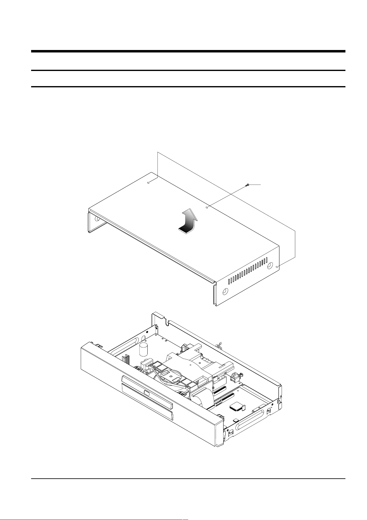
2-1-1 Top Cabinet Removal
1) Remove 3 Screws Πon the back Top Cabinet.
2) Lift up the Top Cabinet in direction of arrow.
Π3 SCREWS
Fig. 2-1 Top Cabinet Removal
Note : Reassembly in reverse order.
2-2
Samsung Electronics
Disassembly and Reaasembly
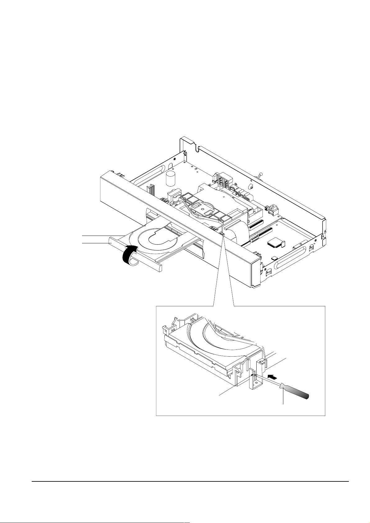
2-1-2 Door-Tray Removal
1) Supply power and open Tray Œ.
2) Disassemble the Door-Tray ´ in direction of arrow “A”.
3) Close Tray Πand power off.
Note : If Tray Œ doesn’t open, insert a Screw driver ¨ into the Emergency hole ˇ (as shown in detailed draw-
ing) and then push it in the direction of arrow “B”. Open Tray manually.
ΠTRAY
´ DOOR-TRAY
"A"
<Side View>
ˇ EMERGENCY HOLE
¨ SCREW DRIVER
"B"
Fig. 2-2 Door-Tray Removal
Disassembly and Reaasembly
Samsung Electronics
2-3
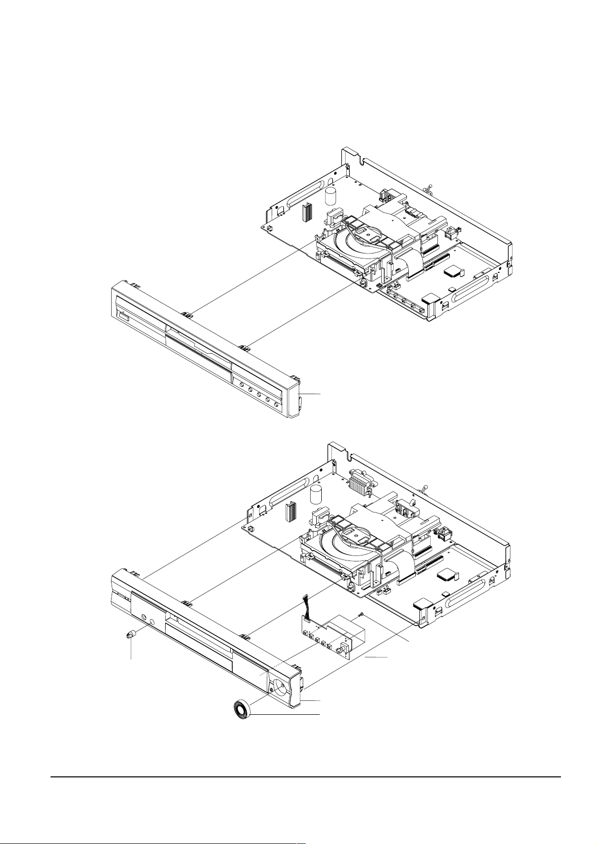
´ ASS'Y FRONT-CABINET
´ ASS'Y FRONT-CABINET
ˆ KEY PCB
¨ 5 SCREWS
ˇ KNOB-JOG
ΠKNOB-VOLUME
<DVD-M10x SERIES/DVD-M20x SERIES MODELS>
<DVD-M30x SERIES/DVD-M40x SERIES MODELS>
Fig. 2-3 Ass’y Front-Cabinet Removal
2-1-3 Ass’y Front-Cabinet Removal
1) Remove Knob-Volume Œ and Ass’y Front-Cabinet ´.
2) Remove Knob-Jog ˇ and 5 Screws ¨ and Key PCB ˆ.
2-4
Samsung Electronics
Disassembly and Reaasembly
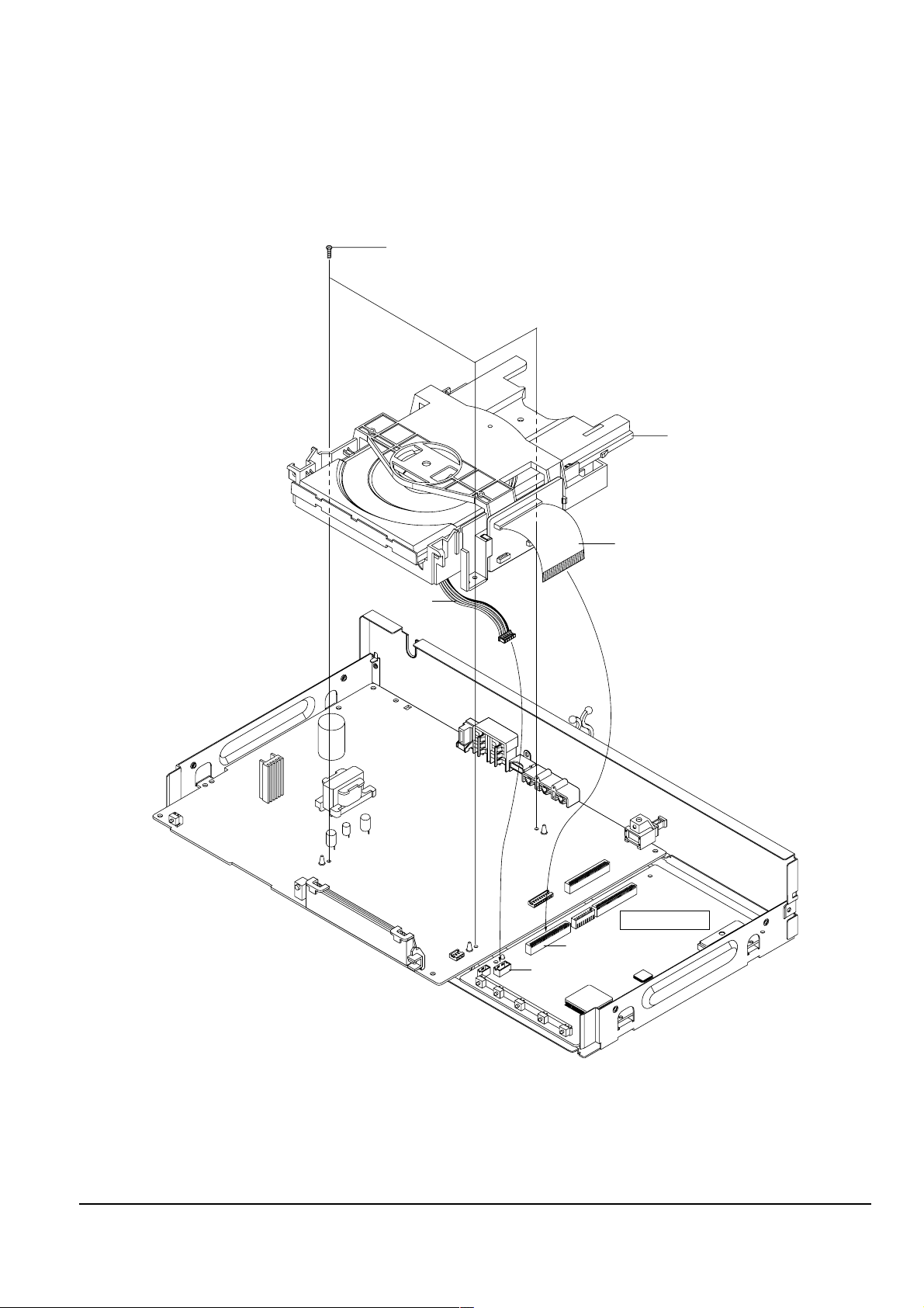
DECK-ASS'Y
Π3 SCREWS
DCN1
MAIN PCB
FLAT-CABLE
CONNECT-WIRE
DCN2
2-1-4 Ass’y Deck Removal
1) Disconnect Flat-Cable,Connect-Wire from DCN1, DCN2 on Main PCB.
2) Remove 3 Screws Œ from the Ass’y Deck and lift it up.
Fig. 2-4 Ass’y Deck Removal
Disassembly and Reaasembly
Samsung Electronics
2-5
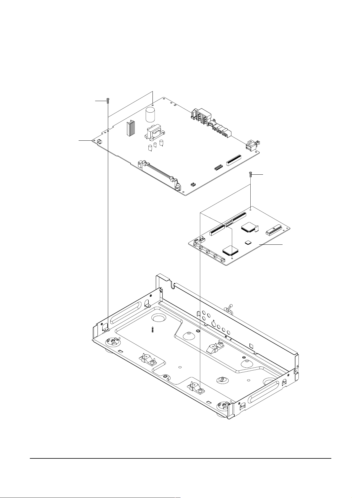
¨ MAIN PCB
ˇ 3 SCREWS
Π2 SCREWS
´ JACK PCB
Fig. 2-5 Main PCB, Jack PCB Removal
2-1-5 Main PCB, Jack PCB Removal
1) Remove 2 Screws Œ and lift up the Jack PCB ´.
2) Remove 3 Screws ˇ and lift up the Main PCB ¨.
 Loading...