

Samsung DVD-518 Disassemble

Samsung Electronics
4-1
4. Disassembly and Reassembly
4-1 Cabinet and PCB
4-1-1 Top Cabinet Removal
1) Remove 3 Screws Πon the back Top Cabinet.
2) Remove 2 Screws ´, ˇ on the left and right side.
3) Lift up the Top Cabinet in direction of arrow.
Π3 SCREWS
´ 1 SCREW
ˇ 1 SCREW
Fig. 4-1 Top Cabinet Removal
Note : Reassembly in reverse order.
4-2
Samsung Electronics
Disassembly and Reaasembly
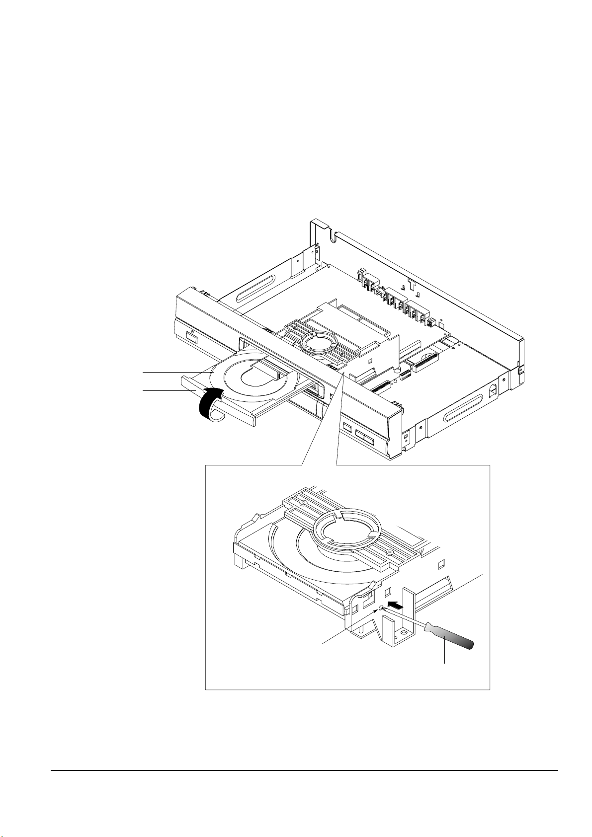
4-1-2 Door-Tray Removal
1) Supply power and open Tray Œ.
2) Disassemble the Door-Tray ´ in direction of arrow “A”.
3) Close Tray Πand power off.
Note : If Tray Œ doesn’t open, insert a Screw driver ¨ into the Emergency hole ˇ (as shown in detailed draw-
ing) and then push it in the direction of arrow “B”. Open Tray manually.
ˇ EMERGENCY HOLE
<Side View>
¨ SCREW DRIVER
"B"
ΠTRAY
´ DOOR-TRAY
"A"
Fig. 4-2 Door-Tray Removal

Disassembly and Reaasembly
Samsung Electronics
4-3
´ 5 SCREWS
ˇ KEY PCB
ΠASS'Y FRONT-PANEL
Fig. 4-3 Ass’y Front-Panel, Key PCB Removal
4-1-3 Ass’y Front-Panel, Key PCB Removal
1) Remove Ass’y Front-Panel Œ.
2) Remove 5 Screws ´ and Key PCB ˇ.
4-4
Samsung Electronics
Disassembly and Reaasembly
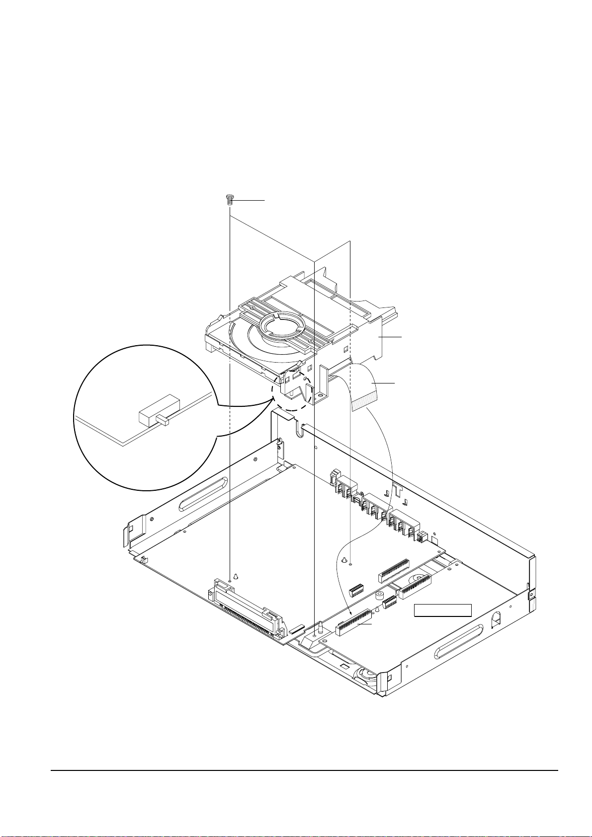
DECK-ASS'Y
Π3 SCREWS
DCN1
MAIN PCB
SW3
OFF
ON
FLAT-CABLE
4-1-4 Ass’y Deck Removal
1) Remove 4 Screws Œ from the Ass’y Deck and lift it up.
CAUTIONS ;
(1) When disassembling, switch the SW3 to “OFF” on the Deck PCB and remove the Flat-Cable connected to DCN1 on Main PCB.
(2) When assembling, insert the Flat-Cable into the DCN1 on Main PCB and switch SW3 to “ON” on the Deck PCB.
Fig. 4-4 Ass’y Deck Removal
Disassembly and Reaasembly
Samsung Electronics
4-5
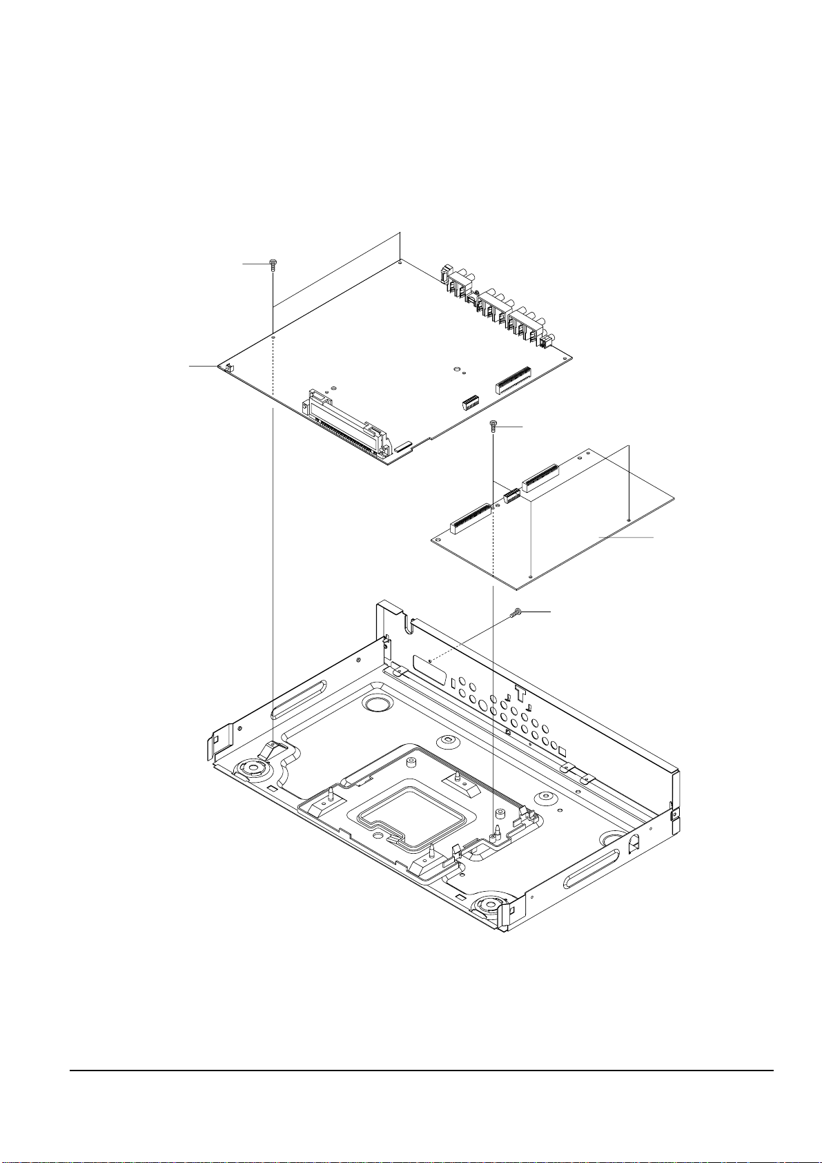
´ 2 SCREWS
ˇ JACK PCB
ˆ MAIN PCB
¨ 3 SCREWS
Π1 SCREW
; (SCART JACK MODEL ONLY)
Fig. 4-5 Main PCB, Jack PCB Removal
4-1-5 Main PCB, Jack PCB Removal
1) Remove 1 Screw Œ.
2) Remove 2 Screws ´ and lift up the Jack PCB ˇ.
3) Remove 3 Screws ¨ and lift up the Main PCB ˆ.
 Loading...