How it Works
Log In / Sign Up
Buy Points
How it Works
FAQ
Contact Us
Questions and Suggestions
Users
Samsung
Loading...
D
DV448AEW-02555B-05
DV448AEW/XAA-00
DV448AEW/XAA-01
DV448AEW/XAA-02
DV448AEW/XAA-03
DV448AG
DV448AGP
3
DV448AGP/XAA-00
DV448AGP/XAA-01
DV448AGP/XAA-02
DV448AGW
DV448AGW/XAA-00
DV448AGW/XAA-01
DV448AGW/XAA-02
DV455
DV455EVGSGR
2
DV455EVGSGRAA
DV455EVGSGR/AA-01
DV455EVGSWR
DV455EVGSWRAA
DV455EVGSWR/AA-00
DV455EVGSWR/AA-01
DV455EVGSWR/AA-02
DV455GVGSGR
2
DV455GVGSGR-AA
2
DV455GVGSGR/AA-01
DV455GVGSWR
DV455GVGSWRAA
DV456
DV456ETHDSU-AA
DV456ETHDSU/AA-00
DV456ETHDSU/AC
DV456EWHDSU
DV456EWHDSU/AA
2
DV456EWHDSU/AA-00
DV456EWHDSU/AA-01
DV456EWHDSU/AC
DV456EWHDWR
2
DV456EWHDWRAA
2
DV456EWHDWR/AA-01
DV456GTHDSU/AA
DV456GWHDSU
2
DV456GWHDSU/AA
2
DV456GWHDSU/AA-00
DV456GWHDSU/AA-01
DV456GWHDWR
DV456GWHDWRAA
2
DV456GWHDWR/AA-01
DV457
DV457E1GSGR-A1
DV457EVGSGR
2
DV457EVGSGR-A1
DV457EVGSGRAA
DV457EVGSWR
DV457EVGSWR-AA
DV457GVGSGR
DV457GVGSGRAA
2
DV457GVGSWR
DV457GVGSWR/AA
2
DV457GVGSWR/AA-00
DV457GVGSWR/AA-01
DV457GVGSWR/AA-02
DV45H6300EG-A3
DV45H6300EG/A3-00
DV45H6300EW/A3
DV45H6300EW/A3-00
DV45H6300GG
DV45H6300GG/A3
DV45H6300GG/A3-00
DV45H6300GW/A3
DV45H6300GW/A3-00
DV45H7000EP
DV45H7000EP/A3-00
DV45H7000EP/A3-01
DV45H7000EW
4
DV45H7000EW-A2
DV45H7000EW/A2-00
DV45H7000EW/A2-01
DV45H7000EW/A2-02
DV45H7000GP
2
DV45H7000GW
5
DV45H7000GW/A2
DV45H7000GW/A2-00
DV45H7000GW/A2-01
DV45H7000GW/A2-02
DV45H7200EW-A2
2
DV45H7200EW/A2-00
DV45H7200GW
DV45H7200GW/A2
DV45H7200GW/A2-00
DV45K6200E
DV45K6200EW/A3
DV45K6200EW/A3-00
DV45K6200EZ/A3
DV45K6200EZ/A3-00
DV45K6200GW/A3
DV45K6200GW/A3-00
DV45K6200GZ/A3
DV45K6200GZ/A3-00
DV45K6500E
Loading...
Loading...
Nothing found
DV457EVGSGR
User Manual
42 pgs
2.85 Mb
0
User Manual
216 pgs
6.75 Mb
0
Table of contents
Loading...
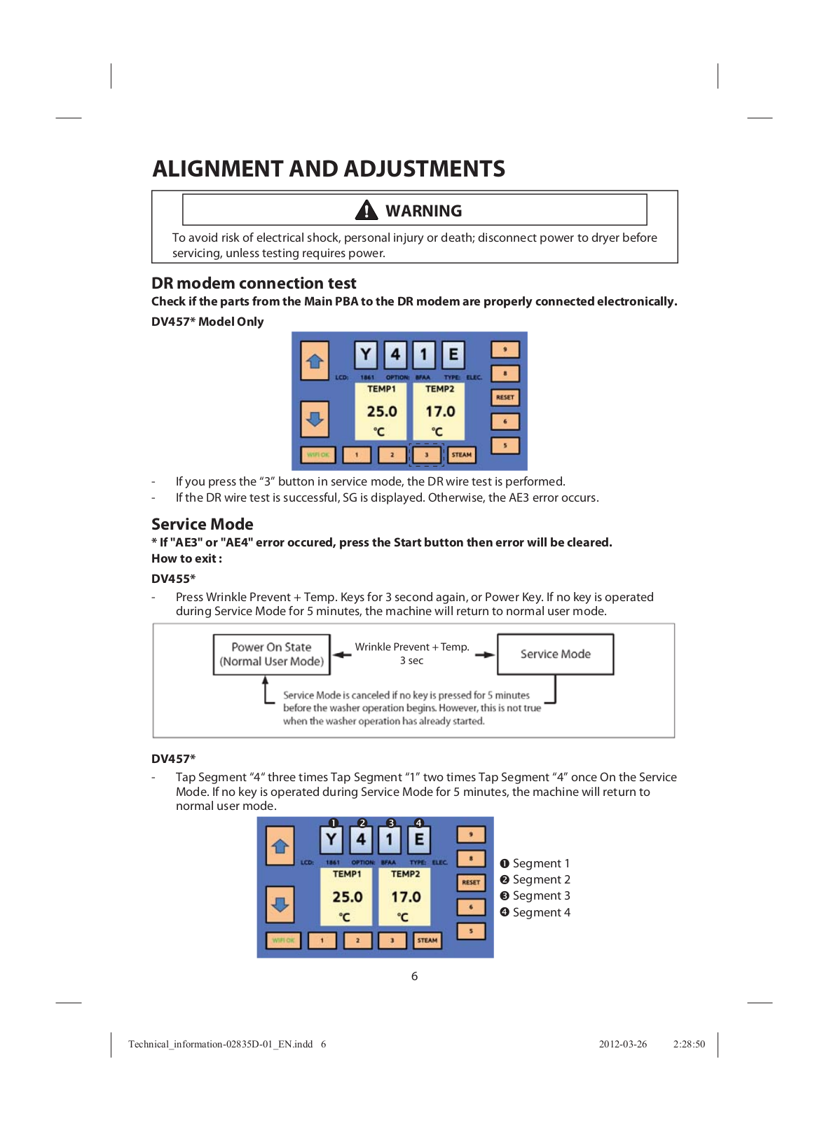
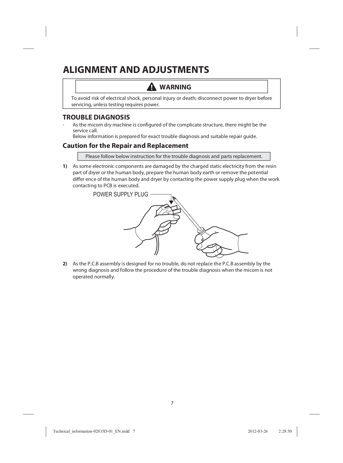
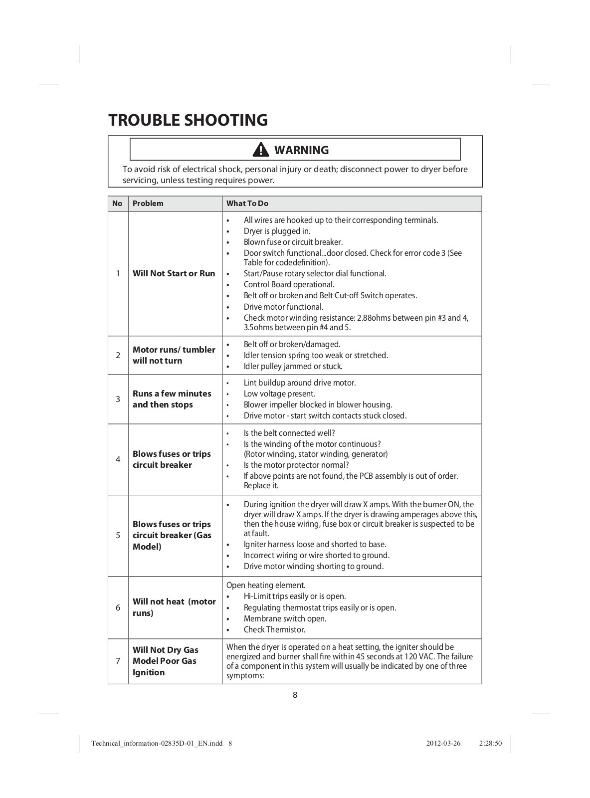
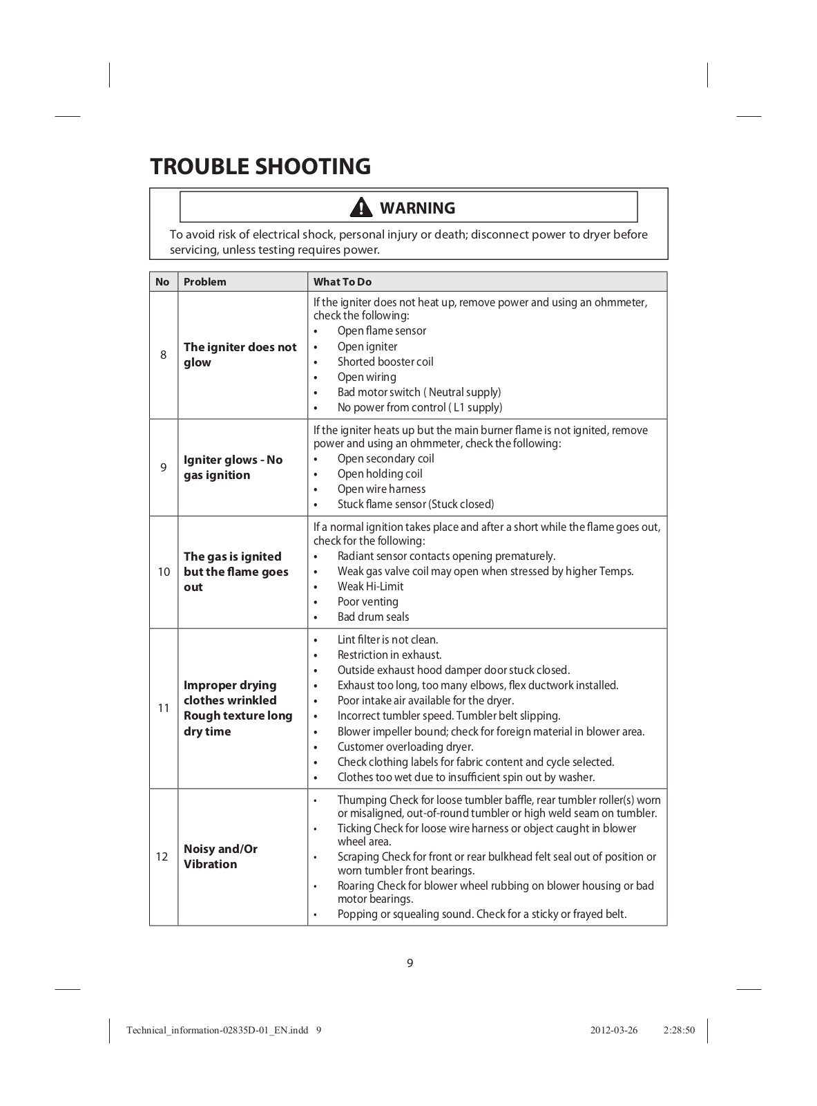
Samsung DV457EVGSGR User Manual
...
Samsung User Manual
Download
Specifications and Main Features
Frequently Asked Questions
User Manual
Download
Loading...
+
29
hidden pages
Unhide
You need points to download manuals.
1 point = 1 manual.
You can buy points or you can get point for every manual you upload.
Buy points
Upload your manuals
 Loading...