

Page 1
www.wnc.com.tw
User manual
Product description: IEEE 802.11g/n 1x1 USB module
WNC model name: DNUR-S1
Samsung model name: DNURS1
Version:
V1.0
Networking Product Center
Wistron Neweb
20 Park Avenue II, Hsinchu Science Park, Hsinchu 308, Taiwan, R.O.C.
Tel: +886-3-666-7799
Fax:+886-3-666-7711
Corporation
Subject to change without notices
© Copyrights 2011 by Wistron Neweb
All rights reserved
DNUB-S1 delivery specification
Page 2

1. Introduction
DNUR-S1 is an USB embedded module compliant with IEEE802.11n Draft 2.0 standard. The
core chipset is from Ralink, part number RT5370.
2. Features
CMOS Technology with PA, LNA, RF, Baseband, and MAC integrated.
1T1R Mode with 150Mbps PHY Rate for Both TX & RX.
20MHz Bandwidth
Reverse Direction Grant Data Flow and Frame Aggregation
WEP 64/128, WPA, WP A2, TKIP, AES, WAPI
QoS-WMM, WMM-PS
WPS, PIN, PBC
Multiple BSSID Support
www.wnc.com.tw
USB 2.0
Cisco CCX Support
Bluetooth Co-existence
Operating Systems – Windows XP 32/64, 2000, Windows 7, Vista 32/64, Linux, Macintosh
DNUB-S1 delivery specification
Page 3
www.wnc.com.tw
www.wnc.com.tw
3. Hardware Architecture:
3.1 Main Chipset Information
Item Vender Part number
MAC/BBP/Radio Transceiver/PA Ralink R T5370
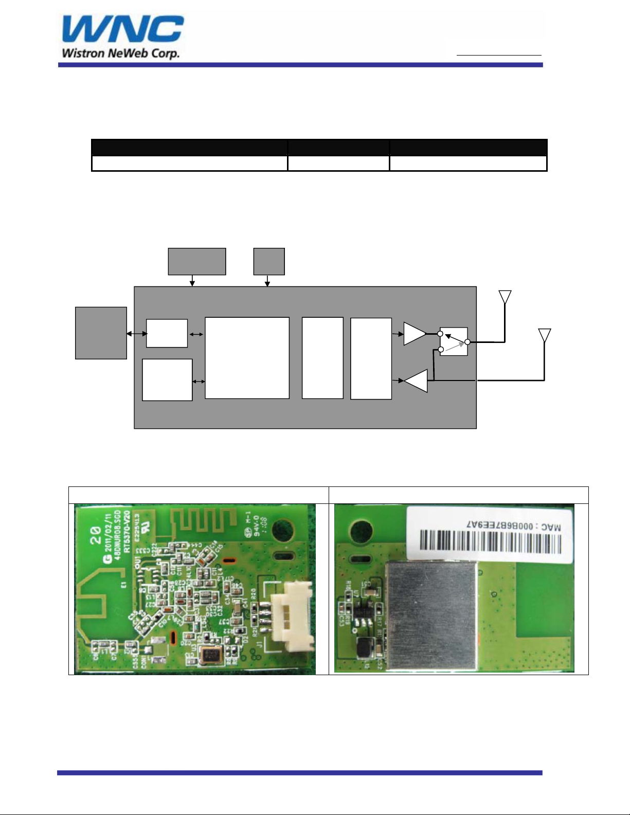
3.2 Circuit Block Diagram
The major internal components and external interfaces of DNUR-S1 are illustrated in Figure 1-1.
USB
connector
Regulator
USB
2.0
System
Control
Dc-Dc
Draft 802.11n
Packet Buffer/
Encrption Engi ne
Figure 1-1 DNUR-S1 Major Component and System Interface
MAC/
Xtal
Draft-
802.11n
PHY
Radio
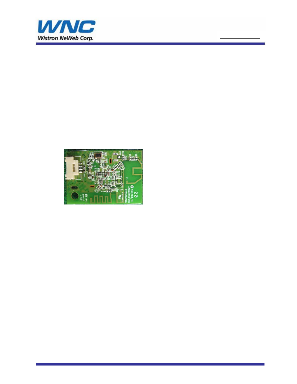
3.3 Outlook Diagram
Top View Bottom View
MAINANT(TX&RX)
PCBtraceantenna
RT5370
AUXANT(RXonly)
PCBtraceantenna
DNUR-S1
Page 4
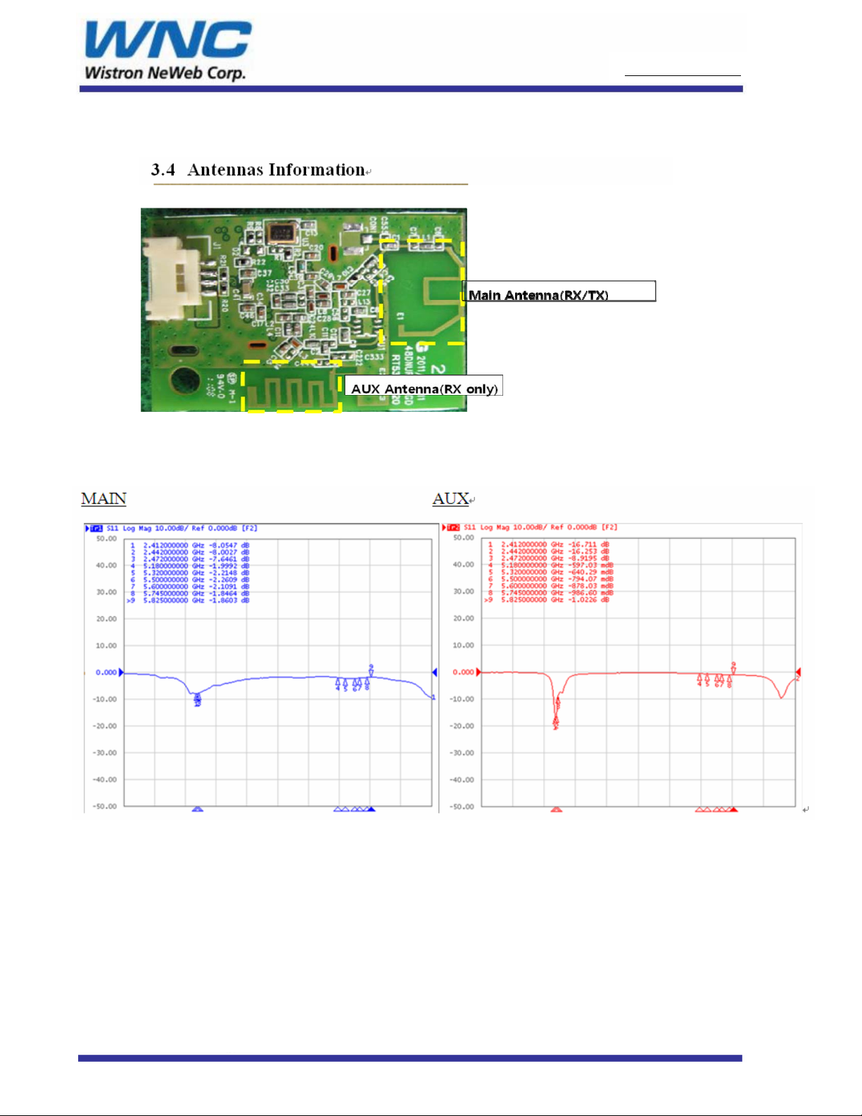
3.4 Antennas Information
3.4..1 VSWR
www.wnc.com.tw
www.wnc.com.tw
3.4..2Notice
No other antennas other than the on-board trace antenna are permitted for use with
this device(DNUR-S1).
DNUR-S1
Page 5
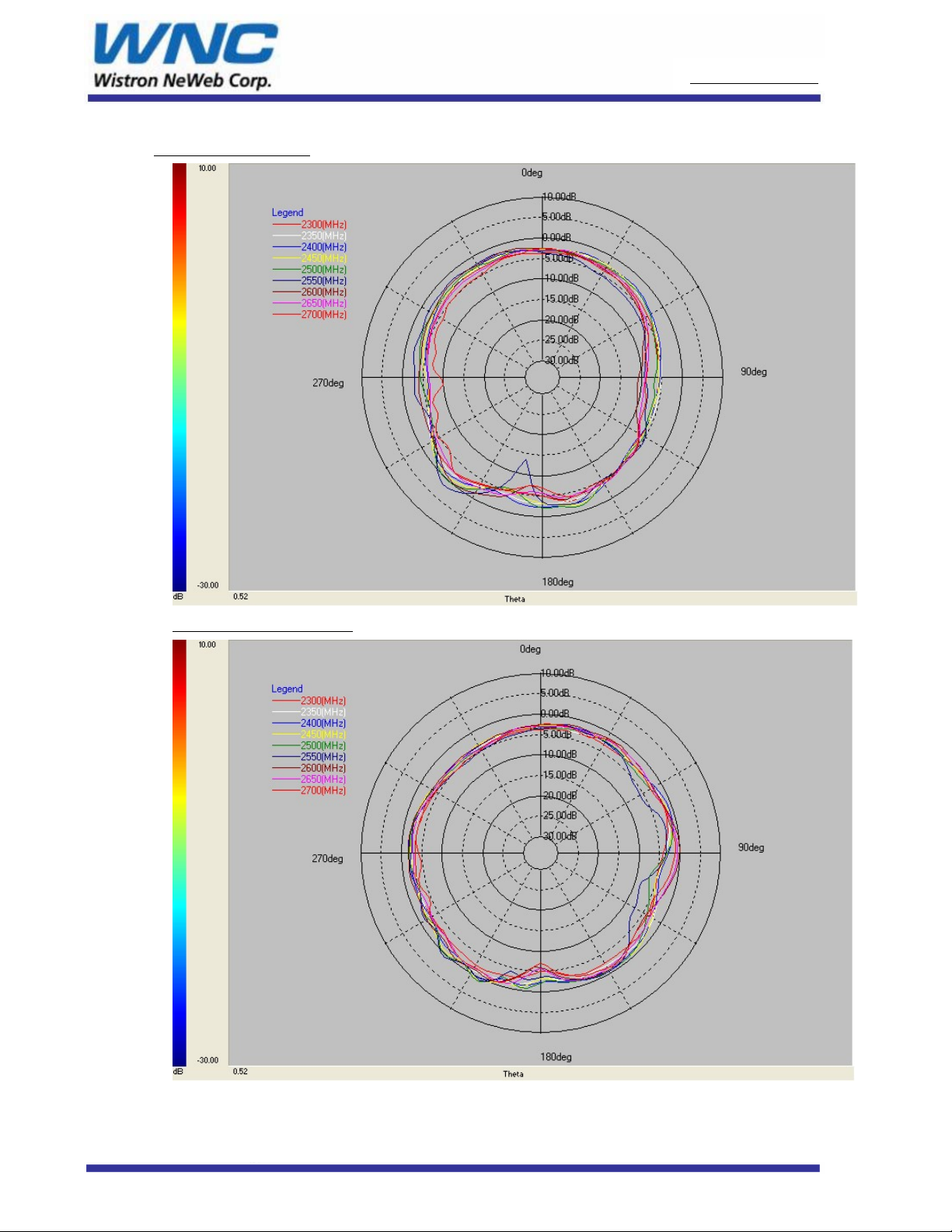
3.4.2 Antenna Pattern
www.wnc.com.tw
www.wnc.com.tw
XZ-Cut (Main ANT)
YZ-Cut (MAIN ANT )
DNUR-S1
Page 6

XZ-Cut (AUX ANT )
www.wnc.com.tw
www.wnc.com.tw
YZ-Cut (AUX ANT )
DNUR-S1
Page 7

www.wnc.com.tw
www.wnc.com.tw
3.4.3 Efficiency
3.4.4 Gain Table
DNUR-S1
Page 8

4. Interface definition
www.wnc.com.tw
www.wnc.com.tw
DNUR-S1
Page 9

5. Specifications:
5.1 Supply Voltage:
5V±5% DC
5.2 Current Consumption
www.wnc.com.tw
www.wnc.com.tw
5.3 RF power
Notes: Power level for different country domains is country dependent and Broadcom driver
& SPROM will control the regulatory power table. Therefore, the actual power may be lower
DNUR-S1
Page 10

than this number.
5.4 RF Sensitivity
www.wnc.com.tw
www.wnc.com.tw
5.5 Environmental Spec.
Operating Temperature Range: 0degree C~ 60degree C
Storage Temperature Range: Temperature: -20~80℃ Humidity: 95%(MAX)
Operating Humidity Range: 10%~90% (No dew condensation)
DNUR-S1
Page 11

www.wnc.com.tw
www.wnc.com.tw
6. Regulatory Notice
6.1 Information for US Users (FCC Notice)
FCC ID : A3LDNURS1
In accordance with FCC Part 15, the A3LDNURS1 is listed as a Modular Transmitter device. End products that include the
A3LDNURS1 shall have the words “Contains Transmitter module FCC ID: A3LDNURS1” on an exterior label
This device complies with Part 15 of FCC Rules. Operation is Subject to following two conditions:
(1) This device may not cause harmful interference, and
(2) This device must accept any interference received including interference that cause undesired operation.
This equipment has been tested and found to comply within the limits for a Class B digital device,
pursuant to part 15 of the FCC Rules. The se limits are desi gned to provi de reasonable prot ection against harm ful interference i n a
residential installation.
This equipment generates, uses, and can radiate radio frequency energy and, if not installed and used in accordance with the
instructions, may cause harmful interference to radio communications. However, there is no guarantee that interference will not
occur in a particular installation. If this equipment does cause harmful interference to radio or television reception, which can be
determined by turning the equipment off and on, the user is encouraged to try to correct the interference by one or more of the
following measures:
• Reorient or relocate the receiving antenna
• Increase the separation between the equipment and receiver
• Connect the equipment into an outlet on a different circuit from that to wh ich the receiver is
connected
• Consult the dealer or an experienced radio/TV technician for help.
The transmitter must not be co-located or operated in conjunction wit any other antenna or transmitter.
The available scientific evidence does not show that any health problems are associated with using low power wireless devices.
There is no proof, however, that these low power wireless devices are absolutely safe. Low power wireless devices emit low
levels of radio frequency energy (RF) in the microwave range while being used. Whereas high levels of RF can produce health
effects (by heating tissue), exposure to low-level RF that does not produce heating effects causes no known adverse health effects.
Many studies of low-level RF exposure s have not f ound any biol ogical effects. Som e studies have su ggested that som e biological
effects might occur, but such findings have not been confirmed by additional research.
To satisfy RF exposure requirements, this device and its antenna(s) must operate with a separation
distance of at least 20 centimeters from all persons and must not be co-located or operated in conjunction with any other antenna
or transmitter. End-users must be provided with specific operating instructions for satisfying RF exposure.
FCC WARNING:
Changes or modifications not expressly approved by the party responsible for compliance could void the user’s authority to
operate the equipment.
DNUR-S1
Page 12

www.wnc.com.tw
www.wnc.com.tw
6.2 Information for Canadian Users (IC Notice)
IC : 649E-DNURS1
The term “IC” before the radio certification number only signifies that Industry Canada technical
specifications were met. Operation is subject to the following two conditions: (1) this device may not
cause interference, and (2) this device must accept any interference, including interference that may
cause undesired operation of the device.
This Class B digital apparatus complies with Canadian ICES-003.
To prevent radio interference to the licensed service, this device is intended to be operated indoors and away from windows to
provide maximum shielding. Equipment that is installed outdoors is subject to licensing.
This device has been designed to operate with an antenna having a maximum gain of 0.6dB. Antennas
having a higher gain are strictly prohibited per regulations of Industry Canada. The required antenna
impedance is 50 ohms.
To reduce potential radio interference to others, the antenna type and its gain should be so chosen that the equi valent isot ropically
radiated power (EIRP) is not more than required for successful communication.
The available scientific evidence does not show that any health problems are associated with using low power wireless devices.
There is no proof, however, that these low power wireless devices are absolutely safe. Low power wireless devices emit low
levels of radio frequency energy (RF) in the microwave range while being used. Whereas high levels of RF can produce health
effects (by heating tissue), exposure to low-level RF that does not produce heating effects causes no known adverse health effects.
Many studies of low-level RF exposures have not found any biological effects. Some studies have suggested that some biological
effects might occur, but such findings have not been confirmed by addition
DNUR-S1
Page 13

www.wnc.com.tw
www.wnc.com.tw
7. Installation
This radio module must be installed in a device and not allow the user to replace nor modify it. Besides, it
was under FCC modular approval, therefore there are some rules need to follow while adopting this
module :
1. Include content “FCC ID : A3LDNURS1” on the label of your device.
2. Use the on-board trace antenna (refer to the spec in this document ).
7.1 Installation Procedure
1. Be sure to use the proper antistatic handling techniques.
2. Insert the DNURS1 into the machine and fix it by bracket.
Side view
DNUR-S1
Page 14

TOP view
www.wnc.com.tw
www.wnc.com.tw
DNUR-S1
 Loading...