

User manual
Product description: IEEE 802.11g/n 2x2 USB module
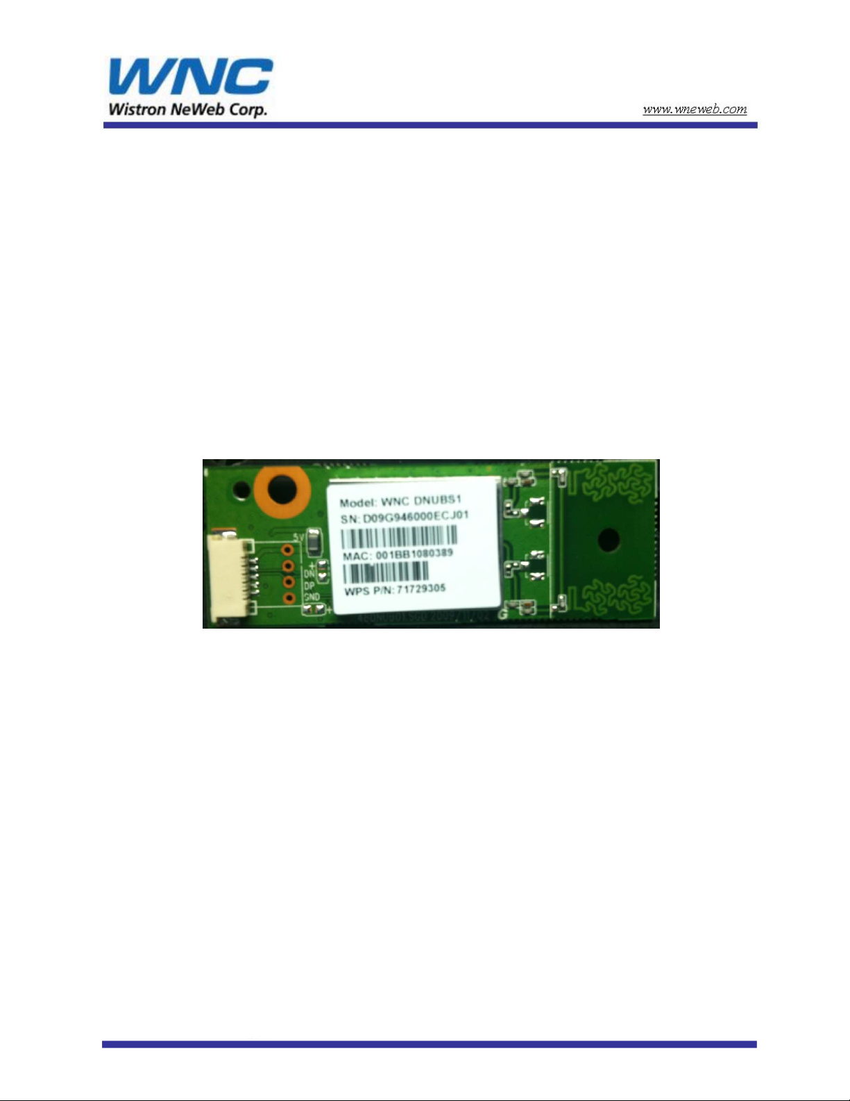
WNC model name: DNUB-S1
Samsung model name: DNUBS1
Version:
Networking Product Center
V2.0
Wistron Neweb® Corporation
No. 10-1, Lin-hsin I Road, Science-Based Industry Park, Hsinchu 300, Taiwan, R.O.C.
Tel: +886-3-666-7799
Fax:+886-3-666-7711
Subject to change without notices
© Copyrights 2009 by Wistron Neweb
All rights reserved
DNUB-S1 delivery specification
®

1. Introduction
DNUB-S1 is a USB embedded module compliant with IEEE802.11n Draft 2.0 standard. The core
chipset is from Broadcom, part number BCM43231.
2. Features
2x2 MIMO technology
Data rates up to 130Mbps for 20MHz channels and 300Mbps for 40MHz channels
Designs meet Pb-free/RoHS worldwide requirements
Integrated ARM® Cortex-M3™ CPU and on-chip RAM for USB host offload
Single driver across platforms simplifies driver update process and improves customer
satisfaction
WPA™/WPA2™
Cisco® Compatible Extensions (CCXv4, CCXv5)
Full-rate AES engine in hardware
WMM® for quality of service
Integrated 2.4G Power Amplifier (BCM43231) provides path to lower solution cost for
single-band designs
Support for Windows® XP, Windows Vista®, and Linux® Operating Systems
USB AP functionality provides 802.11n dual-band upgrade path to legacy routers and gateways
LED reserved for special application.
DNUB-S1 delivery specification

3. Hardware Architectur e:
3.1 Main Chipset Information
Item Vender Part number
MAC/BBP/Radio Transceiver/PA Broadcom BCM43231
3.2 Circuit Block Diagram
The major internal components and external interfaces of DNUB-S1 are illustrated in Figure 1-1.
JTAG
Internal Bus
USB
2.0
GPIO
Figure 1-1 DNUB-S1 Major Component and System Interface
3.3 Outlook Diagram
Top view
Fix hole for screw
ARM
Dra ft 802.11n
ROM
RAM
MAC
Securuty
SPROM I/F
Draft-
802.11n
PHY
2x2
Radio
BCM43231
Antenna 0
Fix hole for plastic screw
(Metal screw will impact the antenna
performance)
Antenna 1
LED option (default was removed)
Two options for USB connector ( FPC & cable)
DNUB-S1

Bottom view
3.4 Antennas Information
Two trace antennas supporting both TX & RX.
ANT 1
ANT 0
3.4..1 VSWR
DNUB-S1

3.4.2 Antenna Pattern
DNUB-S1

3.4.3 Efficiency
The efficiency is 35%.
3.4.4 Gain Table
MHz
XY plan XZ pl an Y Z p l an
2400 -3.03 -0.09 -1.32
2450 -2.15 0.23 -0.58
2500 -1.89 0.6 0.33
4. Interface definition
Peak gai n ( dB i )
GND
GND
D+
DVCC
DNUB-S1

USB FPC Cable & connector
DNUB-S1

5. Mechanical drawing
5.1 Dimension
DNUB-S1

6. Specifications:
6.1 Supply Voltage:
5V±5% DC
6.2 Current Consumttion
11b TX mode@16dBm
11g TX mode@15dBm
11b Throughput . Tx
11g Throughput . Tx
Associated and idle with power saving
HT20 Tx MCS8
HT20 Tx MCS15
HT40 Tx MCS8 580
HT40 Tx MCS15
(Typical level, with +/- 50mA tolerance)
6.3 RF power
(Typical power level per chain with +/- 2.5 dB tolerance ) ( unit:dBm )
20MHz BW
1Mbps
2Mbps
5.5Mbps
11Mbps
6Mbps
9Mbps
12Mbps
18Mbps
24Mbps
36Mbps
48Mbps
54Mbps
HT20MCS0
HT20MCS1
HT20MCS2
HT20MCS3
HT20MCS4
HT20MCS5
HT20MCS6
HT20MCS7
Condition
5V supply only
Unit
Peak
265
260
400
390
170
420
390
550
mA
MHz
2412 2437 2472 2412 2437 2472
16 16 16
16 16 16
16 16 16
16 16 16
15 15 15
15 15 15
15 15 15
15 15 15
15 15 15
15 15 15
15 15 15
15 15 15
13.5 13.5 13.5
13.5 13.5 13.5
13.5 13.5 13.5
13.5 13.5 13.5
13.5 13.5 13.5
13.5 13.5 13.5
13.5 13.5 13.5
13.5 13.5 13.5
40MHz BW
HT40MCS0
HT40MCS1
HT40MCS2
HT40MCS3
HT40MCS4
HT40MCS5
HT40MCS6
HT40MCS7
13.5 13.5 13.5
13.5 13.5 13.5
13.5 13.5 13.5
13.5 13.5 13.5
13.5 13.5 13.5
13.5 13.5 13.5
13.5 13.5 13.5
13.5 13.5 13.5
MHz
`
DNUB-S1

Notes: Power level for different country domains is country dependent and Broadcom driver
& SPROM will control the regulatory power table. Therefore, the actual power may be lower
than this number.
6.4 RF Sensitivity
(Typical sensitivity level, 2RX with +3/- 6 dB tolerance) ( unit:dBm )
20MHz BW
1Mbps
2Mbps
5.5Mbps
11Mbps
6Mbps
9Mbps
12Mbps
18Mbps
24Mbps
36Mbps
48Mbps
54Mbps
HT20 MCS0
HT20 MCS1
HT20 MCS2
HT20 MCS3
HT20 MCS4
HT20 MCS5
HT20 MCS6
HT20 MCS7
MHz
2412 2442 2472 2412 2442 2472
-98 -98 -98
-96 -96 -96
-93 -93 -93
-89 -89 -89
-91 -91 -91
-90 -90 -90
-89 -89 -89
-88 -88 -88
-86 -86 -86
-83 -83 -83
-77 -77 -77
-76 -76 -76
-92 -92 -92
-91 -91 -91
-90 -90 -90
-85 -85 -85
-83 -83 -83
-77 -77 -77
-76 -76 -76
-74 -74 -74
40MHz BW
HT40 MCS0
HT40 MCS1
HT40 MCS2
HT40 MCS3
HT40 MCS4
HT40 MCS5
HT40 MCS6
HT40 MCS7
-89 -89 -89
-88 -88 -88
-86 -86 -86
-82 -82 -82
-80 -80 -80
-74 -74 -74
-73 -73 -73
-71 -71 -71
MHz
6.5 Environmental Spec.
Operating Temperature Range: 0degree C~ 60degree C
Storage Temperature Range: Temperature: -20~80℃ Humidity: 95%(MAX)
Operating Humidity Range: 10%~90% (No dew condensation)
DNUB-S1

7. NOTICE
FCC ID: A3LDNUBS1
NOTICE
In accordance with FCC Part 15, the A3LDNUBS1 is listed as a Modular Transmitter device. End products that
include the A3LDNUBS1 shall have the words “Contains Transmitter module FCC ID: A3LDNUBS1” on an
exterior label
l.
This device complies with Part 15 of F CC Rules. Operation is Subject to following two conditions:
(1) This device may not cause harmful interference, and
(2) This device must accept any interference received including interference that cause undesired
operation.
This equipment has been tested and found to comply within the limits for a Class B digital device,
pursuant to part 15 of the FCC Rules. These limits are designed to provide reasonable protection against
harmful interference in a residential installation.
This equipment generates, uses, and can radiate radio frequency energy and, if not installed and used in
accordance with the instructions, may cause harmful interference to radio communications. However, there is
no guarantee that interference will not occur in a particular installation. If this equipment does cause harmful
interference to radio or television reception, which can be determined by turning the equipment off and on, the
user is encouraged to try to correct the interference by one or more of the following measures:
• Reorient or relocate the receiving antenna
• Increase the separation between the equipment and receiver
• Connect the equipment into an outlet on a different circuit from that to which the receiver is
connected
• Consult the dealer or an experienced radio/TV technician for help.
The transmitter must not be co-located or operated in conjunction wit any other antenna or transmitter.
The available scientific evidence does not show that any health problems are associated with using low power
wireless devices. There is no proof, however, that these low power wireless devices are absolutely safe. Low
power wireless devices emit low levels of radio frequency energy (RF) in the microwave range while being
used. Whereas high levels of RF can produce health effects (by heating tissue), exposure to low-level RF that
does not produce heating effects causes no known adverse health effects. Many studies of low-level RF
exposures have not found any biological effects. Some studies have suggested that some biological effects
might occur, but such findings have not been confirmed by additional research.
To satisfy RF exposure requirements, this device and its antenna(s) must operate with a separation
distance of at least 20 centimeters from all persons and must not be co-located or operated in conjunction with
any other antenna or transmitter. End-users must be provided with specific operating instructions for satisfying
RF exposure.
FCC WARNING:
Changes or modifications not expressly approved by the party responsible for compliance could void the
user’s authority to operate the equipment.

Information for Canadian Users (IC Notice)
IC : 649E-DNUBS1
The term “IC” before the radio certification number only signifies that Industry Canada technical
specifications were met. Operation is subject to the following two conditions: (1) this device may not
cause interference, and (2) this device must accept any interference, including interference that may
cause undesired operation of the device.
This Class B digital apparatus complies with Canadian ICES-003.
T
o prevent radio interference to the licensed service, this device is intended to be operated indoors and away
from windows to provide maximum shielding. Equipment that is installed outdoors is subject to licensing.
This device has been designed to operate with an antenna having a maximum gain of 0.6dB. Antennas
having a higher gain are strictly prohibited per regulations of Industry Canada. The required antenna
impedance is 50 ohms.
To reduce potential radio interference to others, the antenna type and its gain should be so chosen that the
equivalent isotropically radiated power (EIRP) is not more than required for successful communication.
The available scientific evidence does not show that any health problems are associated with using low power
wireless devices. There is no proof, however, that these low power wireless devices are absolutely safe. Low
power wireless devices emit low levels of radio frequency energy (RF) in the microwave range while being
used. Whereas high levels of RF can produce health effects (by heating tissue), exposure to low-level RF that
does not produce heating effects causes no known adverse health effects. Many studies of low-level RF
exposures have not found any biological effects. Some studies have suggested that some biological effects
might occur, but such findings have not been confirmed by addition
ʳ8. Installation
This radio module must be installed in a device and not allow the user to replace nor modify it.. Besides,
it was under FCC modular approval, therefore there are some rules need to follow while adopting this
module :
1. Include content “FCC ID : A3LDNUBS1” on the label of your device.
2. Use the on-board trace antenna (refer to the spec in this document ).

8.1 Installation Procedure
1. Be sure to use the proper antistatic handling techniques
2. Insert the DNUBS1 into the machine and fix it by bracket.
 Loading...