

Page 1

User Manual
DM65E-BR DM75E-BR DM82E-BR
The colour and the appearance may differ depending on the product,
and the specifications are subject to change without prior notice to
improve the performance.
Page 2

Table of contents
Before Using the Product
Copyright 7
Safety Precautions 8
Symbols 8
Cleaning 8
Storage 9
Electricity and Safety 9
Installation 10
Operation 12
Precautions when handling the panel 15
Preparations
Checking the Components 16
Components 16
Parts 18
Control Panel 18
Parts 19
Control Panel 19
External sensor KIT 21
Reverse Side 22
Reverse Side 23
Tray 24
Installing the Tray 25
Using the touch function 26
Plug In Module (Sold separately) 27
Anti-theft Lock 27
Spacer logo 28
Remote Control 29
Connection Using an IR Stereo Cable (sold
separately) 31
Before Installing the Product
(Installation Guide) 32
Ventilation 32
Dimensions 33
Installing the Wall Mount 34
Preparing before installing Wall-Mount 34
Installing the Wall Mount 34
Wall Mount Kit Specifications (VESA) 35
Remote Control (RS232C) 36
Cable Connection 36
Connection 39
Control Codes 40
Connecting and Using a Source
Device
Before Connecting 49
Pre-connection Checkpoints 49
Connecting to a PC 49
Connection using the D-SUB cable
(Analogue type) 49
Connection using a DVI cable (Digital type) 50
Connection Using an HDMI-DVI Cable 50
Connection Using an HDMI Cable 51
Connection Using an DP Cable 51
Connecting to a Video Device 52
Connection Using the AV Cable 52
Connection Using the component Cable 52
Connection Using an HDMI-DVI Cable 53
Connection Using an HDMI Cable 54
Connecting to an Audio System 54
Connecting the LAN Cable 55
Changing the Input source 56
Source 56
Using MDC
MDC Programme Installation/Uninstallation 57
Installation 57
Uninstallation 57
Connecting to MDC 58
Using MDC via RS-232C
(serial data communications standards) 58
Using MDC via Ethernet 59
Home feature
Player 61
Approving a connected device from the server 62
Network Channel 66
Local Channel 66
My Templates 66
2
Page 3
Table of contents
Available features in the Player page 67
Player page Settings menu 68
When Content is Running 70
File Formats Compatible with Player 72
File Formats Compatible with Videowall 77
Schedule 79
Available features in the Schedule page 79
Template 81
Clone Product 84
ID Settings 85
Device ID 85
PC Connection Cable 85
Device ID Auto Set 85
Video Wall 86
Apply to 86
Video Wall 87
Network Status 88
Picture Mode 89
On/Off Timer 90
On Timer 90
Off Timer 91
Holiday Management 91
Ticker 92
More settings 92
URL Launcher 93
Screen Adjustment
Picture Mode 94
Backlight / Contrast / Brightness /
Sharpness / Colour / Tint (G/R)
Colour Temperature 96
White Balance 97
2 Point 97
10 Point 97
Gamma 98
Calibrated value 98
Advanced Settings 99
Dynamic Contrast 100
Black Tone 100
Flesh Tone 100
RGB Only Mode 100
Colour Space 100
Motion Lighting 100
Picture Options 101
Colour Tone 102
Digital Clean View 102
MPEG Noise Filter 102
HDMI Black Level 103
Film Mode 103
Motion Plus 104
Dynamic Backlight 104
Picture Size 105
Picture Size 105
95
Position 106
Zoom/Position 106
Resolution 107
Auto Adjustment 108
PC Screen Adjustment 108
Picture Off 109
Reset Picture 109
OnScreen Display
PIP 110
PIP Settings 110
Display Orientation 112
Onscreen Menu Orientation 112
Source Content Orientation 112
Aspect Ratio 112
Screen Protection 113
Auto Protection Time 113
Screen Burn Protection 113
Message Display 116
Source Info 116
No Signal Message 116
MDC Message 116
Download Status Message 116
Menu Language 117
Reset OnScreen Display 117
3
Page 4

Table of contents
Sound Adjustment
Sound Mode 118
Sound Effect 119
Virtual Surround 119
Dialog Clarity 119
Equaliser 119
HDMI Sound 120
Sound on Video Call 120
Dolby Digital Comp 121
Speaker Settings 121
Sound Output 121
Auto Volume 122
Reset Sound 122
Network
Network Status 123
Network Settings 123
Network type 123
Network Settings (Wired) 124
Network Setting (Wireless) 126
WPS(PBC) 128
Wi-Fi Direct 129
Multimedia Device Settings 129
Screen Mirroring 130
Screen Mirroring 130
Server Network Settings 130
Connect to server 130
MagicInfo Mode 130
Server Access 130
FTP Mode 130
Device Name 131
System
Accessibility 132
Menu Transparency 132
High Contrast 132
Enlarge 132
Setup 133
Initial settings (System) 133
Touch Control 135
Touch Control Lock 135
Admin Menu Lock 135
Device to Control 135
Time 136
Clock Set 136
DST 136
Sleep Timer 136
Power On Delay 136
Auto Source Switching 137
Auto Source Switching 137
Primary Source Recovery 137
Primary Source 137
Secondary Source 137
Power Control 138
Auto Power On 138
PC module power 138
Max. Power Saving 138
Standby Control 139
Power Button 139
Network Standby 139
Eco Solution 140
Energy Saving 140
Eco Sensor 140
Screen Lamp Schedule 140
No Signal Power Off 141
Auto Power Off 141
Temperature Control 141
Device Manager 142
Keyboard Settings 142
Mouse Settings 143
Pointer Settings 144
Play via 145
Change PIN 145
Security 146
Safety Lock 146
Button Lock 146
USB Auto Play Lock 146
Mobile Connection Lock 146
4
Page 5

Table of contents
General 147
Smart Security 147
BD Wise 148
Anynet+ (HDMI-CEC) 149
Troubleshooting for Anynet+ 151
HDMI Hot Plug 153
DivX® Video On Demand
Game Mode 153
Reset System 154
153
Support
Software Update 155
Update now 155
Auto update 155
Contact Samsung 155
Go to Home 156
Player 156
Schedule 156
Template 156
Clone Product 156
ID Settings 156
Video Wall 157
Network Status 157
Picture Mode 157
On/Off Timer 157
Ticker 157
More settings 157
Playing photos, videos and music
(Media Play)
Read the following before using
media play with a USB device 159
Using a USB device 161
Playing media content from a PC/mobile device 162
Features provided in the media
content list page 163
Menu items in the media content list page 164
Available buttons and features
during photo playback 165
Available buttons and features
during video playback 166
Available buttons and features
during music playback 167
Supported Subtitle and
Media play file formats 168
Subtitle 168
Supported image resolutions 168
Supported music file formats 169
Supported Video Formats 169
Troubleshooting Guide
Requirements Before Contacting Samsung
Customer Service Centre 171
Testing the Product 171
Checking the Resolution and Frequency 171
Check the followings. 172
Q & A 179
Specifications
General 181
PowerSaver 183
Preset Timing Modes 184
Reset All 158
5
Page 6

Table of contents
Appendix
Responsibility for the Pay Service
(Cost to Customers) 186
Not a product defect 186
A Product damage caused by customer's fault 186
Others 186
WEEE 187
Correct Disposal of This Product
(Waste Electrical & Electronic Equipment) 187
Correct disposal of batteries in this product 187
Optimum Picture Quality and
Afterimage Burn-in Prevention 188
Optimum Picture Quality 188
Prevention of Afterimage Burn-in 188
Licence 190
Terminology 191
6
Page 7

Chapter 01
Before Using the Product
Copyright
The contents of this manual are subject to change without notice to improve quality.
© 2015 Samsung Electronics
Samsung Electronics owns the copyright for this manual.
Use or reproduction of this manual in parts or entirety without the authorization of Samsung Electronics is prohibited.
Microsoft, Windows are registered trademarks of Microsoft Corporation.
VESA, DPM and DDC are registered trademarks of the Video Electronics Standards Association.
Ownership of all other trademarks is attributed to their due owner.
•
An administration fee may be charged if either
-
(a) an engineer is called out at your request and there is no defect in the product
(i.e. where you have failed to read this user manual).
-
(b) you bring the unit to a repair centre and there is no defect in the product
(i.e. where you have failed to read this user manual).
•
The amount of such administration charge will be advised to you before any work or home visit is carried out.
7
Page 8

Safety Precautions
Caution
RISK OF ELECTRIC SHOCK DO NOT OPEN
Caution : TO REDUCE THE RISK OF ELECTRIC SHOCK, DO NOT REMOVE COVER. (OR BACK)
THERE ARE NO USER SERVICEABLE PARTS INSIDE.
REFER ALL SERVICING TO QUALIFIED PERSONNEL.
This symbol indicates that high voltage is present inside.
It is dangerous to make any kind of contact with any internal part of this product.
This symbol alerts you that important literature concerning operation and maintenance has been
included with this product.
Symbols
Cleaning
―
Exercise care when cleaning as the panel and exterior of advanced LCDs are easily scratched.
―
Take the following steps when cleaning.
―
The following images are for reference only. Real-life situations may differ from what is shown in the
images.
Power off the product and computer.
1
Disconnect the power cord from the product.
2
―
Hold the power cable by the plug and do not touch the cable with wet
hands. Otherwise, an electric shock may result.
Wipe the product with a clean, soft and dry cloth.
3
•
Do not use detergents that contain alcohol, solvent or
surface-active agents.
!
•
Do not spray water or detergent directly on the product.
Warning
A serious or fatal injury may result if instructions are not followed.
Caution
Personal injury or damage to properties may result if instructions are not followed.
Activities marked by this symbol are prohibited.
Instructions marked by this symbol must be followed.
Wet a soft and dry cloth in water and wring thoroughly to clean the
4
exterior of the product.
Connect the power cord to the product when cleaning is finished.
5
Power on the product and computer.
6
8
Page 9
Storage
Due to the characteristics of high-glossy products, using a UV humidifier nearby may create whitecoloured stains on the product.
―
Contact Customer Service Centre if the inside of the product needs cleaning (service fee will be
charged).
Electricity and Safety
―
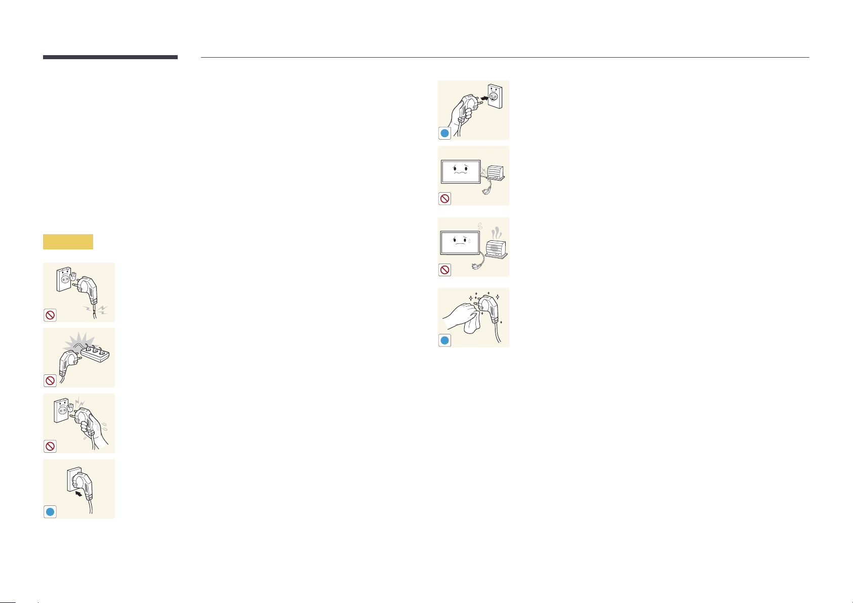
The following images are for reference only. Real-life situations may differ from what is shown in the
images.
Warning
Do not use a damaged power cord or plug, or a loose power socket.
•
An electric shock or fire may result.
Do not use multiple products with a single power socket.
•
Overheated power sockets may cause a fire.
Connect the power plug to a grounded power socket (type 1 insulated
devices only).
•
An electric shock or injury may result.
!
Do not bend or pull the power cord with force. Be careful not to leave the
power cord under a heavy object.
•
Damage to the cord may result in a fire or electric shock.
Do not place the power cord or product near heat sources.
•
A fire or electric shock may result.
Clean any dust around the pins of the power plug or the power socket with
a dry cloth.
•
A fire may result.
!
Do not touch the power plug with wet hands. Otherwise, an electric shock
may result.
Insert the power plug all the way in so it is not loose.
•
An unsecure connection may cause a fire.
!
9
Page 10

Caution
!
!
!
Do not disconnect the power cord while the product is being used.
•
The product may become damaged by an electric shock.
Only use the power cord provided with your product by Samsung. Do not
use the power cord with other products.
•
A fire or electric shock may result.
Keep the power socket where the power cord is connected unobstructed.
•
The power cord must be disconnected to cut off power to the product
when an issue occurs.
•
Note that the product is not completely powered down by using only
the power button on the remote.
Hold the plug when disconnecting the power cord from the power socket.
•
An electric shock or fire may result.
Installation
Warning
!
DO NOT PLACE CANDLES, INSECT REPELLANTS OR CIGARETTES ON TOP OF
THE PRODUCT. DO NOT INSTALL THE PRODUCT NEAR HEAT SOURCES.
•
A fire may result.
Have a technician install the wall-mount hanger.
•
Installation by an unqualified person can result in an injury.
•
Only use approved cabinets.
Do not install the product in poorly ventilated spaces such as a bookcase or
closet.
•
An increased internal temperature may cause a fire.
Install the product at least 10 cm away from the wall to allow ventilation.
•
An increased internal temperature may cause a fire.
!
Keep the plastic packaging out of the reach of children.
•
Children may suffocate.
!
10
Page 11

Do not install the product on an unstable or vibrating surface (insecure shelf,
sloped surface, etc.)
•
The product may fall and become damaged and/or cause an injury.
•
Using the product in an area with excess vibration may damage the
product or cause a fire.
Caution
Do not drop the product while moving.
•
Product failure or personal injury may result.
Do not install the product in a vehicle or a place exposed to dust, moisture
!
(water drips, etc.), oil, or smoke.
•
A fire or electric shock may result.
!
Do not set down the product on its front.
•
The screen may become damaged.
Do not expose the product to direct sunlight, heat, or a hot object such as a
stove.
•
The product lifespan may be reduced or a fire may result.
Do not install the product within the reach of young children.
•
The product may fall and injure children.
•
As the front is heavy, install the product on a flat and stable surface.
Edible oil, such as soybean oil, can damage or deform the product. Do not
!
When installing the product on a cabinet or shelf, make sure that the
bottom edge of the front of the product is not protruding.
•
The product may fall and become damaged and/or cause an injury.
•
Install the product only on cabinets or shelves of the right size.
Set down the product gently.
•
Product failure or personal injury may result.
install the product in a kitchen or near a kitchen counter.
Installing the product in an unusual place (a place exposed to a lot of fine
dust, chemical substances, extreme temperatures or a significant presence
of moisture, or a place where the product will operate continuously for an
SAMSUNG
!
extended period of time) may seriously affect its performance.
•
Be sure to consult Samsung Customer Service Centre if you want to
install the product at such a place.
11
Page 12

Operation
Warning
Do not leave heavy objects or items that children like (toys, sweets, etc.) on
top of the product.
•
The product or heavy objects may fall as children try to reach for the
toys or sweets resulting in a serious injury.
There is a high voltage inside the product. Never disassemble, repair or
modify the product yourself.
•
A fire or electric shock may result.
•
Contact Samsung Customer Service Centre for repairs.
!
Before moving the product, turn off the power switch and disconnect the
power cable and all other connected cables.
•
Damage to the cord may result in a fire or electric shock.
!
If the product generates abnormal sounds, a burning smell or smoke,
disconnect the power cord immediately and contact Samsung Customer
Service Centre.
•
An electric shock or fire may result.
!
Do not let children hang from the product or climb on top of it.
•
Children may become injured or seriously harmed.
If the product is dropped or the outer case is damaged, turn off the power
switch and disconnect the power cord. Then contact Samsung Customer
Service Centre.
•
Continued use can result in a fire or electric shock.
!
!
GAS
During a lightning or thunderstorm, power off the product and remove the
power cable.
•
A fire or electric shock may result.
Do not drop objects on the product or apply impact.
•
A fire or electric shock may result.
Do not move the product by pulling the power cord or any cable.
•
Product failure, an electric shock or fire may result from a damaged
cable.
If a gas leakage is found, do not touch the product or power plug. Also,
ventilate the area immediately.
•
Sparks can cause an explosion or fire.
Do not lift or move the product by pulling the power cord or any cable.
•
Product failure, an electric shock or fire may result from a damaged
cable.
12
Page 13

Do not use or keep combustible spray or an inflammable substance near
the product.
•
An explosion or fire may result.
!
Ensure the vents are not blocked by tablecloths or curtains.
•
An increased internal temperature may cause a fire.
100
Do not insert metallic objects (chopsticks, coins, hairpins, etc) or objects
that burn easily (paper, matches, etc) into the product (via the vent or input/
output ports, etc).
•
Be sure to power off the product and disconnect the power cord
when water or other foreign substances have entered the product.
Then contact Samsung Customer Service Centre.
•
Product failure, an electric shock or fire may result.
Caution
!
-_-
!
!
Leaving the screen fixed on a stationary image for an extended period of
time may cause afterimage burn-in or defective pixels.
•
Activate power-saving mode or a moving-picture screen saver if you
will not be using the product for an extended period of time.
Disconnect the power cord from the power socket if you do not plan on
using the product for an extended period of time (vacation, etc).
•
Dust accumulation combined with heat can cause a fire, electric shock
or electric leakage.
Use the product at the recommended resolution and frequency.
•
Your eyesight may deteriorate.
Do not place objects containing liquid (vases, pots, bottles, etc) or metallic
objects on top of the product.
•
Be sure to power off the product and disconnect the power cord
when water or other foreign substances have entered the product.
Then contact Samsung Customer Service Centre.
•
Product failure, an electric shock or fire may result.
Do not hold the product upside-down or move it by holding the stand.
•
The product may fall and become damaged or cause an injury.
Looking at the screen too close for an extended period of time can
deteriorate your eyesight.
!
Do not use humidifiers or stoves around the product.
•
A fire or electric shock may result.
13
Page 14

Rest your eyes for more than 5 minutes for every 1 hour of product use.
•
Eye fatigue will be relieved.
!
Be careful that children do not place the battery in their mouths when
removed from the remote control. Place the battery in a location that
children or infants cannot reach.
•
If children have had the battery in their mouths, consult your doctor
immediately.
Do not touch the screen when the product has been turned on for an
extended period of time as it will become hot.
Store small accessories out of the reach of children.
!
Exercise caution when adjusting the product angle or stand height.
•
Your hand or finger may get stuck and injured.
•
Tilting the product at an excessive angle may cause the product to fall
!
and an injury may result.
Do not place heavy objects on the product.
•
Product failure or personal injury may result.
When using headphones or earphones, do not turn the volume too high.
•
Having the sound too loud may damage your hearing.
!
!
When replacing the battery, insert it with the right polarity (+, -).
•
Otherwise, the battery may become damaged or it may cause fire,
personal injury or damage due to leakage of the internal liquid.
Use only the specified standardized batteries, and do not use a new battery
and a used battery at the same time.
•
Otherwise, the batteries may be damaged or cause fire, personal injury
or damage due to a leakage of the internal liquid.
The batteries (and rechargeable batteries) are not ordinary refuse and must
be returned for recycling purposes. The customer is responsible for returning
the used or rechargeable batteries for recycling.
•
The customer can return used or rechargeable batteries to a nearby
public recycling centre or to a store selling the same type of the
battery or rechargeable battery.
14
Page 15
Precautions when handling the panel
―
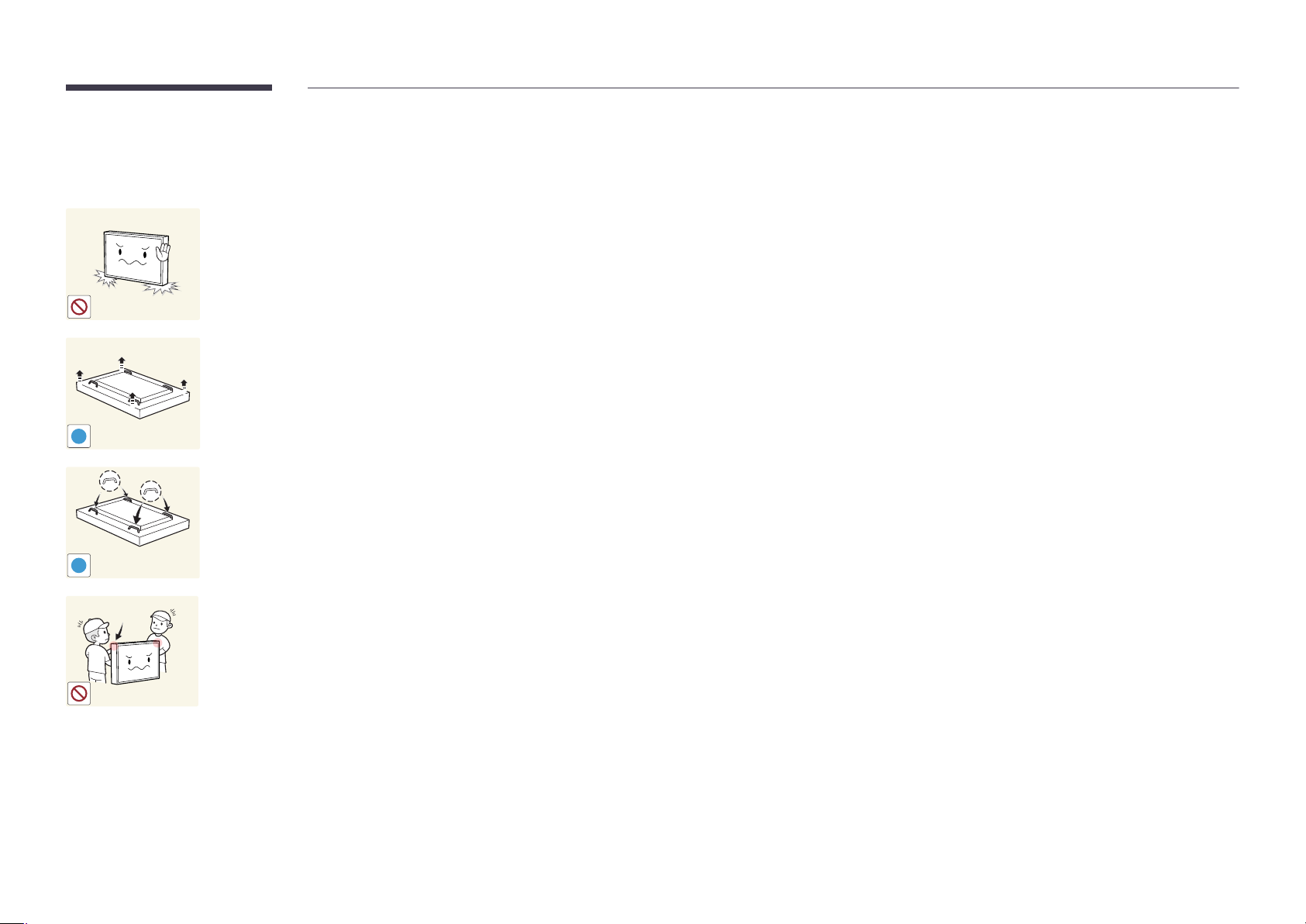
DM75E-BR, DM82E-BR models are only supported.
Do not stand the product as shown in the image. The panel is fragile and
can get damaged.
Lay the product down to handle it as shown in the image. (the packaging
can be used).
!
Ensure you use the handles on the back when moving the product.
!
15 mm
Do not hold or grasp any area of the product within 15 mm from the front.
15
Page 16

Chapter 02
Preparations
-
Contact the vendor where you
purchased the product if any
components are missing.
-
The appearance of the components may
differ from the images shown.
-
A stand is not provided with the product.
To install a stand, you can purchase one
separately.
-
The RS232C adapter can be used to
connect to another monitor using the
D-SUB (9-pin) type RS232C cable.
Checking the Components
Components
―
Components may differ in different locations.
Quick Setup Guide
Warranty card
(Not available in some locations)
Regulatory guide Power cord
-
-
Batteries
(Not available in some locations)
+
+
Remote Control RS232C(IN) adapter Tray Screw (M4L10, 11 EA) OCM cable
16
Page 17

External sensor KIT USB cable Cable grip Wire holders Touch Pen (1 EA)
Holder-Ring (4 EA)
Double-sided tape (6 EA)
(DM65E-BR, DM75E-BR models
are only supported.)
17
Page 18

Parts
Control Panel
―
Models DM65E-BR and DM75E-BR are only supported.
Speaker
―
The colour and shape of parts may differ from what is shown. Specifications are subject to change without notice to
improve quality.
Panel Key
Buttons Description
Power on the product.
If you press the button when the product is turned on, the control menu will be
displayed.
―
To exit the OSD menu, press and hold the panel key for at least one second.
Move to the upper or lower menu. You can also adjust the value of an option.
Move to the left or right menu.
―
You can adjust the volume by moving the panel key left or right when the control
menu is not displayed.
Panel Key
18
Page 19

Parts
Control Panel
―
Model DM82E-BR is only supported.
Speaker
―
The colour and shape of parts may differ from what is shown. Specifications are subject to change without notice to
improve quality.
Panel Key
Buttons Description
Power on the product.
If you press the button when the product is turned on, the control menu will be
displayed.
―
To exit the OSD menu, press and hold the panel key for at least one second.
Move to the upper or lower menu. You can also adjust the value of an option.
Move to the left or right menu.
―
You can adjust the volume by moving the panel key left or right when the control
menu is not displayed.
Panel Key
19
Page 20

―
If you press the button on the panel key when the product is turned on, the
control menu will be displayed.
Control menu
Buttons Description
Select the connected input source.
Source
Menu
Move the panel key right to select Source
input sources is displayed, move the panel key left or right to select the desired input
source. Next, press the panel key.
Display the OSD menu.
Move the panel key left to select Menu
screen will appear. Move the panel key right to select the desired menu. You can
select a sub-menu item by moving the panel key up, down, left, or right. To change
settings, select the desired menu and press the panel key.
in the control menu. When the list of
in the control menu. The OSD control
Return
Home
Power o
Return
Enter Go to Home mode.
Move the panel key up to select Home
Power off the product.
Move the panel key down to select
the panel key.
Exit the control menu.
Power o
in the control menu.
in the control menu. Next, press
20
Page 21

External sensor KIT
―
The external sensor is integrated with the remote control sensor, light sensor and power indicator.
If mounting the display onto a wall, you can move the External sensor KIT to the side of the display.
―
The colour and shape of parts may differ from what is shown. Specifications are subject to change without notice to
improve quality.
Parts Description
IR /
AMBIENT
SENSOR IN
Light sensor
Remote Control Sensor
Power indicator
Use the remote control within 7 m to 10 m from the sensor on the product at an angle of 30
―
Store used batteries out of reach of children and recycle.
―
Do not use a new and used battery together. Replace both batteries at the same time.
―
Remove batteries when the remote control is not to be used for an extended period of time.
―
If you disconnect the power cord from the product while it is in standby mode, the product remains in standby mode until
it runs out of power. The power indicator turns on or blinks during this time. If you reconnect the power cord, the input
source activates and the product resumes normal operation.
Automatically detects the intensity of ambient light around a selected display and
adjusts the screen brightness.
Aim the remote control towards this spot on the LCD Display.
―
Using other display devices in the same space as the remote control of this
product can cause the other display devices to be inadvertently controlled.
The power indicator will turn off when the product is turned on. It will blink in
power-saving mode.
from the left and right.
21
Page 22

Reverse Side
Port Description
―
The colour and shape of parts may differ from what is shown. Specifications are
subject to change without notice to improve quality.
―
Models DM65E-BR and DM75E-BR are only supported.
IR /
AMBIENT
SENSOR IN
RGB / DVI /
HDMI / AV /
COMPONENT
/ AUDIO IN
USB
USB
(5V 1A) /
TOUCH IN
DVI IN /
MAGICINFO IN
RS232C IN
RS232C OUT
IR / AMBIENT SENSOR IN
RGB / DVI / HDMI / AV / COMPONENT /
AUDIO IN
AUDIO OUT
USB
USB (5V 1A) / TOUCH IN
DVI IN / MAGICINFO IN
DP IN
HDMI IN 1 / HDMI IN 2
TRAY IN
RGB IN
Connects to MDC using an RS232C adapter.
Supplies power to the external sensor board or receives the light sensor signal.
Receives sound from a PC via an audio cable.
Connects to the audio of a source device.
Connect to a USB memory device.
USB (5V 1A): Connects to a USB device. Make sure the Touch is not in use.
TOUCH IN: This must be connected to the cable if the Touch is in use.
DVI IN: Connects to a source device using a DVI cable or HDMI-DVI cable.
MAGICINFO IN: Use the (dedicated) DP-DVI cable when connecting a network
box (sold separately).
Connects to a PC using a DP cable.
Connects to a source device using an HDMI cable.
Connects to the Tray, found on the front of the product, using the OCM cable.
Connects to a source device using a D-SUB cable.
DP IN
HDMI IN 1
HDMI IN 2
TRAY IN RJ45RGB IN
TOUCH
OUT
COMPONENT IN
TOUCH OUT
AV IN / COMPONENT IN
RJ45
Connects the Touch to a PC.
Connects to a source device using the AV/Component adapter.
Connects to MDC using a LAN cable.
22
Page 23

Reverse Side
―
The colour and shape of parts may differ from what is shown. Specifications are
subject to change without notice to improve quality.
―
Model DM82E-BR is only supported.
Port Description
RS232C IN
RS232C OUT
IR / AMBIENT SENSOR IN
Connects to MDC using an RS232C adapter.
Supplies power to the external sensor board or receives the light sensor signal.
RS232C IN
RS232C
OUT
IR /
AMBIENT
SENSOR IN
RGB / DVI /
HDMI / AV /
COMPONENT
AUDIO IN
AUDIO
OUT
SD CARD
USB
(5V 1A)
USB
(5V 1A) /
TOUCH IN
DVI /
MAGICINFO IN
DP IN
HDMI IN 1
HDMI IN 2
TRAY IN RJ45RGB IN
TOUCH OUT
COMPONENT IN
OUT
RGB / DVI / HDMI / AV /
Receives sound from a PC via an audio cable.
COMPONENT AUDIO IN
AUDIO OUT
SD CARD
USB (5V 1A)
Connects to the audio of a source device.
Connect to an SD memory card.
Connect to a USB memory device.
―
The USB ports on the product accept a maximum constant current of 1A. If the
maximum value is exceeded, USB ports may not work.
USB (5V 1A) / TOUCH IN
USB (5V 1A): Connects to a USB device. Make sure the Touch is not in use.
TOUCH IN: This must be connected to the cable if the Touch is in use.
DVI / MAGICINFO IN
DVI: Connects to a source device using a DVI cable or HDMI-DVI cable.
MAGICINFO IN: Use the (dedicated) DP-DVI cable when connecting a network box (sold
separately).
DP IN
HDMI IN1 / HDMI IN 2
TRAY IN
RGB IN
TOUCH OUT
IR
AV IN / COMPONENT IN
IR OUT
Connects to a PC using a DP cable.
Connects to a source device using an HDMI cable.
Connects to the Tray, found on the front of the product, using the OCM cable.
Connects to a source device using a D-SUB cable.
Connects the Touch to a PC.
Connects to a source device using the AV/Component adapter.
Receives the remote control signal via the external sensor board and outputs the signal via
LOOP OUT.
RJ45
Connects to MDC using a LAN cable.
23
Page 24

Tray
―
The colour and shape of parts may differ from what is shown. Specifications are
subject to change without notice to improve quality.
Buttons & Port Description
TOUCH ON/OFF
Turns the Touch on or off.
QUICK MENU
POWER ON/OFF
HDMI IN Connects to a source device using an HDMI cable.
TOUCH OUT Connects the Touch to a PC.
TRAY OUT Connect the OCM cable to the tray and the TRAY IN port on the product.
CONTROL IN Connect the IR Touch Control cable to the tray.
View menus of the display device.
Turns the product on or off.
Connect to a USB memory device.
24
Page 25

Installing the Tray
―
The colour and shape of parts may differ from what is shown. Specifications are subject to change without notice to improve quality.
―
When attaching the Tray, use the screws that came with the package.
Do not fasten the screws with excessive force. The product may get damaged.
―
IR touch input may malfunction if the device is exposed to direct or reflected sun light or other bright light.
When installing the monitor, avoid locations with nearby metal halide, incandescent or halogen lamps, and locations near sunlit windows.
25
Page 26

Using the touch function
―
The colour and shape of parts may differ from what is shown. Specifications are subject to change without notice to improve quality.
Connect the IR Touch USB cable to the USB (5V 1A) / TOUCH IN port on the product.
1
Connect the IR Touch Control cable to the tray.
2
Connect the OCM cable to the tray and the TRAY IN port on the product.
3
To use the touch function with a Network box (sold separately) or computer connected to the product, use the PC Touch cable to connect the TOUCH OUT port on the product to the USB port on the Network
4
box or computer.
26
Page 27

Plug In Module (Sold separately)
Anti-theft Lock
―
The colour and shape of parts may differ from what is shown. Specifications are subject to change
without notice to improve quality.
PIM Slot
To use Plug In Module, make sure you connect a Samsung PIM (sold separately).
To connect a device made by another manufacturer, ensure the device is compatible with Open
Pluggable Specification (OPS) standards.
―
For details on how to connect a device, refer to the user manual provided with the PIM upon purchase.
―
To obtain optimum audio quality, configure the HDMI audio settings using the Windows Control Panel
on the OPS device. For products made by other manufacturers, this only applies to HDMI compatible
devices.
―
To enable sound output from the product with an OPS device that does not support HDMI, configure
the analogue audio settings using the Windows Control Panel, go to Plug In Module > Edit Name
and set the input source to PC, DVI PC or DVI.
―
An anti-theft lock allows you to use the product securely even in public places.
―
The locking device shape and locking method depend on the manufacturer. Refer to the user guide
provided with your anti-theft locking device for details.
―
The following images are for reference only. Real-life situations may differ from what is shown in the
images.
To lock an anti-theft locking device:
Fix the cable of your anti-theft locking device to a heavy object such as a desk.
1
Put one end of the cable through the loop on the other end.
2
Insert the locking device into the anti-theft lock slot at the back of the product.
3
Lock the locking device.
4
-
An anti-theft locking device can be purchased separately.
-
Refer to the user guide provided with your anti-theft locking device for details.
-
Anti-theft locking devices can be purchased at electronics retailers or online.
27
Page 28

Spacer logo
Do not pull on the spacer logo using force. The logo may tear or break off.
―
The colour and shape of parts may differ from what is shown. Specifications are subject to change without notice to
improve quality.
28
Page 29

CH
DEL-/--
CH LIST
Remote Control
―
Using other display devices in the same space as the remote control of this product can cause the other display devices to be inadvertently controlled.
―
A button without a description in the image below is not supported on the product.
Power on the product.
Adjust the volume.
Change the input source.
Display or hide the onscreen display menu, or
return to the previous menu.
.QZ
1
GHI
4
PRS
7
VOL
MENU
ABC
2
JKL
5
TUV
8
SYMBOL
0
MUTE
SOURCE
HOME
POWER
OFF
DEF
3
MNO
6
WXY
9
MagicInfo
Player I
Power off the product.
Number buttons
Enter the password in the OSD menu.
Mute the sound.
Unmuting the sound: Press MUTE again or press
the volume control(+ VOL -) button.
Use this hotkey to directly access MagicInfo. This
hotkey is available when a network box or PIM
(Plug In Module) is connected.
Go to Home Launch Button.
-
Remote control button functions may
differ for different products.
29
Page 30

Quickly select frequently used functions.
TOOLS INFO
Display information about the current input
source.
Move to the upper, lower, left or right menu, or
adjust an option's setting.
Confirm a menu selection.
Return to the previous menu.
It sets safe lock function.
If multiple products are connected through the
Video Wall feature, press the SET button and
enter a product ID using the number buttons.
Control the product using the remote control.
Cancel a value that has been set using the
SET button and control all connected products
using the remote control.
To place batteries in the remote control
PC
A
SET
IR control
DVI
B
UNSET
HDMI
C
LOCK
EXITRETURN
DP
D
Exit the current menu.
Manually select a connected input source from
PC, DVI, HDMI or DisplayPort.
-
Remote control button functions may
differ for different products.
Used in Anynet+ mode and multimedia mode.
30
Page 31
Connection Using an IR Stereo Cable (sold
separately)
―
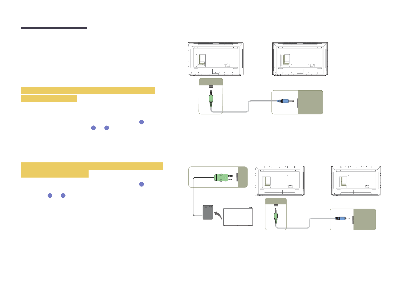
The DM65E-BR and DM75E-BR models do not support the IR OUT port.
Make sure to connect the External ambient sensor while the product is powered
off. Then, power on the product.
Controlling more than one display product using
your remote control
•
Connect the IR OUT port on the product to the IR / AMBIENT SENSOR IN
port on the other display product using the dedicated stereo cable.
•
A command sent from the remote control pointed at product
1
received by both display products
―
The appearance may differ depending on the product.
and 2.
1
will be
1 2
IR OUT IR / AMBIENT
SENSOR IN
Controlling more than one display product using an
External ambient sensor
•
A command sent from the remote control pointed at product
the External ambient sensor is connected) will be received by both display
products
―
The appearance may differ depending on the product.
1
and 2.
1
(to which
IR / AMBIENT
SENSOR IN
1 2
IR OUT IR / AMBIENT
SENSOR IN
31
Page 32
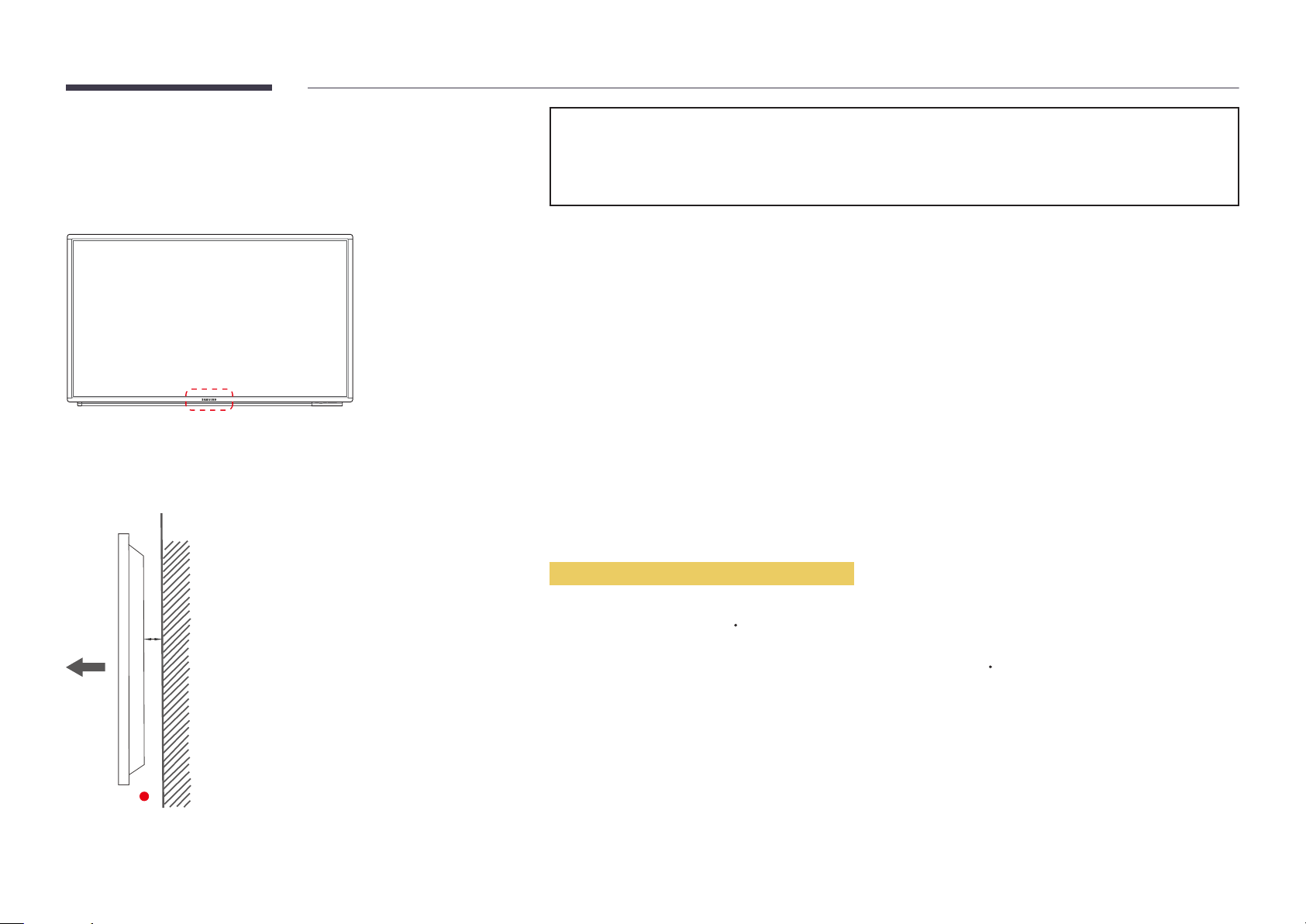
Before Installing the Product
(Installation Guide)
To prevent injury, this apparatus must be securely attached to the floor/wall in accordance with the installation instructions.
•
Ensure that an authorized installation company installs the wall mount.
•
Otherwise, it may fall and cause personal injury.
•
Make sure to install the specified wall mount.
―
Contact Samsung Customer Service Centre for further details.
Ventilation
A
B
Figure 1.1 Side view
Installation on a Perpendicular Wall
A Minimum 40 mm
B Ambient temperature: Under 35
•
When installing the product on a perpendicular wall, allow at least 40 mm of space between the product and wall surface
for ventilation and ensure that the ambient A temperature is kept below 35
C
C.
32
Page 33
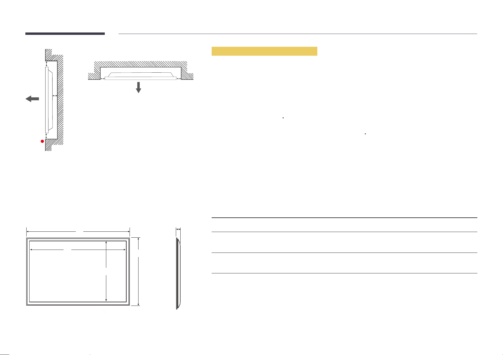
Figure 1.3 Side view
B
Installation on an Indented Wall
―
Contact Samsung Customer Service Centre for further details.
A
C
E
Figure 1.2 Side view
Dimensions
1
2
D D
5
4
3
Plane view
A Minimum 40 mm
B Minimum 70 mm
C Minimum 50 mm
D Minimum 50 mm
E Ambient temperature: Under 35
―
When installing the product on an indented wall, allow at least the space specified above between the product and wall for
ventilation and ensure that the ambient temperature is kept below 35
Model name
DM65E-BR 1535.3 (60.44) 1431.4 (56.35) 806.6 (31.76) 910.4 (35.84) 76.6 (3.02)
DM75E-BR 1756.1 (69.14) 1652.2 (65.05) 930.2 (36.62) 1034.1 (40.71) 109.1 (4.30) (74.1 (2.92)
DM82E-BR 1911.8 (75.27) 1831.9 (72.12) 1041.9 (41.02) 1121.7 (44.16) 178.0 (7.01) (140 (5.51)
―
All drawings are not necessarily to scale. Some dimensions are subject to change without prior notice.
Refer to the dimensions prior to performing installation of your product. Not responsible for typographical or printed errors.
1
C
C.
Unit: mm (inches)
2 3 4 5
Without Handle)
Without Handle)
33
Page 34
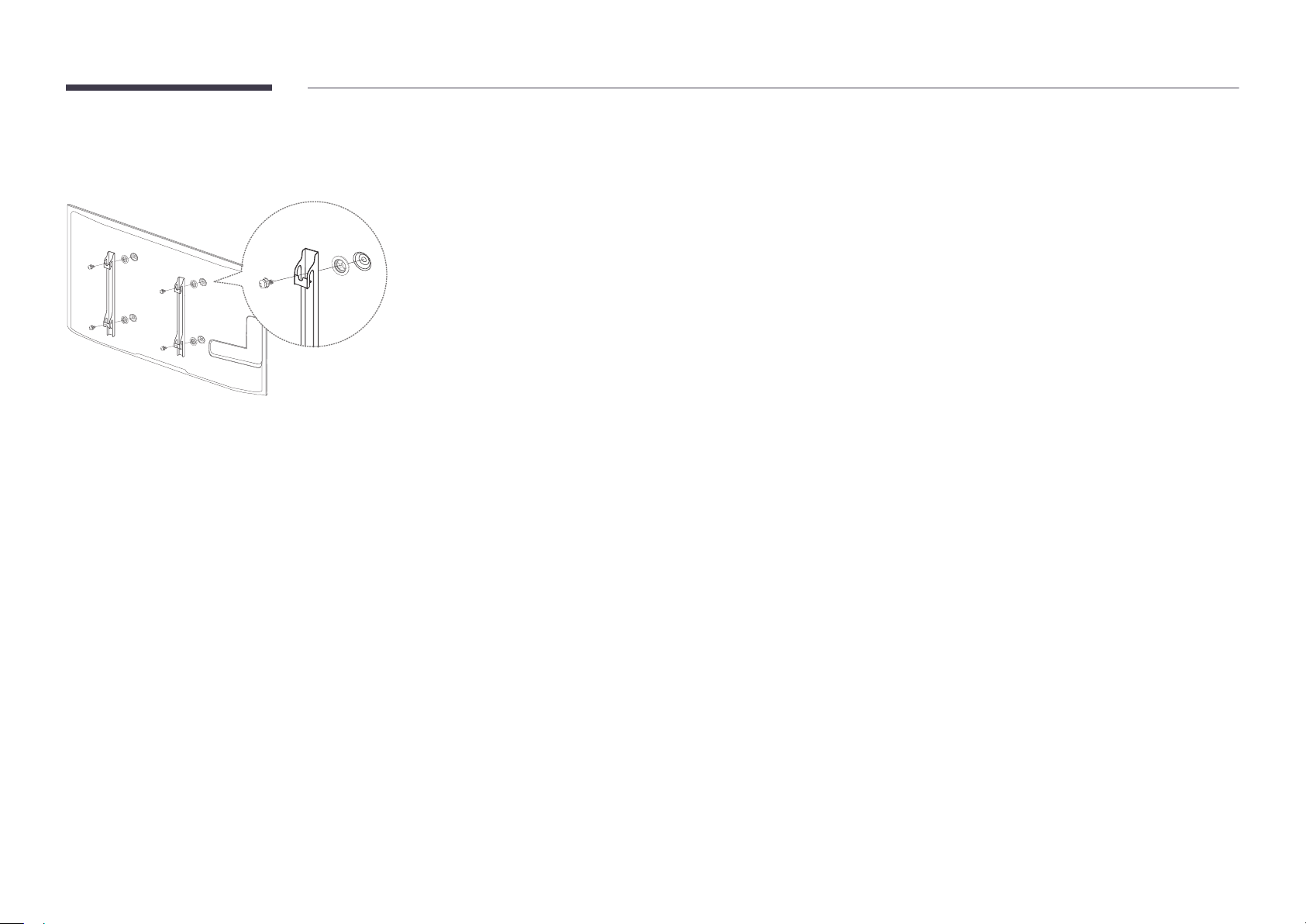
Installing the Wall Mount
Preparing before installing Wall-Mount
To install a wall-mount from another manufacturer, use the Holder-Ring(1).
―
DM65E-BR, DM75E-BR models are only supported.
Installing the Wall Mount
1
The wall mount kit (sold separately) allows you to mount the product on the wall.
For detailed information on installing the wall mount, see the instructions provided with the wall mount.
We recommend you contact a technician for assistance when installing the wall mount bracket.
Samsung Electronics is not responsible for any damage to the product or injury to yourself or others if you elect to install the
wall mount on your own.
34
Page 35
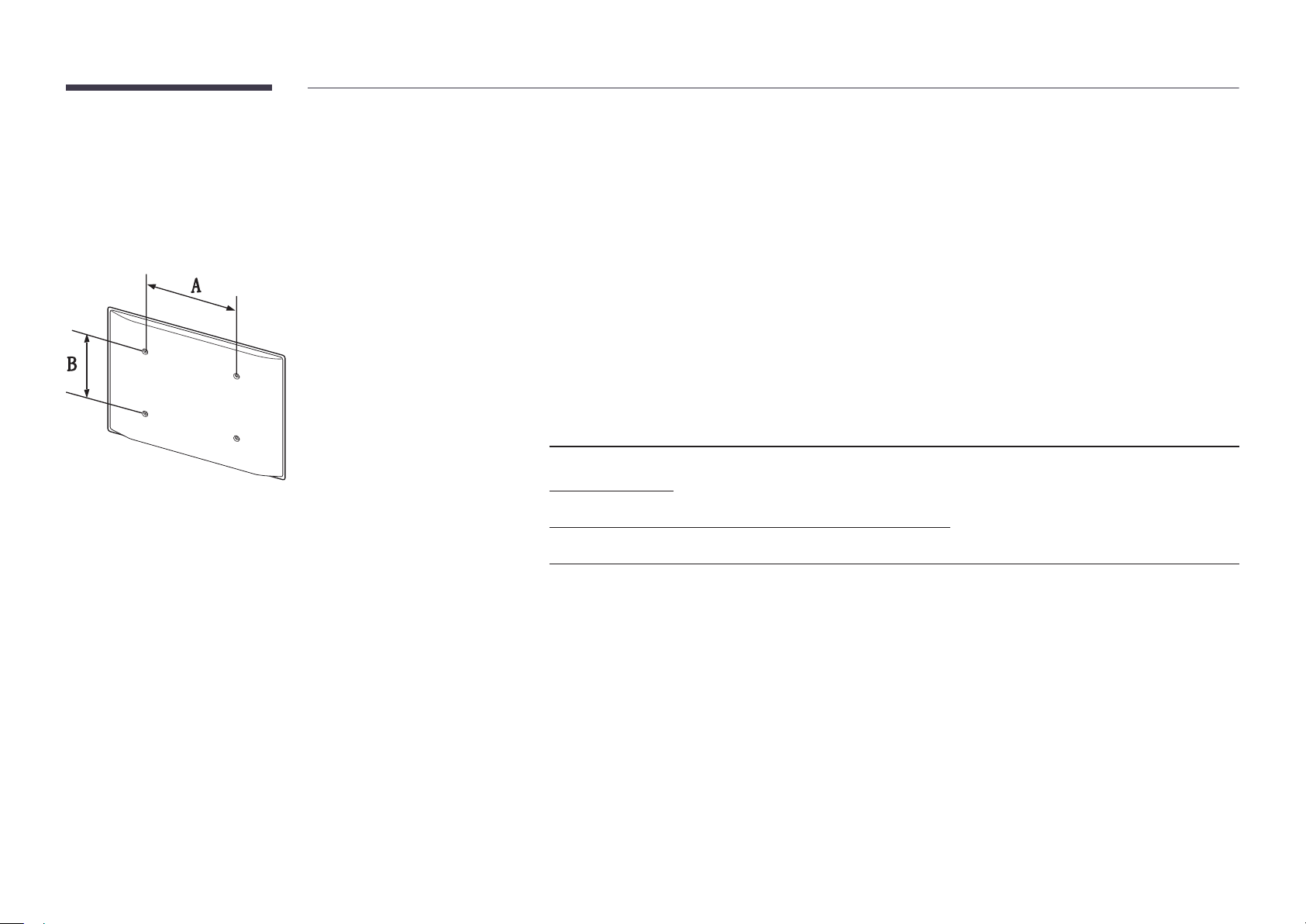
Wall Mount Kit Specications (VESA)
―
Install your wall mount on a solid wall perpendicular to the floor. Before
attaching the wall mount to surfaces other than plaster board, please contact
your nearest dealer for additional information.
If you install the product on a slanted wall, it may fall and result in severe
personal injury.
•
Samsung wall mount kits contain a detailed installation manual and all parts necessary for assembly are provided.
•
Do not use screws that are longer than the standard length or do not comply with the VESA standard screw
specifications. Screws that are too long may cause damage to the inside of the product.
•
For wall mounts that do not comply with the VESA standard screw specifications, the length of the screws may differ
depending on the wall mount specifications.
•
Do not fasten the screws too firmly. This may damage the product or cause the product to fall, leading to personal injury.
Samsung is not liable for these kinds of accidents.
•
Samsung is not liable for product damage or personal injury when a non-VESA or non-specified wall mount is used or the
consumer fails to follow the product installation instructions.
•
Always have two people mount the product on a wall.
•
Standard dimensions for wall mount kits are shown in the table below.
Unit: mm (inches)
Model name VESA screw hole specs (A * B) in
Standard Screw Quantity
millimeters
DM65E-BR
400 × 400 (15.7 × 15.7)
DM75E-BR
DM82E-BR 600 × 400 (23.6 × 15.7)
―
Do not install your Wall Mount Kit while your product is turned on. It may result in personal injury due to electric shock.
M8 4
35
Page 36
Remote Control (RS232C)
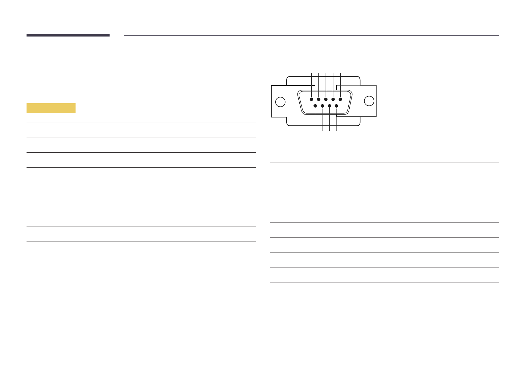
Cable Connection
RS232C Cable
•
Pin assignment
1 2 3 4 5
Interface
Pin
Bit rate
Data bits
Parity
Stop bit
Flow control
Maximum length
RS232C (9 pins)
TxD (No.2), RxD (No.3), GND (No.5)
9600 bps
8 bit
None
1 bit
None
15 m (only shielded type)
6 7 8 9
Pin Signal
1
2
3
4
5
6
7
8
9
Detect data carrier
Received data
Transmitted data
Prepare data terminal
Signal ground
Prepare data set
Send request
Clear to send
Ring indicator
36
Page 37
•
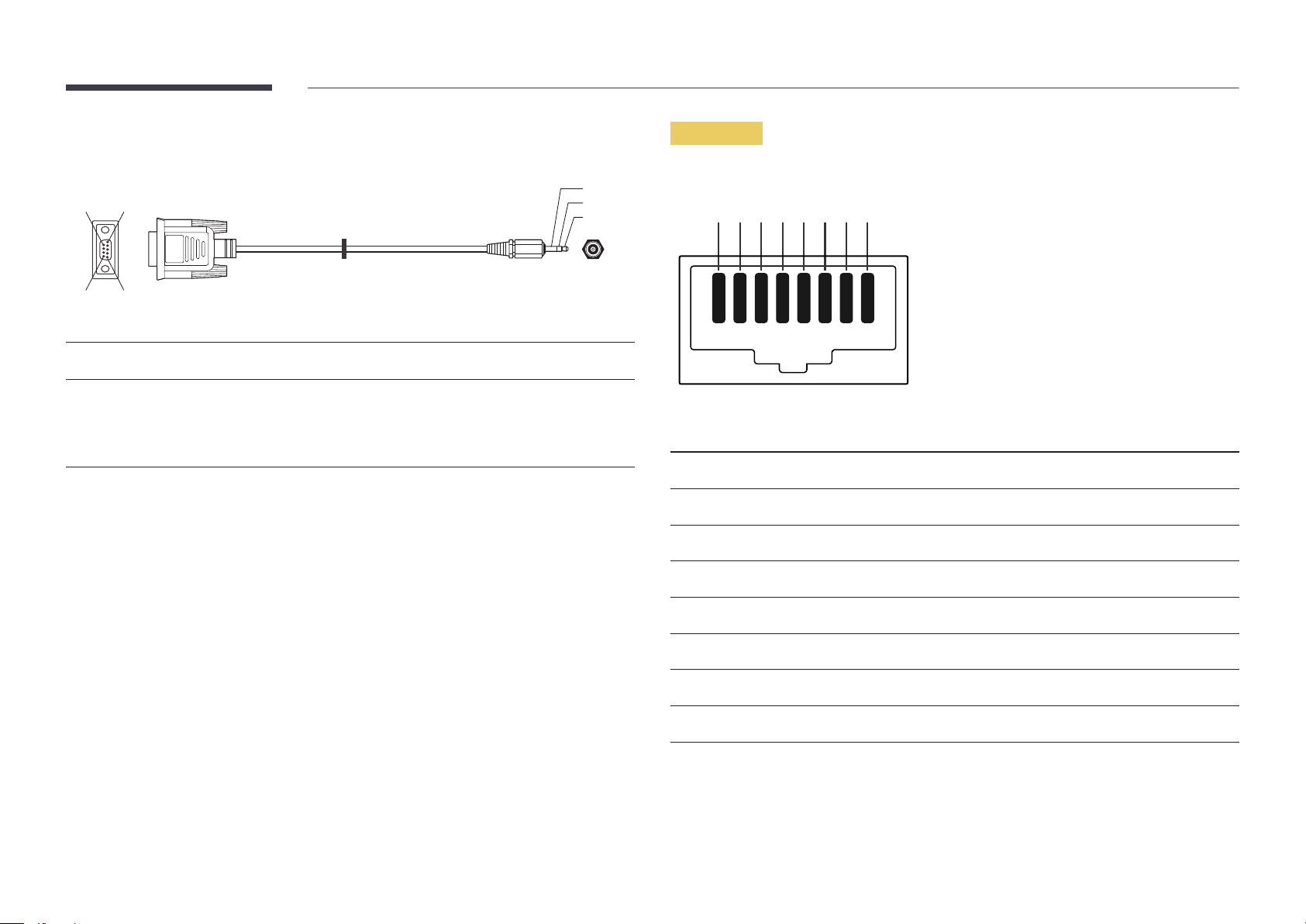
RS232C cable
Connector: 9-Pin D-Sub to Stereo Cable
59
1
6
-P1-
-P1- -P1- -P2- -P2-
3
2
1
-P2-
LAN Cable
•
Pin assignment
1 2 3 4 5 6 7 8
Female Rx
Tx
Gnd
2
3
5
-------->
<--------
----------
3
2
5
Tx
Rx
Gnd
STEREO
PLUG
(3.5ø)
Pin No Standard Colour Signal
1 White and orange TX+
2 Orange TX-
3 White and green RX+
4 Blue NC
5 White and blue NC
6 Green RX-
7 White and brown NC
8 Brown NC
37
Page 38

•
Connector : RJ45
Direct LAN cable (PC to HUB)
Cross LAN cable (PC to PC)
HUB
P1P2
RJ45 RJ45 MDC
Signal
TX+
TX-
RX+
RX-
P1
P1 P2 Signal
1 <--------> 1 TX+
2 <--------> 2 TX-
3 <--------> 3 RX+
6 <--------> 6 RX-
P2
Signal
TX+
TX-
RX+
RX-
RJ45
P1 P2
P1 P2 Signal
1 <--------> 3 RX+
2 <--------> 6 RX-
3 <--------> 1 TX+
6 <--------> 2 TX-
38
Page 39
Connection
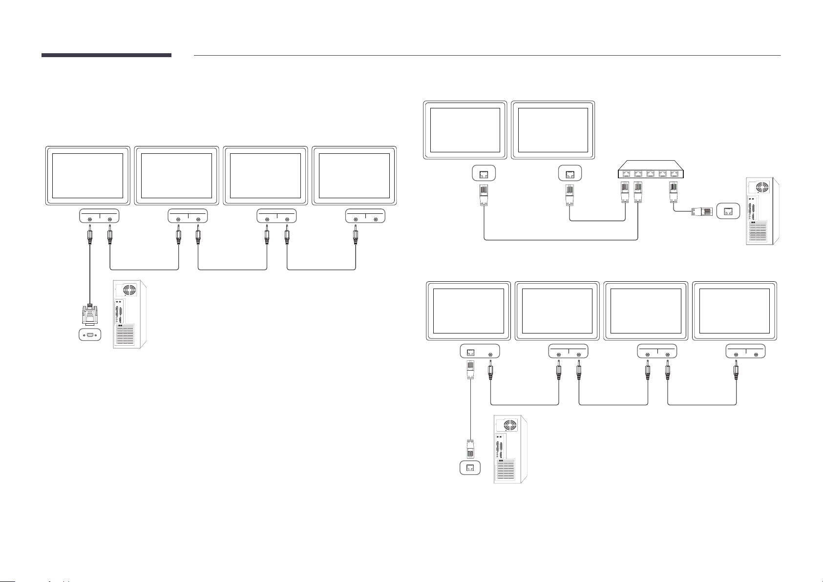
―
Ensure you connect each of the adapters to the correct RS232C IN or OUT port on the product.
•
Connection 1
•
Connection 2
RJ45 RJ45
RS232C
IN OUT
RS232C
IN OUT
RS232C
IN OUT
RS232C
IN OUT
•
Connection 3
RS232C
RJ45 RS232C
OUT
IN OUT
RS232C
IN OUT
RS232C
IN OUT
39
Page 40
Control Codes
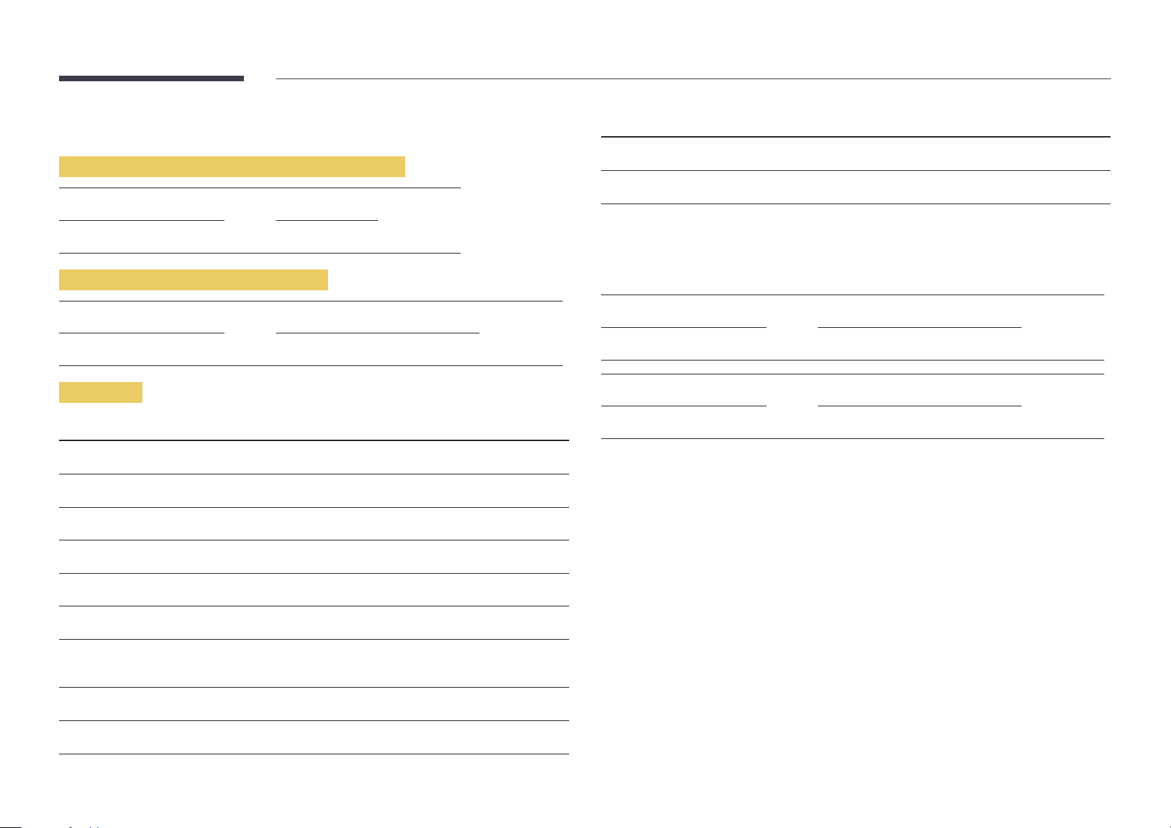
No. Command type Command Value range
Viewing control state (Get control command)
Header Command ID Data length Checksum
0xAA Command type 0
Controlling (Set control command)
Header Command ID Data length Data Checksum
0xAA Command type 1 Value
Command
No. Command type Command Value range
1
2
3
4
Power control 0x11 0~1
Volume control 0x12 0~100
Input source control 0x14 -
Screen mode control 0x18 -
10
11
•
All communications take place in hexadecimals. The checksum is calculated by adding up all
values except the header. If a checksum adds up to be more than 2 digits as shown below
(11+FF+01+01=112), the first digit is removed.
E.g. Power On & ID=0
Header Command ID Data length Data 1 Checksum
0xAA 0x11 1 "Power"
Header Command ID Data length Data 1 12
0xAA 0x11 1 1
•
To control all devices connected by a serial cable simultaneously irrespective of IDs, set the ID as
"0xFE" and transmit commands. Commands will be executed by each device but ACK will not
respond.
Video Wall On 0x84 0~1
Video Wall User Control 0x89 -
5
6
7
8
9
Screen size control 0x19 0~255
PIP on/off control 0x3C 0~1
Auto adjustment control (PC and
BNC only)
Video wall mode control 0x5C 0~1
Safety Lock 0x5D 0~1
0x3D 0
40
Page 41
Power control
Volume control
•
Function
A product can be powered on and off using a PC.
•
Viewing power state (Get Power ON / OFF Status)
Header Command ID Data length Checksum
0xAA 0x11 0
•
Setting power ON/Off (Set Power ON / OFF)
Header Command ID Data length Data Checksum
0xAA 0x11 1 "Power"
"Power": Power code to be set on a product.
1: Power ON
0: Power OFF
•
Ack
Header Command ID Data length Ack/Nak r-CMD Val1 Checksum
0xAA 0xFF 3 'A' 0x11 "Power"
"Power": Power code to be set on a product.
•
Nak
Header Command ID Data length Ack/Nak r-CMD Val1 Checksum
•
Function
The volume of a product can be adjusted using a PC.
•
Viewing volume state (Get Volume Status)
Header Command ID Data length Checksum
0xAA 0x12 0
•
Setting the volume (Set Volume)
Header Command ID Data length Data Checksum
0xAA 0x12 1 "Volume"
"Volume": Volume value code to be set on a product. (0-100)
•
Ack
Header Command ID Data length Ack/Nak r-CMD Val1 Checksum
0xAA 0xFF 3 'A' 0x12 "Volume"
"Volume": Volume value code to be set on a product. (0-100)
•
Nak
Header Command ID Data length Ack/Nak r-CMD Val1 Checksum
0xAA 0xFF 3 'N' 0x12 "ERR"
0xAA 0xFF 3 'N' 0x11 "ERR"
"ERR" : A code showing what error has occurred.
"ERR" : A code showing what error has occurred.
41
Page 42
Input source control
•
Function
The input source of a product can be changed using a PC.
•
Viewing input source state (Get Input Source Status)
Header Command ID Data length Checksum
0xAA 0x14 0
•
Setting the input source (Set Input Source)
Header Command ID Data length Data Checksum
0xAA 0x14 1 "Input Source"
"Input Source": An input source code to be set on a product.
0x24 HDMI2_PC
0x25 DisplayPort
―
DVI_video, HDMI1_PC and HDMI2_PC cannot be used with the Set command. They only respond to
"Get" commands.
―
This model does not support HDMI1, HDMI1_PC, HDMI2 and HDMI2_PC ports.
―
MagicInfo is only available with models that contain the MagicInfo function.
―
RF(TV), DTV are only available with models that include a TV.
•
Ack
Header Command ID Data length Ack/Nak r-CMD Val1 Checksum
0xAA 0xFF 3 'A' 0x14 "Input
Source"
0x14 PC
0x18 DVI
0x0C Input source
0x08 Component
0x20 MagicInfo
0x1F DVI_video
0x30 RF( TV )
0x40 DT V
0x21 HDMI1
0x22 HDMI1_PC
0x23 HDMI2
"Input Source": An input source code to be set on a product.
•
Nak
Header Command ID Data length Ack/Nak r-CMD Val1 Checksum
0xAA 0xFF 3 'N' 0x14 "ERR"
"ERR" : A code showing what error has occurred.
42
Page 43
Screen mode control
•
Function
The screen mode of a product can be changed using a PC.
Screen mode cannot be controlled when the Video Wall function is enabled.
―
This control can only be used on models that include a TV.
•
Viewing screen status (Get Screen Mode Status)
Header Command ID Data length Checksum
0xAA 0x18 0
•
Setting the picture size (Set Picture Size)
Header Command ID Data
length
0xAA 0x18 1 "Screen Mode"
"Screen Mode": A code that sets the product status
0x01 16 : 9
Data Checksum
•
Nak
Header Command ID Data length Ack/Nak r-CMD Val1 Checksum
0xAA 0xFF 3 'N' 0x18 "ERR"
"ERR": A code showing what error has occurred
Screen size control
•
Function
The screen size of a product can be changed using a PC.
•
Viewing the screen size (Get Screen Size Status)
Header Command ID Data length Checksum
0xAA 0x19 0
•
Ack
Header Command ID Data
length
Ack/Nak r-CMD Val1 Checksum
0x04 Zoom
0x31 Wide Zoom
0x0B 4 : 3
•
Ack
Header Command ID Data length Ack/Nak r-CMD Val1 Checksum
0xAA 0xFF 3 'A' 0x18 "Screen
Mode"
"Screen Mode": A code that sets the product status
0xAA 0xFF 3 'A' 0x19 "Screen Size"
"Screen Size": product screen size (range: 0 – 255, unit: inch)
•
Nak
Header Command ID Data
length
0xAA 0xFF 3 'N' 0x19 "ERR"
"ERR": A code showing what error has occurred
Ack/Nak r-CMD Val1 Checksum
43
Page 44
PIP On/Off control
Auto adjustment control (PC and BNC only)
•
Function
The PIP mode of a product can be turned on or off using a PC.
―
Only available on models that have the PIP function.
―
The mode cannot be controlled if Video Wall is set to On.
―
This function is not available in MagicInfo.
•
Viewing PIP on/off state (Get the PIP ON / OFF Status)
Header Command ID Data length Checksum
0xAA 0x3C 0
•
Setting PIP on/off (Set the PIP ON / OFF)
Header Command ID Data length Data Checksum
0xAA 0x3C 1 "PIP"
"PIP": A code used to turn the PIP mode of a product on or off
1: PIP ON
0: PIP OFF
•
Ack
Header Command ID Data
length
0xAA 0xFF 3 'A' 0x3C "PIP"
Ack/Nak r-CMD Val1 Checksum
•
Function
Automatically adjust the PC system screen using a PC.
•
Viewing auto adjustment state (Get Auto Adjustment Status)
None
•
Setting auto adjustment (Set Auto Adjustment)
Header Command ID Data length Data Checksum
0xAA 0x3D 1 "Auto
Adjustment"
"Auto Adjustment" : 0x00 (at all times)
•
Ack
Header Command ID Data
length
0xAA 0xFF 3 'A' 0x3D "Auto
•
Nak
Header Command ID Data
length
0xAA 0xFF 3 'A' 0x3D "ERR"
Ack/Nak r-CMD Val1 Checksum
Adjustment"
Ack/Nak r-CMD Val1 Checksum
"PIP": A code used to turn the PIP mode of a product on or off
•
Nak
Header Command ID Data
length
0xAA 0xFF 3 'A' 0x3C "PIP"
"ERR": A code showing what error has occurred
Ack/Nak r-CMD Val1 Checksum
"ERR": A code showing what error has occurred
44
Page 45
Video Wall Mode Control
Safety Lock
•
Function
Video Wall mode can be activated on a product using a PC.
This control is only available on a product whose Video Wall is enabled.
•
Viewing video wall mode (Get Video Wall Mode)
Header Command ID Data length Checksum
0xAA 0x5C 0
•
Setting the video wall (Set Video Wall Mode)
Header Command ID Data length Data Checksum
0xAA 0x5C 1 "Video Wall Mode"
"Video Wall Mode": A code used to activate Video Wall mode on a product
1: Full
0: Natural
•
Ack
Header Command ID Data
length
0xAA 0xFF 3 'A' 0x5C "Video Wall
"Video Wall Mode": A code used to activate Video Wall mode on a product
•
Nak
Header Command ID Data
length
0xAA 0xFF 3 'A' 0x5C "ERR"
"ERR": A code showing what error has occurred
Ack/Nak r-CMD Val1 Checksum
Mode"
Ack/Nak r-CMD Val1 Checksum
•
Function
PC can be used to turn the Safety Lock function on or off on a product.
This control is available regardless of whether or not the power is turned on.
•
Viewing the safety lock state (Get Safety Lock Status)
Header Command ID Data length Checksum
0xAA 0x5D 0
•
Enabling or disabling safety lock (Set Safety Lock Enable / Disable)
Header Command ID Data length Data Checksum
0xAA 0x5D 1 "Safety Lock"
"Safety Lock": Safety lock code to be set on a product
1: ON
0: OFF
•
Ack
Header Command ID Data
length
0xAA 0xFF 3 'A' 0x5D "Safety Lock"
"Safety Lock": Safety lock code to be set on a product
•
Nak
Header Command ID Data
length
0xAA 0xFF 3 'N' 0x5D "ERR"
"ERR": A code showing what error has occurred
Ack/Nak r-CMD Val1 Checksum
Ack/Nak r-CMD Val1 Checksum
45
Page 46
Video Wall On
•
Function
Turn Video Wall on or off on the product from your computer.
•
Get Video Wall On/Off Status
Header Command ID Data length Checksum
•
Nak
Header Command ID Data length Ack/Nak r-CMD Val1 Checksum
0xAA 0xFF 3 'N' 0x84 ERR
"ERR": A code showing what error has occurred
0xAA 0x84 0
•
Set Video Wall On/Off
Header Command ID Data length Data Checksum
0xAA 0x84 1 V.Wall_On
•
V.Wall_On: Video Wall code to be assigned to the product
1: Video Wall ON
0: Video Wall OFF
•
Ack
Header Command ID Data length Ack/Nak r-CMD Val1 Checksum
0xAA 0xFF 3 'A' 0x84 V.Wall_
On
V.Wall_On : Same as above
Video Wall User Control
•
Function
Turn the Video Wall function on or off on the product from your computer.
•
Get Video Wall Status
Header Command ID Data length Checksum
0xAA 0x89 0
•
Set Video Wall
Header Command ID Data length Val1 Val2 Checksum
0xAA 0x89 2 Wall_Div Wall_SNo
Wall_Div: Video Wall Divider code assigned to the product
46
Page 47
10x10 Video Wall Model
O
1
2
3
4
5
6
7
8
9
10
11
1 2 3 4 5 6 7 8 9 10 11 12 13 14
0x00 0x00 0x00 0x00 0x00 0x00 0x00 0x00 0x00 0x00 0x00 0x00 0x00 0x00
0x11 0x12 0x13 0x14 0x15 0x16 0x17 0x18 0x19 0x1A 0x1B 0x1C 0x1D 0x1E
0x21 0x22 0x23 0x24 0x25 0x26 0x27 0x28 0x29 0x2A 0x2B 0x2C 0x2D 0x2E
0x31 0x32 0x33 0x34 0x35 0x36 0x37 0x38 0x39 0x3A 0x3B 0x3C 0x3D 0x3E
0x41 0x42 0x43 0x44 0x45 0x46 0x47 0x48 0x49 0x4A 0x4B 0x4C 0x4D 0x4E
0x51 0x52 0x53 0x54 0x55 0x56 0x57 0x58 0x59 0x5A 0x5B 0x5C 0x5D 0x5E
0x61 0x62 0x63 0x64 0x65 0x66 0x67 0x68 0x69 0x6A 0x6B 0x6C 0x6D 0x6E
0x71 0x72 0x73 0x74 0x75 0x76 0x77 0x78 0x79 0x7A 0x7B 0x7C 0x7D 0x7E
0x81 0x82 0x83 0x84 0x85 0x86 0x87 0x88 0x89 0x8A 0x8B 0x8C N/A N/A
0x91 0x92 0x93 0x94 0x95 0x96 0x97 0x98 0x99 0x9A 0x9B N/A N/A N/A
0xA1 0xA2 0xA3 0xA4 0xA5 0xA6 0xA7 0xA8 0xA9 0xAA N/A N/A N/A N/A
0xB1 0xB2 0xB3 0xB4 0xB5 0xB6 0xB7 0xB8 0xB9 N/A N/A N/A N/A N/A
15
0x00
0x1F
0x2F
0x3F
0x4F
0x5F
0x6F
N/A
N/A
N/A
N/A
N/A
12
13
14
15
0xC1 0xC2 0xC3 0xC4 0xC5 0xC6 0xC7 0xC8 N/A N/A N/A N/A N/A N/A
0xD1 0xD2 0xD3 0xD4 0xD5 0xD6 0xD7 N/A N/A N/A N/A N/A N/A N/A
0xE1 0xE2 0xE3 0xE4 0xE5 0xE6 0xE7 N/A N/A N/A N/A N/A N/A N/A
0xF1 0xF2 0xF3 0xF4 0xF5 0xF6 N/A N/A N/A N/A N/A N/A N/A N/A
N/A
N/A
N/A
N/A
47
Page 48
Wall_SNo: Product Number code assigned to the product
10x10 Video Wall Model : ( 1 ~ 100)
Set Number
1 0x01
2 0x02
... ...
99 0x63
100 0x64
•
Ack
Header Command ID Data length Ack/Nak r-CMD Val1 Val2 Checksum
0xAA 0xFF 4 'A' 0x89 Wall_Div Wall_SNo
•
Nak
Header Command ID Data length Ack/Nak r-CMD Val1 Checksum
0xAA 0xFF 3 'N' 0x89 ERR
"ERR": A code showing what error has occurred
Data
48
Page 49
Chapter 03
Connecting and Using a Source Device
Before Connecting
Pre-connection Checkpoints
―
Before connecting a source device, read the user manual provided with it.
The number and locations of ports on source devices may differ from device to device.
―
Do not connect the power cable until all connections are completed.
Connecting the power cable during connection may damage the product.
―
Connect the sound ports correctly: left = white and right = red.
―
Check the types of ports at the back of the product you want to connect.
―
The appearance may differ depending on the product.
Connecting to a PC
•
Do not connect the power cable before connecting all other cables.
Ensure you connect a source device first before connecting the power cable.
•
A PC can be connected to the product in a variety of ways.
Select a connection method suitable for your PC.
―
Connecting parts may differ in different products.
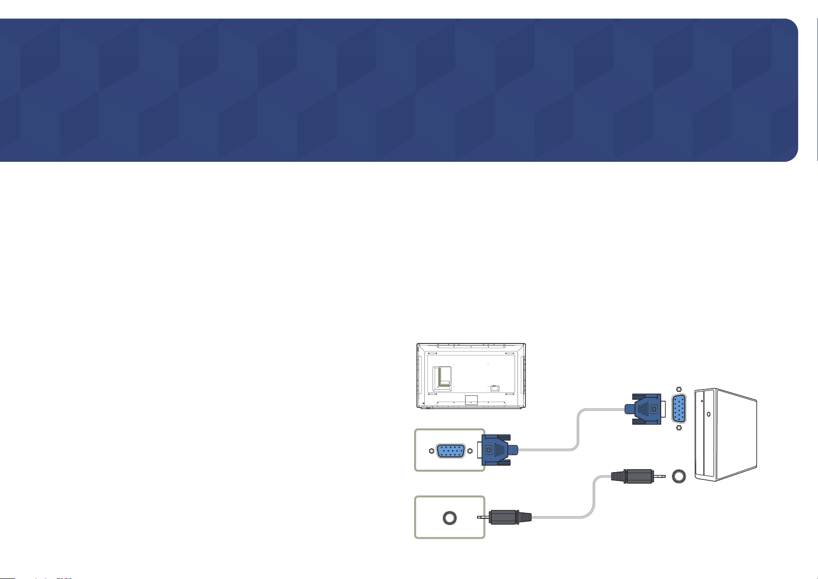
Connection using the D-SUB cable (Analogue type)
―
The appearance may differ depending on the product.
RGB IN
RGB / DVI / HDMI / AV / COMPONENT
AUDIO IN
49
Page 50
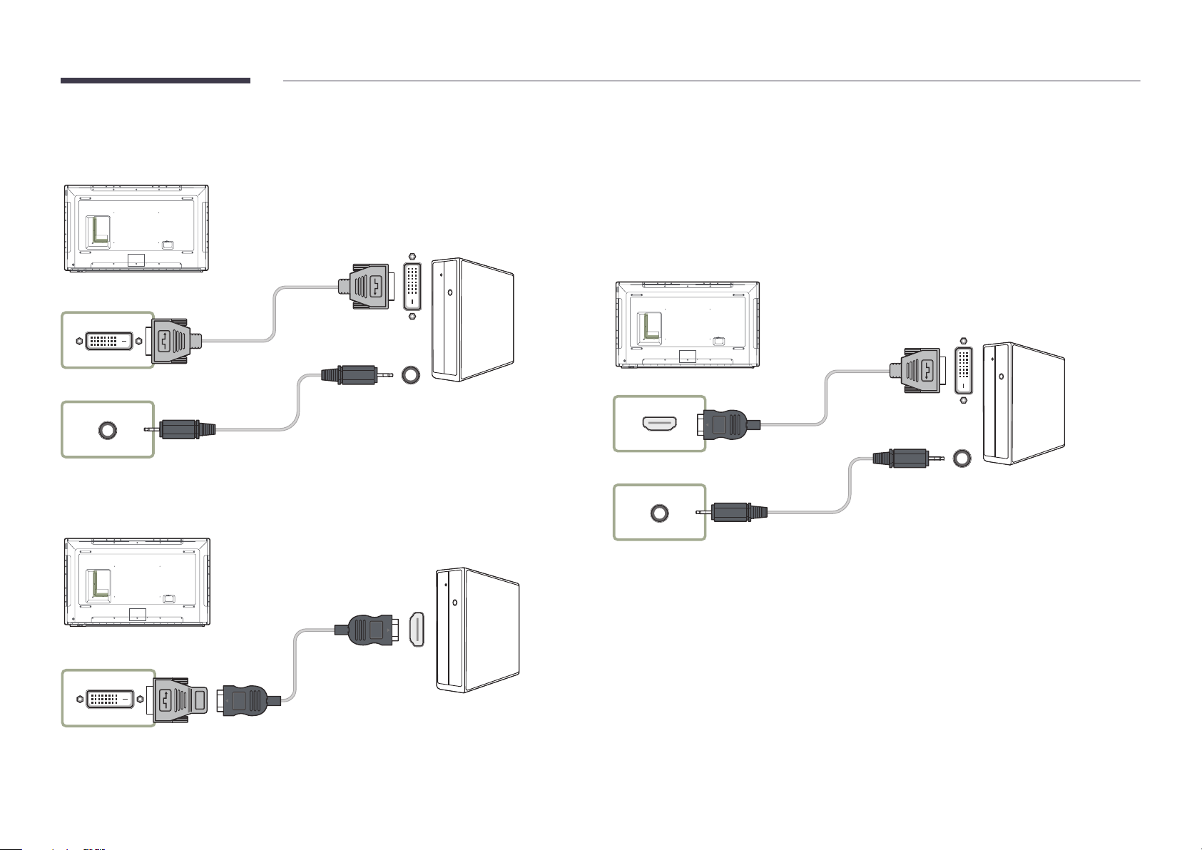
Connection using a DVI cable (Digital type)
DVI /
MAGICINFO IN
RGB / DVI / HDMI / AV / COMPONENT
AUDIO IN
HDMI
DVI /
MAGICINFO IN
Connection Using an HDMI-DVI Cable
―
The appearance may differ depending on the product.
―
You can use the DVI port on the product as an HDMI port by using a DVI-HDMI adapter.
―
The appearance may differ depending on the product.
After connecting a computer to the product with an HDMI-DVI cable, make sure to configure the settings
as shown below to enable the video and audio from the computer.
•
Sound → set HDMI Sound to PC(DVI)
•
Picture → set each screen mode to Tex t under Picture Mode
•
System → General → set HDMI Hot Plug to Off
HDMI IN
RGB / DVI / HDMI / AV / COMPONENT
AUDIO IN
50
Page 51
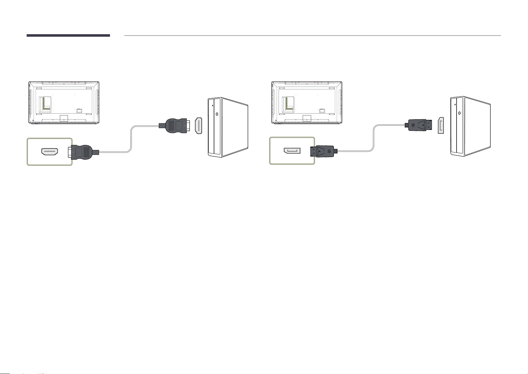
Connection Using an HDMI Cable
Connection Using an DP Cable
―
The appearance may differ depending on the product.
HDMI IN
―
The appearance may differ depending on the product.
DP IN
•
Precautions for using DP
―
To increase the standby power capacity, the product stops DP communication when it is turned
off or in power-saving mode.
If the product in dual monitor mode is turned off or goes into power-saving mode, monitor
setting changes may not be updated. As a result, screen output may not be displayed properly.
In the occurrence of this issue, set Max. Power Saving to Off before using the product.
―
Some graphics cards that are not compliant with the DP standard may prevent the Windows
Booting/Bios screen from being displayed when the product is in power-saving mode. If this is
the case, make sure to turn on the product first before turning on your PC.
―
The DisplayPort interface (DP IN) on the product and the provided DP cable are designed based
on the VESA standards. Using a DP cable that is not VESA compliant may cause the product to
function improperly. Samsung Electronics shall not be held responsible for any issues from using
a cable that is not VESA compliant.
Make sure to use a DP cable that is VESA compliant.
51
Page 52
Connecting to a Video Device
―
The appearance may differ depending on the product.
•
Do not connect the power cable before connecting all other cables.
Ensure you connect a source device first before connecting the power cable.
•
You can connect a video device to the product using a cable.
―
Connecting parts may differ in different products.
―
Press the SOURCE button on the remote control to change the source.
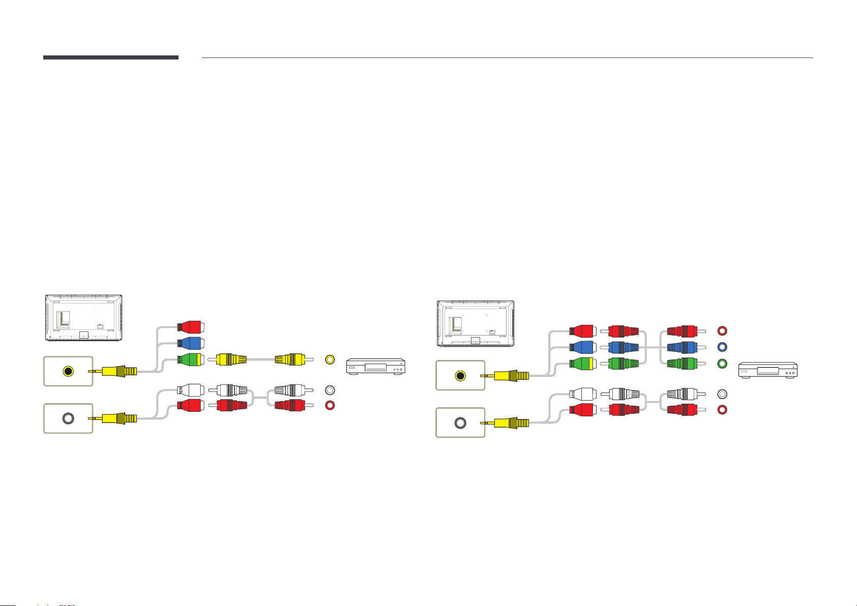
Connection Using the AV Cable
AV IN / COMPONENT IN
RGB / DVI / HDMI / AV / COMPONENT
AUDIO IN
Connection Using the component Cable
AV IN / COMPONENT IN
RGB / DVI / HDMI / AV / COMPONENT
AUDIO IN
52
Page 53
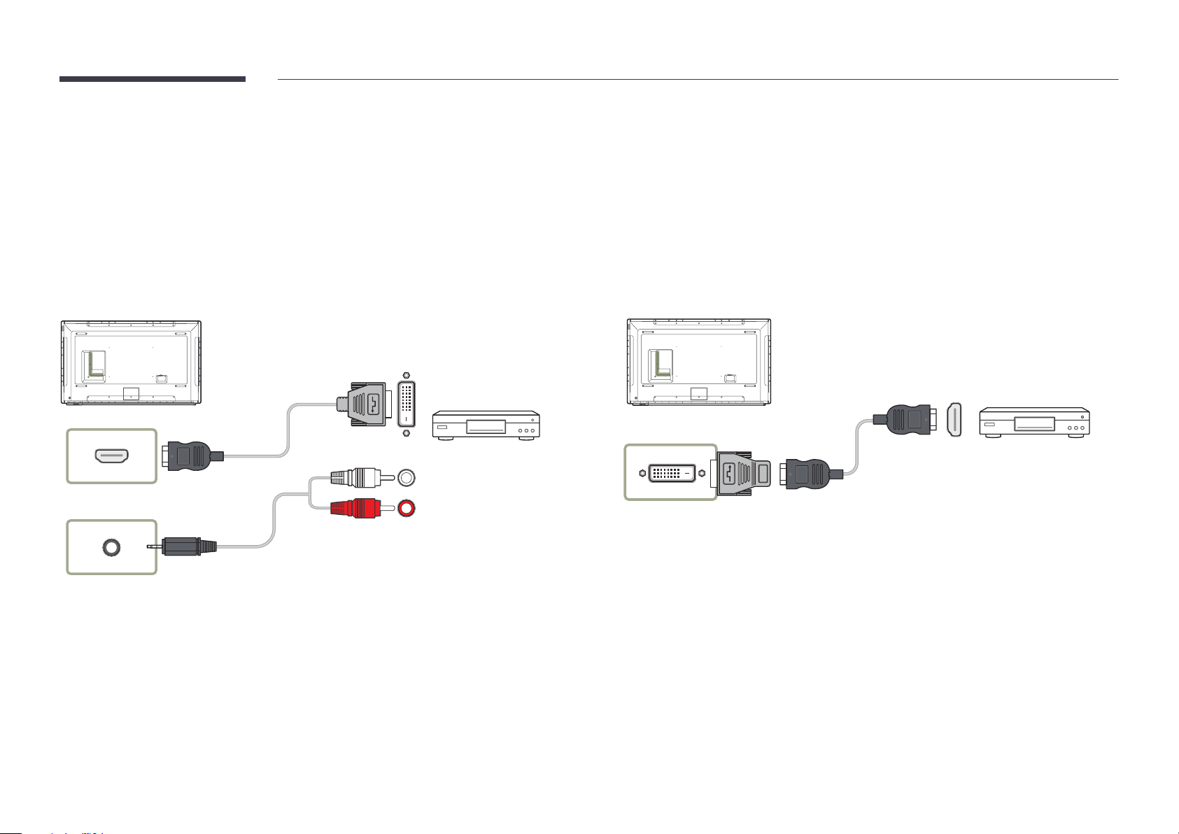
Connection Using an HDMI-DVI Cable
―
The appearance may differ depending on the product.
―
Audio will not be enabled if the product is connected to a video device using an HDMI-DVI cable. To resolve this, additionally connect an audio cable to the audio ports on the product and video device.
―
After connecting a video device to the product with an HDMI-DVI cable, make sure to configure the settings as shown below to enable the video and audio from the video device.
―
Sound → set HDMI Sound to AV(HDMI)
―
Picture → set each screen mode to Videos/Images under Picture Mode
―
System → General → set HDMI Hot Plug to On
―
Supported resolutions include 1080p (50/60Hz), 720p (50/60Hz), 480p, and 576p.
HDMI IN
RGB / DVI / HDMI / AV / COMPONENT
AUDIO IN
DVI /
MAGICINFO IN
HDMI
53
Page 54
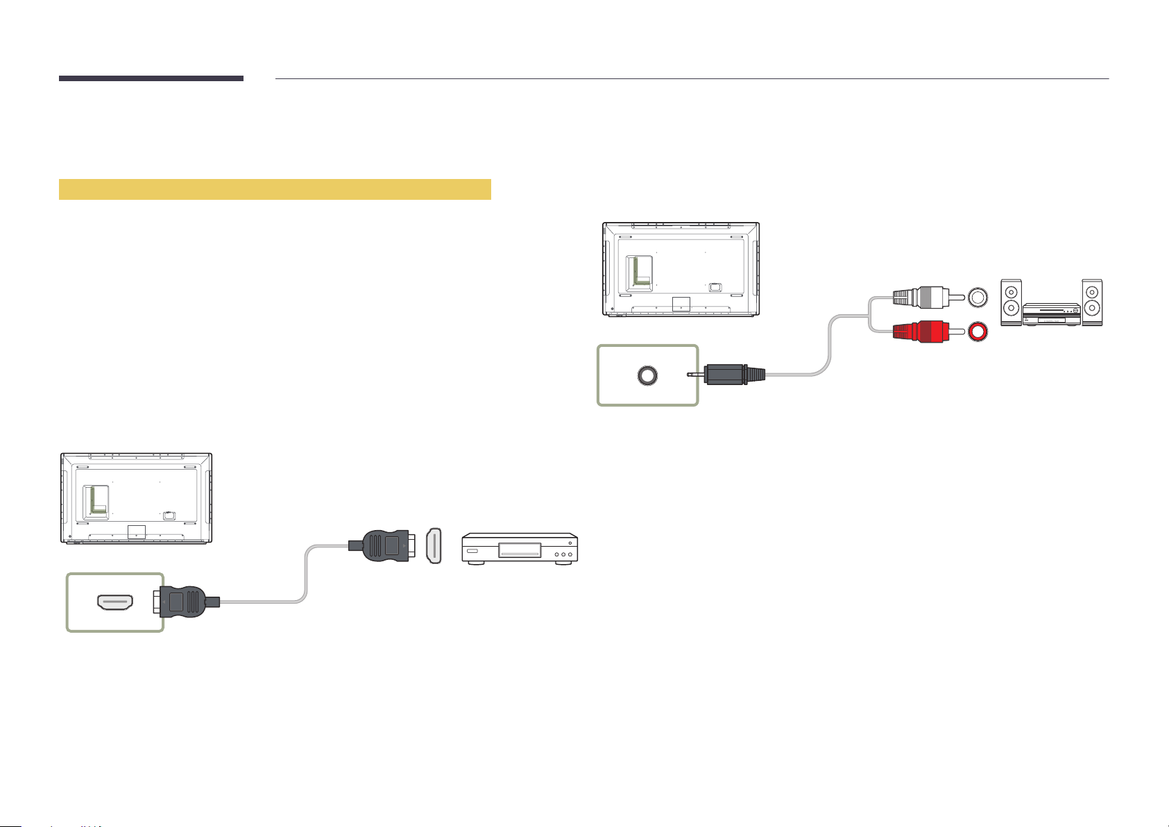
Connection Using an HDMI Cable
―
The appearance may differ depending on the product.
Using an HDMI cable or HDMI to DVI Cable (up to 1080p)
•
For better picture and audio quality, connect to a digital device using an HDMI cable.
•
An HDMI cable supports digital video and audio signals, and does not require an audio cable.
-
To connect the product to a digital device that does not support HDMI output, use an HDMIDVI and audio cables.
•
The picture may not display normally (if at all) or the audio may not work if an external device that
uses an older version of HDMI mode is connected to the product. If such a problem occurs, ask the
manufacturer of the external device about the HDMI version and, if out of date, request an upgrade.
•
Be sure to use an HDMI cable with a thickness of 14 mm or less.
•
Be sure to purchase a certified HDMI cable. Otherwise, the picture may not display or a connection
error may occur.
•
A basic high-speed HDMI cable or one with ethernet is recommended.
This product does not support the ethernet function via HDMI.
Connecting to an Audio System
―
The appearance may differ depending on the product.
―
Connecting parts may differ in different products.
AUDIO OUT
HDMI IN
54
Page 55
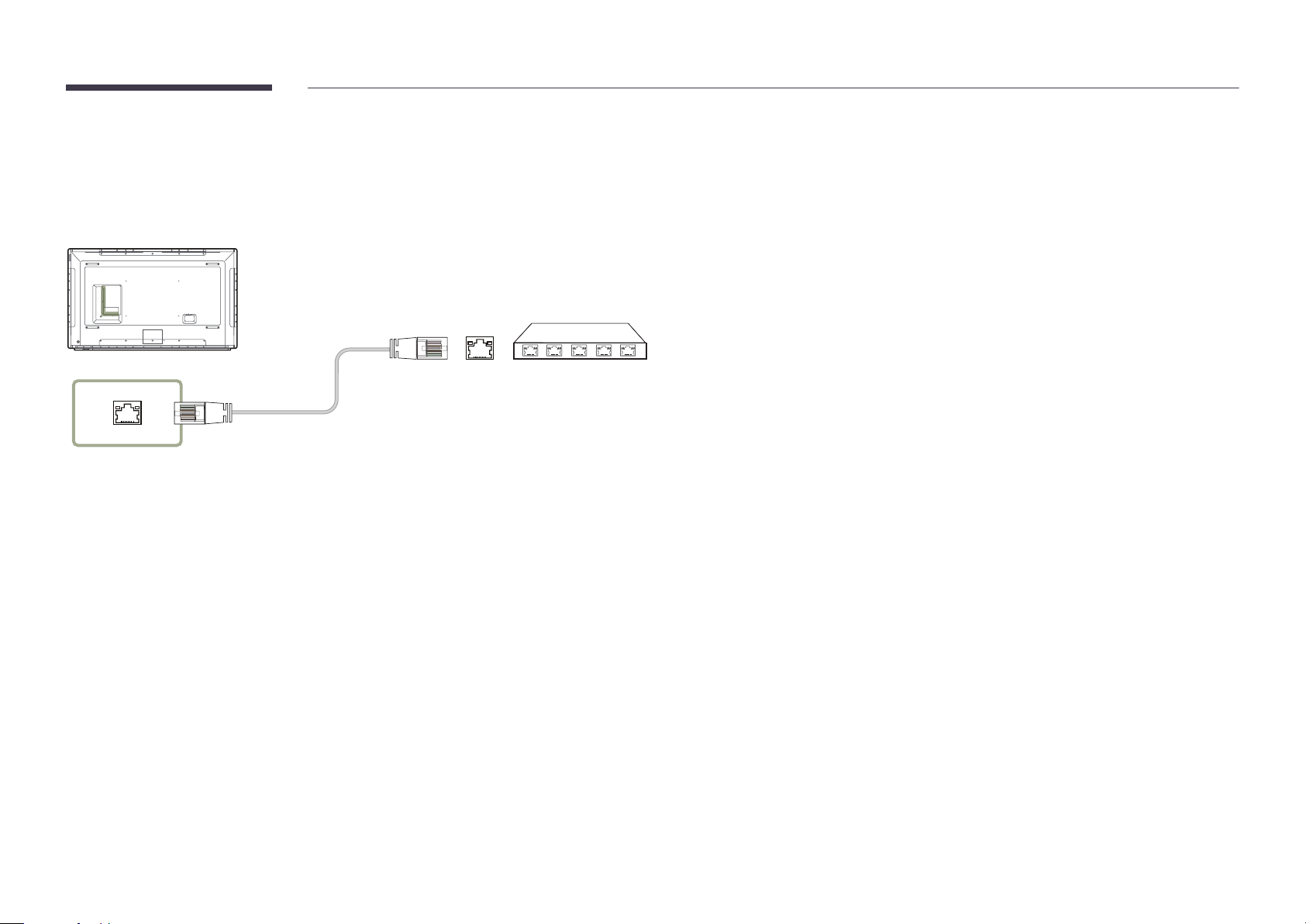
Connecting the LAN Cable
―
The appearance may differ depending on the product.
―
Connecting parts may differ in different products.
RJ45
•
Use Cat7(*STP Type) cable for the connection.
*Shielded Twist Pair.
55
Page 56
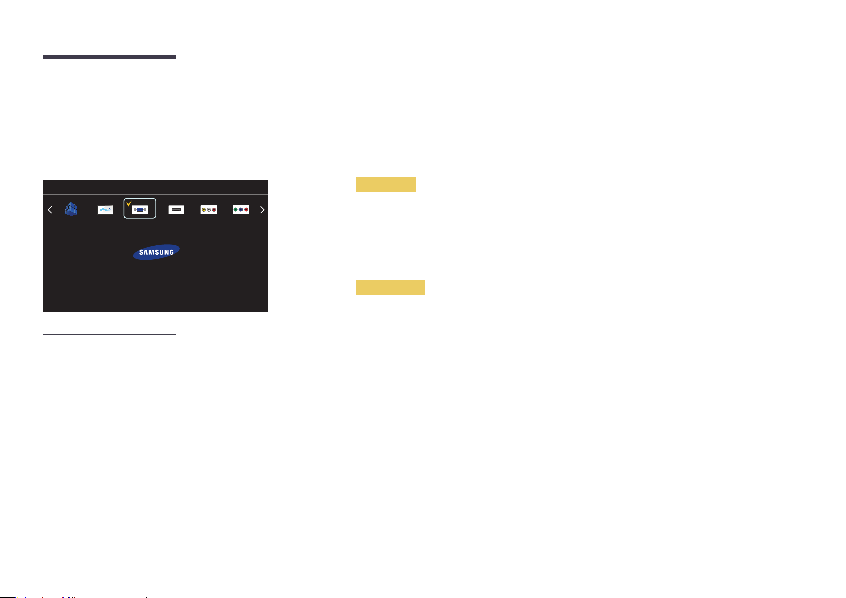
Changing the Input source
Source
SOURCE → Source
Source allows you to select a variety of sources and change source device names.
You can display the screen of a source device connected to the product. Select a source from source list to display the screen
of the selected source.
―
The input source can also be changed by using the SOURCE button on the remote control.
―
The screen may not display correctly if an incorrect source is selected for the source device you want to convert to.
―
To view detailed information about connected source devices, press the TOOLS button from the Source page.
Source
MagicInfo S
-
The displayed image may differ depending on the model.
-
The MagicIWB S software allows you to play a variety of content on a large touchscreen
monitor. Use the software to bring life to your meetings and conferences.
Refer to the touch overlay user guide for details.
The MagicIWB S user guide can be downloaded from http://www.samsung.com/
displaysolutions.
MagicIWB S
To go to Options, press and hold the Enter button.
PC
HDMI ComponentAV
Edit Name
SOURCE → Source → TOOLS → Edit Name → ENTER E
Customize the name of a connected external device.
―
The list can include the following source devices. Source devices on the list differ depending on the selected source.
PC / Cable STB / Satellite STB / PVR STB / Game / Blu-ray / DVD / VCR / AV Receiver / Camcorder / DVI PC / DVI
Devices / TV / IPTV / HD DVD / DMA
Information
SOURCE → Source → TOOLS → Information → ENTER E
You can see detailed information about the selected external device.
56
Page 57

Chapter 04
Using MDC
Multiple display control "MDC" is an application that allows you to easily control multiple display devices simultaneously using a PC.
- For details on how to use the MDC programme, refer to Help after installing the programme. The MDC programme is available on the website.
In the displayed "Ready to Install the Program" window, check the directory path to install the
MDC Programme Installation/Uninstallation
Installation
―
MDC installation can be affected by the graphics card, mother board and network conditions.
Click the MDC Unified installation programme.
1
Select a language for installation. Next, click "OK".
2
When the "Welcome to the InstallShield Wizard for MDC_Unified" screen appears, click "Next".
3
In the "License Agreement" window displayed, select
4
"I accept the terms in the license agreement" and click "Next".
7
programme in and click "Install".
Installation progress will be displayed.
8
Click "Finish" in the displayed "InstallShield Wizard Complete" window.
9
―
Select "Launch MDC Unified" and click "Finish" to run the MDC programme immediately.
The MDC Unified shortcut icon will be created on the desktop after installation.
10
―
The MDC execution icon may not be displayed depending on the PC system or product
specifications.
―
Press F5 if the execution icon is not displayed.
Uninstallation
In the displayed "Customer Information" window, fill out all the information fields and click
5
"Next".
In the displayed "Destination Folder" window, select the directory path you want to install the
6
programme in and click "Next".
―
If the directory path is not specified, the programme will be installed in the default directory
path.
Select Settings > Control Panel on the Start menu and double-click Add/Delete Program.
1
Select MDC Unified from the list and click Change/Remove.
2
57
Page 58
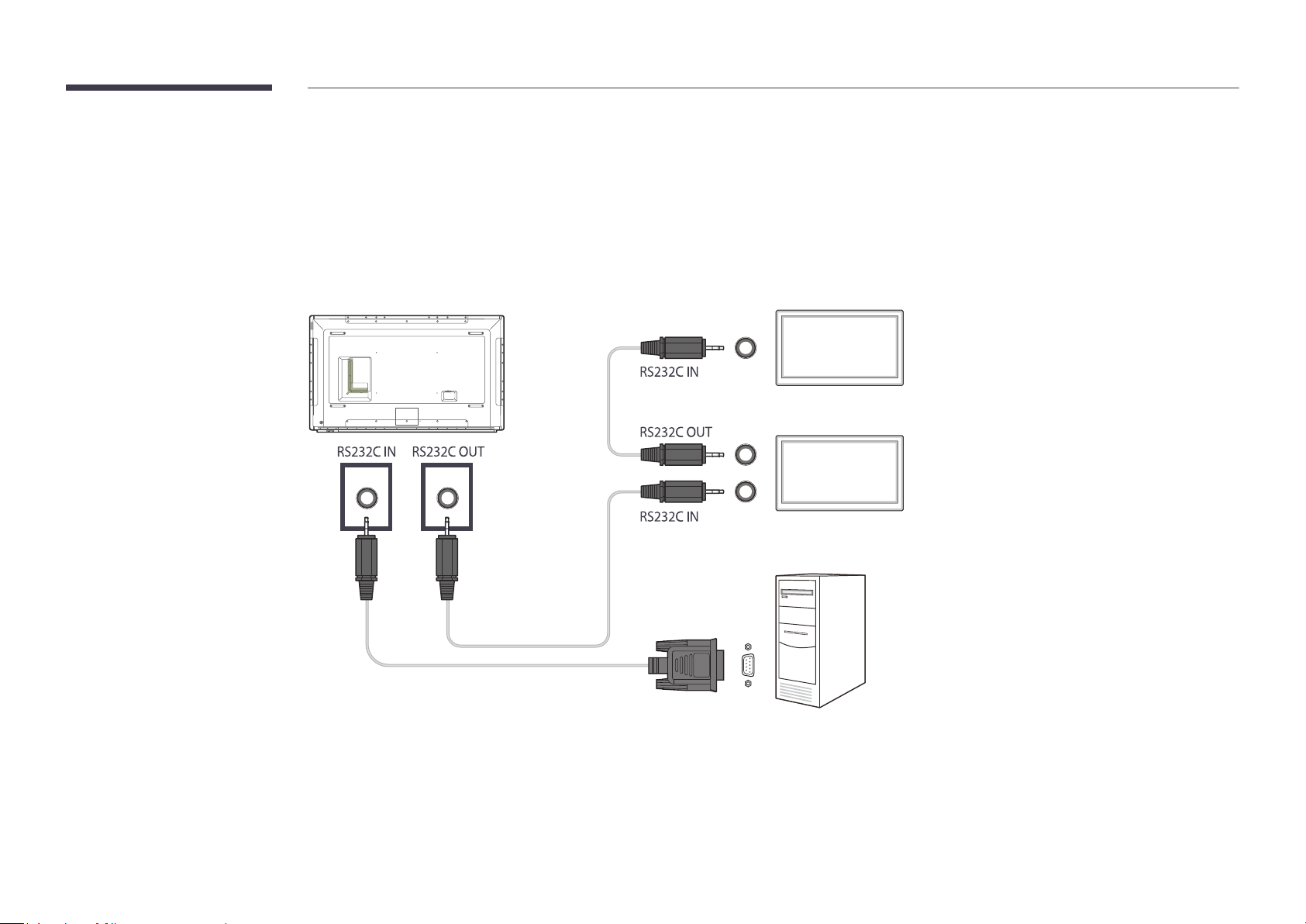
Connecting to MDC
Using MDC via RS-232C (serial data communications standards)
An RS-232C serial cable must be connected to the serial ports on the PC and monitor.
―
The appearance may differ depending on the product.
Monitor 1
Monitor 2
Computer
58
Page 59
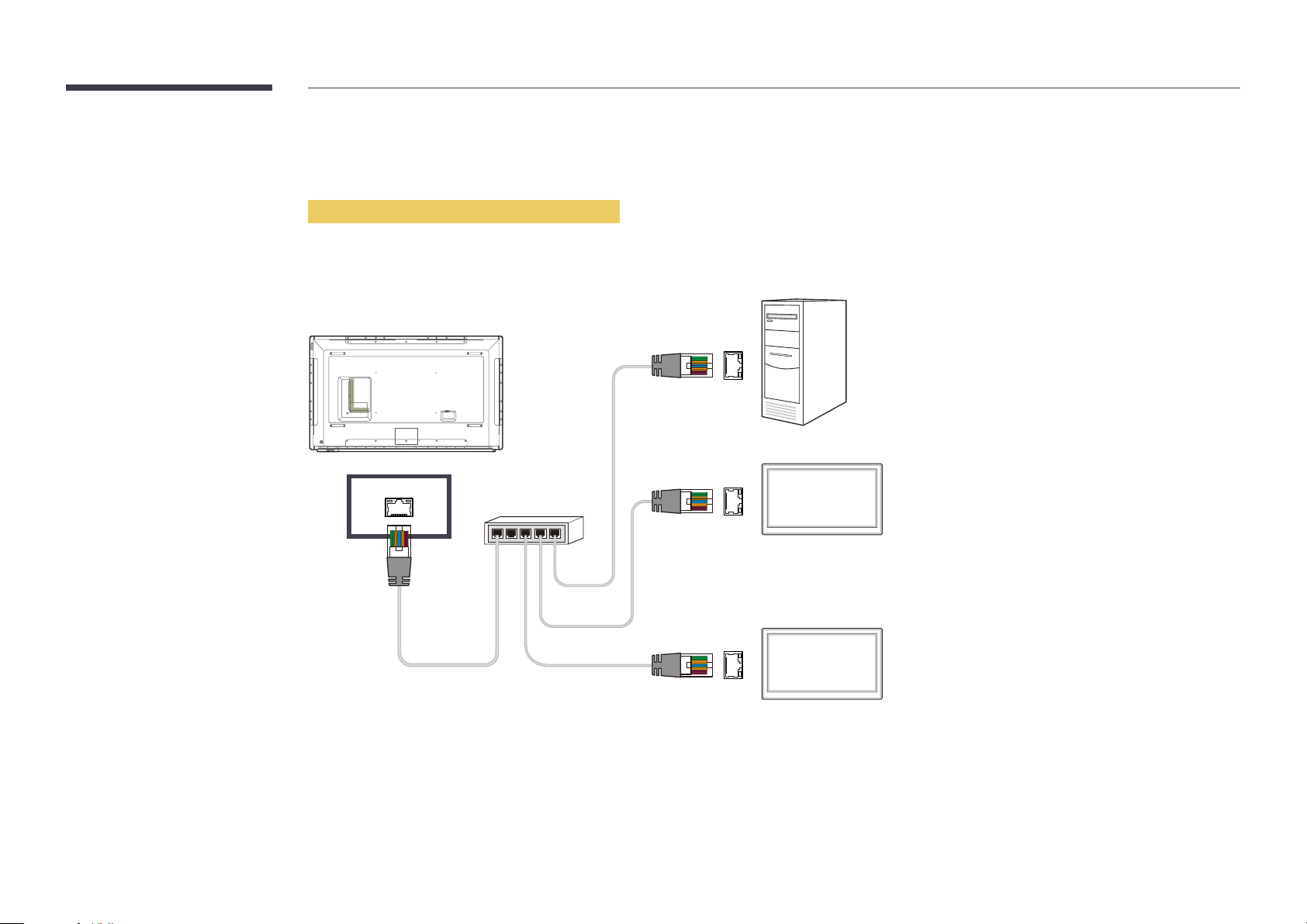
Using MDC via Ethernet
Enter the IP for the primary display device and connect the device to the PC. Display devices can be connected to each other using a LAN cable.
Connection using a direct LAN cable
―
The appearance may differ depending on the product.
―
Multiple products can be connected using the RJ45 port on the product and the LAN ports on the HUB.
Computer
RJ45
HUB
Monitor 1
Monitor 2
59
Page 60
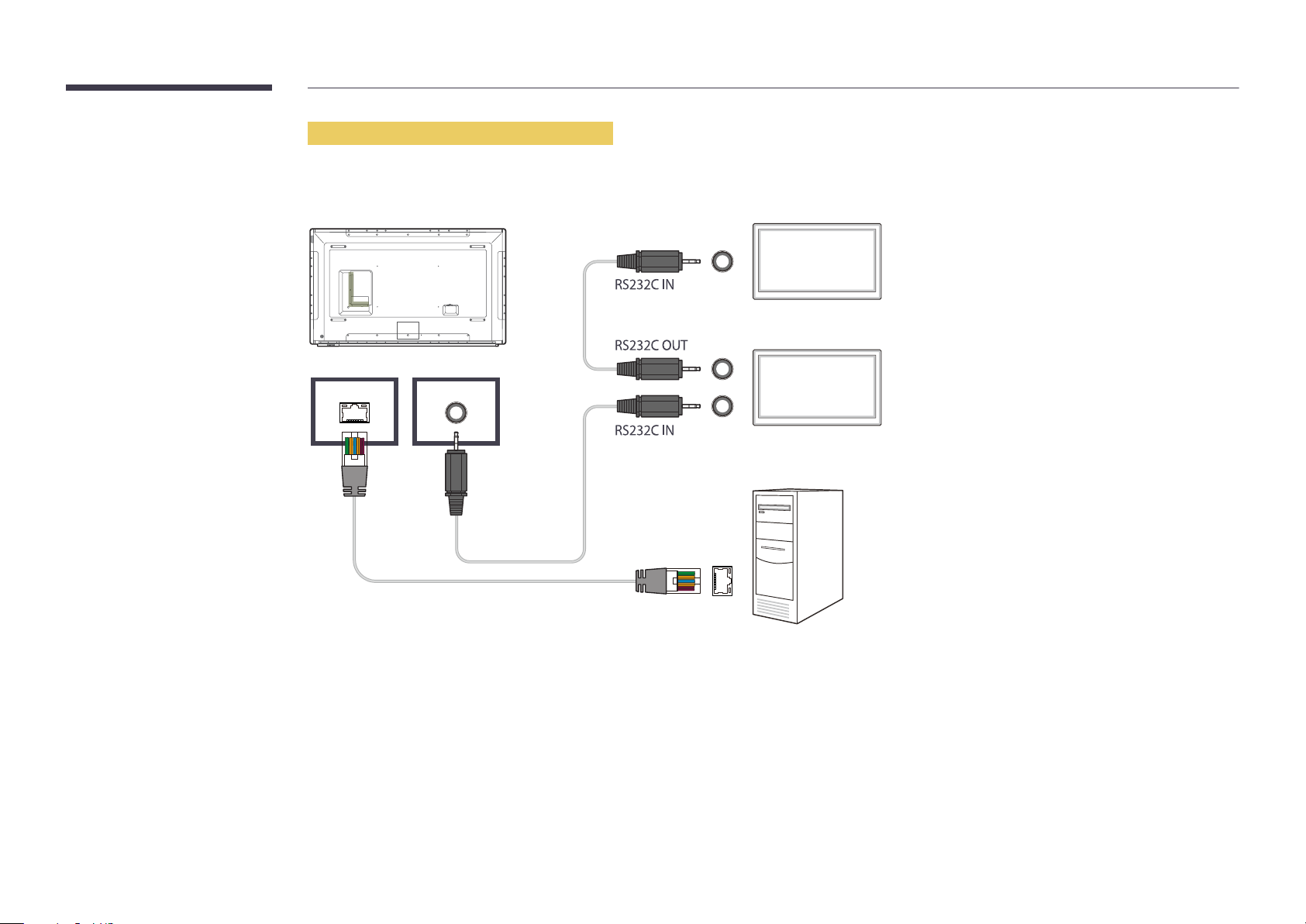
Connection using a cross LAN cable
―
The appearance may differ depending on the product.
―
Multiple products can be connected using the RS232C IN / OUT port on the product.
RS232C OUTRJ45
Monitor 1
Monitor 2
Computer
60
Page 61
Chapter 05
Home feature
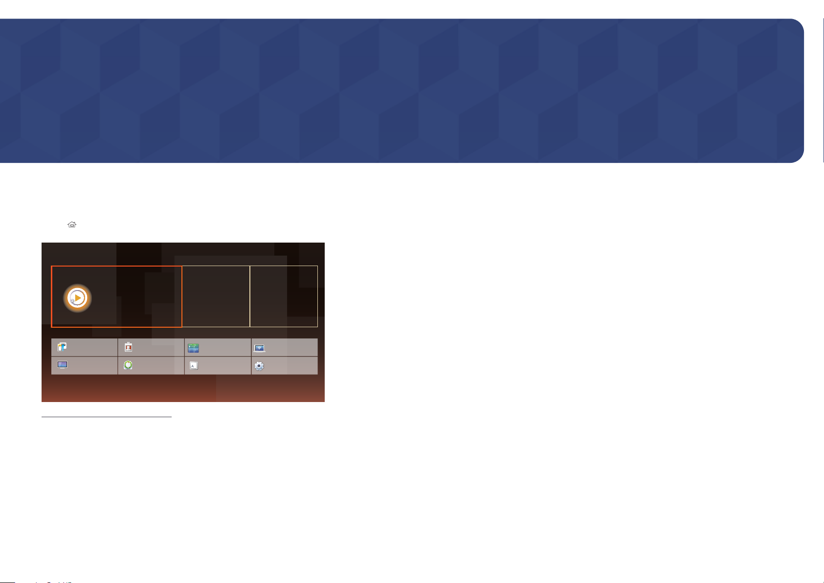
This feature is provided in Support → Go to Home.
Accessible using the HOME button on the remote control.
Player
HOME → Player → ENTER E
―
To use the Player feature, set Play via to MagicInfo in System.
Play a range of content such as channels with schedules assigned, templates or files.
Play channels or content using any of the following methods.
•
Network Channel: Play content using the server.
―
To run Network Channel, make sure the product is connected to the server.
•
Local Channel: Play content in internal memory or from external memory.
Player
Play a variety of content, such as
scheduled channels, templates or files.
Clone Product
Picture Mode
-
The displayed image may differ depending on the model.
ID Settings
On/Off Timer
Schedule Template
Video Wall
Ticker
Network Status
More settings
61
Page 62
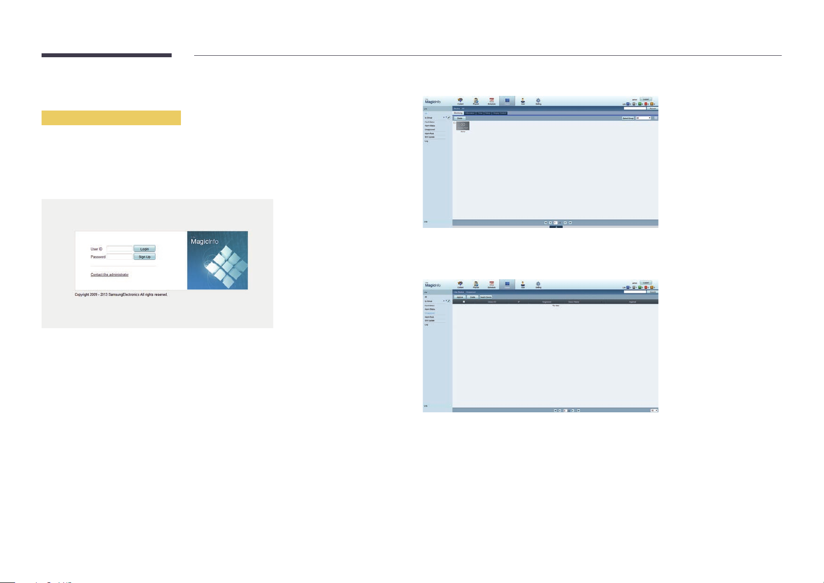
Approving a connected device from the server
Approving the Lite server
•
Set MagicInfo Mode to Lite in Server Network Settings.
Approve and use the Lite server now.
―
First configure the server Network Settings before device approval.
Access the server you have assigned to your device.
1
Enter your ID and password to log in.
2
Select Device from the top menu bar.
3
Select Lite from the menus on the left.
4
Select Unapproved from the sub-menus of Lite.
5
Select the Approve button for your device from the list of unapproved Lite devices.
6
62
Page 63
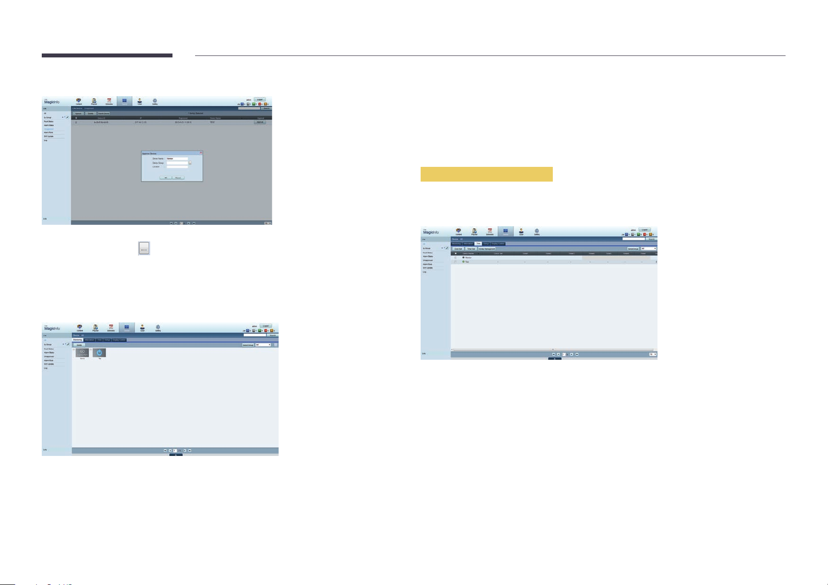
Enter the information required to approve the device.
7
•
Device Name: Enter the device name.
•
Device Group: Select
•
Location: Enter the current location of the device.
―
Pressing the INFO button on the remote when a network schedule is running will display the details of
the schedule. Check that the correct device has been selected by viewing the device ID in the details.
Select the All menu to check that the device has been registered.
8
to specify the group.
When the device is approved by the server, the schedule registered in the selected group will be
9
downloaded to the device. The schedule will run after it is downloaded.
―
For further details on how to configure a schedule, refer to the <MagicInfo Lite Server user's manual>.
―
If a device is deleted from the list of devices approved by the server, the device will reboot to reset its
settings.
Setting the current time
A schedule may not run if the time set on the device is different from the server's current time.
Go to the tabs Device → Time.
1
Select your device.
2
Select Clock Set, and sync the time with the server.
3
•
When connecting to the server for the first time, the time on the product is set using the GMT time
of the region where the server is installed.
•
The time on the product can be changed from the server as shown in step 3.
•
Turning the product off and then on again will restore the time setting on the product to the last
time that was set from the server.
―
For further details on how to manage the time (scheduling, holiday management, etc.), refer to the
<MagicInfo Lite Server user's manual>.
63
Page 64
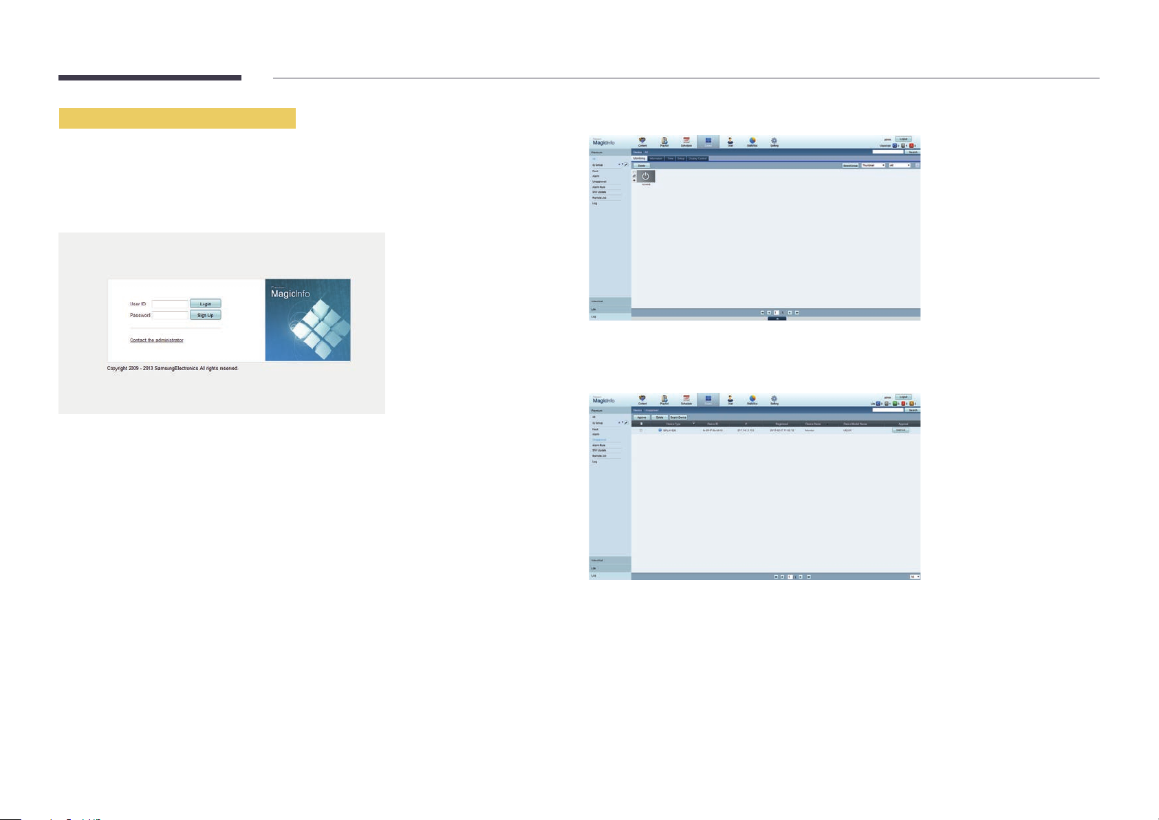
Approving the Premium server
•
Set MagicInfo Mode to Premium in Server Network Settings.
Approve and use the Premium server now.
―
First configure the server Network Settings before device approval.
Access the server you have assigned to your device.
1
Enter your ID and password to log in.
2
Select Device from the top menu bar.
3
Select Premium from the menus on the left.
4
Select Unapproved from the sub-menus of Premium.
5
Select the Approve button for your device from the list of unapproved Premium devices.
6
64
Page 65
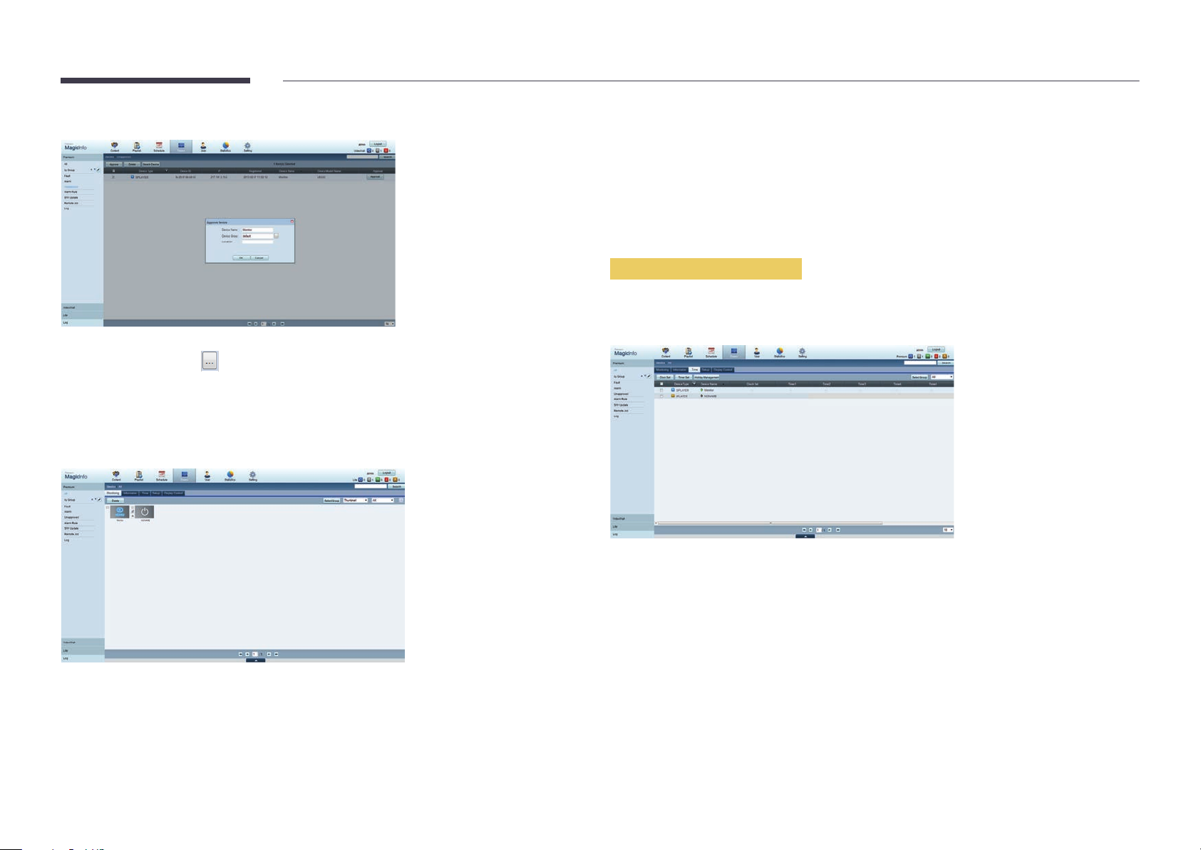
Enter the information required to approve the device.
7
•
Device Name: Enter the device name.
•
Device Group: Select
•
Location: Enter the current location of the device.
―
Pressing the INFO button on the remote when a network schedule is running will display the details of
the schedule. Check that the correct device has been selected by viewing the device ID in the details.
Select the All menu to check that the device has been registered.
8
to specify the group.
When the device is approved by the server, the schedule registered in the selected group will be
9
downloaded to the device. The schedule will run after it is downloaded.
―
For further details on how to configure a schedule, refer to the <MagicInfo Premium Server user's
manual>.
―
If a device is deleted from the list of devices approved by the server, the device will reboot to reset its
settings.
Setting the current time
A schedule may not run if the time set on the device is different from the server's current time.
Go to the tabs Device → Time.
1
Select your device.
2
Select Clock Set, and sync the time with the server.
3
•
When connecting to the server for the first time, the time on the product is set using the GMT time
of the region where the server is installed.
•
The time on the product can be changed from the server as shown in step 3.
•
Turning the product off and then on again will restore the time setting on the product to the last
time that was set from the server.
―
For further details on how to manage the time (scheduling, holiday management, etc.), refer to the
<MagicInfo Premium Server user's manual>.
65
Page 66
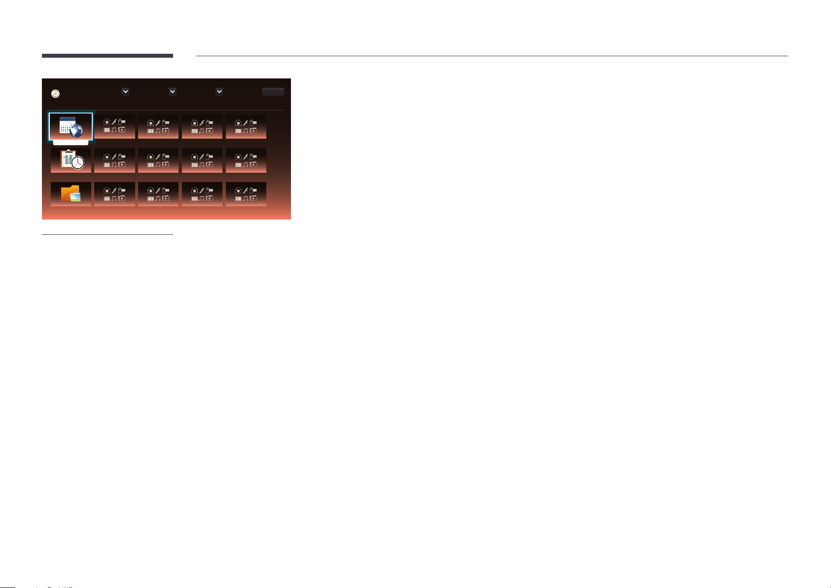
Player
Browse and play content stored on the selected device.
No channels
Network Channel
No channels
Local Channel
My Templates
Device : All Content : All Sort by : File Name
Options
1 / 4 item(s)
Network Channel
Play content, templates and schedules configured on the server.
•
You can view whether the server is connected (approval) in the Player menu screen.
To view whether the server is connected when a Network Channel is running, press INFO on the remote.
Select Network Channel from the Player menu.
1
―
The No channels message appears if no channel has been registered in Network Channel.
Network Channel will run.
2
-
The displayed image may differ depending on the model.
Local Channel
Play a schedule or channel that was configured in the product.
Select Local Channel from the Player menu.
1
―
The No channels message appears if no channel has been registered in Local Channel.
Local Channel will run.
2
My Templates
Play a template in My Templates stored in the internal memory of the product.
66
Page 67
Available features in the Player page
The Player list page provides the following features.
•
Device
Select either Internal or USB to search for a desired device list.
-
All / Internal / USB
•
Content
Select a content type as criterion to search for a desired content list.
-
All / Video / Image / PDF / Flash / Office / My Templates
•
Sort by
Specify the content sort criterion.
-
File Name / Recently played
•
Options
Menu items in the Player page
Option Name Operations
Play Selected
Send
Delete
Settings
Select and play desired content.
Copy content to another storage device.
Delete desired content.
Configure detailed properties of content.
―
See the following page for details on the Settings feature.
67
Page 68
Player page Settings menu
Settings
Settings
Select the storage location that you want to download scheduled channels
from the network to.
Default Storage
Picture Size
Display Duration
Transition Effect
Content Orientation
-
The displayed image may differ depending on the model.
Internal
Random
Landscape
Close
Default Storage
Select the storage location that you want to download scheduled channels from the network to.
•
Internal / USB / SD Card (The DM65E-BR and DM75E-BR models are not supported.)
Picture Size
Set the screen size for content.
If Picture Size is set to Video or Image
•
Full Screen / Original Size / Fit to Screen
If Picture Size is set to PDF or Office
•
Full Screen / Original Size
―
This feature is only available for Video, Image, PDF and Office files.
Display Duration
Set the duration for each page in a slideshow.
―
This feature is only available for Image, PDF, Flash and Office files.
Transition Eect
Configure transition effects between pages or scenes in a slideshow or video file.
•
None / Fade1 / Fade2 / Blind / Spiral / Checker / Linear / Stairs / Wipe / Random
―
This feature is only available for Image files.
Content Orientation
Switch the orientation of playing content to Landscape or Portrait mode.
•
Landscape / Portrait
―
If Content Orientation is Portrait view, it does not support VP8 video codec.
―
Source is not available when Content Orientation is set to Portrait.
68
Page 69

Default content
This default content will be displayed if you run a channel while no Programmes are scheduled on the channel.
•
None / My Templates
Safely Remove
Safely removes USB memory
Reset
Restore all the values under Settings to the default when the product was purchased.
69
Page 70
When Content is Running
Viewing the details of the content that is running
Information
Current time:
Type:
CH Number:
CH Name:
Software Version:
No Schedule to download
-
The displayed image may differ depending on the model.
DTP-EP-APP-5402-03-Hijack
00:00am
Network Channel
No channels selected
No channels selected
OK
Press the INFO button on the remote control.
•
Current time
•
Type : Type of channel currently playing
―
Only applicable during Network Channel / Local Channel playback.
•
CH Number: Number assigned to the channel currently playing
―
Only applicable during Network Channel / Local Channel playback.
•
CH Name: Name of the channel currently playing
―
Only applicable during Network Channel / Local Channel playback.
•
Software Version: Displays the software version of a device
•
MAC ID: Displays the original identification number of a device
•
Tags: Tag settings assigned to a device from the server
―
Only applicable during Network Channel / Local Channel playback.
•
Server: Displays the connection status (Connected, Not connected or Not approved) of the server
•
USB: Displays the connection status of a USB device
70
Page 71
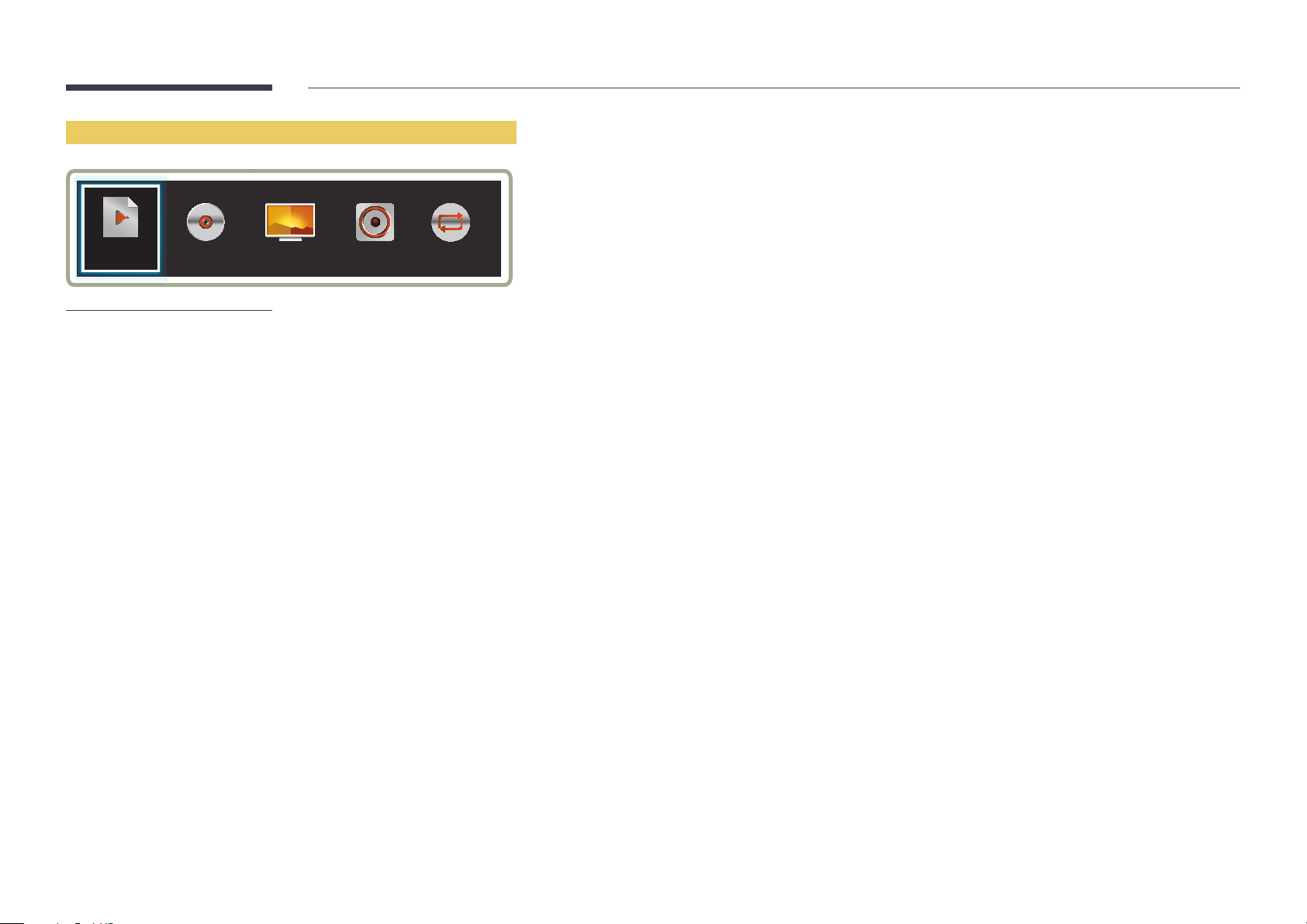
Changing the settings for the content that is running
Playlist Picture Mode Sound Mode Repeat
-
The displayed image may differ depending on the model.
-
This feature is not available when content is playing through Video Wall.
Music
Press the TOOLS button on the remote control during content playback to configure settings such as Picture Mode and
Sound Mode.
•
Playlist
View a list of content items currently playing.
•
Music
Set the background music for the content currently playing.
•
Picture Mode
Customizes the screen settings for the content currently playing
-
Shops & Malls / Offices & Schools / Terminals & Stations / Video Wall / Calibration
•
Sound Mode
Customizes the audio settings for the content currently playing
-
Standard / Music / Movie / Clear Voice / Amplify
•
Repeat
Set the repeat mode.
-
One / All
71
Page 72
File Formats Compatible with Player
•
Supported file systems include FAT32 and NTFS.
•
A file with a vertical and horizontal resolution larger than the maximum resolution cannot be
played.
Check the vertical and horizontal resolution of the file.
•
Check the supported video and audio Codec types and Versions.
•
Check the supported file versions.
-
Flash player 11.0 and older and Flash Air 3.0 and older versions are supported.
-
PowerPoint version up to 97 – 2007 is supported
•
Only the last USB device that was connected is recognized.
Template files and LFD(.lfd) files
Restrictions
•
Ensure a distributed folder (content / schedules) exists in Internal / USB memory.
Playback restrictions
•
A maximum of two video (Video) files can be played.
•
More than one Flash file cannot be played.
•
For Office files (PPT and Word files) and PDF files, only one file type is supported at a time.
•
Multiple videos (Video) cannot be played on a single display of a video wall simultaneously.
Network Schedule Multiframe
Playback restrictions
•
A maximum of two video files (Video) can be played simultaneously.
•
In portrait playback mode, only one video file can be played at a time.
•
More than one Flash file cannot be played.
•
For Office files (PPT and Word files) and PDF files, only one file type is supported at a time.
•
LFD(.lfd) files are not supported.
Sound output restrictions
•
More than one sound output cannot be used.
•
Playback priority: Flash file > network BGM > local BGM > video file in the main frame selected
by the user
―
Network BGM: Settings can be configured in step 1 when creating a server schedule.
―
Local BGM: BGM settings can be configured using the tools displayed after the TOOLS button
is pressed during Player playback.
―
User-selected main frame: Main frame settings can be configured in step 2 when creating a
server schedule.
Sound output restrictions
•
More than one sound output cannot be used.
•
Playback priority: Flash file > network BGM > local BGM > video file in the main frame selected
by the user
72
Page 73
Contents
File Extension Container Video Codec Resolution Frame rate
(fps)
*.avi
*.mkv
*.asf
*.wmv
*.mp4
*.mov
*.3gp
*.vro
*.mpg
*.mpeg
*.ts
*.tp
*.trp
*.v
*.vob
*.svi
*.m2ts
*.mts
*.divx
AVI
MKV
ASF
MP4
3GP
VRO
VOB
PS
TS
DivX 3.11 / 4.x / 5.x / 6.x 1920 x 1080 6~30 30
MPEG4 SP / ASP
H.264 BP / MP / HP
Motion JPEG
Window Media Video v9
MPEG2
MPEG1
VP6 640 x 480 4
Bit rate
(Mbps)
Audio Codec
AC3
LPCM
AAC
HE-AAC
WMA
DD+
MPEG(MP3)
DTS Core
G.711(ALaw,μ-Law)
73
Page 74
Video Audio Image
•
3D video is not supported.
•
Content with a resolution larger than the resolution
specified in the table above is not supported.
•
Video content with a Bit rate or Frame rate larger than
the rate specified in the table above can cause choppy
video during playback.
•
Video content will not play, or not play correctly, if
there is an error in the content or the container.
•
Some USB/digital camera devices may not be
compatible with the player.
•
Supports up to H.264, Level 4.1
•
H.264 FMO / ASO / RS, VC1 SP / MP / AP L4 and AVCHD
are not supported.
•
For all Video codecs except MVC, VP8, VP6:
-
Below 1280 x 720: 60 frame max
-
Above 1280 x 720: 30 frame max
•
GMC 2 or higher is not supported.
•
Supports only BD MVC Spec.
•
Only one video file can play at a time if video files on
the monitor use incompatible codecs or the resolution
is 1080 x 1920.
•
When a single video file is playing, Seamless mode is
not supported under the following conditions:
-
Incompatible codec (MVC, VP3, MJPEG) ↔
Incompatible codec
-
Incompatible codec ↔ Compatible codec
-
The resolution is different from that of the monitor
-
The frequency is different from that of the monitor
•
Audio content with a Bit rate or Frame rate
larger than the rate specified in the table
above can cause choppy audio during
playback.
•
Video content will not play, or not play
correctly, if there is an error in the content
or the container.
•
Some USB/digital camera devices may not
be compatible with the player.
•
Supports up to WMA 10 Pro 5.1 channel.
WMA lossless audio is not supported.
•
QCELP, AMR NB/WB are not supported.
•
•
•
•
Compatible image file format : JPEG, PNG, BMP
-
32-bit, 24-bit and 8-bit BMP files are
supported.
Supported maximum resolution : 4096 x 4096
Supported maximum file size: 20MB
Supported image effects : 9 effects
(Fade1, Fade2, Blind, Spiral, Checker, Linear,
Stairs, Wipe, Random)
74
Page 75
Flash Power Point PDF
•
Flash player 11.0 and older and Flash Air 3.0 and
older versions are supported.
•
Flash Animation
-
Compatible file format : SWF
•
Recommended resolution : 960 x 540
-
Caution
Performance comparable to Flash Player
on a Windows operating system cannot be
guaranteed
Optimization is needed during content
creation
•
Flash Video
-
Compatible file format : FLV
-
Video
Codec : H.264 BP
Resolution : 1920 x 1080
-
Audio
Codec : H.264 BP
-
Caution
F4V file format is not supported
Screen Video is not supported
•
Compatible document file formats
-
Extension : ppt, pptx
-
Version : Office 97 ~ Office 2007
•
Functions not supported
-
Animation effect
-
3D shapes (which will be displayed in 2D)
-
Header and footer (some subitems are not
supported)
-
Word Art
-
Align
A group alignment error may occur
-
Office 2007
SmartArt is not fully supported. 97 out of
115 subitems are supported.
-
Object insertion
-
Half-width characters
-
Letter spacing
-
Charts
-
Vertical text
some subitems are not supported
-
Slide notes and handout
•
•
Compatible document file formats
-
Extension : pdf
Functions not supported
-
Content less than 1 pixel not supported
because of performance degradation issue.
-
Masked Image, Tiled Image content not
supported.
-
Content with Rotated Text, not supported.
-
3D Shadow Effects not supported.
-
Some characters not supported
(Special characters may be corrupted)
75
Page 76
WORD Template les LFD
•
Compatible document file formats
-
Extension : .doc, .docx
-
Version : Office 97 ~ Office 2007
•
Functions not supported
-
Page background effect
-
Some paragraph styles
-
Word Art
-
Align
A group alignment error may occur
-
3D shapes (which will be displayed in 2D)
-
Office 2007
SmartArt is not fully supported. 97 out of
115 subitems are supported.
-
Charts
-
Half-width characters
-
Letter spacing
-
Vertical text
some subitems are not supported
-
Slide notes and handout
•
Creation/editing/playback are only available in
Template.
•
Supported in Network Channel and Local
Channel
•
Compatible document file formats
-
Extension : .lfd
76
Page 77
File Formats Compatible with Videowall
―
Refer to the <MagicInfo Server user's manual> for further details.
Video Image
•
3D video is not supported.
•
Content with a resolution larger than the resolution specified in the table
above is not supported.
•
Video content with a Bit rate or Frame rate larger than the rate specified in
the table above can cause choppy video during playback.
•
Video content will not play, or not play correctly, if there is an error in the
content or the container.
•
Some USB/digital camera devices may not be compatible with the player.
•
Supports up to H.264, Level 4.1
•
H.264 FMO / ASO / RS, VC1 SP / MP / AP L4 and AVCHD are not supported.
•
For all Video codecs except MVC, VP8, VP6:
-
Below 1280 x 720: 60 frame max
-
Above 1280 x 720: 30 frame max
•
GMC 2 or higher is not supported.
•
Supports only BD MVC Spec.
•
Some codecs may not be supported in portrait playback mode.
•
•
Compatible image file format : Jpeg, bmp, png
Supported maximum resolution : 15,360 x 8,640
―
A higher resolution image may take longer to display on the screen.
77
Page 78
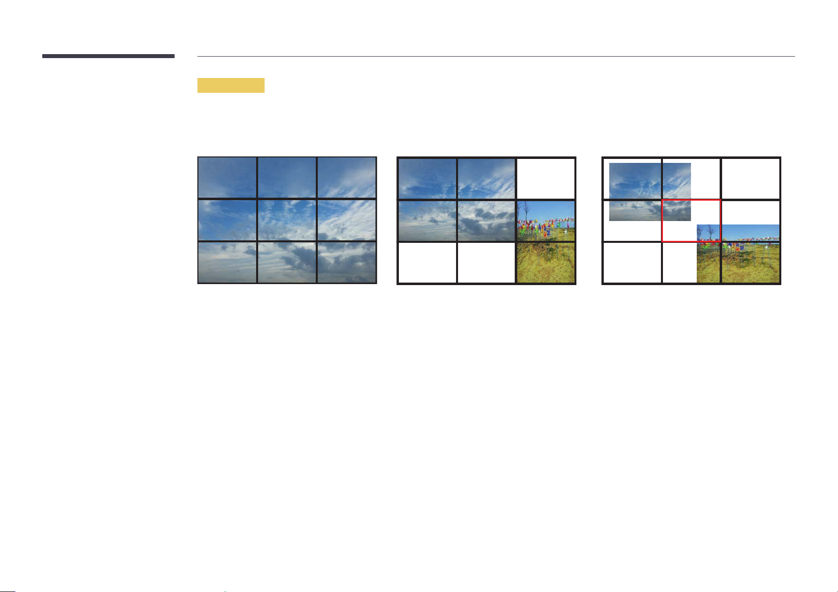
Restrictions
•
Only one video (Video) file can be played per client.
―
Different content files can be played on the displays of a video wall.
Two video (Video) files cannot be played on a single display of a video wall.
Available
Available Not available
78
Page 79
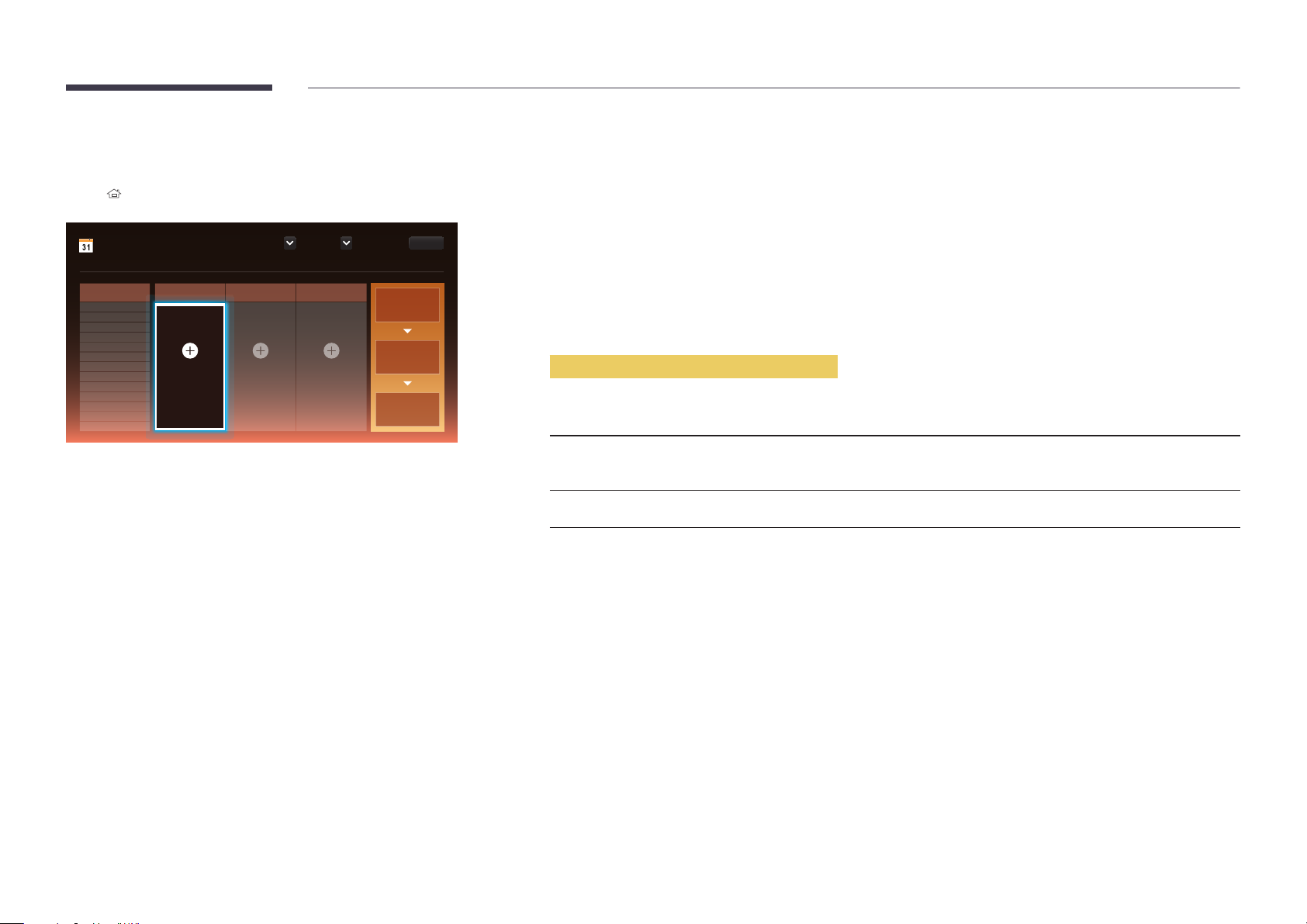
Schedule
HOME → Schedule → ENTER E
Schedule
Schedule your content on a local channel or edit existing channels.
Playing Time
12:00 am
12:30 am
01:00 am
01:30 am
02:00 am
02:30 am
03:00 am
03:30 am
04:00 am
04:30 am
05:00 am
05:30 am
06:00 am
[CH1]Channel 1 [CH2]Channel 2 [CH3]Channel 3
+ Add Programme Schedule your content on
CH 2.
Schedule your content on
CH 3.
OptionsType : Local Device : Internal
Add content to create
a programme on the
channel.
Configure the display
duration to set how
long each item of
content will play for.
Set a start time and
a stop time for the
programme.
Available features in the Schedule page
The Schedule page provides the following features.
•
Type
-
Local: Add or edit schedules.
-
Network: View the network schedule configured on the server.
•
Device
-
Display the name of a connected storage device.
―
This option only activates if Type is set to Local in Device.
•
Options
Menu items in the Schedule page
Option Name Operations
Send
Send configured schedules to another storage device. This is similar to the "copy" feature
on PCs.
Delete
Delete schedules.
79
Page 80
Configuring channel schedules
Play media content such as videos, photos and music at a desired time.
Select a channel to configure.
1
Select video, music and photo content you want to apply to the channel schedule.
2
Set the time to play the schedule. (Start Time ~ Stop Time)
3
Change the channel schedule name, and then select a destination folder to save to.
4
Press the Save button.
5
―
Only applicable when Type is set to Local.
Editing a channel schedule.
Change settings for a configured channel schedule such as content, the duration and the schedule name.
Select a channel to edit.
1
Select video, photo or music content to edit in the channel schedule.
2
-
Deleting content: Place the cursor over the desired content and then press the E button to delete it.
-
Move to the far right end of the content list. Click the + button to add content or change the playback order of content items.
Set the time to play the schedule. (Start Time ~ Stop Time)
3
Change the channel schedule name, and then select a destination folder to save to.
4
Press the Save button.
5
―
Only applicable when Type is set to Local.
80
Page 81
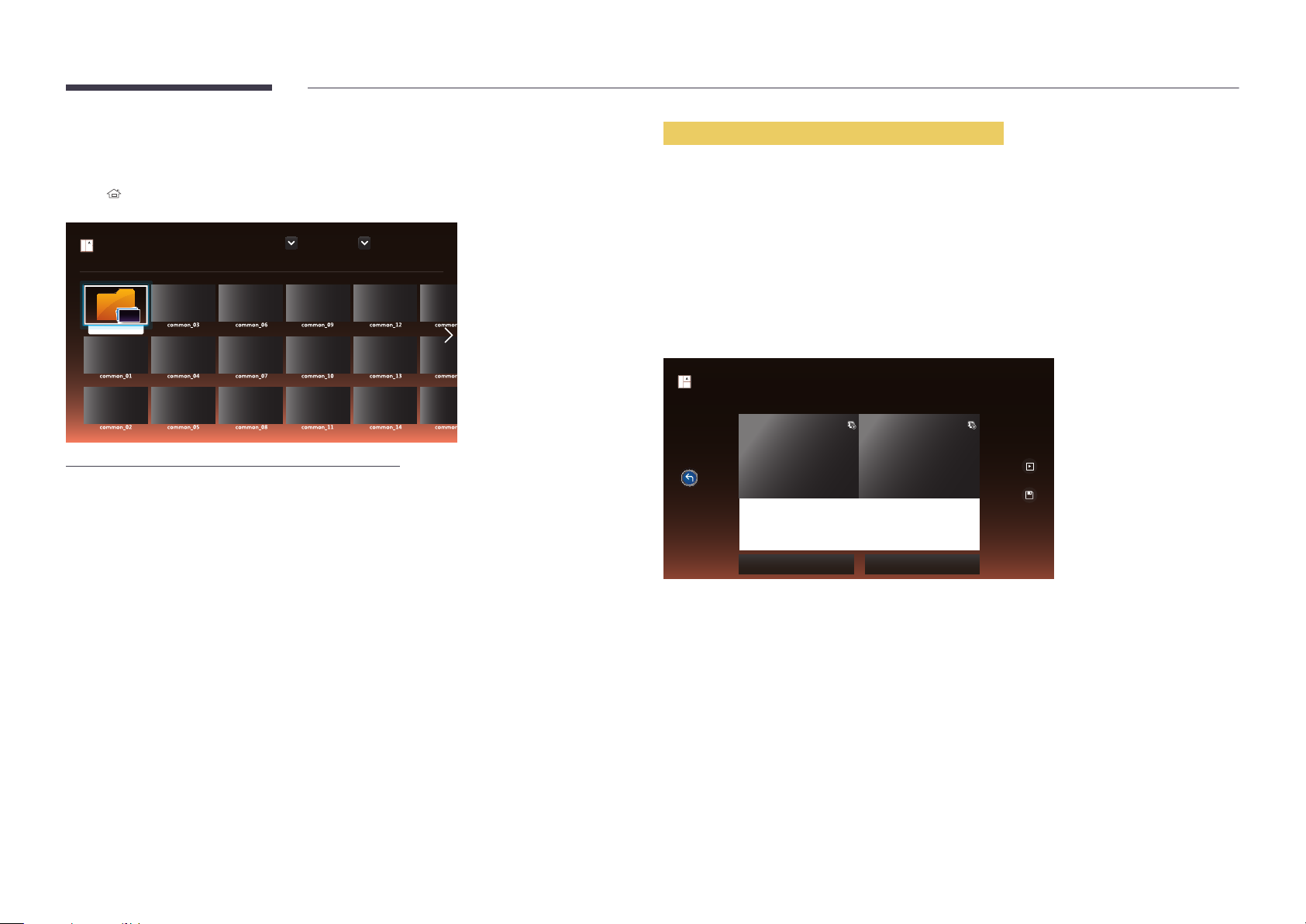
Template
HOME → Template → ENTER E
Template
Select a template to customise.
My Templates
Market : All
Orientation : Landscape
1 / 64 item(s)
Available features in the Template page
Create unique content using templates. It is easy to create content. Simply change images and text in a
template.
Sort the template list using the following criteria.
•
Market
•
Orientation
-
Landscape: Select this mode when using the product in landscape orientation.
-
Portrait: Select this mode when using the product in portrait orientation.
Select a template from the provided sample templates.
1
Create Template
Select in the editable zone to add content or edit the existing text.
-
The displayed image may differ depending on the model.
Cancel
New town
interior design
Sustainble evolution unfolods tomorrw’s design
Background Screen Background Music
Organize a template by inserting text, video, photo, or PDF files as desired.
2
bg_co...
Preview
Save
81
Page 82
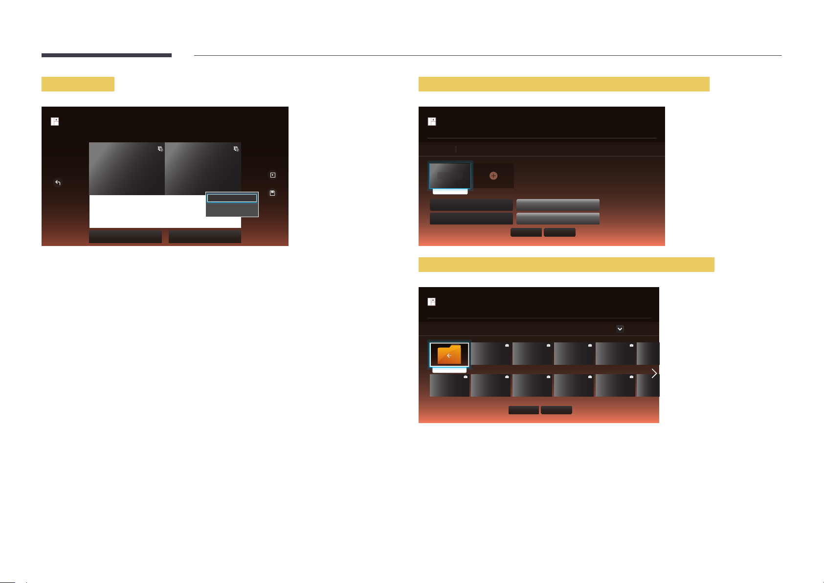
Entering text
Inserting content such as videos, photos and PDF files
Create Template
Select in the editable zone to add content or edit the existing text.
Cancel
New town
interior design
Sustainble evolution unfolods tomorrw’s design
Background Screen Background Music
bg_co...
Press the volume button on the remote to
Aa
change the font size.
Edit Text
Font options
Preview
Save
Edit Text
Select the Edit Text window to enter text.
Font options
Font Size: Specify the text size for the message.
Font Colour: Specify the text colour for the message.
Background colour: Specify the background colour for the message.
Background opacity: Specify the background transparency for the message.
Alignment: Select a message alignment mode.
Scroll: Specify the scroll direction/speed for the message.
Hide Element: Display or hide a message.
―
Selecting Hide does not reset the message settings.
Reset: Reset all settings in Font options to default settings.
Create Template
Select in the editable zone to add content or edit the existing text.
Edit
Item(s) selected
Select item to delete
picture1.jpg
Hide Element Show Aspect Ratio
Default content duration
00:00:05
Mute
Done Cancel
Configuring the background image/background music
Create Template
Select in the editable zone to add content or edit the existing text.
Background Screen
..
bg_common_02.jpg bg_common_04.jpg bg_common_06.jpg bg_common_10.jpg bg_commo
bg_common_03.jpgbg_common_01.jpg bg_common_05.jpg bg_common_07.jpg bg_common_11.jpg bg_commo
Done
Cancel
Device : All
82
Page 83
Preview
Configure Template Name and Storage.
3
Save
Template preview is running. It will stop after 20
seconds.
New town
interior design
Sustainble evolution unfolods tomorrw’s design
Preview the created template using the Preview feature.
1
To save the template, press the Save button.
2
Duration
Template Name
Storage
Save Cancel
Press the Save button to finish creating the content.
4
23:59:59
Template01
Internal
83
Page 84
Clone Product
Export settings on the product to an external storage device. You can also import settings from an external storage device.
This option is useful when assigning the same settings to several products.
HOME → Clone Product → ENTER E
Clone Product
-
The displayed image may differ depending on the model.
When a duplicate le is not found on the external storage device
Connect the external storage device, then run the Clone Product function.
1
The No cloning file found on the external storage device. Export this device's settings to the external storage
2
device? message appears.
When a duplicate le is found on the external storage device
Connect the external storage device, then run the Clone Product function.
1
The Cloning file found. Please select an option. message appears.
2
Run the Import from External Storage or Export to External Storage function.
-
Import from External Storage: Copy settings saved on an external storage device to the product.
-
Export to External Storage: Copy settings on the product to an external storage device.
―
After configuration is complete, the product is rebooted automatically.
84
Page 85
ID Settings
Assign an ID to a set.
HOME → ID Settings → ENTER E
ID Settings
-
The displayed image may differ depending on the model.
Device ID
Enter the ID number of the product connected to the input cable for input signal reception. (Range: 0~224)
―
Press u/d to select a number, and press E.
―
Enter the number you want using the number buttons on the remote control.
PC Connection Cable
Select a method to connect to MDC to receive the MDC signal.
•
RS232C cable
Communicate with MDC via the RS232C-stereo cable.
•
RJ-45 (LAN)/Wi-Fi Network
Communicate with MDC via the RJ45 cable.
Device ID Auto Set
This feature automatically allots an ID number to a device connected via an RS232C cable.
When multiple devices are connected, enable the feature on either the first or last device.
85
Page 86
Video Wall
HOME → Video Wall → ENTER E
Customize the layout of multiple displays that are connected to form a video wall.
In addition, display part of a whole picture or repeat the same picture on each of the connected multiple displays.
To display multiple images, refer to MDC Help or the MagicInfo user guide. Some models may not support the MagicInfo
function.
Video Wall
-
The displayed image may differ depending on the model.
Apply to
•
Current Source (screen output from a device connected to Source): Configure videowall features for the screen output
from an external device connected to the product.
•
MagicInfo Player S: Configure videowall features for content saved in the product or content saved on a USB memory or
SD card.
Restrictions
―
Playback may be initially choppy if video files of different resolutions play successively (i.e., 1280x720 content plays after
1920x1080 content) or an image file and a video file play one after the other.
Video Image
•
Supported resolution
-
1920 x 1080 @ 24p/30p
-
1280 x 720 @ 24p/30p/60p
•
HEVC and 3D images are not supported.
•
Compatible image file format: Jpeg, png, bmp
•
Supported maximum resolution
-
jpeg: 15360 x 8640
-
png: 4096 x 4096
-
bmp: 4096 x 4096
86
Page 87
Video Wall
You can activate or deactivate Video Wall.
To organize a video wall, select On.
•
Off / On
Horizontal x Vertical
This feature automatically splits a videowall display based on a videowall matrix configuration.
Enter the videowall matrix.
The videowall display is split based on the configured matrix. The number of vertical or horizontal display devices can be set within the range 1 and 15.
―
A videowall display can be split into a maximum of 100 screens.
―
The Horizontal x Vertical option is only enabled when Video Wall is set to On.
Screen Position
To rearrange split screens, adjust the number for each product in the matrix using the Screen Position feature.
Selecting Screen Position will display the videowall matrix with the numbers assigned to the products that form the videowall.
To rearrange products, use the direction buttons on the remote control to move a product to another desired number. Press the E button.
•
All Displays: Assign screen positions to All displays. Then, you don't need to set up video wall for individual displays.
•
Current Displays: Only Assign screen position for this first display.
―
Screen Position allows you to split the screen into a maximum of 100 views (15x15). The maximum number of views that can be split when products are connected via
DP Loopout is also 100.
―
The Screen Position option is only enabled when Video Wall is set to On.
―
To use the function, make sure Horizontal x Vertical is configured.
Format
Select how to display images on the videowall display.
•
Full: Display images in full screen with no margin.
•
Natural: Display images in the original aspect ratio without enlarging or reducing the size.
―
The Format option is only enabled when Video Wall is set to On.
87
Page 88
Network Status
HOME → Network Status → ENTER E
Network Status
-
The displayed image may differ depending on the model.
Check the current network and Internet connection.
88
Page 89
Picture Mode
HOME → Picture Mode → ENTER E
Picture Mode
-
The displayed image may differ depending on the model.
Select a picture mode (Picture Mode) suitable for the environment where the product will be used.
Videos/Images mode improves the picture quality of the video device. Tex t mode improves the picture quality of the
computer.
•
Shops & Malls
Suitable for shopping malls.
-
Select either Videos/Images or Tex t depending on the picture mode.
•
Offices & Schools
Suitable for offices and schools.
-
Select either Videos/Images or Tex t depending on the picture mode.
•
Terminals & Stations
Suitable for bus terminals and train stations.
-
Select either Videos/Images or Tex t depending on the picture mode.
•
Video Wall
Suitable for environments where videowall display are used.
-
Select either Videos/Images or Tex t depending on the picture mode.
•
Calibration
In this mode, the brightness, colour, gamma and uniformity settings customized using the colour calibration programme
Advanced Color Management are applied.
-
To apply the Calibration mode properly, make sure you configure the picture quality settings, such as brightness,
colour, gamma and uniformity, using the colour calibration programme Advanced Color Management.
-
To download the Advanced Color Management programme, visit www.samsung.com/displaysolutions.
•
BD Wise
Provides the optimal picture quality for Samsung DVD, Blu-ray and Home Theatre products which support BD Wise.
When BD Wise is turned On, the picture mode is automatically changed to the optimal resolution.
-
Available when you connect Samsung products that support BD Wise through an HDMI cable to the product.
-
The BD Wise function is enabled only when a source device with the BD Wise function is connected.
89
Page 90
On/O Timer
―
You must set Clock Set before you can use this feature.
HOME → On/Off Timer → ENTER E
On/Off Timer
-
The displayed image may differ depending on the model.
On Timer
Set On Timer so that your product turns on automatically at a time and on a day of your choosing.
The power is turned on with the specified volume or input source.
On Timer: Set the on timer by making a selection from one of the seven options. Ensure you set the current time first.
(On Timer 1 ~ On Timer 7)
•
Setup: Select Off, Once, Everyday, Mon~Fri, Mon~Sat, Sat~Sun or Manual.
If you select Manual, you can choose the days you want On Timer to turn on your product.
-
The check mark indicates days you’ve selected.
•
Time: Set the hour and minute. Use the number buttons or the up and down arrow keys to enter numbers. Use the left
and right arrow buttons to change entry fields.
•
Volume: Set the desired volume level. Use the left and right arrow buttons to change the volume level.
•
Source: Select the input source of your choice.
•
Content (when the Source is set to Internal/USB): From the USB device or internal memory device, select a folder
containing content you want to play when the product turns on. Content can include music, photo or video files.
―
This function is available only when a USB device is connected.
―
If there is no music file on the USB device or you don’t select a folder containing a music file, the Timer function does not
operate correctly.
―
If there is only one photo file in the USB, the Slide Show will not play.
―
If a folder name is too long, the folder cannot be selected. Up to 255 characters are recognizable.
―
Each USB you use is assigned its own folder. When using more than one of the same type of USB, make sure the folders
assigned to each USB have different names.
―
We recommend that you use a USB memory stick and a multi card reader when using On Timer.
―
The On Timer function may not work with USB devices with a built-in battery, MP3 players, or PMPs made by some
manufacturers because the product can take too long to recognize these devices.
90
Page 91

O Timer
Set the off timer (Off Timer) by making a selection from one of the seven options. (Off Timer 1 ~ Off Timer 7)
•
Setup: Select Off, Once, Everyday, Mon~Fri, Mon~Sat, Sat~Sun or Manual.
If you select Manual, you can choose the days you want Off Timer to turn off your product.
-
The check mark indicates days you’ve selected.
•
Time: Set the hour and minute. Use the number buttons or the up and down arrow keys to enter numbers. Use the left
and right arrow buttons to change entry fields.
Holiday Management
Timer will be disabled during a period specified as a holiday.
•
Add Holiday: Specify the period you want to add as a holiday.
Select the start and end dates of the holiday you want to add using the u/d buttons, and click the Save button.
The period will be added to the list of holidays.
-
Start: Set the start date of the holiday.
-
End: Set the end date of the holiday.
―
Delete: Delete selected items from the list of holidays.
―
Edit: Select a holiday item and then change the date.
•
Set Applied Timer: Set the On Timer and Off Timer to not activate on public holidays.
-
Press E to select the On Timer and Off Timer settings you do not want to activate.
-
The selected On Timer and Off Timer will not activate.
91
Page 92
Ticker
HOME → Ticker → ENTER E
Ticker
-
The displayed image may differ depending on the model.
Input text while a video or image is displayed and display the text on the screen.
•
Off / On
•
Message: Enter a message to display on the screen.
•
Time: Set the Start Time and End Time to display a Message.
•
Font options: Specify the text font and colour for the message.
•
Position: Select an orientation to display a Message.
•
Scroll: Specify the scroll Direction and Speed for the message.
•
Preview: Preview configured caption settings.
More settings
HOME → More settings → ENTER E
More settings
-
The displayed image may differ depending on the model.
The picture settings menu appears.
92
Page 93
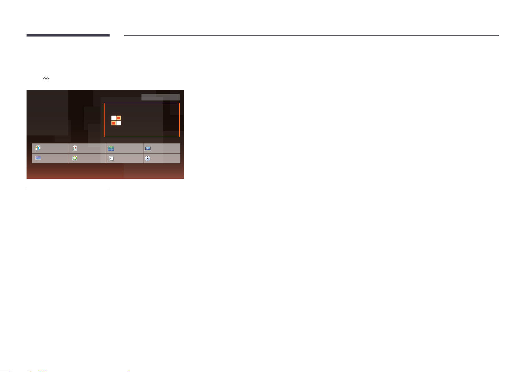
URL Launcher
HOME → URL Launcher → ENTER E
pm
12:00
January 1 2015
Change URL
URL Launcher
For details on how to use the URL Launcher feature, contact the dealer the product was purchased from.
―
To use the URL Launcher feature, set Play via to URL Launcher in System.
Clone Product
Picture Mode
-
The displayed image may differ depending on the model.
ID Settings
On/Off Timer
Video Wall
Ticker
Network Status
More settings
93
Page 94
Chapter 06
Screen Adjustment
Configure the Picture settings (Backlight, Colour Tone, etc.).
The layout of the Picture menu options may vary depending on the product.
Picture Mode
MENU m → Picture → Picture Mode → ENTER E
Picture
Picture Mode
·
Backlight
·
Contrast
·
Brightness
·
Sharpness
·
Colour
·
Tint (G/R)
-
The displayed image may differ depending on the model.
Shops & Malls
G50 R50
80
70
45
50
50
Select a picture mode (Picture Mode) suitable for the environment where the product will be used.
Videos/Images mode improves the picture quality of the video device. Tex t mode improves the picture quality of the
computer.
•
Shops & Malls
Suitable for shopping malls.
-
Select either Videos/Images or Tex t depending on the picture mode.
•
Offices & Schools
Suitable for offices and schools.
-
Select either Videos/Images or Tex t depending on the picture mode.
•
Terminals & Stations
Suitable for bus terminals and train stations.
-
Select either Videos/Images or Tex t depending on the picture mode.
•
Video Wall
Suitable for environments where videowall display are used.
-
Select either Videos/Images or Tex t depending on the picture mode.
•
Calibration
In this mode, the brightness, colour, gamma and uniformity settings customized using the colour calibration programme
Advanced Colour Management are applied.
-
To apply the Calibration mode properly, make sure you configure the picture quality settings, such as brightness,
colour, gamma and uniformity, using the colour calibration programme Advanced Colour Management.
-
To download the Advanced Colour Management programme, visit www.samsung.com/displaysolutions.
•
BD Wise
Provides the optimal picture quality for Samsung DVD, Blu-ray and Home Theatre products which support BD Wise.
When BD Wise is turned On, the picture mode is automatically changed to the optimal resolution.
-
Available when you connect Samsung products that support BD Wise through an HDMI cable to the product.
-
The BD Wise function is enabled only when a source device with the BD Wise function is connected.
94
Page 95
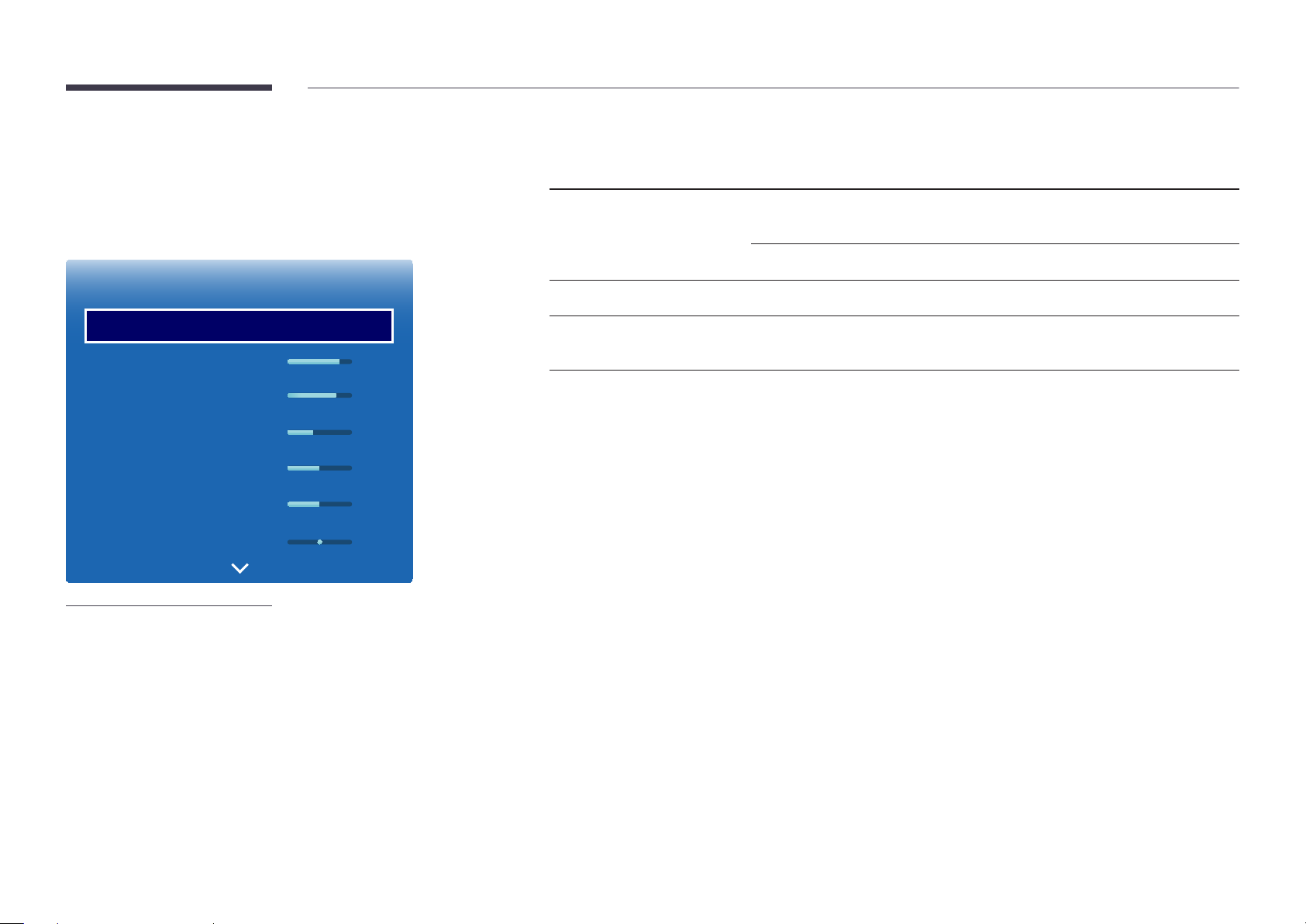
Backlight / Contrast / Brightness /
Sharpness / Colour / Tint (G/R)
MENU m → Picture → ENTER E
Your product has several options for adjusting picture quality.
Picture Mode Picture Mode settings Adjustable options
Shops & Malls, Offices & Schools,
Terminals & Stations, Video Wall
Videos/Images Backlight / Contrast / Brightness / Sharpness /
Colour / Tint (G/R)
Tex t Backlight / Contrast / Brightness / Sharpness
Picture
Picture Mode
·
Backlight
·
Contrast
·
Brightness
·
Sharpness
·
Colour
·
Tint (G/R)
-
The displayed image may differ depending on the model.
Shops & Malls
G50 R50
80
70
45
50
50
Calibration Backlight
BD Wise Backlight / Contrast / Brightness / Sharpness /
Colour / Tint (G/R)
―
When you make changes to Backlight, Contrast, Brightness, Sharpness, Colour or Tint (G/R), the OSD will be adjusted
accordingly.
―
You can adjust and store settings for each external device you have connected to an input on the product.
―
Lowering picture brightness reduces power consumption.
95
Page 96
Colour Temperature
MENU m → Picture → Colour Temperature → ENTER E
Picture
Colour Temperature 16000K
-
The displayed image may differ depending on the model.
Adjust the colour temperature (Red / Green / Blue). (Range: 2800K–16000K)
―
Enabled when Colour Tone is set to Off.
―
Colour Temperature is disabled if Picture Mode is set to Calibration or BD Wise.
96
Page 97
White Balance
MENU m → Picture → White Balance → ENTER E
Picture
2 Point
Adjust the colour temperature for a more natural picture.
•
R-Offset / G-Offset / B-Offset: Adjust each colour’s (red, green, blue) darkness.
•
R-Gain / G-Gain / B-Gain: Adjust each colour’s (red, green, blue) brightness.
•
Reset: Suitable for environments where videowall display are used.
White Balance
-
The displayed image may differ depending on the model.
10 Point
Controls the white balance in 10 point interval by adjusting the red, green, and blue brightness.
•
10 Point (Off / On)
―
Level, Red, Green, Blue and Reset are enabled only when 10 Point is set to On.
•
Level: Select interval to adjust.
•
Red: Adjust the red level.
•
Green: Adjust the green level.
•
Blue: Adjust the blue level.
•
Reset: Suitable for environments where videowall display are used.
―
Some external devices may not support this function.
―
Enabled when Picture Mode is set to Offices & Schools (Videos/Images).
97
Page 98
Gamma
MENU m → Picture → Gamma → ENTER E
Picture
Gamma 0
-
The displayed image may differ depending on the model.
Adjust the primary colour intensity.
―
If Picture Mode is set to Calibration, Gamma is disabled.
Calibrated value
MENU m → Picture → Calibrated value → ENTER E
Picture
Calibrated value
-
The displayed image may differ depending on the model.
Don't apply
Select whether to apply the brightness, colour, gamma and uniformity settings customized using the colour calibration
programme Advanced Colour Management to the Information and Advertisement modes.
•
Don't apply / Apply
―
To download the Advanced Colour Management programme, visit www.samsung.com/displaysolutions.
―
If Picture Mode is set to Calibration, Calibrated value is disabled.
98
Page 99
Advanced Settings
MENU m → Picture → Advanced Settings → ENTER E
Picture Mode Picture Mode settings Adjustable options
Shops & Malls, Offices & Schools,
Video Wall
Videos/Images
Dynamic Contrast / Black Tone / Flesh Tone /
RGB Only Mode / Colour Space
Advanced Settings
Dynamic Contrast
Black Tone
Flesh Tone
RGB Only Mode
Colour Space
Motion Lighting
-
The displayed image may differ depending on the model.
O
O
O
Native
O
Tex t
Terminals & Stations Videos/Images
Tex t
0
BD Wise
―
If Picture Mode is set to Calibration, Advanced Settings is disabled.
Dynamic Contrast / Black Tone
Dynamic Contrast / Black Tone / Flesh Tone
/ RGB Only Mode / Colour Space / Motion
Lighting
Dynamic Contrast / Black Tone
Dynamic Contrast / Black Tone / Flesh Tone /
RGB Only Mode / Colour Space
99
Page 100
Advanced Settings
Dynamic Contrast
O
Dynamic Contrast
Adjust the screen contrast.
•
Off / Low / Medium / High
Black Tone
Flesh Tone
RGB Only Mode
Colour Space
Motion Lighting
-
The displayed image may differ depending on the model.
O
O
Native
O
0
Select the black level to adjust the screen depth.
•
Off / Dark / Darker / Darkest
Flesh Tone
Black Tone
Emphasize pink Flesh Tone.
RGB Only Mode
Displays the Red, Green and Blue colour for making fine adjustments to the hue and saturation.
•
Off / Red / Green / Blue
Colour Space
Adjusts the range and variety of colours (the colour space) available to create images.
•
Auto / Native / Custom
―
To adjust Colour, Red, Green, Blue and Reset, set Colour Space to Custom.
Motion Lighting
Reduces power consumption by reducing screen brightness when the picture on the screen is in motion.
―
Enabled when Picture Mode is set to Videos/Images.
•
Off / On
100
 Loading...