

Page 1
Disassembly & Reassembly
Samsung Electronics 12-1
12. Disassembly & Reassembly
12-1 Overhaul Disassembly & Reassembly
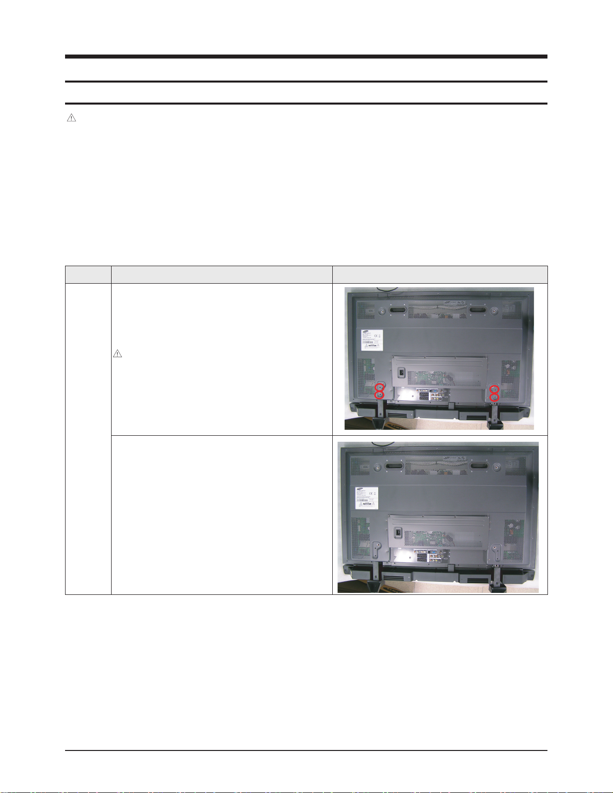
12-1-1 Separation of Stand
Caution
- Be sure to separate the power cord before disassembling the unit.
- Discharge the capacitors first when separating PCB's with high capacity capacitors such as SMPS, X Drive Board, Y Drive
Board, etc. (Sparks may be generated by an electric charge, and there is a danger of electronic shock.)
- Check that the cables are properly connected referring to the circuit diagram, when disassembling or assembling the unit and
take care not to damage the cables.
- Take care not to damage the Glass Filter at the front.
- Assemble the boards in the reverse order of the disassembly.
Part Name Description Description Photo
Stand
① Place the unit down and remove the 4 screws to
separate the stand.
: BH,+,S,M4,L35,ZPC(BLK)
6009-001432
Caution: Take care not to damage the front glass
when placing the unit down.
② Loosen and remove the screws and Stand remove.
Page 2
Disassembly & Reassembly
12-2 Samsung Electronics
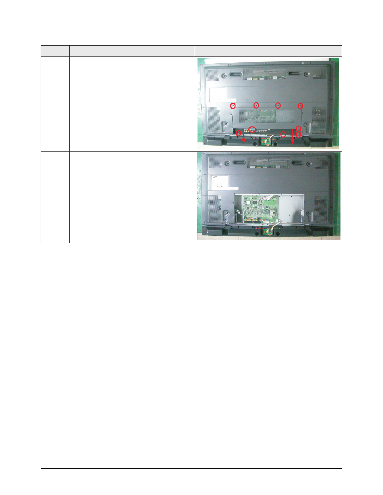
12-1-2 Separation of Sub Cover Back
Part Name Description Description Photo
Sub Cover
Back
① Remove all marked screws
② Loosen and remove the screws and Cable
Holder remove.
Page 3
Disassembly & Reassembly
Samsung Electronics 12-3
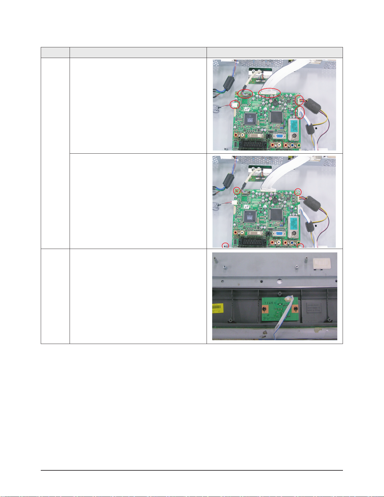
12-1-3 Separation of Main Board
Part Name Description Description Photo
Audio
Board
① Separate the cables connected to the Main Board
remove
② Loosen and remove the 4 screws.
③ Separation of Power Button, IR Receiver PCB.
Page 4
Disassembly & Reassembly
12-4 Samsung Electronics
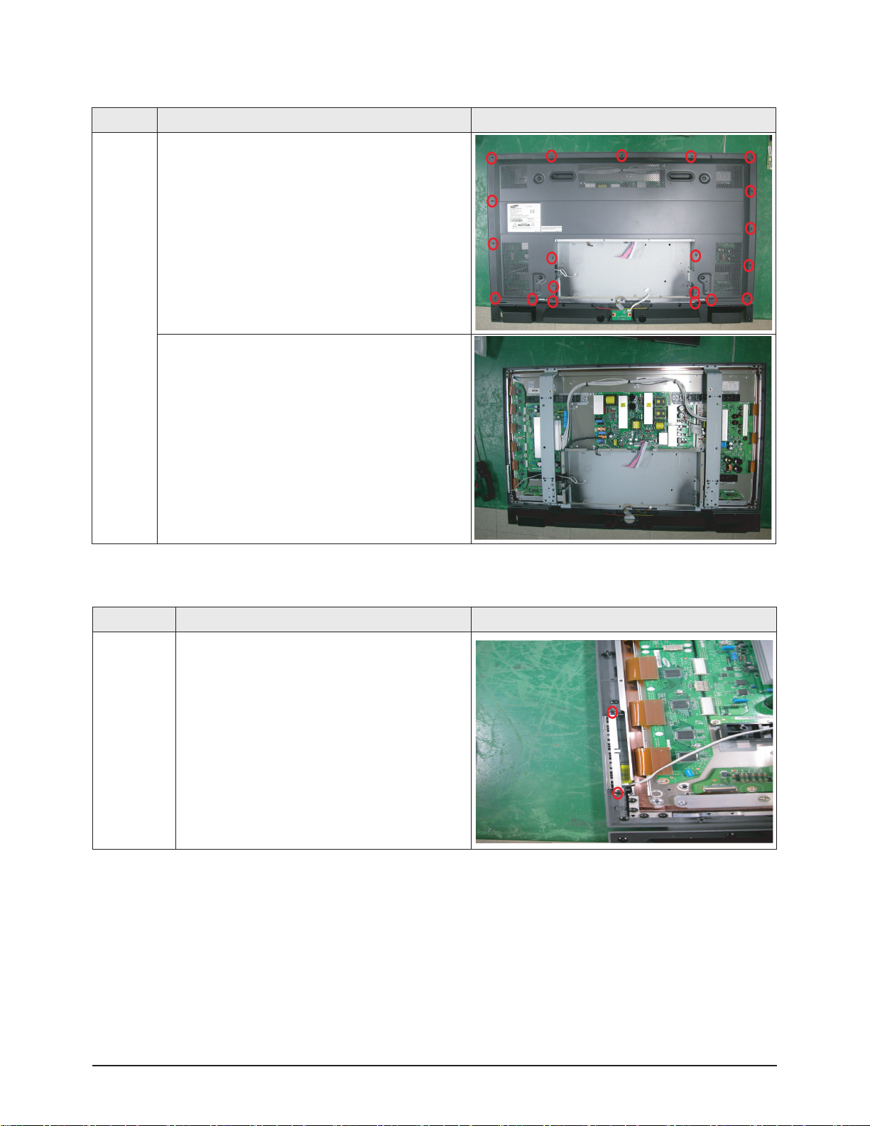
12-1-4 Separation of Back Cover
Part Name Description Description Photo
Back
Cover
① Remove all marked screws
② Take care not to damage the back cover when
removing it.
12-1-5 Separation of Function Key
Part Name Description Description Photo
Function Key
① Remove all marked screws
Page 5
Disassembly & Reassembly
Samsung Electronics 12-5
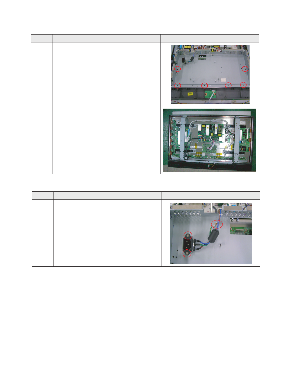
12-1-6 Separation of Audio Board Sub Back
Part Name Description Description Photo
Audio
Board Sub
Back
①Remove all marked screws
②Remove the Sub Back.
12-1-7 Separation of Power Inlet socket
Part Name Description Description Photo
Power Inlet
socket
① Loosen and remove the 3 screws.
Page 6
Disassembly & Reassembly
12-6 Samsung Electronics
Part Name Description Description Photo
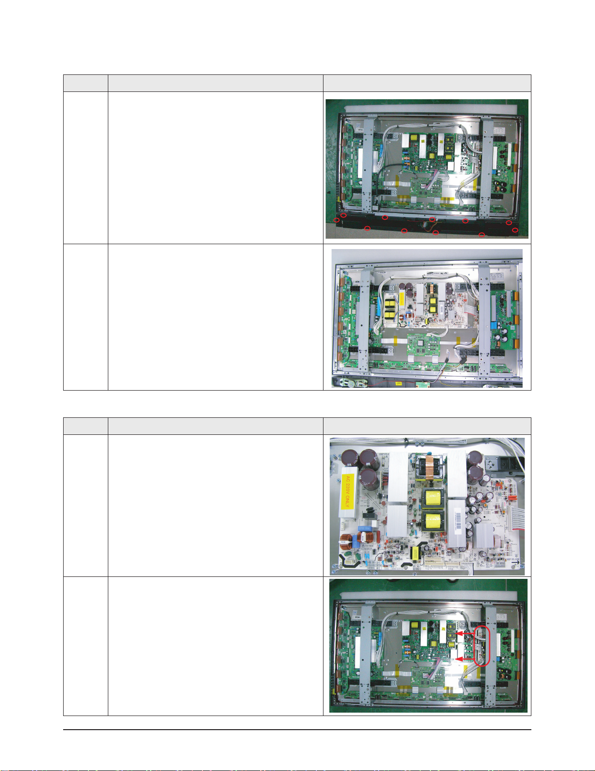
Speaker
① Remove all marked screws.
② Remove the speaker by carefully pulling it out with your
hands the speaker may cause damage to it.
12-1-8 Separation of Speaker
Part Name Description Description Photo
① Separate the cables connected to the Main SMPS first
and then remove the screws.
② Separate the cables connected to the DC-DC SMPS
and then remove the screws.
12-1-9 Separation of Main SMPS, DC-DC SMPS
Page 7
Disassembly & Reassembly
Samsung Electronics 12-7
Part Name Description Description Photo
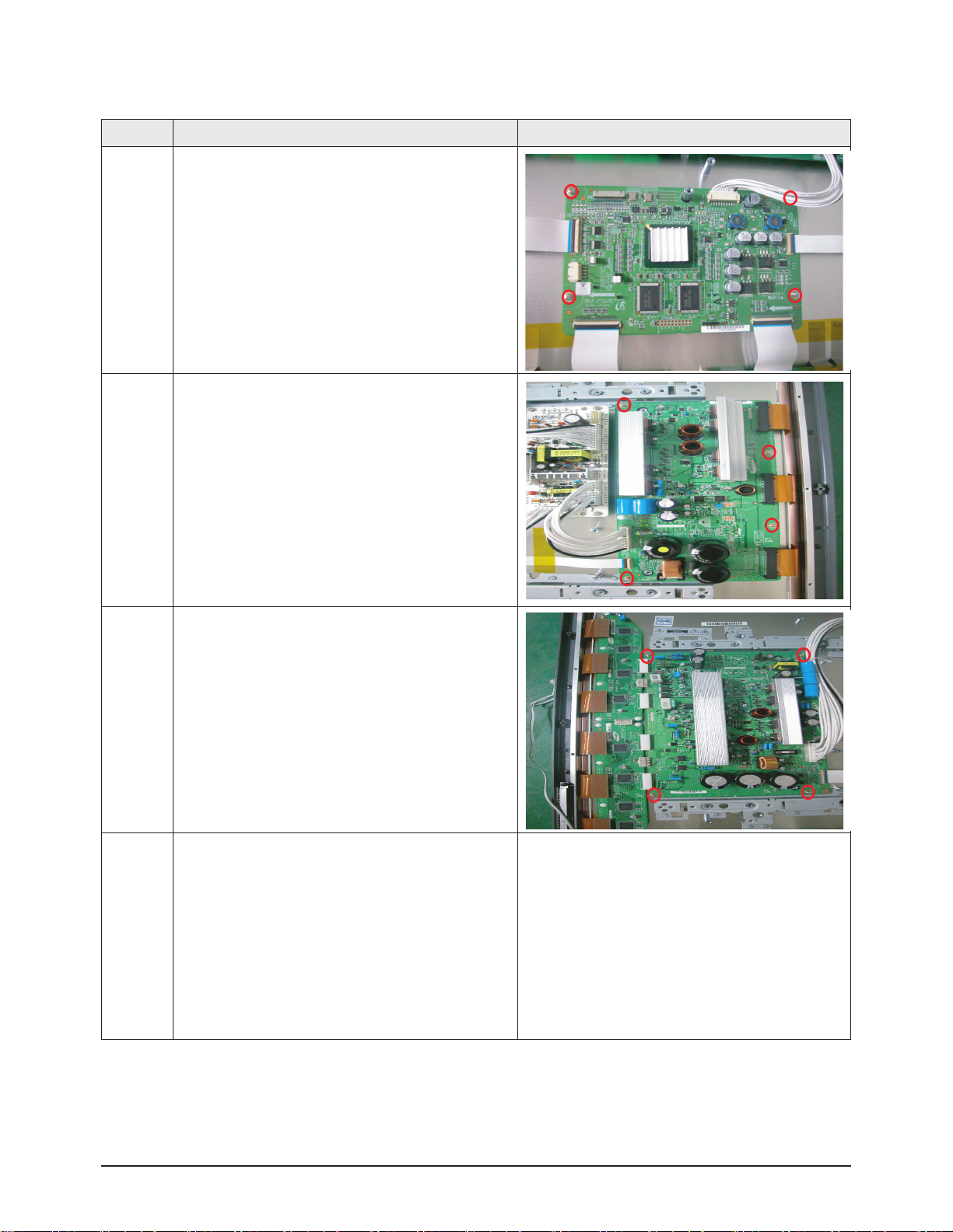
Board
① Separate the cables connected to the Logic Board and
then remove the screws.
② Separate the cables connected to the X Drive Board
and remove the screws.
③Separate the cables connected to the Y Drive Board
and remove the screws.
④Separate the Y Buffer Board and the Address Buffer
Board depending on the problem
12-1-10 Separation of LogicBoard, X DriveBoard, Y Drive Board, Buffer Board , Address Buffer Board
Page 8

12-8 Samsung Electronics
MEMO
 Loading...