

Page 1

19
3. DISASSEMBLY AND REASSEMBLY
3-1) CAUTION ON DISASSEMBLY ····················································································································································20
3-2) FREEZER DOOR
···············································································································································································21
3-3) REFRIGERATOR DOOR
································································································································································22
3-4) CONTROL PANEL
············································································································································································22
3-5) DOOR GASKET
·················································································································································································23
3-6) DOOR HANDLE
·················································································································································································23
3-7) TEMPERED GLASS SHELF
························································································································································23
3-8) PLASTIC DRAWERS IN REFRIGERATOR
·························································································································24
3-9) GALLON DOOR BIN
·······································································································································································24
3-10) WATTER FILTER
·············································································································································································24
3-11) EVAPORATOR COVER IN THE REFRIGERATOR
········································································································25
3-12) DOOR BIN IN FREEZER
····························································································································································26
3-13) PLASTIC (WIRE DRAWER IN FREEZER)
·························································································································27
3-14) FREEZER SHELF
···········································································································································································27
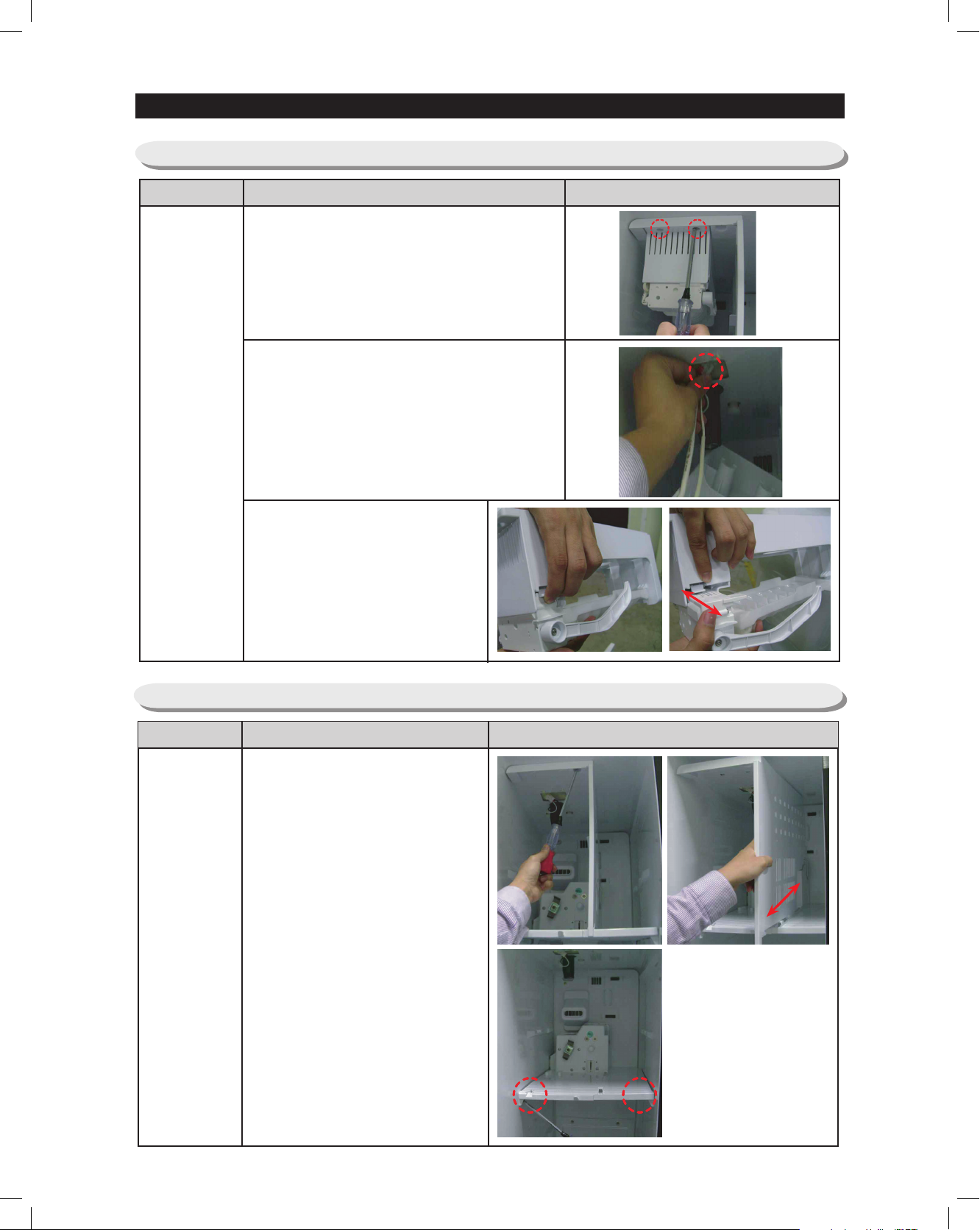
3-15) ICE DISPENSER & ICE MAKER
············································································································································27
3-16) ICE MAKER KIT
············································································································································································· 28
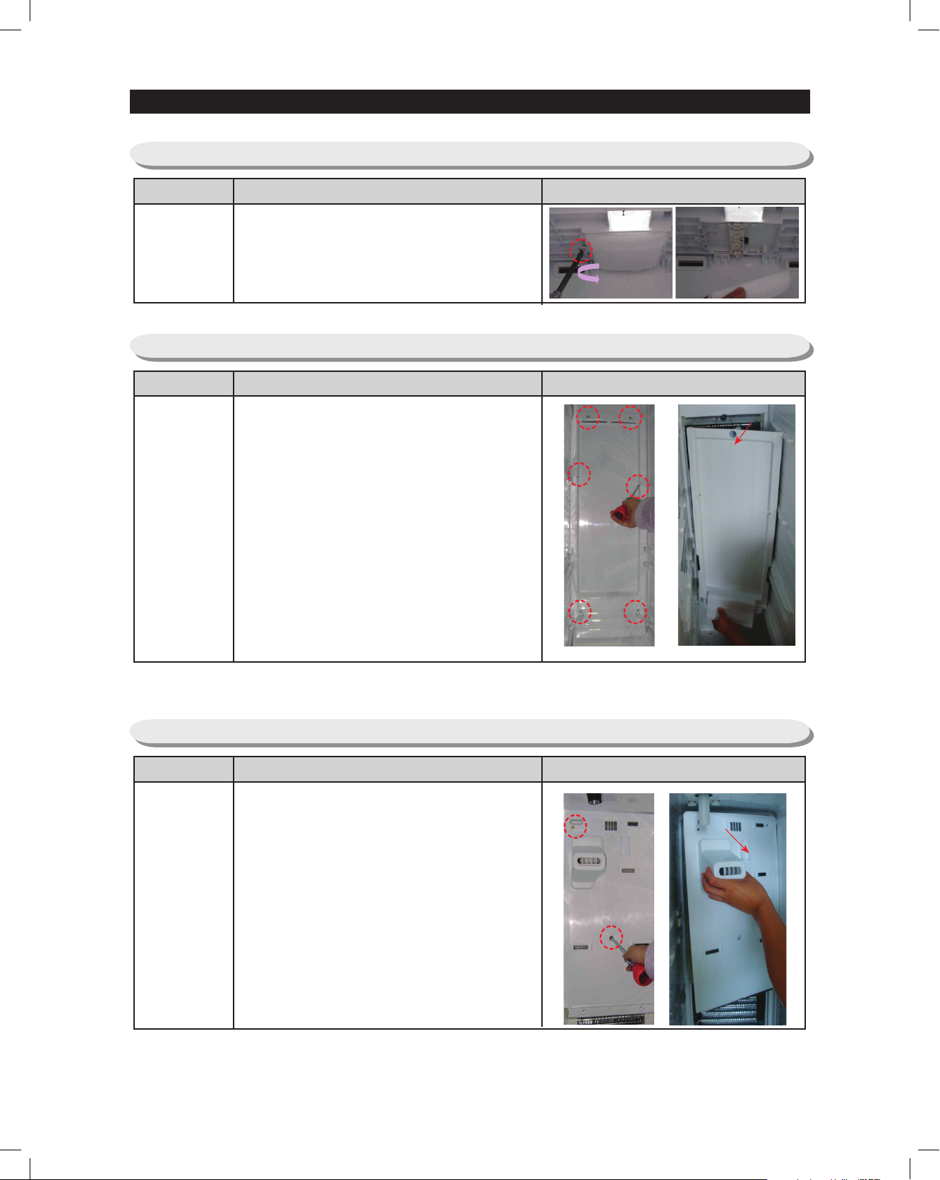
3-17) AUGER MOTOR CASE
·······························································································································································28
3-18) FREEZER LIGHTING
···································································································································································29
3-19) EVAPORATOR COVER IN FREEZER
··································································································································29
3-20) UPPER DUCT
··················································································································································································29
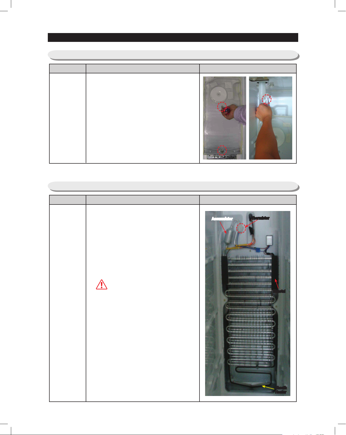
3-21) EVAPORATOR FAN MOTOR IN FREEZER
······················································································································30
3-22) EVAPORATOR IN FREEZER
····················································································································································30
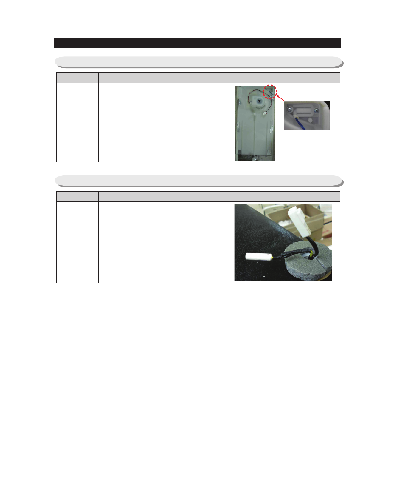
3-23) FREEZER THERMISTOR
···························································································································································31
3-24) AMBIENT THERMISTOR
···························································································································································31
3-25) MACHINE COMPARTMENT
····················································································································································32
Page 2
3. DISASSEMBLY AND REASSEMBLY
3-1) CAUTION ON DISASSEMBLY
●
When replacing or repairing electric components, unplug the power cord before you replace or repair.
→ Be careful of electric shock
●
When replacing electric components, use a regular component.
→ Be sure to check the indications like the model number, rating voltage, rating current, operation
temperature etc..
●
When repairing, the wiring of harness should be free from water infiltration and firm.
→ When applying force, the harness shouldn’t be detached.
●
When repairing, completely remove dust and foreign substances from housing, wiring, joint etc..
→ Prevents fire due to tracking or short.
●
Check if water came into electric components.
→ If there is a sign of water infiltration, replace the component and take necessary action like
insulation tapping etc..
●
Check the assembly of the component after repairing.
→ Maintain the same status as that before repairing.
●
Check the using environment of the refrigerator.
→ If the installation is made unstably or the machine is installed in humid conditions or water,
change its location.
●
If grounding seems necessary, ground it.
→ If there is risk of short-circuit due to water or humid conditions, be sure to ground the product.
●
Do not plug several devices in one socket.
●
Check for breakage, press, scratch, deterioration etc. of power plug and power outlet
→ Immediately repair if the power plug or power consent is defective.
→ When moving the product, be careful not to get scratch or pressed due to surrounding objects.
●
Do not store food unstably or do not store bottles in the freezer.
●
Do not let consumer repair the machine personally.
●
Do not store other materials except food in the refrigerator.
→ Medicine, chemical sample and etc. : Home refrigerator cannot maintain precise temperature.
→ Highly flammable material (alcohol, benzene, ether, LP gas, butane gas etc.) : explosive.
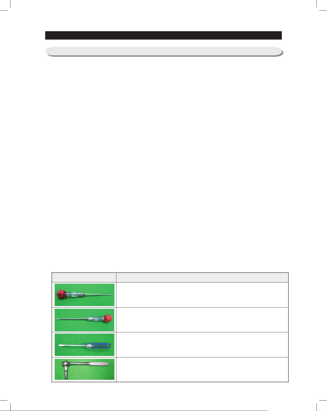
- TOOLS REQUIRED FOR DISASSEMBLY
IMAGE
ITEM
(+) SCREW DRIVER
(-) SCREW DRIVER
(-) SMALL SCREW DRIVER
SOCKET WRENCH (10 mm)
20
Page 3
3. DISASSEMBLY AND REASSEMBLY
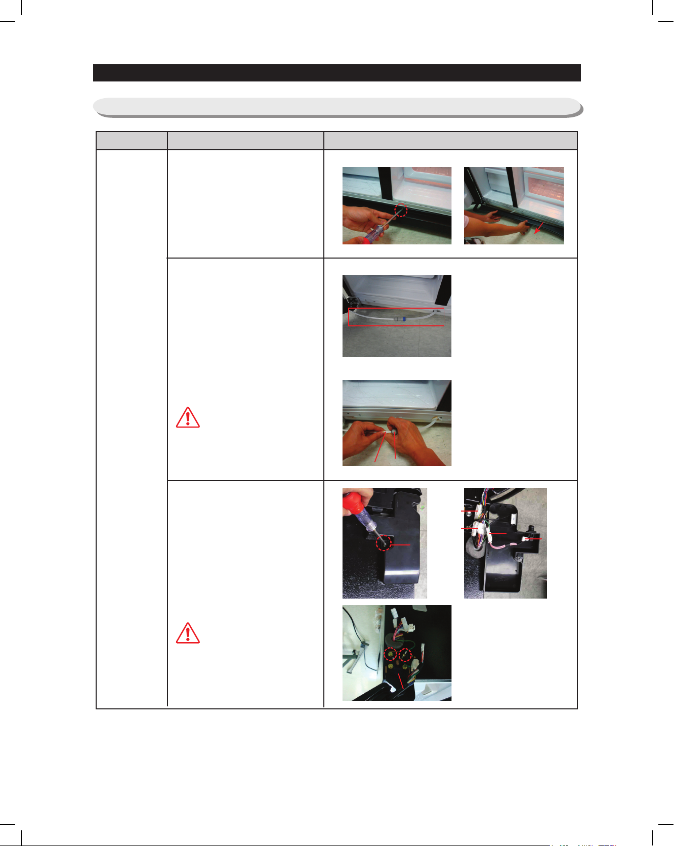
3-2) Freezer Door
Part name
Door
Freezer
How To Do
Removing the Front leg cover.
1. Open the freezer and
refrigerator doors.
2. Take off the front leg cover by
turning the three screw counterclockwise.
Removing the Water supply
line.
1. Separate the Water Supply Line
from the Refrigerator by
pressing the coupler(②)
2.pulling the water tube(①)away.
If a red clip is on the coupler,
it must be removed before
Caution
removing the tube.
Descriptive Picture
Removing the Upper hinge.
1. With the door colsed,remove
the upper hinge cover(
)using
①
a screwdriver.
2.Disconnect the wires(②).
3. Remove hinge screws(③)and
ground screw(④)counterclockwise and take off the
upper hinge(⑤)along the arrow.
When diassembling, make
sure the unit is turned off
Caution
①
③
②
⑤
①
④
②
②
②
②
21
Page 4
3-4) CONTROL PANEL
22
3. DISASSEMBLY AND REASSEMBLY
·Lift the door straight up.
·Be careful not to pinch the water tubing and wire harness on the door.
·Place doors on a protected surface.
·After disassembling the freezer / refrigerator door, move it to the appropriate location.
NOTE
3-3) REFRIGERATOR DOOR
Part name
Door Fre
How To Do
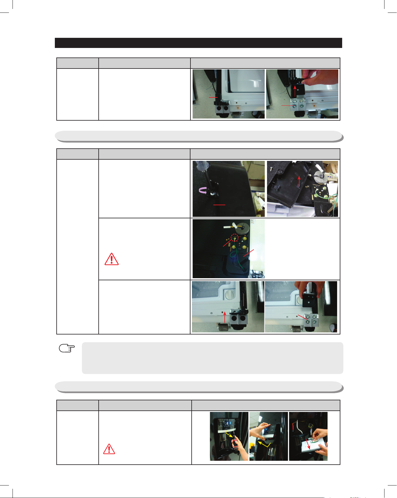
Removing the Lower hinge.
1. Remove the door from the lower
hinge(①)by carefully lifting the
door.
2. Remove the lower hinge from the
bracket hinge(②)by lifting the lower
hinge in the direction of the arrow.
Descriptive Picture
①
②
Part name
Control Panel
How To Do
1. Insert a (-)driver on the slot as
shown, and unlock the tabs.
2. Disconnect the wire connector in
the direction of the arrow.
Part name
Door Ref
Descriptive Picture
How To Do
Removing the Upper hinge.
1. With the door colsed,remove the
upper hinge cover(①)using a
screwdriver.
2.Remove hinge .
ground screw(②) and take off
the upper hinge(③)along the
arrow.
Removing the Lower hinge.
1. Remove the door from the lower
hinge(①)by carefully lifting the
door.
2. Remove the lower hinge from
the bracket hinge(②)by lifting
the lower hinge in the direction
of the arrow.
Descriptive Picture
①
③
②
①
②
Be careful not to scratch
Caution
When diassembling, make
sure the unit is turned off
Caution
Page 5
23
3. DISASSEMBLY AND REASSEMBLY
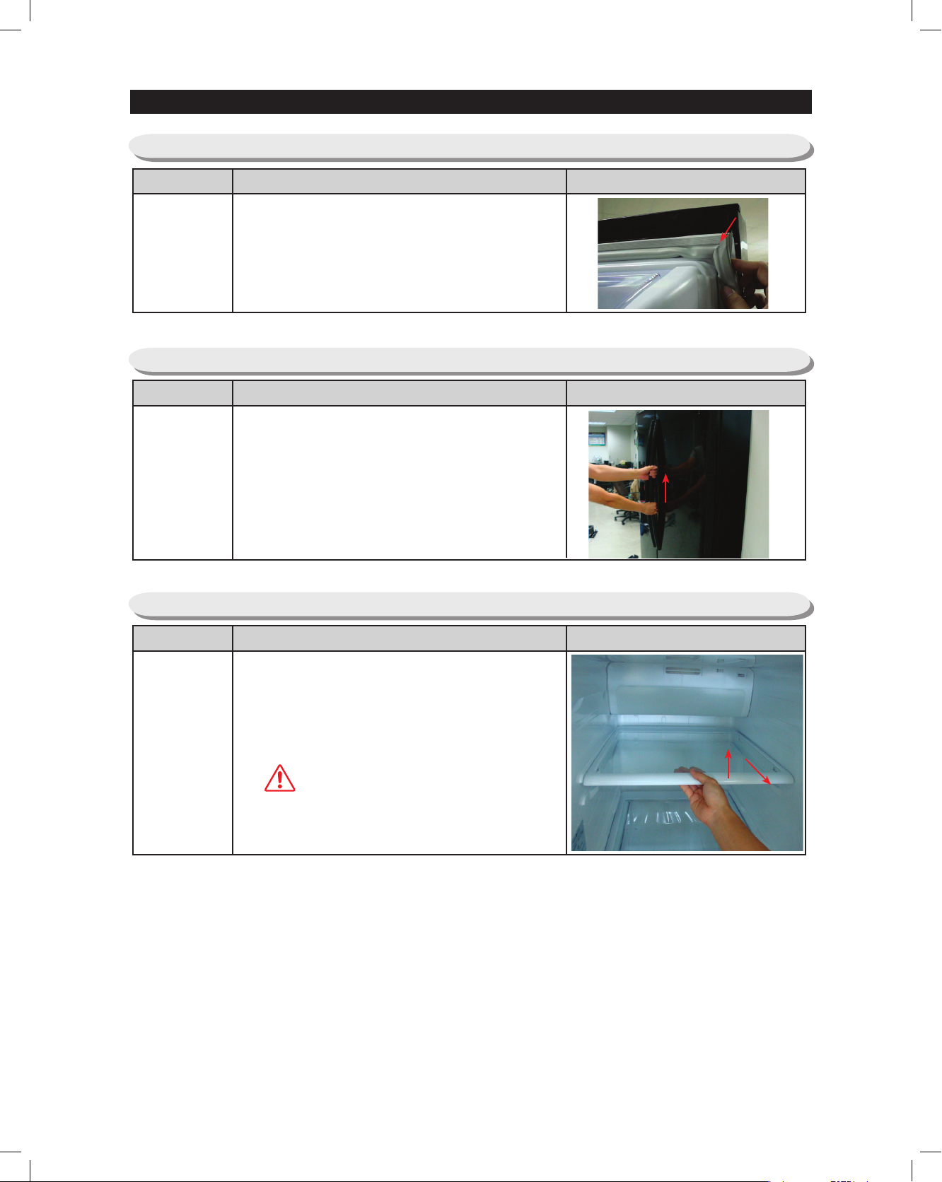
3-5) DOOR GASKET
Part name
Door Gasket
How To Do
Descriptive Picture
The door gasket is a molded gasket set into a
channel located in the door liner.
1.Open the door
2.
Grasp the gasket and pull in an outward motion until
the molded gasket separates from the door liner.
3-6) DOOR HANDLE
Part name
Door Handle
How To Do Descriptive Picture
Lift the handle upward motion with on.
Part name
Tempered
Glass Shelf
How To Do
These shelves allow storage of larger items and
pull out for easy access.
1. Pull the shelf out as far as it goes.
2. Lift it up and remove it.
3-7) TEMPERED GLASS SHELF
Descriptive Picture
Be careful of injury
Caution
Page 6
3. DISASSEMBLY AND REASSEMBLY
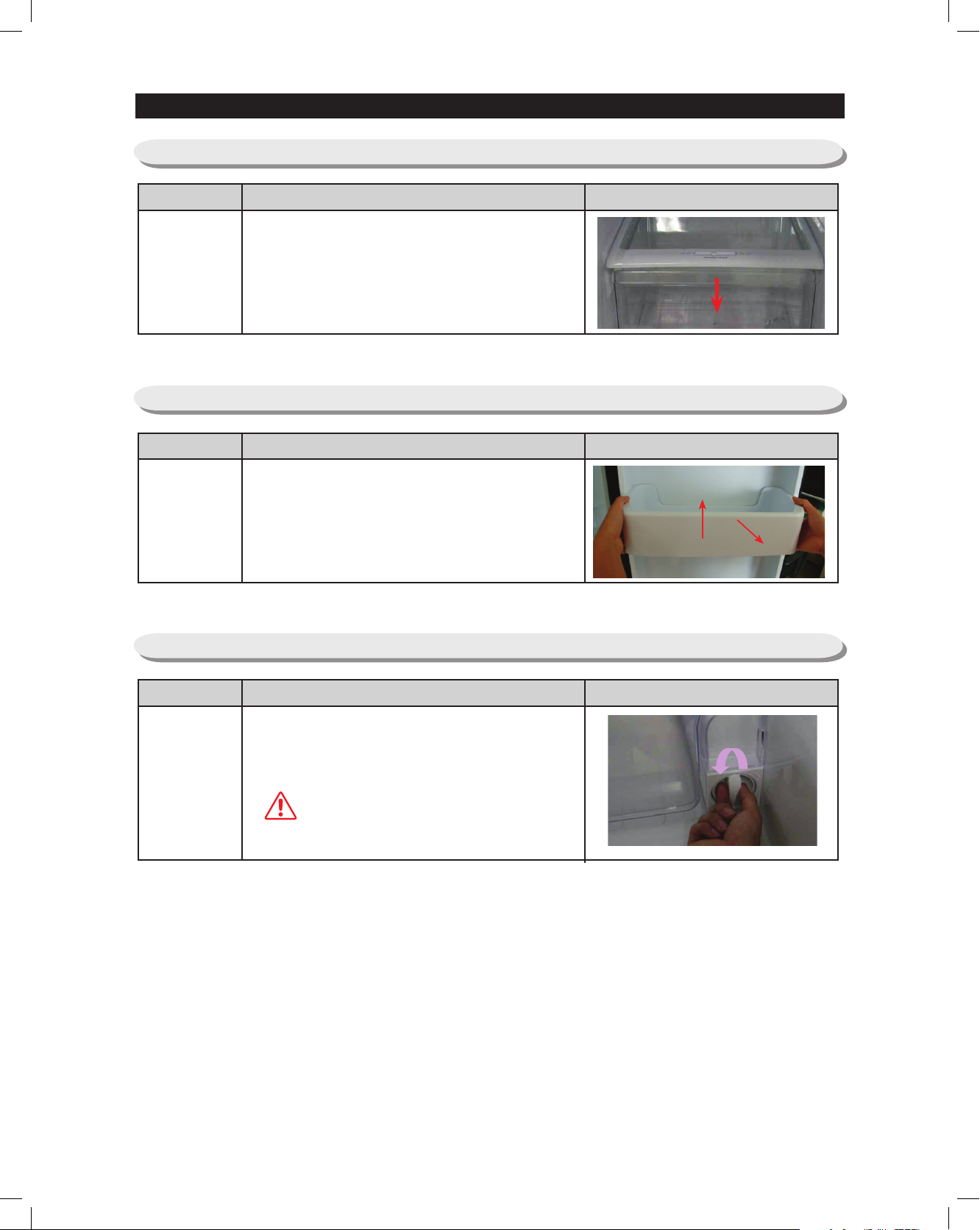
3-8) PLASTIC DRAWERS IN REFRIGERATOR
Part name
Drawers are designed for storage of fruits,
vegetables, and deli items, The drawers are
Drawer In
Refrigerator
located in the lower portion of the refrigerator.
1. Pull out the drawer as far as it goes.
2. Tilt the drawer up and pull it out until it is
removed.
3-9) GALLON DOOR BIN
Part name
The door bins allow storage of perishable items.
1. Push the bin up and slide it out.
Gallon Door Bin
How To Do
How To Do
Descriptive Picture
Descriptive Picture
3-10) WATER FILTER
Part name
Please replace the water lter located on the
bottom right by turning it in anti-clockwise
direction.
Water Filter
Caution
How To Do
Ensure to close the main water supply
before changing the water filter.
Descriptive Picture
24
Page 7
3. DISASSEMBLY AND REASSEMBLY
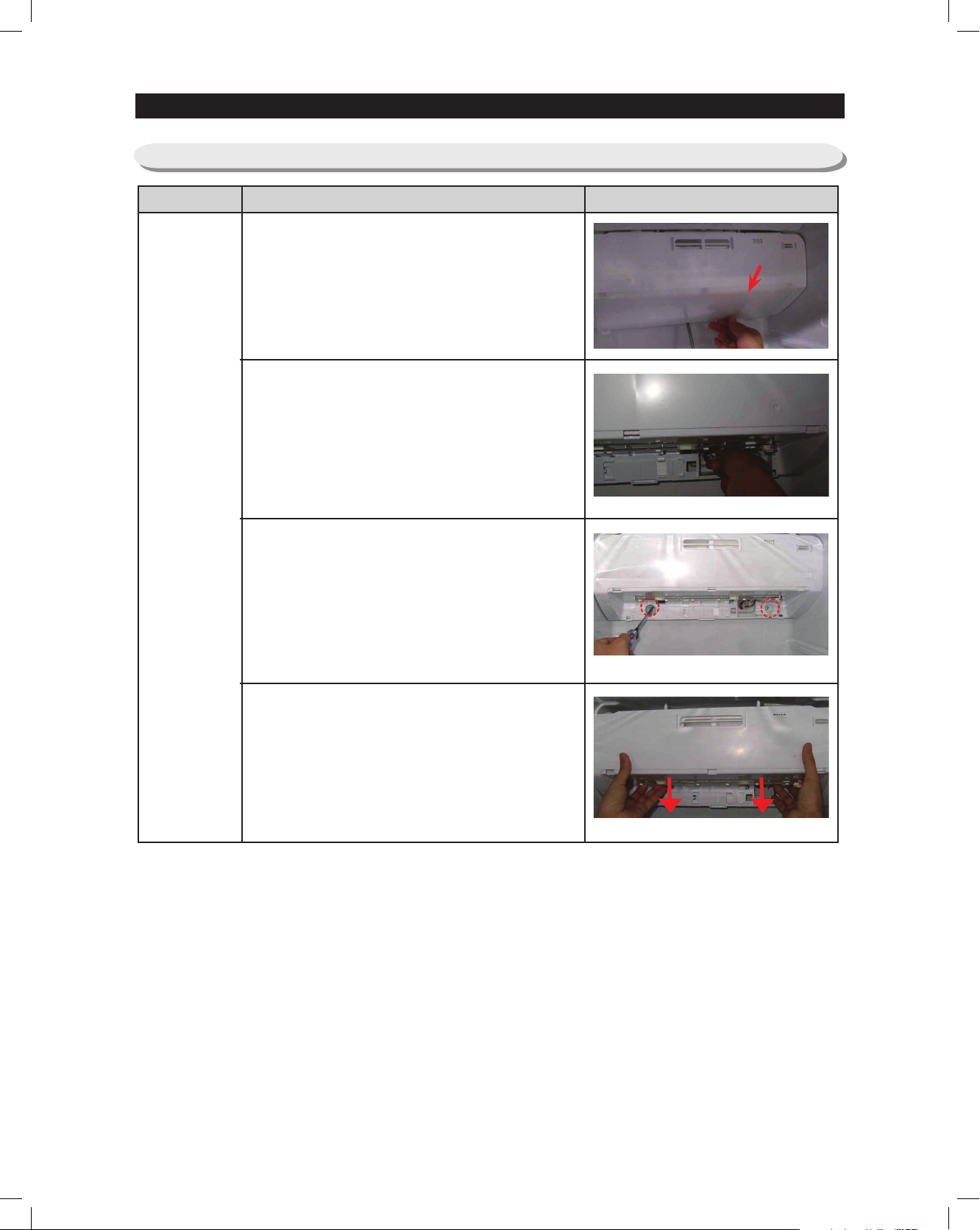
3-11) DAMPER COVER IN THE REFRIGERATOR
Part name
Descriptive PictureHow To Do
Pull out the screw cap and remove the screw.
Disconnect the wire connector.
Remove the screw.
Remove the cover damper in the direction of
arrow.
25
Page 8
26
3. DISASSEMBLY AND REASSEMBLY
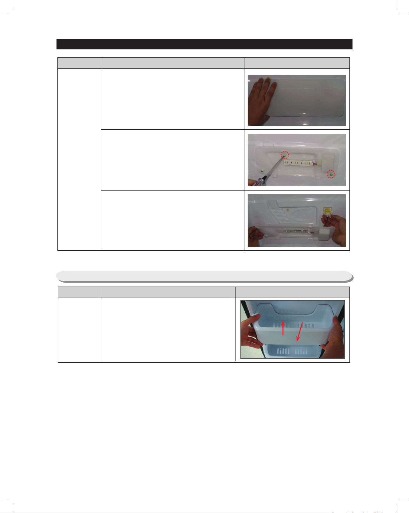
Part name
Evaporator
Cover
Descriptive PictureHow To Do
Part name
Door Bin In
Freezer
Descriptive PictureHow To Do
The door bins allow storage of perishable
items.
3-12) DOOR BIN IN FREEZER
Remove the cover housing.
Remove the screw.
Disconnect the wire connector.
Page 9
27
3. DISASSEMBLY AND REASSEMBLY
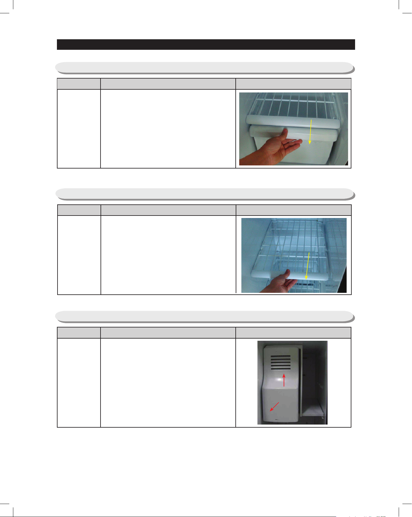
Part name
Drawer In
Freezer
Descriptive PictureHow To Do
Drawers are designed for storage of meat
and dry foods. The drawers are located in the
lower portion of the freezer.
1. Pull out the drawer as far as it goes.
2. Tilt the drawer up and pull it out until it is
removed.
3-13) PLASTIC (WIRE DRAWER IN FREEZER)
Part name
Freezer Shelf
Descriptive PictureDescriptive Picture
The shelves slide out for easy access for
frozen items.
1. Slide the shelf out as far as you can.
2. Tilt down and slide it out of the compartment.
3-14) FREEZER SHELF
Part name
Ice Dispenser &
Ice Maker
Descriptive PictureHow To Do
The ice dispenser is located in the upper
portion of the freezer. This assembly stores
ice made by the icemaker and dispenses ice.
1. Lift the ice bucket up ① and slide out the ice
dispenser assembly ②.
3-15) ICE DISPENSER & ICE MAKER
①
②
Page 10
28
3. DISASSEMBLY AND REASSEMBLY
Part name
Ice Maker Kit
Descriptive PictureHow To Do
1. Remove the screws.
2. Disconnect the ice maker wire connector.
3. Unlock the locking tabs to
separate the ice maker kit.
3-16) ICE MAKER KIT
Part name
Auger Motor
Case
Descriptive PictureHow To Do
This shelf is designed to
support the ice maker & ice
dispensed and Xtra SpaceTM.
1. Remove the Xtra Space
TM
cover (push it down and pull
front).
2. Slide the partition out.
3. Remove the screws (2) on
the bottom front of the case.
4. Slide out the case while
disconnecting the wire
connect.
3-17) AUGER MOTOR CASE
Page 11
29
3. DISASSEMBLY AND REASSEMBLY
Part name
Freezer
Lighting
Descriptive PictureHow To Do
The freezer Lighting is located in the bottom
of the auger motor case. The Lighting is
covered by an opaque cover.
1. Remove the screw and the Lighting cover.
3-18) FREEZER Lighting
Part name
Evaporator
Cover In
Freezer
Descriptive PictureHow To Do
1. Pull out the screw caps and remove
screws (6).
2. Remove the evaporator cover in the
direction of outwards.
3-19) EVAPORATOR COVER IN FREEZER
Part name
Upper Duct
Descriptive PictureDescriptive Picture
1. Remove the screws.
2. Remove the cover-evap front.
3-20 UPPER DUCT
Page 12
30
3. DISASSEMBLY AND REASSEMBLY
Part name
Evaporator
Fan motor
in freezer
Descriptive PictureHow To Do
The evaporator fan is located in the lower
rear of freezer. This fan circulates cold air in
the freezer.
1. Remove screws(4) located at the four corners
of the fan bracket.
2. Take the fan motor assembly off.
3-21) EVAPORATOR FAN MOTOR IN FREEZER
Part name
Evaporator In
Freezer
Descriptive PictureHow To Do
Evaporator is located in the bottom of freezer
to produce cold air driven across the
evaporator coils.
1. Take off the ductwork in Freezer.
2. Disconnect the wire connector (Heater,
Bimental, and Thermistor).
3. Desolder the inlet and outlet tubes.
4. Remove the evaporator.
5. Take the same steps to seal the system as
mentioned earlier.
3-22) EVAPORATOR IN FREEZER
When diassembling, make
sure the unit is turned off
Caution
Accumulator
Bimetal
Sheath
Heater
Thermistor
Page 13
31
3. DISASSEMBLY AND REASSEMBLY
Part name
Freezer
Thermistor
Descriptive PictureHow To Do
The freezer thermistor is located at the top
left of freezer vent. It sends temperature
signals to the micro-processor.
3-23) FREEZER THERMISTOR
Part name
Ambient
Thermistor
Descriptive PictureHow To Do
The ambient thermistor is located inside the
upper hinge cover.
The ambient thermistor sends temperature
signals to the micro-prosessor.
3-24) AMBIENT THERMISTOR
Page 14
3. DISASSEMBLY AND REASSEMBLY
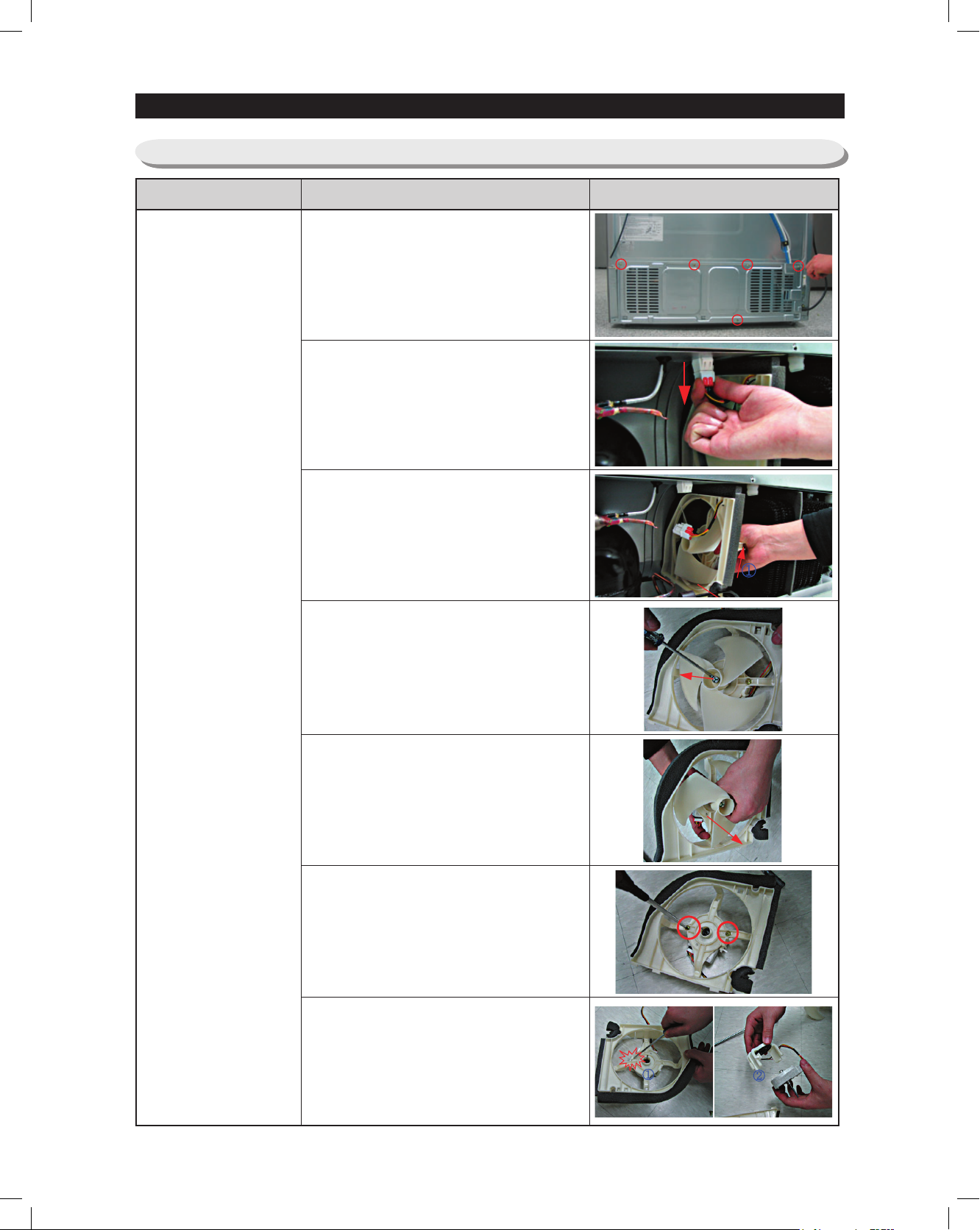
3-30) MAC HINE COMPARTMENT
3-25) MACHINE COMPARTMENT
Part name
How To Do
1. Unscrew 5 screws of cover
compressor.
2. Disengage the housing connector.
(Refer to the picture)
3. Remove the hook of support circuit
motor by lifting the hooker up and
pulling it out.
4. Remove the spring with a flatblade
screwdriver. (Refer to the picture)
Descriptive Picture
Motor Fan
5. Remove the motor fan by pulling the
fan out while grasping the motor part.
(Refer to the picture)
6. Unscrew 2 screws fixed in the motor.
7. Remove the hook of the motor cover
with a flat-blade (-) screwdriver and
then remove the motor.
32
Page 15
33
3. DISASSEMBLY AND REASSEMBLY
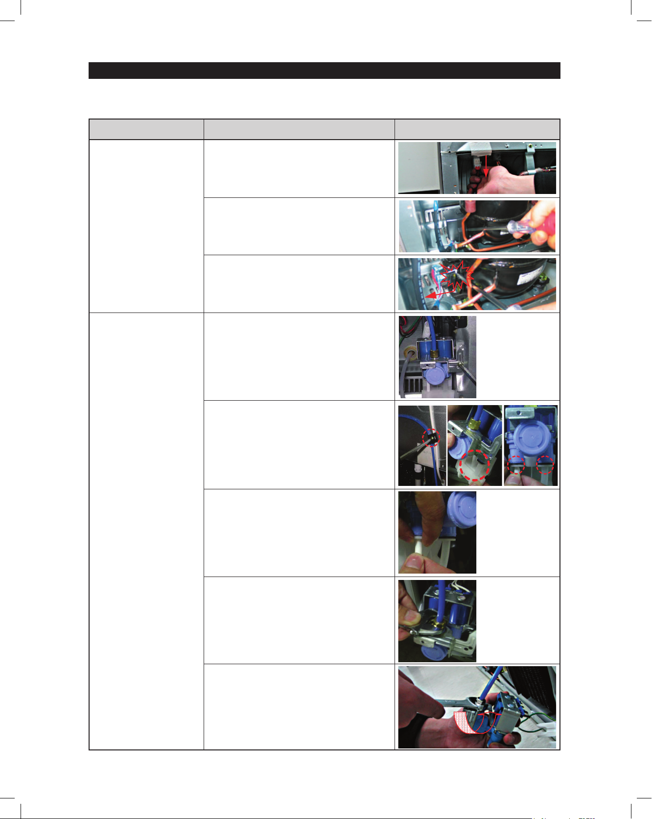
Part name
How To Do
Descriptive Picture
Relay O/L
Water Valve
1. Disengage the housing connector.
2.Remove Cover Relay.
3. Remove the relay O/L with a flat-blade
screwdriver. (Refer to the picture)
1. Unscrew the water valve fixed by the
screw.
2. Disassemble the white part.
Pull out the black pin.
3. Remove 2 water hose parts while
pushing the upper part of.
(Refer to the picture)
4. Disengage 2 housing connector parts.
5. Remove the hose connected by the
nut with a wrench(8mm).
 Loading...