

Page 1

2
CONTENTS
Ⅰ.SPECIFICATION
1.
SPECIFICATION
……………………………………………………………………………………………… 4
2.
SYSTEMREQUIREMENTS
…………………………………………………………………………………… 5
3.
LCDmonitorindicator
……………………………………………………………………………………… 6
4.
CONNECTIONDIAGRAM
…………………………………………………………………………………… 8
5.
IDENTIFICATIONOFFEATURES
…………………………………………………………………………… 9
Ⅱ.
INSTALLATION
……………………………………………………………………………………………… 11
Ⅲ.EXPLODEDVIEWANDPARTSLIST
1.MAINASSEMBLY ………………………………………………………………………………………………20
2.BODYASSEMBLY………………………………………………………………………………………………22
3.BODYASSEMBLY …………………………………………………………………………………………… 24
4.FRONTASSEMBLY ……………………………………………………………………………………………26
5.BACKCOVERASSEMBLY ……………………………………………………………………………………28
6.PACKINGITEM …………………………………………………………………………………………………30
Ⅳ.
ADJUSTMENT
1.DIGITALCAMERASERVICE……………………………………………………………………………………33
2.
HowtochecktheFIRMWAREVERSION
…………………………………………………………………39
3.
HowtoupgradeFIRMWARE
………………………………………………………………………………40
4.
ADJUSTMENT
…………………………………………………………………………………………………42
Ⅴ.PATTERNDIAGRAM
1.PARTSARRANGEMENTFOREACHPCBASS’Y
1)MAIN_TOP …………………………………………………………………………………………………50
2)MAIN_BOTTOM ……………………………………………………………………………………………51
3)SHUTTER_TOP ……………………………………………………………………………………………52
4)SHUTTER_BOTTOM ………………………………………………………………………………………53
5)CCD_TOP …………………………………………………………………………………………………53
6)CCD_BOTTOM ……………………………………………………………………………………………54
7)KEY …………………………………………………………………………………………………………54
8)SLIDE ………………………………………………………………………………………………………55
Page 2

3
Ⅵ.CIRCUITDIAGRAM
1.BLOCKDIAGRAM ………………………………………………………………………………………………56
2.CIRCUITDIAGRAM
1)MAIN(DRAM&FLASH_INTERFACE) …………………………………………………………………57
2)MAIN(TAGC_NN12067A) ………………………………………………………………………………58
3)MAIN(USB/UART/ADC/XTAL) ………………………………………………………………………59
4)MAIN(AUDIO_INTERFACE) ………………………………………………………………………………60
5)MAIN(XLGPIO/MOTOR/VIDEO) ………………………………………………………………………61
6)MAIN(PORT) ………………………………………………………………………………………………62
7)MAIN(KEY) ………………………………………………………………………………………………63
8)MAIN(DSPPOWER&GND) ……………………………………………………………………………64
9)MAIN(MOTER) ……………………………………………………………………………………………65
10)KEY …………………………………………………………………………………………………………66
11)CCDFPC ……………………………………………………………………………………………………67
12)FLASHCHARGER&TRIGGER …………………………………………………………………………68
13)POWER ……………………………………………………………………………………………………69
14)SLIDE ………………………………………………………………………………………………………70
Ⅶ.TROUBLESHOOTING
1.CHECKLISTFORREPAIRING ………………………………………………………………………………71
2.MAINTROUBLESHOOTING ……………………………………………………………………………………72
3.HOWTODISASSEMBLE ………………………………………………………………………………………83
Page 3

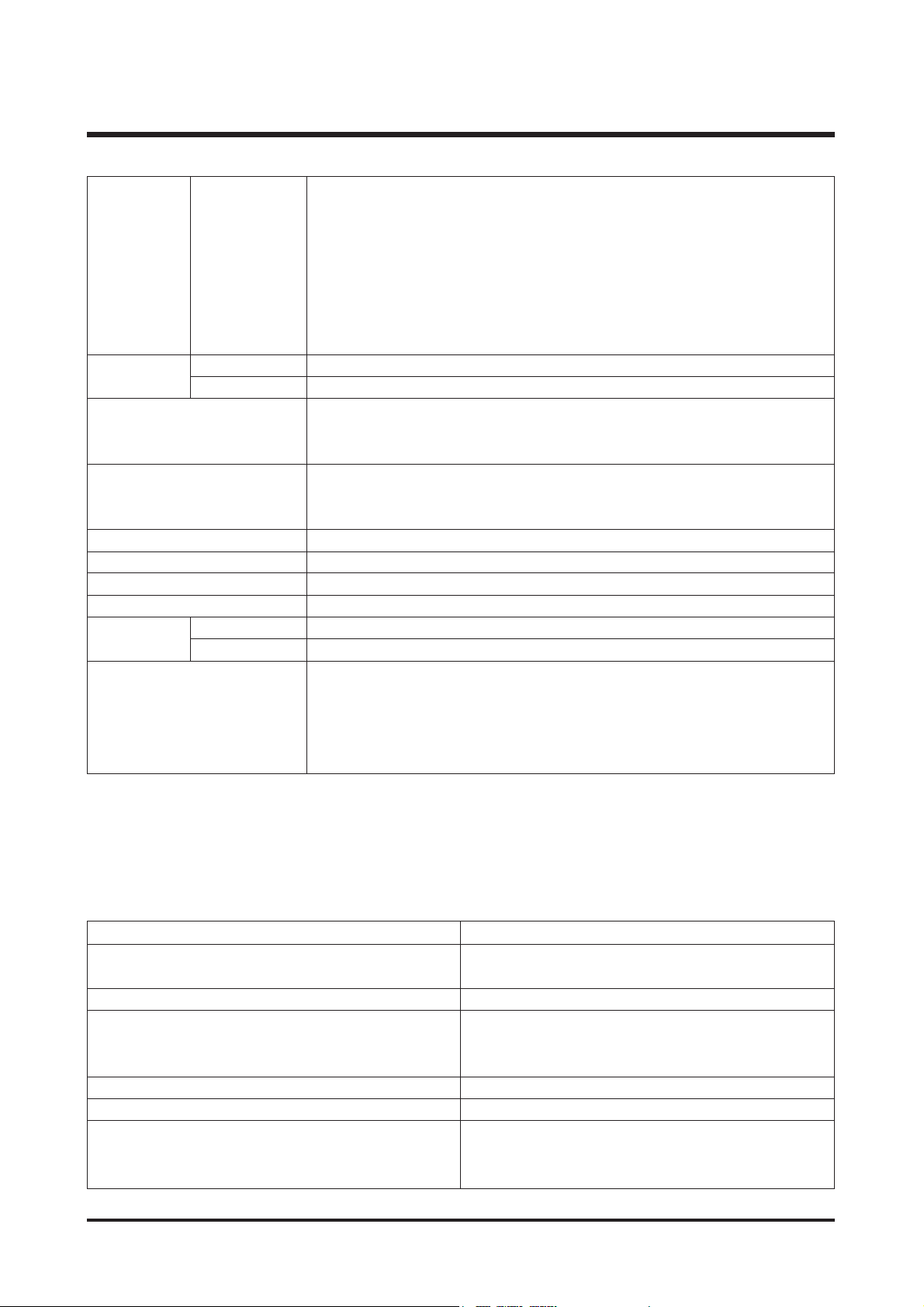
Type 1/2.5" CCD
Effective Pixel Approx. 5.0 Mega-pixel
Total Pixel Approx. 5.1 Mega-pixel
SHD Lens f = 4.6 ~ 22.2mm
(35mm film equivalent : 28 ~ 135mm)
F No. F3.3 ~ F4.8
Still Image mode : 1.0X ~ 5.0X
Play mode : 1.0X ~ 8.0X (depends on image size)
LCD Monitor 2.5" color TFT LCD
Type TTL auto focus
Normal : 60cm ~ infinity
Macro : 2cm ~ 60cm (Wide), 19cm ~ 60cm (Tele)
Auto Macro : 5cm ~ infinity (Wide), 19 ~ infinity (Tele)
Type Mechanical and Electronic shutter
Speed 2~1/1,000 sec. (Night : 8sec~1/1000 sec)
Program AE
Metering : Multi, Spot
Compensation ±2.0EV (0.5EV steps)
ISO Equivalent AUTO, 100, 200, 400
Modes Auto, Auto & Red-eye reduction, Fill-in flash, Slow sync, Flash off
Range Wide : 0.25m ~ 3.0m, Tele : 0.5m ~ 2.0m
Recharging Time
Approx. 5 sec.
Sharpness Soft, Normal, Vivid
Normal, B&W, Sepia, Negative, Red, Green, Blue, RGB, Highlight Frame,
Composite, Photo Frame
White Balance Auto, Daylight, Cloudy, Fluorescent_H, Fluorescent_L, Tungsten, Custom
Voice Recording (max. 1 hour),
Voice Memo in Still Image (max. 10 sec.)
Date Imprinting Off , Date, Date & Time (user selectable)
Modes : Auto, Program, Scene, Voice Recording
Scene : Night, Portrait, Children, Landscape, Close-up, Sunset, Dawn,
Backlight, Fireworks, Beach & Snow
Continuous : Single, Continuous, AEB
Self-timer : 2 sec., 10 sec., Double(10 sec., 2 sec.)
With audio (recording time : memory capacity dependent)
Size : 640x480, 320x240, 160x128
Frame rate : 30fps, 15fps
Internal memory: Approx. 25MB flash memory
External memory: SD card/ MMC (Up to 1GB Guaranteed)
Still Image : JPEG (DCF), EXIF 2.2, DPOF 1.1, PictBridge 1.0
Movie Clip : AVI (MPEG-4) Audio : WAV
5M : 2592x1944 pixels, 4M : 2272x1704 pixels,
3M : 2048x1536 pixels, 2M : 1600x1200 pixels,
1M : 1024x768 pixels, VGA : 640x480 pixels
4
Ⅰ.SPECIFICATION
Image Size
Image Sensor
Lens
Focal Length
Range
Control
Digital Zoom
Focusing
Shutter
Exposure
Flash
Effect
Voice Recording
Shooting
Storage
Movie Clip
Still Image
Media
File Format
1. SPECIFICATION
Page 4
5M: Superfine 9, Fine 18, Normal 26
4M: Superfine 11, Fine 23, Normal 34
3M: Superfine 14, Fine 28, Normal 41
2M: Superfine 23, Fine 44, Normal 64
1M: Superfine 53, Fine 96, Normal 132
VGB : Superfine 117, Fine 189, Normal 238
* These figures are measured under Samsung’s standard conditions and may
vary depending on shooting conditions and camera settings.
Type Single image, Thumbnails, Slide show, Movie Clip, Album mode
Editing Trimming, Rotating, Resizing
Digital output connector : USB 2.0
Audio : Mono
Video output : NTSC, PAL (user selectable) PictBridge
Primary Batteries: 2 x AA alkaline, or CR-V3(Lithium) battery
battery Secondary Batteries : 2 x Ni-MH, Samsung SBP-1303 (Lithium Ion)
* Included battery may vary depending on sales region.
Dimensions (WxHxD) 106.3x56.5x26.7mm
Weight 150g (without battery and card)
Operating Temperature 0 ~ 40°C
Operating Humidity 5 ~ 85%
Camera Driver Storage Driver (Windows98/ 98SE/ 2000/ ME/ XP, Mac OS 9.2 ~ 10.3)
Application ArcSoft PhotoImpression, Digimax Viewer
Optical 4.8X Zoom for Movie & Still image
MPEG-4 VGA 30fps, Supporting Edit on DSC
Various Scene Modes and Effects
(Color Effect, Highlight, Composite, Photo Frame)
Easy Mode Change M Button
5
Ⅰ.SPECIFICATION
Capacity
(25MB)
Storage
Image Play
Power Source
Interface
Software
Special Features
For Windows For Macintosh
PC with processor better than MMX Pentium Power Mac G3 or later
233MHz (XP : Pentium II 300MHz)
Windows 98/98SE/2000/ME/XP Mac OS 9.2~10.3
Minimum 64MB RAM (XP : 128MB) Minimum 64MB RAM
200MB of available hard-disk space 110MB of available hard-disk space
(Over 1GB is recommended)
USB port USB port
CD-ROM drive CD- CD-ROM drive CD1024X768 pixels, 16-bit colour display QuickTime player or a media player that
compatible monitor (24-bit colour display recommended)
supports AVI file format
DirectX 8.1 or later
2. SYSTEM REQUIREMENTS
Page 5
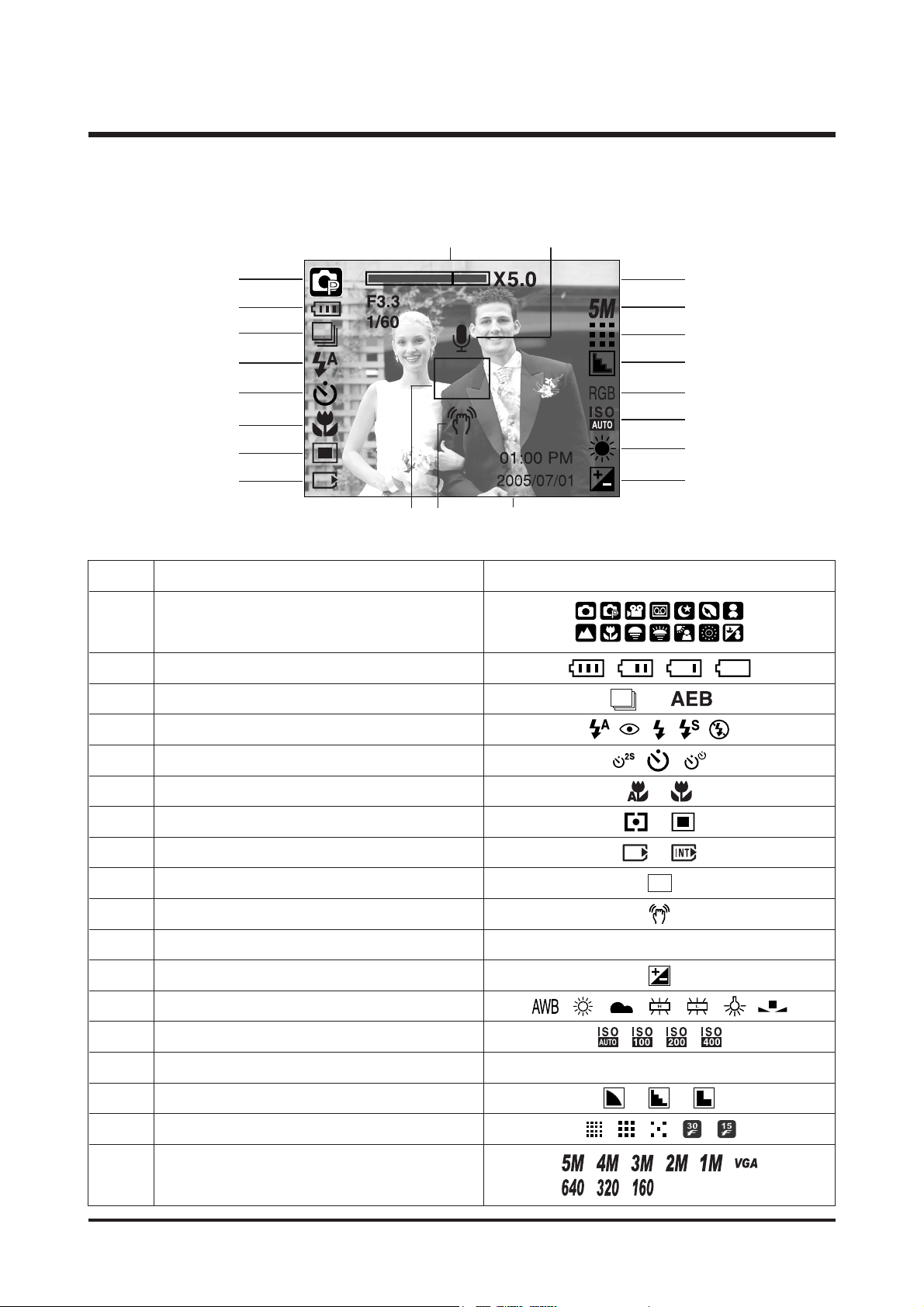
No. Description Icons
2 Battery
3 Continuous shot
4 Flash
5 Self-timer
6 Macro
7 Metering
8 Card inserted indicator
9 Auto focus frame
10 Camera shake warning
11 Date/ Time 2005.07.01 01:00 PM
12 Exposure compensation
13 White Balance
14 ISO
15 RGB RGB
16 Sharpness
17 Image quality
■ Recording Mode
6
Ⅰ.SPECIFICATION
3. TFT LCD PANEL MARK
Recording mode
1
Image size
18
18
①
②
③
④
⑤
⑥
⑦
⑧
⑬
⑫
⑭
⑮
⑰
⑯
⑱
⑲
⑩⑨ ⑪
⑳
Page 6
7
Ⅰ.SPECIFICATION
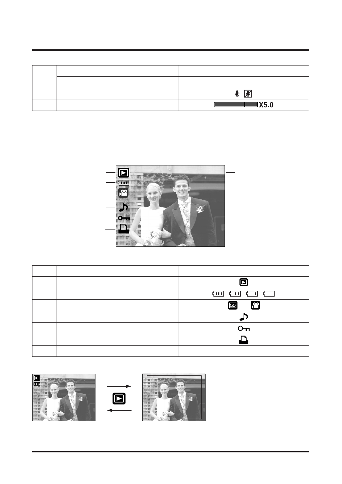
■ Play Mode
100-0009
⑦
②
①
③
④
⑤
⑥
No. Description Icon
1 Play mode
2 Battery
3 File Type
4 Voice memo
5 Protect indicator
6 DPOF indicator
7 Folder name and Stored image number 100-0009
Number of available shots remaining 18
Remaining time (Movie clip/ Voice recording) 00:01:30/ 01:00:00
20 Voice memo/ Mic. off
21
Optical/ Digital Zoom bar/ Digital Zoom rate
SIZE : 2592X1944 Size
AV : F3.3 Aperture value
TV : 1/60S Shutter speed
ISO : 100 ISO sensitivity
FLASH : Off Whether or not
the flash is used
DATE : 2005/07/01 Recording date
100-0009
[Play mode display]
[Recording information]
Pressing for over 1 Sec.
Pressing the Play
mode button
Size : 2592X1944
Av : F3.3
Tv : 1/60S
ISO : 100
Flash : Off
Date : 2005/07/01
19
Page 7
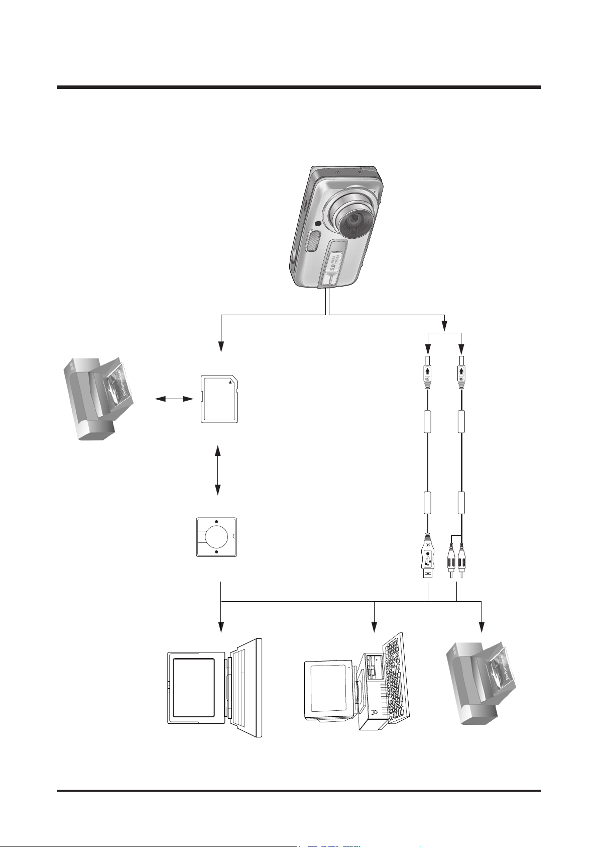
4. CONNECTION DIAGRAM
8
Ⅰ.SPECIFICATION
Lap top
IBM / MAC
USB Cable
MMC Card
DPOF printer
PictBridge printer
AelbaC V
Page 8
9
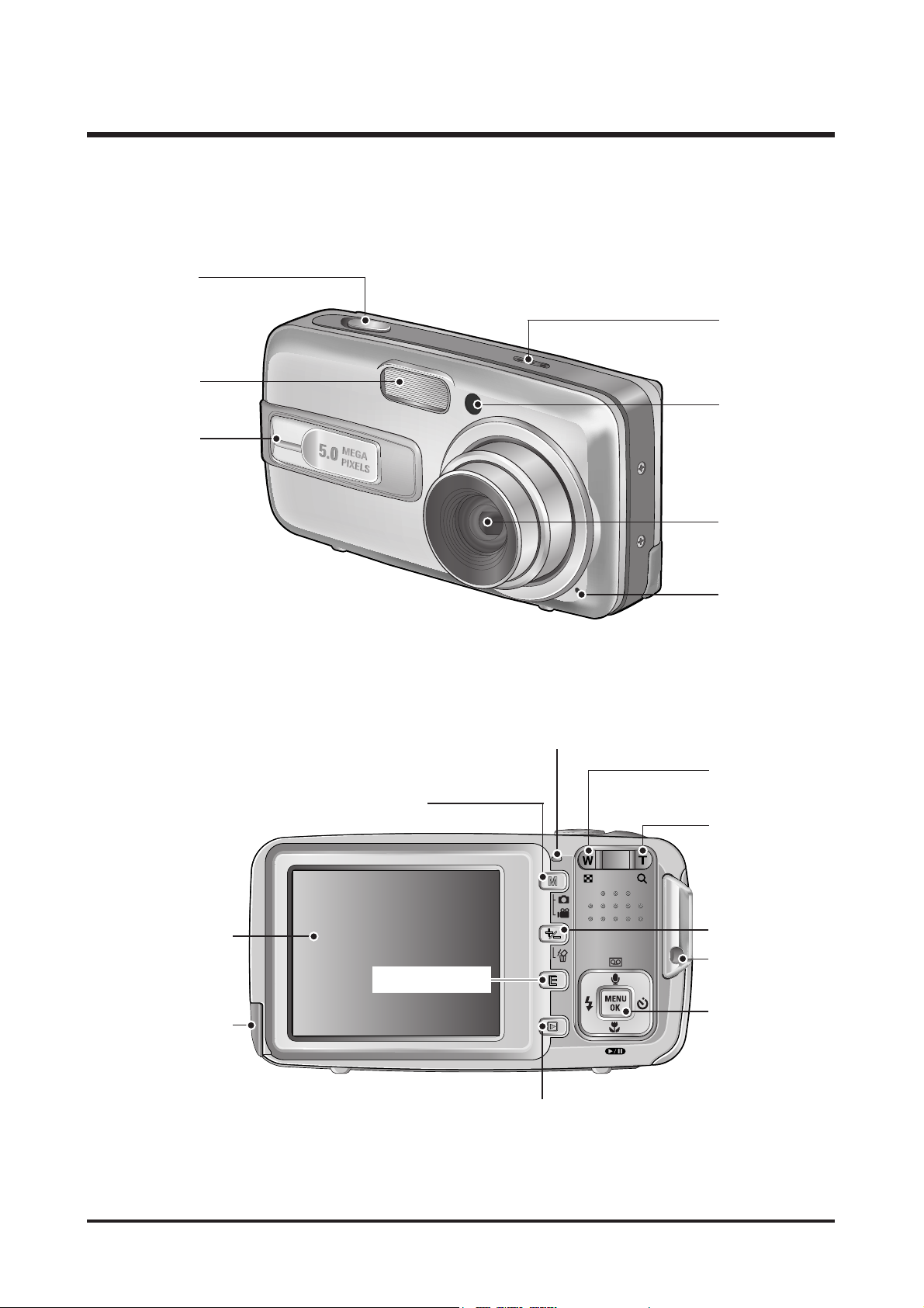
Ⅰ.SPECIFICATION
Flash
Power switch
Shutter button
Self-timer lamp/
Auto Focus lamp
Speaker
Lens
Microphone
5. IDENTIFICATION OF FEATURES
LCD monitor
USB/
AV connection
terminal
Play mode button
5 function button
E (Effect) button
Strap eyelet
Zoom T button
(Digital zoom)
Camera status lamp
Zoom W button
(Thumbnail)
M(Mode/ Album) button
+/-, DELETE button
Page 9
10
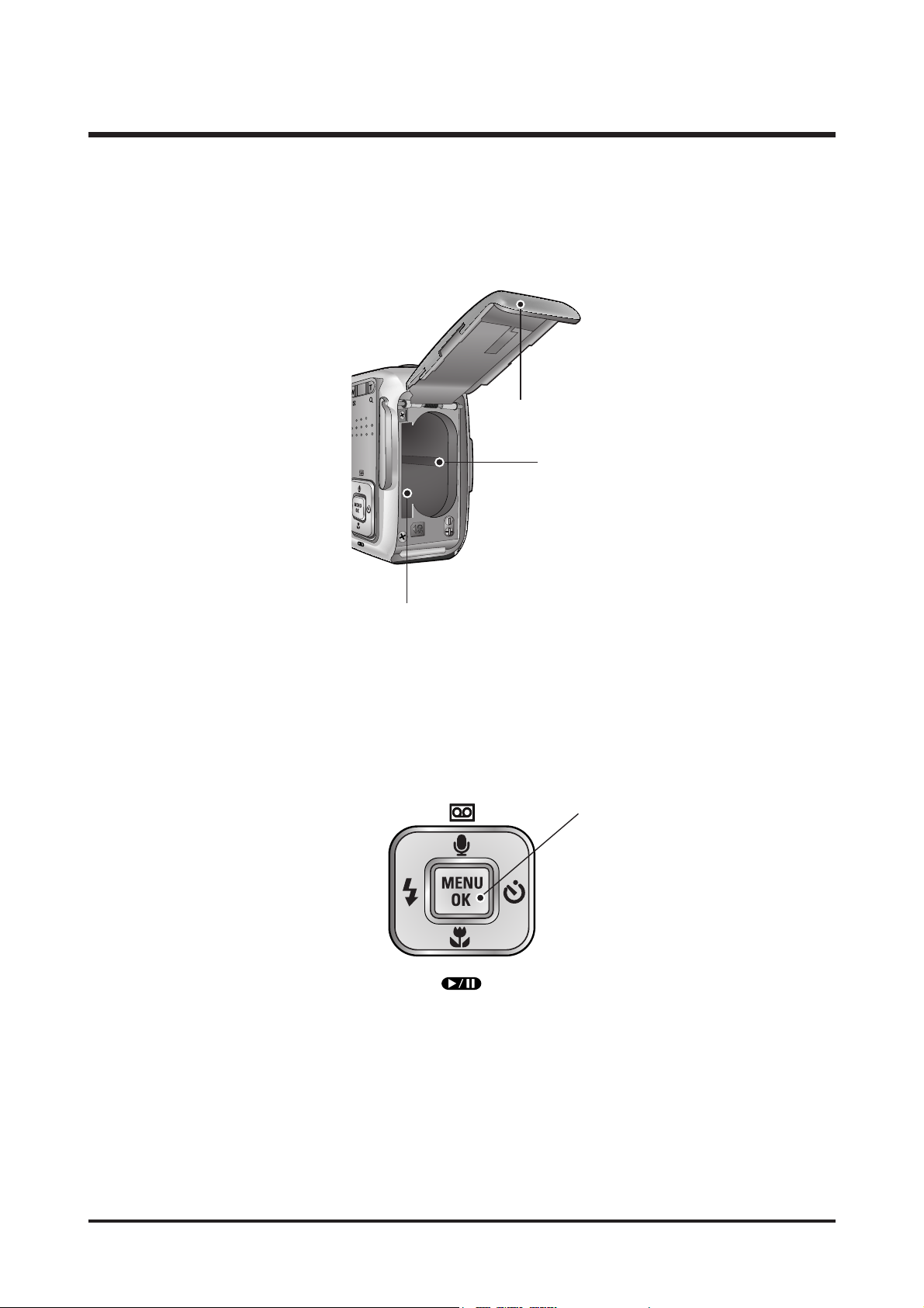
Ⅰ.SPECIFICATION
FLASH/
LEFT button
MENU/
OK button
Macro/ DOWN button
Play & Pause button
SELF-TIMER/
RIGHT button
Voice memo/ Voice recording/ UP button
Battery chamber
Memory card slot
Battery chamber cover
Page 10
11
Ⅱ.INSTALLATION
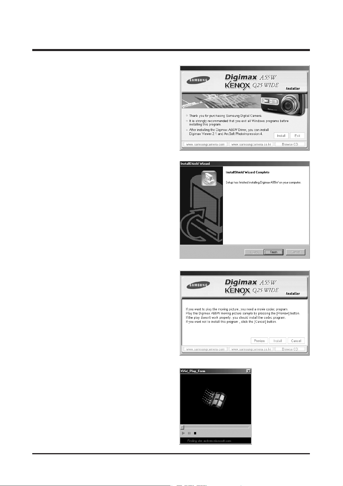
1. Click the [Install] menu in the Autorun frame.
The camera driver is installed automatically.
2. Installation is complete.
Click the [Finish] button.
3. A windows to check whether the PC has XviD codec
or not will display.
[Preview] : You can check the movie clip display
condition.
[Install] : The XviD codec is installed.
[Cancel] : The XviD codec is not installed and a
window for installing the application
softwares will display.
※ If you didn’t click the [Preview] button, the [Install]
button can’t be selected.
4. If an error listed below takes place during the
preview, click the [Install] button to install the XviD
codec.
- Only a voice plays back.
- An error message displays and the movie clip
does not play back.
Page 11
12
Ⅱ.INSTALLATION
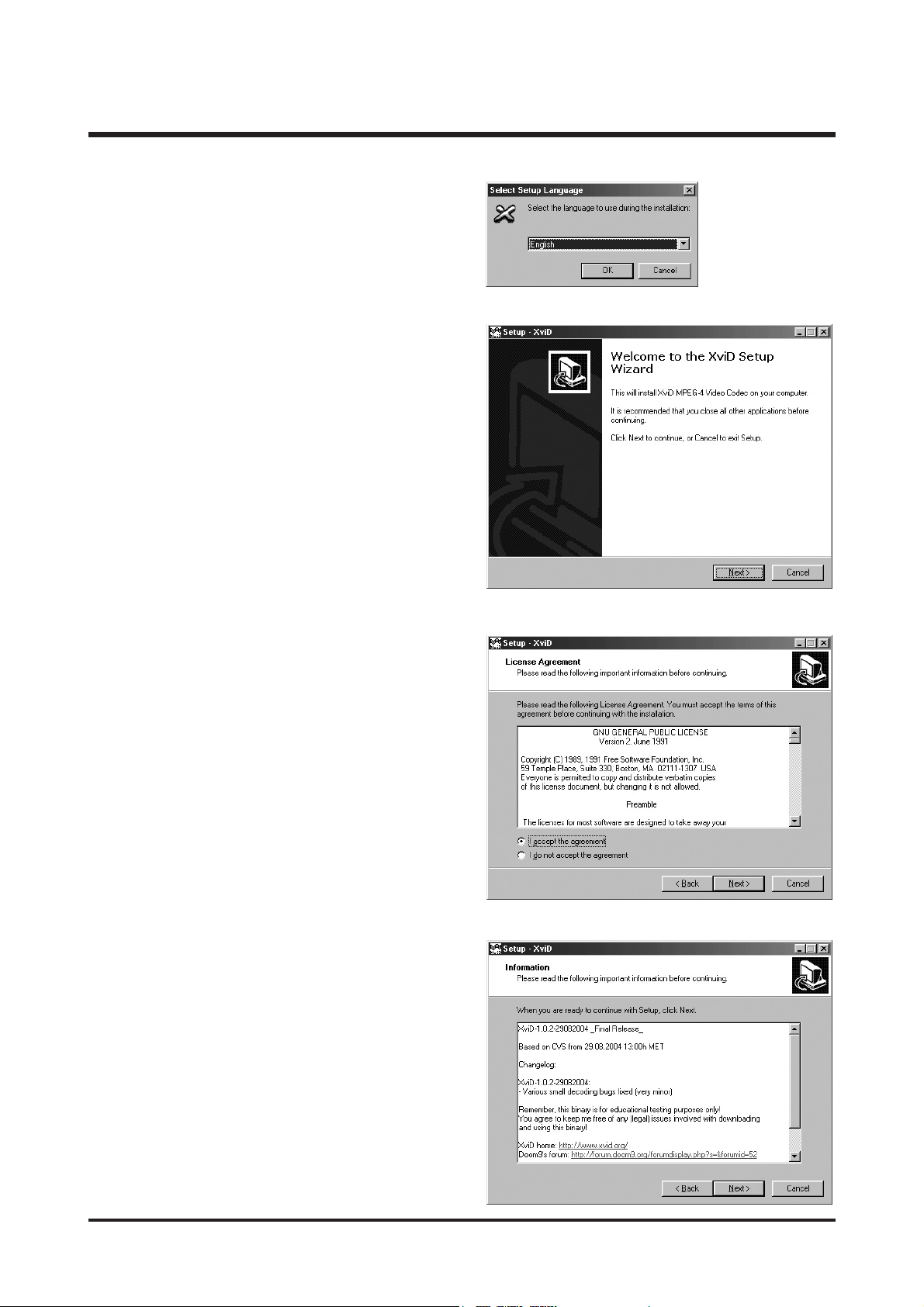
7. The XviD information window will display.
Click the [Next >] button.
6. The Software License Agreement window will be
displayed. If you agree to this, select [I accept the
agreement] and click [Next >] button. The window
will then move to the next step. If you disagree,
select
[I do not accept the agreement] and click [Cancel]
button. The installation program will be cancelled.
※ The XviD codec is distributed according to the
GNU General Public License and everyone can
copy, distribute and change this codec. For more
information, see the License documents.
* A window shown alongside may display
according to the system requirements.
5. The XviD codec installation window will be
displayed as shown alongside.
Click the [Next >] button.
Page 12
13
Ⅱ.INSTALLATION
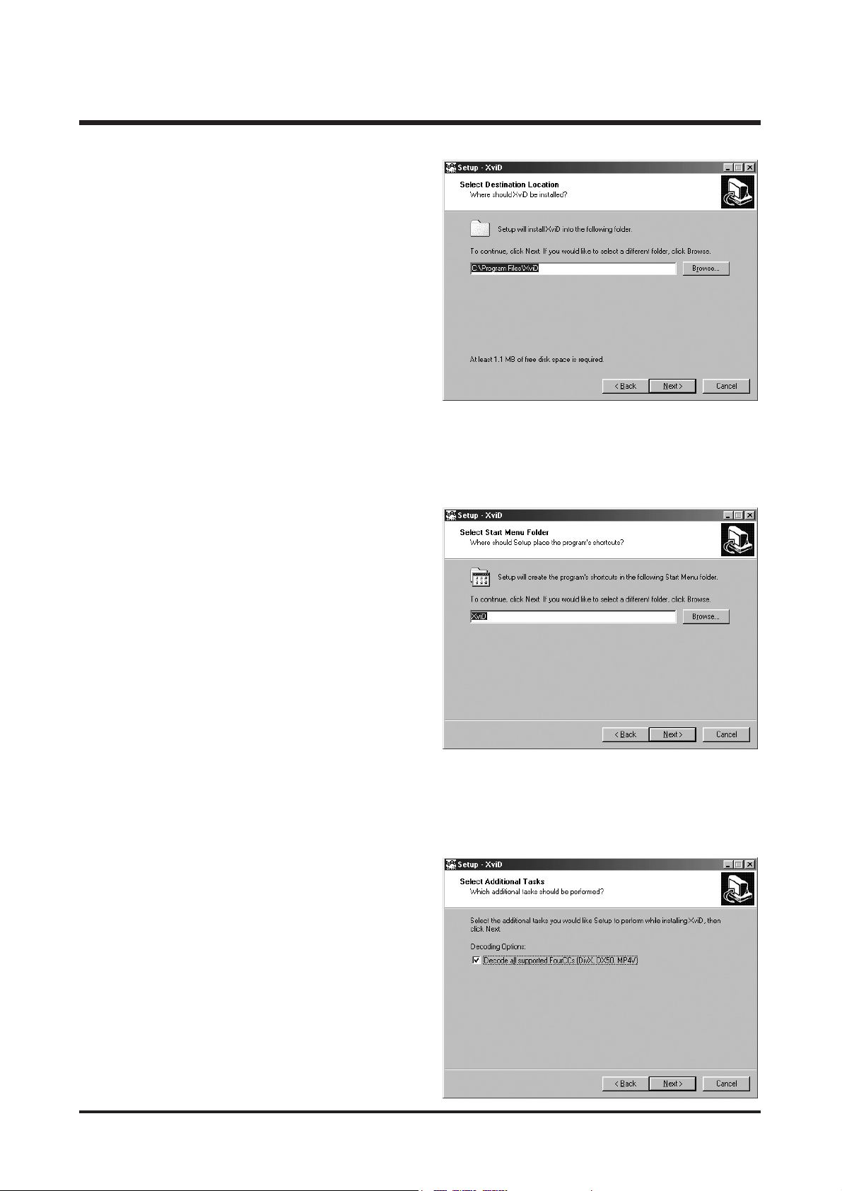
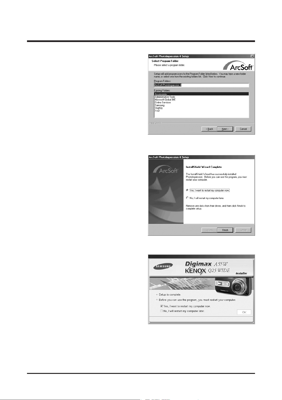
9. A window will open, asking you to choose a folder to
which program icons will be added.
Click [Next >] button.
If you want to add the program icons to a different
folder, choose another folder, and then click [Next >]
button.
8. The destination selection window will open.
Click [Next >] button.
To copy to the files to another folder, click
[Browse...] and choose a folder you want.
10. The [Select Additional Tasks] window will display.
Select the additional tasks and click the [Next >]
button.
Page 13
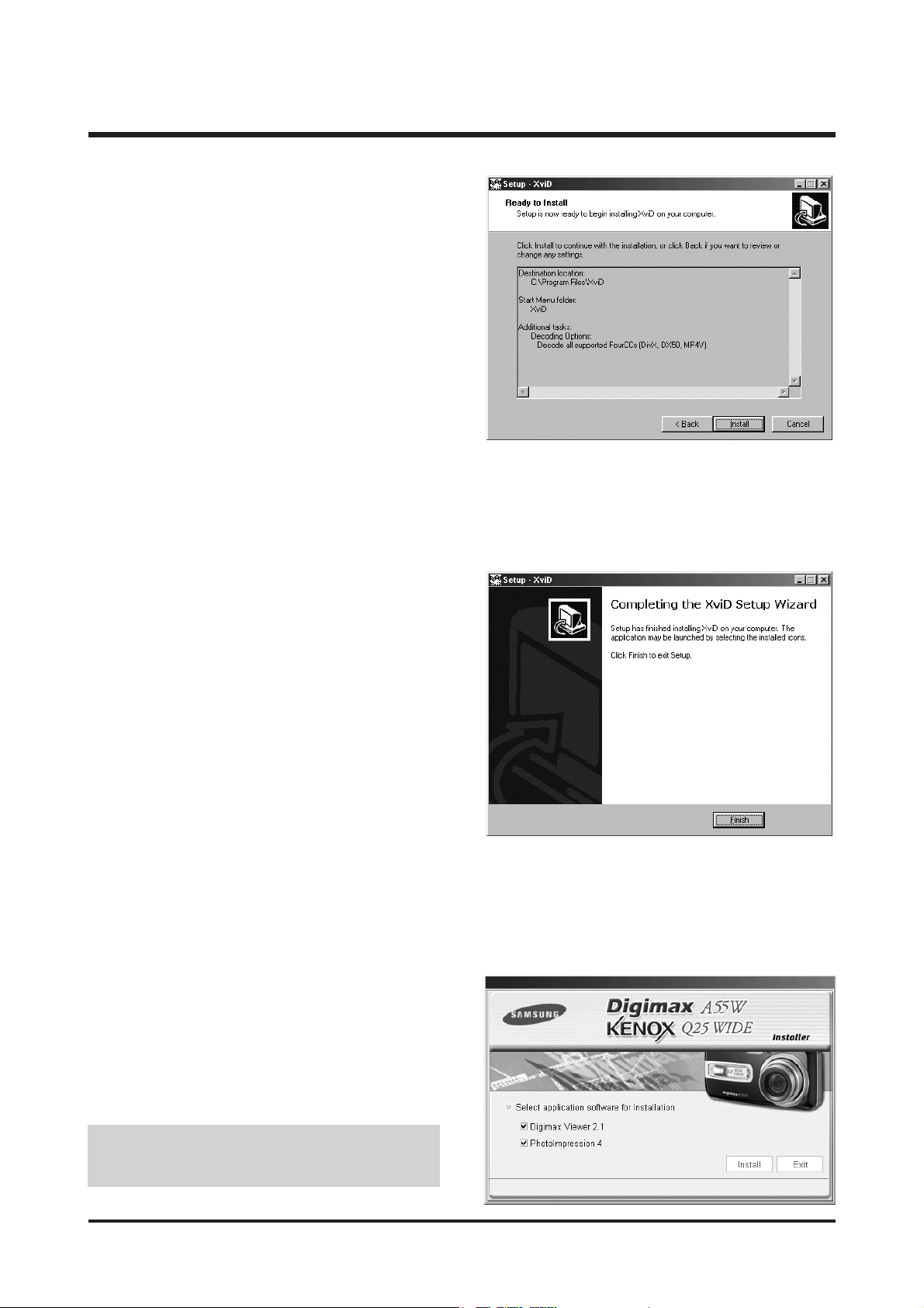
12. Installation is complete.
Click the [Finish] button.
13. A window where you can choose the program you
want to install will appear. Click [Install].
● If you select [Exit] at step 13, the application
program installation will be cancelled.
14
Ⅱ.INSTALLATION
11. The XviD codec is ready to install.
Click the [Install] button.
Page 14
15
Ⅱ.INSTALLATION
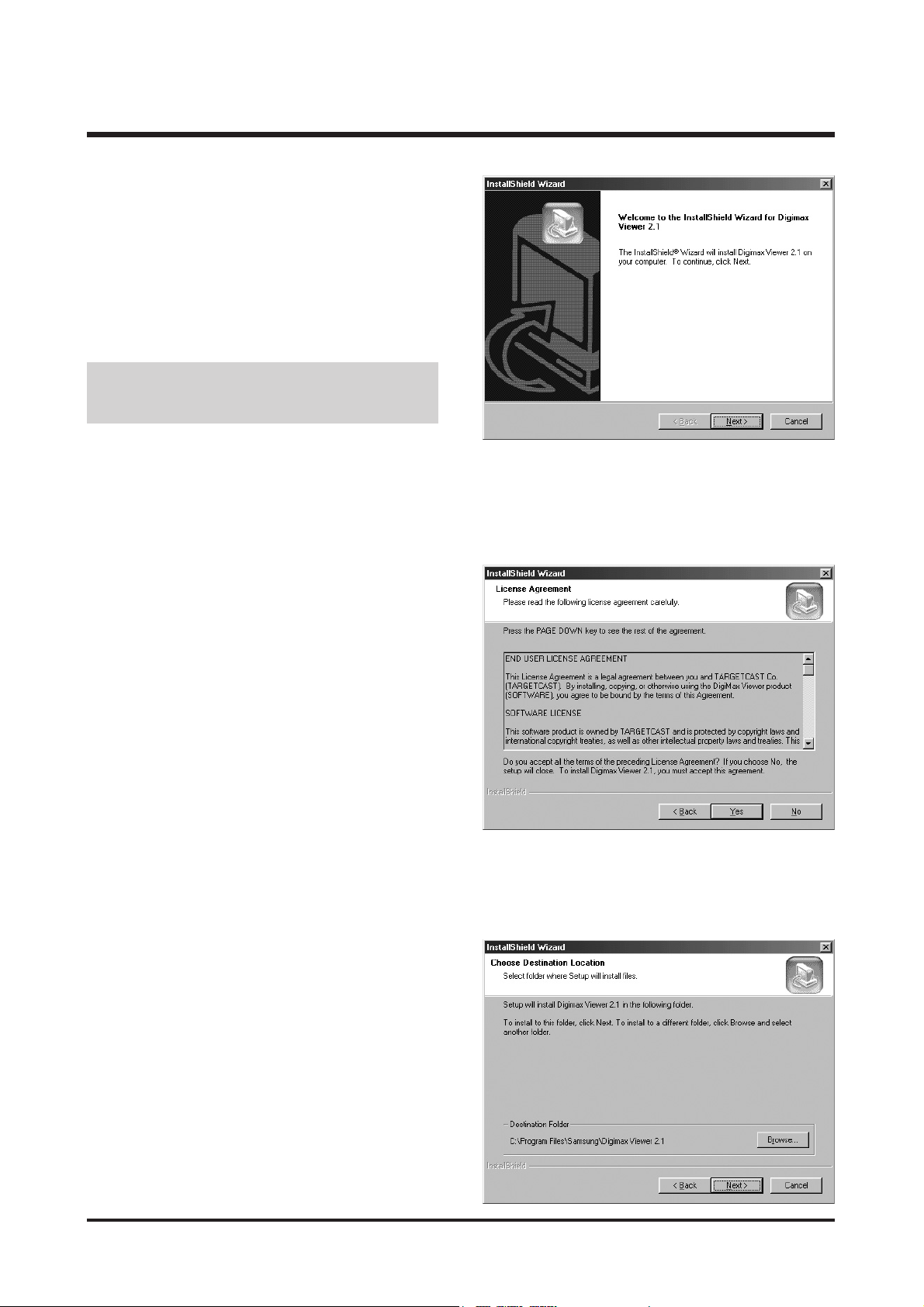
14. The [Digimax Viewer 2.1] installation window will
be displayed as shown alongside.
Click the [Next >] button.
15. The Software License Agreement window will be
displayed.
If you agree to this, click [Yes], the window will
then move to the next step.
If you disagree, click [No] and the installation
program will be cancelled.
● If you select [Cancel] at step 14, a window for
installing Digimax Reader will be displayed.
16. A destination selection window will open.
Click [Next >].
To copy to the files to another folder, click
[Browse..] and choose a folder you want.
Page 15
16
Ⅱ.INSTALLATION
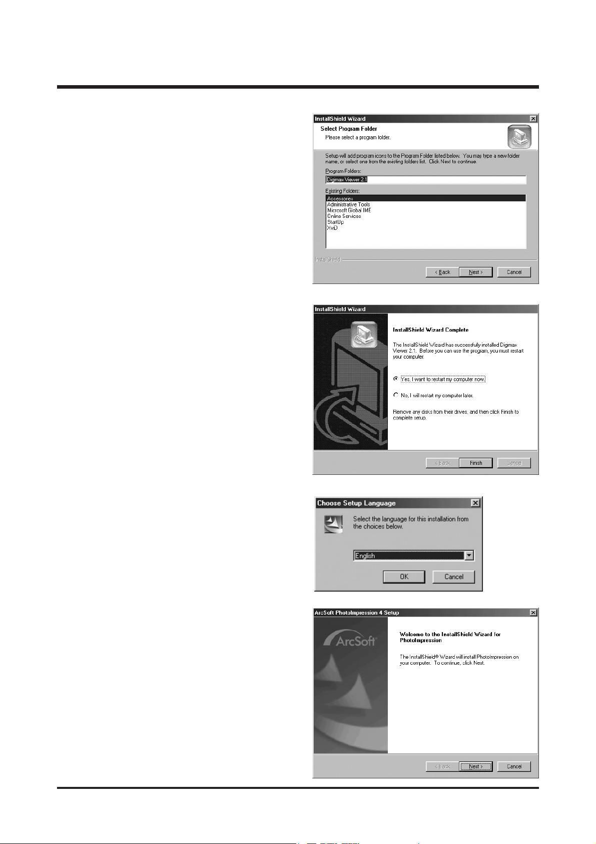
20. A Welcome window will be displayed.
Click the [Next >] button.
17. A window will open, asking you to choose a folder
to which program icons will be added.
Click [Next >] button.
18. Digimax Viewer installation is successfully
completed. Click the [Finish] button to install
PhotoImpression.
* The system will not reboot even the [Yes, I want to
restart the computer now] option is selected.
* The screen shot of step 18 can be different with
the illustration according to the system
requirements.
19. The PhotoImpression installation window will be
displayed as shown alongside.
Click the [OK] button.
Page 16

17
Ⅱ.INSTALLATION
22. A destination selection window will open.
Click [Next >]. To copy the files to another folder,
click [Browse...] and choose a folder you want.
23. The [Select Components] window will appear.
Click [Next >] button.
21. The Software License Agreement window will be
displayed.
If you agree to this, click [Yes], the window will
then move to the next step.
If you disagree, click [No] and the installation
program will be cancelled.
Page 17
18
Ⅱ.INSTALLATION
26. To apply changes, you must restart the computer.
Select [Yes, I want to restart my computer now],
and then click [Finish].
27. After restarting the computer, connect the PC to the camera with the USB cable.
24. A window will open, asking you to choose a folder
to which program icons will be added.
Click [Next >] button. If you want to add the
program icons to a different folder, choose another
folder, and then click [Next >] button.
25. PhotoImpression Installation is completed.
Click the [Finish] button.
* The system will not reboot even if the [Yes, I want
to restart the computer now] option is selected.
* The frame that appears may be different to that
shown according to the system requirements.
Page 18
19
Ⅱ.INSTALLATION
28. Turn the camera power on.
[Found New Hardware Wizard] will open and the
computer will recognise the camera.
* If you have ever installed an image viewer
program or your OS is Windows XP, an image
viewer program will open.
If the image viewer program opens, the camera
driver was setup successfully.
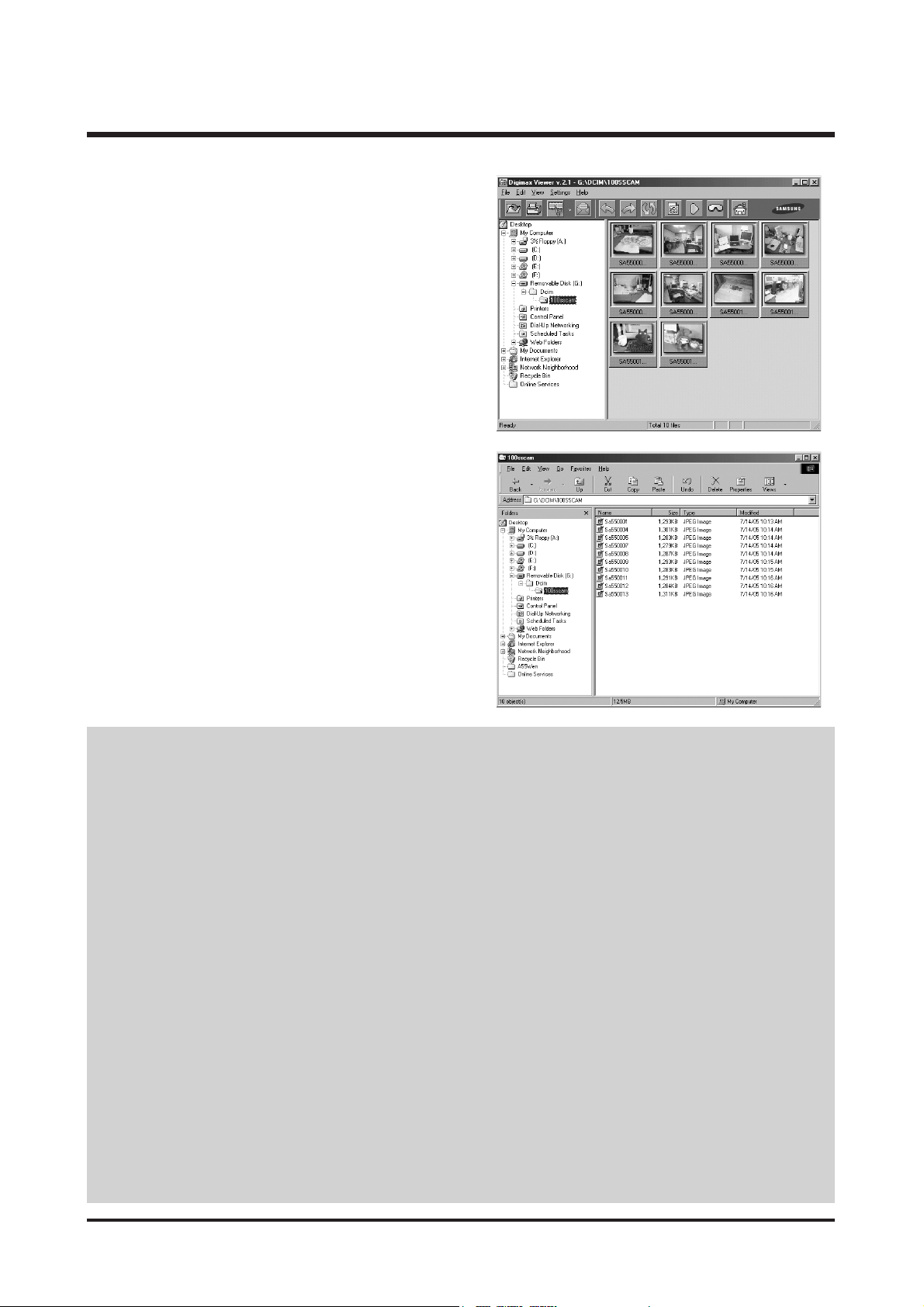
29. If you can see [Removable Disk] under
[My computer], the camera driver installation was
successful.
Now you can transfer image files from the camera
to PC via the USB cable.
● If you have installed the camera driver, [Found New Hardware Wizard] may not open.
● On a Windows 98 or 98 SE system, the Found New Hardware Wizard dialog box opens
and a window asking you to select a driver file may appear. In this case, specify "USB
Driver" in the CD supplied. (for Windows 98 and 98 SE).
● Before connecting the camera to the PC, You should first install the camera driver.
● After installing the camera driver, you have to restart your PC.
● If you connect the camera to the PC before installing the camera driver, the [Found New
Hardware Wizard] will open.
In this case, cancel the [Found New Hardware Wizard] and disconnect the camera.
Install the camera driver and connect the camera to the PC again.
● Should the computer not find the camera driver after installation, please try one or more
of the following measures.
1. Delete the camera driver, and re-install the driver.
2. Refer to FAQ to check for a possible solution to the problem.
3. If your PC’s central processing unit is VIA chip (This is shown in the USB Host
Controller), download the patch file from the Samsung Camera web page.
(http://www.samsungcamera.com)
Page 19
20
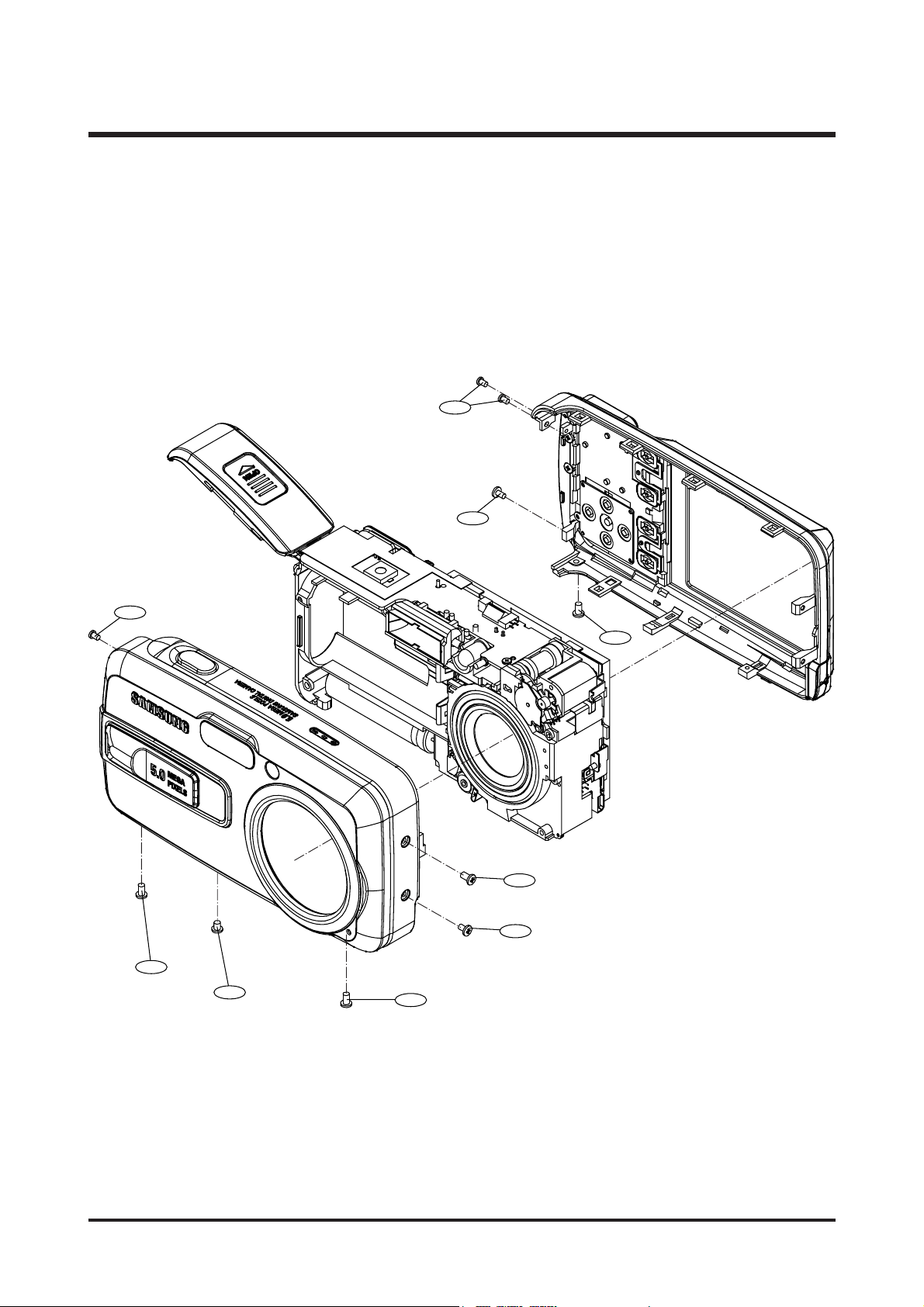
Ⅲ.EXPLODEDVIEWANDPARTLIST
1-1
1-3
1-1
1-5
1-2
1-1
1-4
1-5
1-4
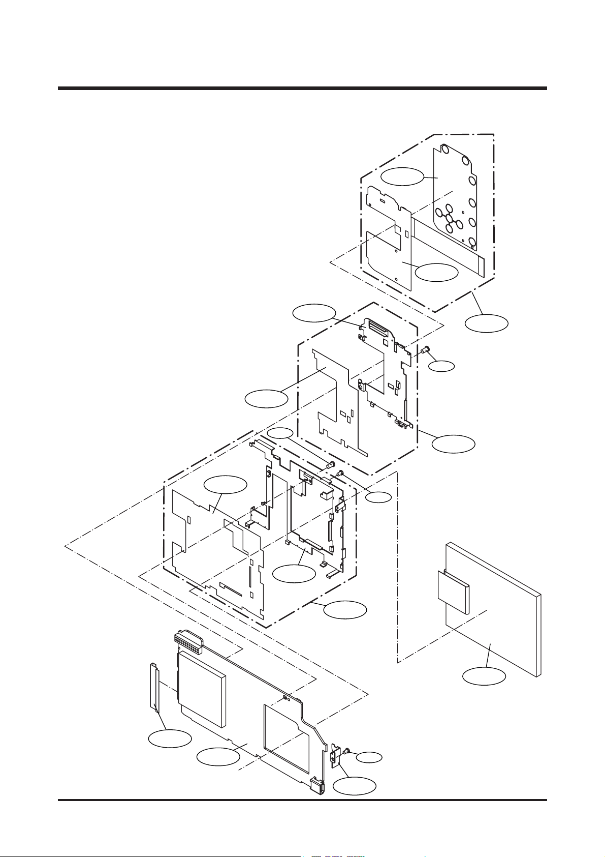
1. MAIN ASSEMBLY
Page 20

21
Ⅲ.EXPLODEDVIEWANDPARTLIST
▶
PARTS LIST
1-1 Q6002028801A TAPPING SCREW 3 X
1-2 Q6002028701A TAPPING SCREW 1 X
1-3 Q6002028601A TAPPING SCREW 1 X
1-4 Q6002028201A TAPPING SCREW 2 X
1-5 Q6002028901A TAPPING SCREW 3 X
Fig.No Parts No. Parts Name Q’ty
Supply Available Parts
Remarks
Page 21
22
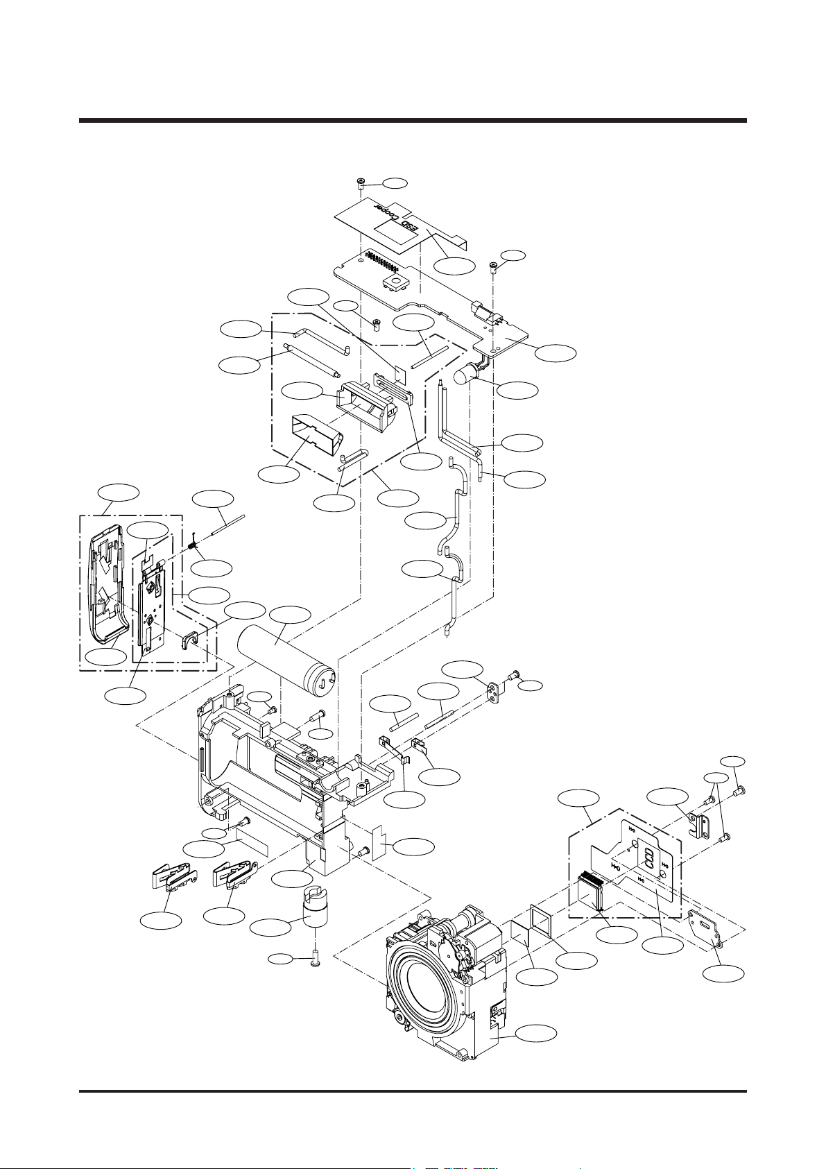
Ⅲ.EXPLODEDVIEWANDPARTLIST
2-49
2-8
2-9
2-10
2-11
2-12
2-13
2-19
2-20
2-21
2-23
2-18
2-25
2-26
2-22
2-24
2-14
2-15
2-16
2-43
2-42
2-41
2-40
2-39
2-38
2-37
2-36
2-33
2-31
2-34
2-29
2-28
2-27
2-35
2-32
2-30
2-17
2-3
2-1
2-7
2-4
2-6
2-2
2-5
2-44
2-44
2-44
2-44
2-45
2-47
2-46
2-44
2-44
2-48
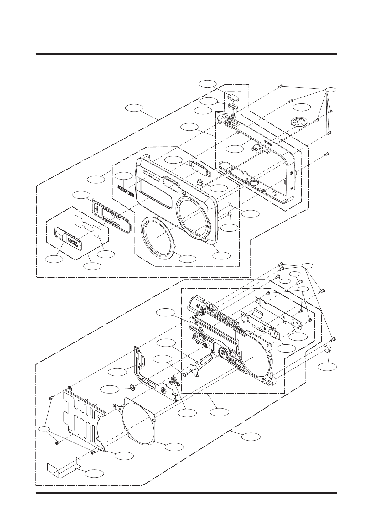
2. BODY ASSEMBLY
Page 22

23
Ⅲ.EXPLODEDVIEWANDPARTLIST
▶
PARTS LIST
2-1 Q7217364801A BATTERY COVER 1 O SILVER
Q7217364901A BATTERY COVER 1 O BLACK
2-2 Q7409207501A BATTERY COVER SPONGE 1 X
2-3 Q7204026501A BATTERY STOPER 1 O
2-4 Q6107066701A BATTERY COVER SPRING 1 O
2-5 Q6119397101A BATTERY SPRING AXLE 1 O
2-6 Q9010052301A BATTERY COVER-1 ASS'Y 1 O
2-7 Q9007245401A BATTERY COVER ASS'Y 1 O SILVER
Q9007245501A BATTERY COVER ASS'Y 1 O BLACK
2-8 Q7001006301A BATTERY CASE CON A 1 O
2-9 Q7011054901A BATTERY CASE CON B 1 O
2-10 Q7409206701A STCAP TAPE 1 X
2-11 Q7111002501A TRIPOD 1 O
2-12 Q7204026401A BATTERY CASE 1 O
2-13 Q7409207101A BAT PROTECT TAPE 1 X
2-14 Q7001005901A BATTERY CHECK B 1 O
2-15 Q7001005801A BATTERY CHECK A 1 O
2-16 Q0102016601A WIRE-RED 1 X
2-17 Q0102016701A WIRE-BLACK 1 X
2-18 Q7001006801A LENS FIX PLATE C 1 O
2-19 Q9002146001A RICOH LENS 1 O
2-20 Q2904003501A OLPF 1 O
2-21 Q7309047701A CCD RUBBER 1 O
2-22 Q0604005701A CCD 1 X
2-23 Q7001006901A CCD PLATE 1 O
2-24 Q9008093701A CCD F PCB SMD 1 X
2-25 Q9008093501A CCD F PCB ASS'Y 1 O
2-26 Q7001006701A LENS FIX PLATE A 1 O
2-27 Q0607001001A FLASH REFLECTOR 1 X
2-28 Q7204026801A FLASH HOLDER 1 X
2-29 Q0611004801A FLASH TUBE XE 1 O
2-30 Q7309044801A FLASH RUBBER 1 X
2-31 Q7409206401A REFLECTOR COPPER 1 X
2-32 Q0102016301A FLASH WIRE-BLACK 1 X
2-33 Q0102016401A FLASH WIRE-RED 1 X
2-34 Q0102016501A FLASH WIRE-WHITE 1 X
2-35 Q9004085601A FLASH ASS'Y 1 O
2-36 Q7409206501A SHUTTER COPPER 1 O
2-37 Q9008093401A SHUTTER PCB 1 O
2-38 Q0601006801A LED 1 O
2-39 Q0102017001A BAT WIRE-RED 1 X
2-40 Q0102016901A BAT WIRE-BLACK 1 X
2-41 Q0102016201A CAP WIRE-RED 1 X
2-42 Q0102016801A CAP WIRE-BLACK 1 X
2-43 Q2401009401A FLASH CAP 1 O
2-44 Q6002027801A TAPPING SCREW 7 X
2-45 Q6002028301A TAPPING SCREW 1 X
2-46 Q6002028901A TAPPING SCREW 1 X
2-47 Q6002027901A TAPPING SCREW 1 X
2-48 Q6002028001A TAPPING SCREW 2 X
2-49 Q7101001501A BAT COVER CONTACT 1 X
Fig.No Parts No. Parts Name Q’ty
Supply Available Parts
Remarks
Page 23
24
Ⅲ.EXPLODEDVIEWANDPARTLIST
3-1
3-2
3-3
3-4
3-5
3-9
3-12
3-13
3-10
3-11
3-7
3-8
3-6
3-14
3-15
3-15
3-14
3. BODY ASSEMBLY
Page 24

25
Ⅲ.EXPLODEDVIEWANDPARTLIST
▶
PARTS LIST
3-1 Q7409207201A SOCKET TAPE-B 1 X
3-2 Q9008093301A MAIN BOARD 1 O
3-3 Q7001006601A LENS FIX PLATE B 1 O
3-4 Q7409206901A LCD TAPE 1 X
3-5 Q7001006401A LCD PLATE 1 X
3-6 Q9010052701A LCD PLATE + TAPE 1 O
3-7 Q7409206801A KEY HOLDER TAPE 1 X
3-8 Q7001006501A KEY HOLDER 1 X
3-9 Q9010052601A KEY HOLDER+TAPE 1 O
3-10 Q0109000401A METAL DOME 1 X
3-11 Q9008094501A KEY F PCB ASS'Y 1 X
3-12 Q9008093601A METAL DOME+KEY F PCB 1 O
3-13 Q0704012001A LCD PANNEL 1 O
3-14 Q6002028401A TAPPING SCREW 2 X
3-15 Q6002027801A TAPPING SCREW 2 X
Fig.No Parts No. Parts Name Q’ty
Supply Available Parts
Remarks
Page 25
26
Ⅲ.EXPLODEDVIEWANDPARTLIST
4-1
4-2
4-5
4-6
4-12
4-13
4-14
4-15
4-16
4-19
4-20
4-17
4-7
4-8
4-9
4-10
4-11
4-3
4-4
4-18
4. FRONT ASSEMBLY
4-22
4-23
4-24
4-21
4-27
4-28
4-31
4-32
4-34
4-35
4-36
4-29
4-30
4-25
4-39
4-26
4-38
4-37
4-33
Page 26

27
Ⅲ.EXPLODEDVIEWANDPARTLIST
▶
PARTS LIST
4-1 Q7217365601A POWER KEY-SILVER 1 X SILVER
Q7217365701A POWER KEY-BLACK 1 X BLACK
4-2 Q7409207001A POWER TAPE 1 X
4-3 Q9007245601A POWER KEY ASS'Y 1 O SILVER
Q9007245701A POWER KEY ASS'Y 1 O BLACK
4-4 Q7217365001A FRONT GRIP 1 O SILVER
Q7217365101A FRONT GRIP 1 O BLACK
4-5 Q7117012401A LENS RING-SILVER 1 X SILVER
Q7117012501A LENS RING-BLACK 1 X BLACK
4-6 Q7217303501A SAMSUNG LOGO 1 X
4-7 Q7217364301A FRONT COVER-Digimax 1 X SILVER
Q7217364401A FRONT COVER-Digimax 1 X BLACK
Q7217366201A FRONT COVER-Kenox 1 X SILVER
Q7217366301A FRONT COVER-Kenox 1 X BLACK
4-8 Q7209002701A FLASH COVER 1 X
4-9 Q7209002501A AF WINDOW 1 X
4-10 Q6002028501A TAPPING SCREW 1 X
4-11 Q7409207401A SLIDER SPONGE 1 X
4-12 Q9007244901A FRONT COVER SUB ASS'Y-Digimax 1 O SILVER
Q9007245001A FRONT COVER SUB ASS'Y-Digimax 1 O BLACK
Q9007246001A FRONT COVER SUB ASS'Y-Kenox 1 O SILVER
Q9007246101A FRONT COVER SUB ASS'Y-Kenox 1 O BLACK
4-13 Q7217364701A MIDDLE COVER 1 X
4-14 Q6107066601A SHUTTER KEY SPRING 1 O
4-15 Q7204026701A SHUTTER KEY HOLDER 1 O
4-16 Q7211082501A SHUTTER KEY 1 O
4-17 Q9007245201A MIDDLE COVER ASS'Y 1 O
4-18 Q6002027801A TAPPING SCREW 6 X
4-19 Q9007244801A FRONT COVER ASS'Y-Digimax 1 O SILVER
Q9007244701A FRONT COVER ASS'Y-Digimax 1 O BLACK
Q9007245901A FRONT COVER ASS'Y-Kenox 1 O SILVER
Q9007245801A FRONT COVER ASS'Y-Kenox 1 O BLACK
4-20 Q3001000901A SPEAKER 1 O
4-21 Q7204026601A SLIDE COVER HOLDER 1 X
4-22 Q9010052801A SLIDE F PCB ASS'Y 1 X
4-23 Q7001006201A SLIDE COVER F PC PLATE 1 X
4-24 Q7001006001A SLIDE COVER CON ROB C 1 X
4-25 Q6119397201A SLIDER COVER AXIE 1 X
4-26 Q6002028401A TAPPING SCREW 3 X
4-27 Q9010052401A SLIDE COVER SUB ASS'Y 1 O
4-28 Q6107066501A SLIDE COVER SPRING 1 O
4-29 Q7001006101A SLIDE COVER CON ROB B 1 O
4-30 Q6002028101A TAPPING SCREW 1 X
4-31 Q7101001601A SLIDER COVER 1 O
4-32 Q7001005701A SLIDER COVER PLATE 1 O
4-33 Q6002028401A TAPPING SCREW 3 X
4-34 Q7409206601A FRONT COPPER 1 X
4-35 Q9010052501A SLIDE COVER ASS'Y 1 O
4-36 Q3003000901A MICROPHONE 1 O
4-37 Q6002027801A TAPPING SCREW 4 X
4-38 Q6002029001A TAPPING SCREW 1 X
4-39 Q6002028001A TAPPING SCREW 4 X
Fig.No Parts No. Parts Name Q’ty
Supply Available Parts
Remarks
Page 27
28
Ⅲ.EXPLODEDVIEWANDPARTLIST
5-1
5-3
5-4
5-6
5-7
5-8
5-9
5-10
5-11
5-2
5-12
5-13
5-5
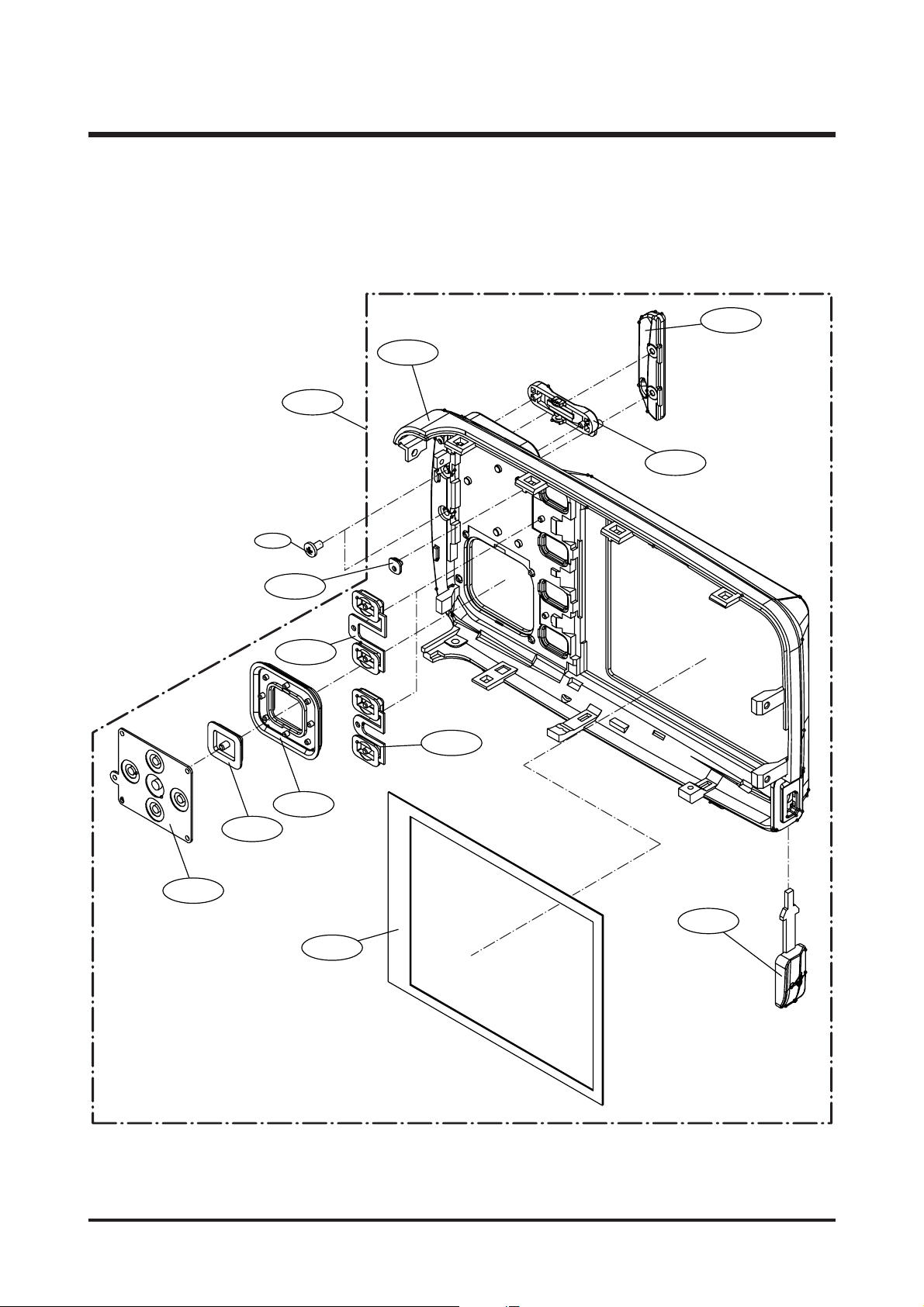
5. BACK COVER ASSEMBLY
Page 28

29
Ⅲ.EXPLODEDVIEWANDPARTLIST
▶
PARTS LIST
5-1 Q7217364501A BACK COVER-SILVER 1 X SILVER
Q7217364601A BACK COVER- BLACK 1 X BLACK
5-2 Q7409207301A LCD SPONGE 2 X
5-3 Q7209002601A LED GUIDE BACK 1 X
5-4 Q7209002301A STRAP-SILVER 1 O SILVER
Q7209002401A STRAP-BLACK 1 O BLACK
5-5 Q6002028201A TAPPING SCREW 2 X
5-6 Q7217365401A ZOOM KEY-SILVER 1 O SILVER
Q7217365501A ZOOM KEY-BLACK 1 O BLACK
5-7 Q7217365801A MODE KEY A-SILVER 1 O SILVER
Q7217365901A MODE KEY A-BLACK 1 O BLACK
5-8 Q7217366001A MODE KEY B-SILVER 1 O SILVER
Q7217366101A MODE KEY B-BLACK 1 O BLACK
5-9 Q7209002101A OK BUTTON-SILVER 1 O SILVER
Q7209002201A OK BUTTON-BLACK 1 O BLACK
5-10 Q7217365201A DIRECTION BUTTON-SILVER 1 O SILVER
Q7217365301A DIRECTION BUTTON-BLACK 1 O BLACK
5-11 Q7307006601A 5 WAY KEY RUBBER 1 X
5-12 Q7308015601A USB RUBBER 1 O
5-13 Q9007245101A BACK COVER ASS'Y-SILVER 1 O SILVER
Q9007245301A BACK COVER ASS'Y-BLACK 1 O BLACK
Fig.No Parts No. Parts Name Q’ty
Supply Available Parts
Remarks
Page 29

30
Ⅲ.EXPLODEDVIEWANDPARTLIST
6. PACKING ITEM
6-11 6-20 6-17 6-18
6-12 6-13
6-19
6-15
6-16
6-1
6-4
6-7
5-10
6-8
6-5
6-9
6-2
6-14
6-6
6-3
Page 30

31
Ⅲ.EXPLODEDVIEWANDPARTLIST
▶
PARTS LIST
6-1 QP960210101A PE BAG (FOR CAMERA) 1 O
6-2 Q6909011601A PE BAG (FOR ACCESSORY) 1 O
6-3 Q6909017301A
AIR BAG_Digimax A55W(FOR CAMERA)
1O
6-4 Q6909017801A
AIR BAG_Digimax A55W(FOR POUCH)
1O
6-5 Q6901215101A
INNER PAD_D Digimax A55W_KOR/EXP
1O
6-6 Q6904027601A POUCH_Digimax A55W (SAMSUNG) 1 O
6-7 Q6806281101A Q/GUIDE_Digimax A55W_ENG 1 O
Q6806281201A Q/GUIDE_Digimax A55W_GER 1 O
Q6806281301A Q/GUIDE_Digimax A55W_FRA 1 O
Q6806281401A Q/GUIDE_Digimax A55W_SPA 1 O
Q6806281501A Q/GUIDE_Digimax A55W_ITA 1 O
Q6806281601A Q/GUIDE_Digimax A55W_TUR 1 O
Q6806281701A Q/GUIDE_Digimax A55W_DUT 1 O
Q6806281801A Q/GUIDE_Digimax A55W_POR 1 O
Q6806281901A Q/GUIDE_Digimax A55W_SWE 1 O
Q6806282001A Q/GUIDE_Digimax A55W_DEN 1 O
Q6806282101A Q/GUIDE_Digimax A55W_FIN 1 O
Q6806282201A Q/GUIDE_Digimax A55W_RUS 1 O
Q6806282301A Q/GUIDE_Digimax A55W_CHI(S) 1 O
Q6806282401A Q/GUIDE_Digimax A55W_CHI(T) 1 O
Q6806282501A Q/GUIDE_Digimax A55W_IND 1 O
Q6806282601A Q/GUIDE_Digimax A55W_ARA 1 O
Q6806281001A Q/GUIDE_KENOX Q25 WIDE_KOR 1 O
6-8 Q6806282801A U/MANUAL_Digimax A55W_ENG 1 O
Q6806282901A U/MANUAL_Digimax A55W_GER 1 O
Q6806283001A U/MANUAL_Digimax A55W_FRA 1 O
Q6806283101A U/MANUAL_Digimax A55W_SPA 1 O
Q6806283201A U/MANUAL_Digimax A55W_ITA 1 O
Q6806283301A U/MANUAL_Digimax A55W_TUR 1 O
Q6806283401A U/MANUAL_Digimax A55W_DUT 1 O
Q6806283501A U/MANUAL_Digimax A55W_POR 1 O
Q6806283601A U/MANUAL_Digimax A55W_SWE 1 O
Q6806287701A U/MANUAL_Digimax A55W_DEN 1 O
Q6806283701A U/MANUAL_Digimax A55W_FIN 1 O
Q6806283801A U/MANUAL_Digimax A55W_RUS 1 O
Q6806283901A U/MANUAL_Digimax A55W_CHI(S) 1 O
Q6806284001A U/MANUAL_Digimax A55W_CHI(T) 1 O
Fig.No Parts No. Parts Name Q’ty
Supply Available Parts
Remarks
Page 31

32
Ⅲ.EXPLODEDVIEWANDPARTLIST
▶
PARTS LIST
Q6806284101A U/MANUAL_Digimax A55W_IND 1 O
Q6806284201A U/MANUAL_Digimax A55W_ARA 1 O
Q6806282701A
U/MANUAL_SAMSUNG Q25 WIDE_KOR
1O
6-9 Q6807003003U WARRANTY CARD_EXP 1 O
Q6807010903C WARRANTY CARD_RUS(3 YEARS) 1 O
Q6807011301B WARRANTY CARD_TSOE(CHINA) 1 O
Q6807012101A WARRANTY CARD_IRAN 1 O
QP955150101F WARRANTY CARD_KOREA 1 O
6-10 Q6901215301A
G/T BOX_Digimax A55W_EXP/AUS_Silver(Alkaline)
1O
Q6901215401A
G/T BOX_Digimax A55W_USA/CAN_Silver(Alkaline)
1O
Q6901215201A G/T BOX_KENOX Q25 WIDE_KOR 1 O
Q6804085401A G/T BOX Digimax A55W_Black 1 O
6-11 Q7409121701A
STRAP_D301/D202/D401/U-CA 501/D402_KOR/EXP
1O
6-12 Q3802002801A USB CABLE_Digimax A55W 1 O
6-13 Q3802002901A AV CABLE_Digimax A55W 1 O
6-14 Q4609012201A
DRIVER + Digimax Viewer + Arcsoft PhotoImpression
1O
6-15 Q7409200701A
FCC LABEL_Digimax A55W_EXP (MADE IN CHINA)
1O
Q7409200801A
FCC LABEL_Digimax A55W_EXP (MADE BY SAMSUNG)
1O
Q7409200601A
MIC LABEL_SAMSUNG Q25 WIDE(MADE IN CHINA)
1O
6-16 Q6804085301A
PRODUCT STICKER_DIGIMAX A55W
1O
6-17 Q1107002801A Multi Media Card (64MB) Samsung 1 O
Q1107002901A Multi Media Card (128MB) Samsung 1 O
Q1107003001A Multi Media Card (256MB) Samsung 1 O
Q1107003101A Multi Media Card (512MB) Samsung 1 O
Q1107003201A Multi Media Card (1GB) Samsung 1 O
6-18 Q4301003101A
Ni-MH BATTERY SNB-2312 (1.2V, AA) - SAMSUNG
1O
6-19 Q4301003001A Ni-MH CHARGER SBC-N1 1 O
6-20 Q3801003201A AC CODE CABLE_EXP-D1 1 O
Q3801003101A AC CODE CABLE_USA-D1 1 O
Q3801001001A AC CODE CABLE_UK-DSC220SE 1 O
Q3801003401B AC CODE CABLE_AUS-D1 1 O
Q3801003001A AC CODE CABLE_KOR-D1 1 O
Fig.No Parts No. Parts Name Q’ty
Supply Available Parts
Remarks
Page 32

33
Ⅳ.ADJUSTMENT
1. Digital camera service
To take a digital camera service (Repair, Tuning and Checking), the following equipments have to be arranged.
The sequences for the camera service are as shown.
1. Receiving the camera
When receiving a camera, check whether the accessories are
included or not and ask the customer exact problems.
2. Checking the camera
Checking the camera with priority given to the exact problems
to find overall malfunctions.
3. Repairing the camera
Repair the camera malfunctions found at the step 2.
4. Inspection
After repairing the camera, inspect all of the camera functions.
※ The illustrations may be different from the real display in accordance with the camera model.
1. Checking the camera and Inspection
2. Repairing the camera 3. Tuning
Receiving the camera
Checking the camera
Repairing the camera
Tuning
Inspection
Finish
Page 33

34
Ⅳ.ADJUSTMENT
1) Equipments for checking and inspection
To check and inspect the camera malfunction, the following equipments have to be arranged.
①
②
③
⑤→
⑥
⑦
⑧
⑪
⑨→
←⑩
④
↓
No. Device Description
1 PC for inspection - Installing a digital camera driver or Checking the removable device
- Checking the file transference(upload and download)
- Playing back the still image or movie clip
2 HARD RACK, For the compatibility test.
by Operating System by the O/S(WIN 98SE, ME, 2000, XP)
3
Driver CD, by camera models
S/W CDs for installing a camera driver
4 USB HUB For using all kinds of USB cable at a time
5
USB cable, by camera models
For checking file transference(upload and download) by camera models
6 Chart for checking colors For checking color and image resolution before or after camera repair
7 TV MONITOR For checking video output and whether NTSC/PAL can be selected
8 Memory card by types checking card recognition by brands and sizes
9 A/V CABLE For checking whether the image can be displayed on a external monitor
10 POWER SUPPLY For checking camera power by camera models
11
Power cable by camera models
Page 34

35
Ⅳ.ADJUSTMENT
2) Equipments for camera repair
To repair the camera, the following equipments have to be arranged.
①
②
③
⑤
⑥
⑨
④
No. Device Description
1A set of tools Pincette/ Screwdriver/ Discharger etc.
2 Cleaning paper For cleaning camera lens and camera parts
3 Detergent container For containing detergent
4 Parts case For keeping various camera parts and disassembled camera parts
5 Anti-electricity mat For repairing table made from anti-electricity material
6 Soldering sponge For removing solder
7 Air pump For removing various kinds of dust
8 LIGHT BOX Color temperature 5100
9 POWER SUPPLY 7.5V 2.0A
10 Soldering iron Soldering iron that can select temperature
11 Tester Portable tester that can test AC/DC, Ω,♪ect.
12 BATTERY & AC ADAPTOR & Rechargeable battery by camera models
AC ADAPTOR - SBP3603/ SBP3605/ SBP3606
- SLB 1437
- SBP 1103
⑩→
⑧
⑪→
⑫
⑬
⑦
Page 35

36
Ⅳ.ADJUSTMENT
3) Equipments for camera tuning
To tune the camera, the following equipments have to be arranged.
①
②
③
⑤
⑥
No. Device Description
1 AE TESTER For tuning AE and STROBE
2AWB LIGHT For checking and tuning AWB
SOURCE BOX
3 COLOR chart For checking AWB and color of images
4 AF chart For tuning AF
5 Chart for checking resolution For checking image resolution
6 TRIPOD
④
Page 36

37
Ⅳ.ADJUSTMENT
4) Check list for Digital camera repair
To check the digital camera functions before/after repairing, refer to the check list.
1- Check the scratch, stain, misprint.
- Check whether the screws are turned firmly.
- Check the corrosion of terminal, bad exterior.
- Do chemical and glue test to the printing/ painting parts.
2 Insert the adapter. - Check the connecting and contact condition.
3- Insert the batteries with the correct polarity and check the contact
condition.
-
Check whether the cover is opened easily after closing.
4- The card can be inserted or removed easily and cover is closed
firmly.
-
Do inserting and removing card(SD/MMC) test two times.
→ The card must be inserted firmly and has not to spring out.
- Insert the card/batteries and give a little impact on the camera.
The camera must recognize the card and “CARD LOCKED”
message has not to be displayed.
5- When the cable is inserted, check whether the
images play back on the external monitor.
6- Check whether the green LED is blinking, SAMSUNG LOGO is on
and the start-up sound sounds.
- Check the “L” and “FINE” icon on the LCD monitor.
- Check whether the AE function is correct at the low light and high
light condition.
- Check whether the “beep” sounds on the recording and movie clip
mode.
→ The “beep”can be sounded in the microphone part.
Check that in a quiet room.
7- Press the zoom W/T button with the viewfinder.
→ Check dust and percentage of the frame seen, zoom rate.
- Press the zoom W/T button with the TFT-LCD monitor.
→
Check the zoom rate and whether the zoom bar moves smoothly.
8- Check whether the Macro icon(Flower) is displayed on the LCD
monitor.
- Check the AF in the Macro focus with the TFT-LCD monitor.
9- Check whether the subject captured from 2M has over or under
exposure and the fucus is clear.
Check the exterior of a camera.
Check the battery cover.
Check the card condition after
inserting the card.
Insert the Video cable.
Turn on the camera.
Press the zoom W/T button.
Macro focus.
Normal focus.
No. Checking item Check point
Page 37

38
Ⅳ.ADJUSTMENT
10 - Check whether the icon and counter are displayed on the LCD
monitor.
11 - Check whether the recording time is displayed and there are a
noise, dim frame and discontinuous frame in the movie clip.
12 - Check whether the zoom rate is changed and there are unclear part,
noise and dim part in the image.
- The distance from the subject is 2M and have to use the FILL IN
flash.
13 - Check whether the PLAY mode can be selected without any
problem and there are any noise, frame shaking and discoutinuous
frame.
- Check the voice recorded in the still image and the movie clip.
- Check whether the still image can be enlarged correctly with the 5
function button.
14 - Select 2 sec. of slide show interval time and check whether there are
any noise, image shaking and discontinuous frame.
15 - Check whether the mode dial is rotated with the equal force.
- Check whether each camera mode can be recognized correctly.
16 - Check whether there are unclear part, dim part, noticeable flare,
noise, ghost image and smear.
17 - Check whether all images are deleted.
18 - Check whether the “NO IMAGE” message is displayed on the
LCD monitor.
- Check whether the LARGE, FINE icon and 0018 number are
displayed.
- Check whether the camera power is turned off without any problem.
MANUAL focus.
Take a movie clip with TELE zoom
during 10 seconds.
Take a chart with TELE zoom in a
low light condition.
Play back a image with the TFT
LCD monitor.
Start the slide show
in the PLAY mode.
Try to rotate the mode dial.
Download a image from a PC with
USB cable and check the image
quality in a external monitor.
Format the card in the PLAY mode.
(Delete all images in the PLAY mode)
Check whether there is no image and
reset the camera. Remove the card
and turn off the camera.
No. Checking item Check point
Page 38

39
Ⅳ.ADJUSTMENT
2. How to check the FIRMWARE VERSION
5. Turn off the camera.
3. Slide the power switch to turn on the camera. 4. Check the firmware version.
1. Remove the SD card from camera. 2. Press and hold the TELE button and Up button at
the same time.
Page 39

40
Ⅳ.ADJUSTMENT
3. How to upgrade FIRMWARE
1) Upgrading the firmware with the memory card
1. Connect the service site
‘www.samsungcamera.com/service’ and click the
Support center menu on the left side menu.
2. Select the model and category.
3. Download the STS155.elf to the windows
directory and copy to the removable disk after
connecting the camera. (Do not use card Reader)
Caution ) Format the SD card using the camera
After copying the file, check the file name.
Page 40

41
Ⅳ.ADJUSTMENT
※ Note that you have to use fully charged battery when you upgrade the firmware.
Or, the camera may be turned off while it is upgraded. Should this be the case, the
camera may not operate forever. After completing the upgrade, reset the camera.
5. A menu shown below will display. Select YES by
pressing the Up button and press the OK button.
6. The camera status lamp blinks and the firmware is
upgraded.
7. After completing the upgrade, the camera is turned
off automatically.
8. Remove the card and check the firmware whether
it is upgraded or not.
3. Insert the SD card that has the firmware. 4. Press and hold the TELE button and Up button.
Holding the two buttons, press the Play mode
button for about 3 seconds.
Page 41

42
Ⅳ.ADJUSTMENT
1) TEST MODE
4. ADJUSTMENT
After changing the electronic parts of Digimax A55W, the parts have to be adjusted in accordance with the
adjustment items.
Adjusting points by changed camera parts are checked in the following table. Refer to the following table when you
change camera parts.
Main Board Flash Board Key board CCD TFT LCD Lens Unit
FIRMWARE UP ●
MEAN BLACK ●●
SHUTTER ADJ ●●
SENS (GAIN) ADJ ●●●
AWB (WB) ADJ ●●
BAD PIXEL ●●
AF ADJ ●●●
BAD PIXEL B ●●
a. Remove the card. b. Press and hold the TELE button and Up button.
c. Holding the two buttons, slide the power switch to
turn on the camera.
d. TEST MODE menu will display.
Page 42

43
Ⅳ.ADJUSTMENT
2) Tuning items
(1) MEAN BLACK ADJ
< How to adjust >
a. In the test mode, press the Left button to display
the tuning menu.
b. Press the Left button to move the next part of the
tuning menu and select the B02 MEAN BLACK
ADJ by pressing the Down button.
c. Cover the LENS with black object and press the
Shutter button.
d. After completing the adjustment, "OK" message will
display. Press the Shutter button and the menu will
disappear.
* If "NG" message is displayed, do the adjustment again.
Page 43

44
Ⅳ.ADJUSTMENT
e. After completing the adjustment, press the Shutter button and the menu will disappear.
* If "NG" message is displayed, do the adjustment again.
(2) SHUTTER ADJ
Equipment > AE TESTER (LV12.6)
Light source box
Camera
< How to adjust >
a. Enter the test mode.
b. Set the LIGHT SOURCE BOX to LV 12.6.
c. Select the B03 SHUTTER ADJ menu. d. Press the SHUTTER button and the adjustment will
start.
Page 44

45
Ⅳ.ADJUSTMENT
e. After completing the adjustment, press the Shutter button and the menu will disappear.
* If "NG" message is displayed, do the adjustment again.
(3) SENS ADJ(GAIN ADJ)
Equipment > AE TESTER (LV10.2)
< How to adjust >
a. Enter the test mode.
b. Set the LIGHT SOURCE BOX to LV 10.2.
c. Select the B04 GAIN ADJ menu. d. Press the SHUTTER button and the adjustment will
start.
Light source box
Camera
Page 45

46
Ⅳ.ADJUSTMENT
e. After completing the adjustment, press the Shutter button and the menu will disappear.
* If "NG" message is displayed, do the adjustment again.
(4) AWB ADJ(WB ADJ)
Equipment > AE TESTER (LV10.2)
< How to adjust >
a. Enter the test mode.
b. Set the LIGHT SOURCE BOX to LV 10.2.
c. Select the B05 WB ADJ menu. d. Press the SHUTTER button and the adjustment will
start.
Light source box
Camera
Page 46

47
Ⅳ.ADJUSTMENT
a. In the test mode, select the B06 BAD PIXEL menu. b. Press the SHUTTER button and the adjustment will
start.
c. After completing the adjustment, press the Shutter button and the menu will disappear.
* If "NG" message is displayed, do the adjustment again.
(5) BAD PIXEL
< How to adjust >
Page 47

48
Ⅳ.ADJUSTMENT
f. After completing the adjustment, press the OK button and the menu will disappear.
* If "NG" message is displayed, do the adjustment again.
(6) FOCUS CHECK
< How to adjut >
a. Set the AF CHART.
b. Put the camera on tripod.
c. Put the camera 2m away from the chart.
d. In the test mode, Select the B10 AF ADJ menu. e. Press the SHUTTER button and the adjustment will
start.
2m
AF Chart
Tripod
Camera
Page 48

49
Ⅳ.ADJUSTMENT
(7) BAD PIXEL B (BAD PIXEL FIND BLACK)
Equipment > AE TESTER (LV13.0±0.5)
Light source box
Camera
e. After completing the adjustment, press the Shutter button and the menu will disappear.
* If "NG" message is displayed, do the adjustment again.
< How to adjust >
a. Enter the test mode.
b. Set the LIGHT SOURCE BOX to LV13.0±0.5.
c. Select the C10 BAD PIXEL FIND BLACK menu. d. Press the SHUTTER button and the adjustment will
start.
Page 49

50
Ⅴ.PATTERNDIAGRAM
1. PARTS ARRANGEMENT FOR EACH PCB ASS’Y
1) MAIN_TOP
Page 50

51
Ⅴ.PATTERNDIAGRAM
2) MAIN_BOTTOM
Page 51

52
Ⅴ.PATTERNDIAGRAM
3) SHUTTER_TOP
Page 52

53
Ⅴ.PATTERNDIAGRAM
4) SHUTTER_BOTTOM
Page 53

54
Ⅴ.PATTERNDIAGRAM
5) CCD_TOP
6) CCD_BOTTOM
Page 54

55
Ⅴ.PATTERNDIAGRAM
7) KEY
8) SLIDE
Page 55

56
Ⅵ.CIRCUITDIAGRAM
1. BLOCK DIAGRAM
Page 56

57
Ⅵ.CIRCUITDIAGRAM
1) MAIN (DRAM & FLASH_INTERFACE)
2. CIRCUIT DIAGRAM
Page 57

58
Ⅵ.CIRCUITDIAGRAM
2) MAIN (TAGC_NN12067A)
Page 58

59
Ⅵ.CIRCUITDIAGRAM
3) MAIN (USB/ UART/ ADC/ XTAL)
Page 59

60
Ⅵ.CIRCUITDIAGRAM
4) MAIN (AUDIO_INTERFACE)
Page 60

61
Ⅵ.CIRCUITDIAGRAM
D
3
21
,24PT,14PT,04PT,93PT,33PT:eteleD
PT,63PT,74PT,64PT,54PT,44PT,34PT3PT,53
21/10.....501PT,401PT,301PT:ddA
2
3
1
Am02/V4.41
2
3
1
21
3
V
4
2.
1
desu 15C
ATM
S
CT
DCL
r
of
si
!!esion
KLCVD
TUO_OEDIV
SHVD
S
VVD
T
S
RGTA
X
NO_
YEK_RWP
TSRGTAX
NO_
YEK_RW
P
4
T
A
D
V
D
1TADV
D
K
C
SVD
S
BV
C
2TA
D
V
D
0TA
D
V
D
T
A
D
SVD
N
E
SVD
N
E_
R
P_Z
N
E_I
P_Z
2ES
A
H
P_
M
1ESAHP_M
4
ESAHP_I
3E
SAHP_I
2ES
A
HP_I
1ESAHP_I
BE
S
A
H
P
_M
Z
AE
SAHP_M
Z
BESAHP_FA
A
ESAHP_
F
A
T
ADS
M
KLCSM
SCM
B
F_IP_
F
A
N
E_
R
P
_
Z
BF_IP_MZ
B
F_IP_
FA
BESAHP_MZ
AES
A
H
P_
MZ
BF_RP_Z
S
CM
NE_I
P
_Z
TADSM
AESAHP_FA
BESAHP_FA
KLCSM
BF_I
P
_Z
1
ESAHP_I
1
ESAHP_M
4ESAHP_I
2E
SAHP_I
3E
SAHP_I
2ESAHP_M
BBV
7
TADVD
6TADVD
3TADVD
5TADVD
XSTH
2NID
3
TADVD
CKV2
4TA
D
V
D
T
A
DSVD
6TA
D
V
D
COML
6
NI
D
HDO STBY
CKH1_O
TUOB
SHDB
1NID
TUOR
CSHO
4
NID
TUOG
5NID
COM
VT
S
O
V
SC
DCP
VTSX
1TADVD
KLCVD
BNEX
COMH
5
T
ADVD
3NID
B
N
E
NE
S
V
D
CKV1
KCSVD
GCP
GC
PX
0TA
D
V
D
CKH2_O
7
T
ADVD
STH
2
T
A
D
V
D
SVVD
SHVD
FB
B
F_IP_MZ
BF_
R
P_
Z
B
F_
I
P
_
Z
CKH2
CKH1
ED
OM
YAL
P
TCE
T
E
D_
E
DIL
S
T
CE
T
E
D_
E
D
ILS
ES
A
HP_
Z
E
S
AHP_Z
DCLBF
D
C
L
CCV
0
NI
D
7NID
YEK
_
FFORWP
EEVV
V
TS
D
CLCCV
B
N
E
DDVV
BBV
H
T
S
2VKC
EEVV
1HKC
GCP
VSC
BNEX
1VKC
MOC
TUOG
DCP
H
TSX
H
S
C
DCLBF
TUOR
TUOB
GCPX
VTSX
2H
K
C
DDVH
O
H
S
C
H
S
C
VSC
O
V
S
C
YALP
EDOM
T
U
O_OEDIV
N
O
RW
P
DCL
N
ORWPDCL
RS1
CSHI
RS2
CSVI
STB
TSRPSDX
YE
K
_
FFORWP
NO
_
YEK_RW
P8
TSRGTAX4
1ES
A
H
P_M11
2ES
A
H
P_M11
2
ESAHP_I11
1
ESAHP_I11
4ESAHP_I
11
3ESAHP_I11
BF_IP_Z
11
N
E
_I
P_Z
1
1
BF
_
R
P_
Z11
NE_
R
P_
Z11
BESAHP_MZ11
A
E
SAHP_MZ
11
BF_IP_MZ11
B
ES
A
HP_
F
A11
AESAHP_FA11
BF_IP_FA11
KLCSM11
T
A
D
S
M11
S
CM11
T
C
ET
E
D_
E
DILS
8
ES
A
H
P
_Z11
DCLBF8
DC
LC
C
V
8
Y
EK_FFORWP
8
EDOM9,8
Y
AL
P9,8
TUO_
O
E
DI
V5
N
O
RW
P
DCL6
TSRPSDX01,
8,3
DNG
D
DNGD
21C
C
V
D
N
G
D
5.8CCV
D
C
L3C
C
V
D
N
G
D
D
N
G
D
DCL3CCV DNGD
DNGADCL
D
NG
AD
CL
DNGADCL
DN
GAD
CL
DNGADCL
DNGD
DNG
A
DC
L
5.8CCV
5.8C
C
V
D
N
G
A
D
CL
DNGADCL
5.8CCV
DCL3CCV
3CCV
DNG
A
DCL
DNGADCL
5.8CCV
DNGD
R96 39K
3Q
R2142CS2
2
1
3
V61/U2.2
74
C
C5080
1
2
9U
L13
4
L
PA
)321(32TOS
1
2
3
R
K
A
4X337
P
R
123
4
5 6
7
8
64R
CN
R30
60
25C
V
52/U1
601PT
V61/
U74.0
34C
43PT
2Q
R2142C
S2
2
1
3
201
R
%1,K4.06
R3060
71
P
C
V61/U1
81U
)BP33-3919TR(CN
532
T
O
S
1
2
534
NI
V
G
T
UOV
PB
N
E
8U
D830PT
MM4./46PFQT
43
42
41
40
44
39
11
10
7
8
38
9
35
12
13
14
47
46
454
5
6
2
37
32
22
81
16
15
1223029171
42526272829203
13
33
34
1
36
48
3
94051525354555857565950616
26
36
46
RS2
CSHI
CSVI
STBY
RS1
TEST6
CKH1
CKH2
DUMMY2
DUMMY3
TEST5
HDO
VCOM
TEST3
XSTH
STH
STB
DITH
SHDBPWM
FB
DUMMY
CKO
VCOMH
GSD
G
SDX
OG
TEST4
CSHO
DSD
VTS
O
B
OR
DDVA
DN
G
A
D
D
VP
2PC
1
P
C
OVSC
B
N
E
X
BNE
VTS
X
CKV2
CKV1
TESTB
VCOML
GRESTB
TEST7
7
NI
D
6NID
5NID
4NID
3
NI
D
2NID
1
NI
D
DV
CCV
0NID
D
H
KLCD
ADS
L
C
S
NECS
DNG
R91 39K
78R
K33
33
89R
61L 7.4
3399R
48
R
%
1
,
051
701PT
K109R
9
4
PT
301
R
%1,K01
R3060
4X338
P
R
1 2
3 4
5
6
7 8
M 7 HCAOC
NAROZ
R
OTOM
L
OR
TNOC
SNIP
OIPG
C2I
A1U
4D
5C
4A
4B
71
F
71D01
C
4E
51V
61V
3D
3B
3
A
4C
2
B
2A
3E
3C
1C
1B
2
C
1
A
8B
8D
D1MC1
M
B1
M
A1
M
1
OIPGL
X
0OIPGLX
2OIPGLX
3
OIPGL
X
ADS
L
C
S
D2MC2MB2MA2
M
D3
M
C3MB3MA3
M
D4
M
C4
M
B4
M
A4M
5OIPGLX4OIPGLX
0212R
45C
V52/U1
V
05/
P8
24
C
C
2040
401PT
R105 0
330
01R
35C
V61/
P
001
V61/U2.284C
C5080
1
2
101
R
K1
R2040
V52/
U1
05
C
501PT
312R 0
94PC
CN
C2040
12
R92 39K
61
P
C
V61/U74.0
88
R
K33
58R
%1,
051
79R 0
R93 39K
201PT
71L
H
U7.4 L3060
81PC
V61/U7.4
C6021
05PC
CN
C3060
84PT
R94 39K
M 7 HCAOC
NAROZ
O
ED
IV
TUO
DCL
D1U
31B3
1A
91D
02D
91
E
02
E
91F
91
G
81M
81L
02F
81
K
91
H
81
J
02
G
02
H
02
J
91J
02
K
02L
91K
S
BVC
TE
S
R
0TADVD
1TADVD
2TADVD
3
TADVD
4TADVD
5
TADVD6T
A
D
V
D
7
TADVD
KL
C
V
D
0LTNCVD
1LTNCVD
2LTNCVD
3LTNCVD
4LTNCVD
5LTNCVD
6L
T
NCVD
7L
TN
C
V
D
8L
T
NCVD
9L
TN
C
V
D
501C
CN
C2040
68R
%1,2
93
54C
V61/P001
3D
S45TAB
2
1
3
CN612R
+
V61/
U
0115C
ATMSCT
101PT
64C
V05/P021
C2040
K1
98
R
83
P
T
R95 39K
74PC
V61/U1.0
C2040
12
R104 0
512R
CN
1DZ
B1.5SZDU
323DOS
301PT
6J
H
S5.0-
S03-
S91
H
F
HS5.0-S03-S91
H
F
123
4
56789
011121314151617181910212223242
23
13
52
6272829203
5) MAIN (XLGPIO/ MOTOR/ VIDEO)
Page 61

62
Ⅵ.CIRCUITDIAGRAM
6) MAIN (PORT)
Page 62

63
Ⅵ.CIRCUITDIAGRAM
7) MAIN (KEY)
Page 63

64
Ⅵ.CIRCUITDIAGRAM
8) MAIN (DSP POWER & GND)
Page 64

65
Ⅵ.CIRCUITDIAGRAM
9)MAIN (MOTER)
Page 65

66
Ⅵ.CIRCUITDIAGRAM
10) KEY
Page 66

67
Ⅵ.CIRCUITDIAGRAM
11) CCDFPC
Page 67

68
Ⅵ.CIRCUITDIAGRAM
12) FLASH CHARGER & TRIGGER
Page 68

69
Ⅵ.CIRCUITDIAGRAM
13) POWER
Page 69

70
Ⅵ.CIRCUITDIAGRAM
14) SLIDE
Page 70

71
1) When receiving
· Grasp customer's complaints exactely
· Check the product's condition of exterior view(damage by shock)
· Check the condition of battery and all kinds of cables(USB cable, AV cable, AC Adaptor)
· Check working condition with new battery or adaptor
- ON / OFF / TELE / WIDE
- Check if the image shows correctly with TFT LCD on
(Turn on the TFT LCD and check if the image shows correctly)
- Take a picture by pressing the shutter button
- Turn the dial and check if modes change correctly
· Download from the camera by connecting it with PC and check if correctly
· Check if the image shows correctly with it connected to monitor
2) When repairing
· When you disassemble the camera, discharge the MAIN CONDENSOR.
(Specification of DISCHARGER : 500Ω 100W)
· Disassemble the BACK COVER and FRONT COVER and discharge the MAIN CONDENSOR.
· Check the connectors' condition to each PCB(dirt, short,
assembly, lean, etc.)
· Change each doubtful PCB one after another to find out bad PCB
- When doubtful of Main PCB Ass's, check the operating condition by assembling with a good Main PCB ass'y
· Refer to each page to fix bad items of each PCB
· Check the connections of each PCB before assembling covers and embarkation of the parts (soldering
condition) with the naked eye.
· Ateter assembling the camera, insert battery only when condition of the parts' embarkation and connection is
all right (Inserting battery when the camera has inside-short will result in death or serious injury to the CPU
and all parts)
· After setting the mode dial in position assemble the Top Cover and check if the dial converts correctly.
3) After repairing
· A/S Check list for each item
- To judge inferior goods, begin with doubtful PCBs, replacing one after another to replace bad parts
ex.) When Main PCB ass'y is in trouble, try replacing it with inferior camera's fair Main PCB ass'y.
Ⅶ.TROUBLESHOOTING
1. Check List for repairing
Discharge Positions
Page 71

72
Ⅶ.TROUBLESHOOTING
2. Main Troubleshooting
1) POWER ON DEFECT
Check the power
(Battery, Adaptor, etc.)
Check the connection
of the each PCB
③
Check the connection between the MAIN PCB and STROBE PCB
④
Check the connection between the MAIN PCB and CCD F PCB
⑤
Check the connection between the MAIN PCB and LCD F PCB
⑥
Check the soldering condition between the MAIN PCB and SLIDE PCB
① Check the status of Battery Spring (Transform, Bad
Soldering or Dirt) connected to Power PCB.
② Check Y2 of the MAIN PCB.
→ 12MHz (Checking with an oscilloscope)
If the comsumption of current
is between 280 ~ 330mA
The camera is turned off
automatically
⑨ Upgrade the full version firmware
The camera doesn't turn on.
⑦ Check U2 and F1 of the STROBE PCB
⑧ Check SW1 of the SLIDE PCB
⑩ Check R77 of the MAIN PCB
⑪ Check C74 of the MAIN PCB
Defect of the Main PCB
Page 72

73
Ⅶ.TROUBLESHOOTING
■■
CONNECTION MAP
SHUTTER PCB
BARREL
MAIN BOARD
KEY F PCB
SLIDE F PCB
CCD F PCB
LCD
Symbol Connection
a
bcdef
MAIN PCB - SHUTTER PCB
MAIN PCB - CCD F PCB
MAIN PCB - LCD
MAIN PCB - BARREL
MAIN PCB - SLIDE F PCB
MAIN PCB - KEY F PCB
c
e
d
b
f
a
Page 73

74
Ⅶ.TROUBLESHOOTING
C74
⑦ Check the switch condition on the
SLIDE PCB
(Breakage, Bad operation, etc.)
② Y2=12MHz
MAIN PCB TOP SIDE
SLIDE COVER SUB ASS’Y TOP SIDE
Page 74

75
Ⅶ.TROUBLESHOOTING
⑥U2
⑥F1
⑨ R77
⑥ Check the soldering
condition between the MAIN
PCB and the SLIDE PCB
STROBE PCB BOTTOM SIDE
MAIN PCB BOTTOM SIDE
Page 75

76
Ⅶ.TROUBLESHOOTING
2) FLASH DEFECT
① Check the XE TUBE
(Breakage, Bad assembling)
② Check the connection
between the MAIN PCB
and STROBE PCB
③ Check the soldering
condition of T2
Check the soldering condition
FLASH PCB TOP SIDE
T2
① Check the XE-Tube condition
② Check the connection between the
MAIN PCB and STROBE PCB
FLASH PCB BOTTOM SIDE
Page 76

77
Ⅶ.TROUBLESHOOTING
3) CHARGING DEFECT
② Check the connection between the
MAIN PCB and STROBE PCB
③ Check the parts (T1, U1) of the
STROBE PCB
① Check the charging voltage of main
condenser (330V)
FLASH PCB TOP SIDE
FLASH PCB BOTTOM SIDE
① Check the voltage of Main
condenser(300V)
D1
U1
T1
Page 77

78
Ⅶ.TROUBLESHOOTING
4) LCD DISPLAY DEFECT
Check the connection
between the each BOARDs
IMAGE NG
③ Check Q1 on the CCD F PCB
④ Check the condition of the BARREL F PCB
⑤ Check the soldering condition of the CCD
The LCD is whitened
⑥ Check the LCD
(Breakage and Defect)
⑦ Check the soldering
condition of the BACK
LIGHT
AF NG.
②
④
①
Q1
MAIN PCB BOTTOM SIDE
CCD PCB BOTTOM SIDE
①
Check the assembling condition of the MAIN PCB and LCD F PCB
②
Check the assembling condition of the MAIN PCB and CCD F PCB
Page 78

79
Ⅶ.TROUBLESHOOTING
5) VIDEO OUTPUT RELATED DEFECT
③ Check the condition of L9 on the
MAIN PCB
② Check the external monitor
① Check the soldering condition of the
MAIN PCB and the USB JACK
L9
① Check the
soldering condition
of the USB JACK
MAIN PCB BOTTOM SIDE
Page 79

80
Ⅶ.TROUBLESHOOTING
6) CARD RELATED DEFECT
When defects related to the card (Recognition Error, CARD LOCK message Error, etc.) occures
- Check the soldering condition of the card slot
- If the "CARD LOCK" message displays continuously, check the soldering condition
Check the soldering condition
of the card slot
MAIN PCB TOP SIDE
Page 80

81
Ⅶ.TROUBLESHOOTING
7) BUTTON RELATED DEFECT
KEY BUTTON malfunction
① Check the condition of SW1 on the FLASH PCB
② Check the connection of the FLASH PCB and MAIN PCB
③ Check the buttons on the KEY PCB
④ Check the connection between the MAIN PCB and KEY PCB
⑤ Check the condition of the parts on the MAIN PCB (R157, R152,
R147, R141, R135, R131, R125, R123, R129, R137, R143)
Shutter button malfunction
C3050
R129
R143
R137
R123
R147
R157
R141
R152
R125
R131
R135
① Check the connection
between the MAIN
PCB and CCD F PCB
POWER PCB BOTTOM SIDE
Page 81

82
Ⅶ.TROUBLESHOOTING
8) AUDIO RELATED DEFECT
- First, check that wheter the SOUND menu sets as ON
- Check the microphone operates correctly.
- Take care of the microphone & speaker breakage caused by high temperature soldering.
Check the soldering condition of the speaker
Check the soldering condition of the microphone
Page 82

83
Ⅶ.TROUBLESHOOTING
2. Press the linking parts with the tool and
disassemble divide the FRONT COVER and the
BACK COVER. If you don't divide the camera
without pressing the linking parts, there may be
cracks when you assemble the camera.
3. HOW TO DISASSEMBLE
1. Remove the 11 screws of the outer camera.
a x 4
b x 2
c x 1
d x 3
e x 1
a
a
d
d
b
e
b
c
Page 83

84
Ⅶ.TROUBLESHOOTING
5. To disassemble the KEY F PCB, remove a
screw. When the KEY F PCB is disassembled,
disassemble the KEY HOLDER together.
f x 1
3. Disassemble the BACK COVER.
Do not disassemble the TFT LCD and BACK
COVER together when you disassemble the
BACK COVER.
f
4. Disassemble the TFT LCD from the LCD
HOLDER and remove the connector.
CAUTION
When assemble the F PCB to the
Connector, the
F PCB should be parallesed with the
Connector.
Page 84

85
Ⅶ.TROUBLESHOOTING
6. To disassemble the LCD HOLDER, remove
the 2 screws.
f x 1
g x 1
7. To remove the MAIN BOARD remove the lead
wire connected to the connector.
8. To disassemble the LENS ASS’Y, remove
the 4 screws.
h x 4
h
f
g
Assemble the CONNECTOR and the
MAIN BOARD carefully.
CAUTION
Page 85

86
Ⅶ.TROUBLESHOOTING
9. To disassemble the BATTERY CASE,
remove the 3 screws.
d x 1
h x 1
i x 1
10. To disassemble the FLASH BOARD,
remove the 3 screws.
h x 3
11. To disassemble the FRONT COVER ASS’Y
and the SLIDER COVER ASS’Y, remove the
6 screws.
h x 1
j x 4
k x 1
k
h
h
d
h
i
j
Page 86

87
Ⅶ.TROUBLESHOOTING
1. Assemble the SLIDE COVER HOLDER and the
SLIDE COVER CON ROD. When assembling
them, first assemble the spring and assemble
the upperside and downside of the slde
accurately.
2. Screw the screws and lift up the Slide cover.
In this case, the inner Hook of the Slide cover
must be assembled to the Slide Cover Con
Rod C.
3. Put down the Slide Cover Plate on the Slide
Cover and screw it with two screws.
■ How to assemble the SLIDE
Page 87

88
Ⅶ.TROUBLESHOOTING
5. Put the Slide on the FRONT COVER.
The part where the screws are posited must be
set right end side of the FRONT COVER.
4. Set the SLIDE to the OPEN position.
6. Set the SLIDE COVER ASS’Y and screw it with
6 screws.
<O>
<X>
Page 88

89
Ⅶ.TROUBLESHOOTING
IR CUT
OLPF CUSHION
When the IR CUT FILTER is assembled into
the OLPF CUSHION, the blue color side of the
IR CUT have to face toward the CCD.
LENS CCD
IR CUT
When you treat the CCD and the IR CUT, take card of the fingerprint. To prevent any scratches, use
the special using tweezers. Do not wash them with normal type of alcohol. They have to assemble in a
dustproof place.
■ How to assemble the CCD
 Loading...