


SAMSUNG DIGIMAX A402 SERVICE INFORMATION

2
CC OO NN TT EE NN TT SS
ⅠⅠ.. SSPPEECCIIFFIICCAATTIIOONN
1. CAMERA SPECIFICATION ……………………………………………………………………………………… 4
2. SYSTEM REQUIREMENTS ……………………………………………………………………………………… 5
3. TFT LCD PANEL MARK ………………………………………………………………………………………… 6
4. CONNECTION DIAGRAM ………………………………………………………………………………………… 8
5. IDENTIFICATION OF FEATURES………………………………………………………………………………… 9
ⅡⅡ.. IINNSSTTAALLLLAATTIIOONN
…………………………………………………………………………………………… 11
ⅢⅢ.. EEXXPPLLOODDEEDD VVIIEEWW AANNDD PPAARRTTSS LLIISSTT
1. MAIN ASSEMBLY…………………………………………………………………………………………………16
2. BODY COVER ASSEMBLY ………………………………………………………………………………………18
3. FRONT COVER ASSEMBLY …………………………………………………………………………………… 20
4. BACK COVER ASSEMBLY ………………………………………………………………………………………22
5. PACKING ITEM……………………………………………………………………………………………………24
ⅣⅣ.. AADDJJUUSSTTMMEENNTT
1. DIGITAL CAMERA SERVICE ……………………………………………………………………………………27
2. How to check the FIRMWARE VERSION………………………………………………………………………33
3. How to update the FIRMWARE UPGRADE ……………………………………………………………………34
4. ADJUSTMENT ……………………………………………………………………………………………………36
ⅤⅤ.. PPAATTTTEERRNN DDIIAAGGRRAAMM
1. PARTS ARRANGEMENT FOR EACH PCB ASS’Y
1) MAIN_TOP…………………………………………………………………………………………………44
2) MAIN_BOTTOM……………………………………………………………………………………………45
3) KEY_TOP …………………………………………………………………………………………………46
4) KEY_BOTTOM ……………………………………………………………………………………………47
5) USB_TOP …………………………………………………………………………………………………48
6) USB_BOTTOM ……………………………………………………………………………………………49
7) FLASH_TOP ………………………………………………………………………………………………50
8) FLASH_BOTTOM …………………………………………………………………………………………51
ⅥⅥ.. CCIIRRCCUUIITT DDIIAAGGRRAAMM
1. BLOCK DIAGRAM…………………………………………………………………………………………………52
2. CIRCUIT DIAGRAM
1) CCD_MN39482 ……………………………………………………………………………………………53
2) SPCA536 DSP………………………………………………………………………………………………54
3) IMAGE PERIPHERIC ………………………………………………………………………………………55
4) SDRAM_TRAP_EEPROM ………………………………………………………………………………56
5) FLASHROM-NandFlash-SD ………………………………………………………………………………57
6) USB1.1_MIC_TVOUT_BUZZE …………………………………………………………………………58
7) INTERFACE IO ……………………………………………………………………………………………59
8) POWER_MAX1567…………………………………………………………………………………………60
9) CASIO 1.8 inch 3G Panel ………………………………………………………………………………61
10) D402 LENS_USB ………………………………………………………………………………………62
11) D402Shutter_Strobe ……………………………………………………………………………………63

3
ⅦⅦ.. TTRROOUUBBLLEESSHHOOOOTTIINNGG
1. CHECK LIST FOR REPAIRING …………………………………………………………………………………64
2. MAIM TROUBLESHOOTING………………………………………………………………………………………65
3. HOW TO ASSEMBLY ……………………………………………………………………………………………76
ⅧⅧ.. SSEERRVVIICCEE IINNFFOORRMMAATTIIOONN
…………………………………………………………………………………80

Type 1/2.5" CCD
Effective Pixels Approx. 4.0 Mega-pixel
Total Pixels Approx. 4.2 Mega-pixel
Lens f=5.8mm
(35mm film equivalent:35mm)
F No. F 3.5 / F7.0
Still Image mode: 1.0X ~ 4.0X
Play mode: 1.0X ~ 7.0X (depends on Image size)
LCD 1.8" color TFT LCD
Type Fixed focus with two steps manual adjustment
Macro: 0.2m
Normal: 1.0m~infinity
Type Mechanical and Electronic shutter
Speed 2 - 1/1000 sec.(8 – 1/1000sec.in Night Mode)
Programmed AE
Metering: Multi, Spot
Compensation ±2.0EV (0.5EV steps)
ISO Equivalent Auto,100,200,400
Modes Auto, Auto & Red - eye reduction, Fill-in flash, Slow sync, Flash Off
Range 0.2m ~ 2.5m
Recharging Time Approx. 5 sec.
Sharpness Soft, Normal, Vivid
Effect Normal, B&W, Sepia
White Balance Auto, Daylight, Cloudy, Sunset, Fluorescent(H), Fluorescent(L), Tungsten, Custom
Photo Frame 9 Frames
Voice Recording (max. 1 hour)
Voice Memo on Still Image (max. 10.sec)
Date Imprinting Off, Date, Date & Time (User selectable)
Mode: Auto, Program, Scene
Scene : Night, Portrait, Landscape, Fireworks
Shooting: Single, continuous
With audio (recording time: memory capacity dependent)
Size: 640 x 480, 320 x 240 Frame rate: 24, 15fps
Self-timer 2sec, 10 sec, Double self (10/2sec.)
Internal memory: 16MB flash memory
External memory: SD card /MMC
(Up to 512MB Guaranteed)
Still Image: JPEG (DCF), EXIF 2.2, DPOF 1.1, PictBridge 1.0
Movie Clip: AVI (MJPEG) Audio: WAV
4
ⅠⅠ.. SSPPEECCIIFFIICCAATTIIOONN
Image Sensor
Lens
Focal Length
Range
Control
Digital Zoom
Focusing
Shutter
Exposure
Flash
Voice Recording
Shooting
Storage
Movie Clip
Still Image
Media
File Format
1. CAMERA SPECIFICATION
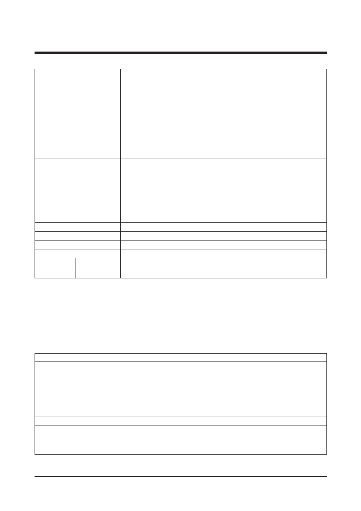
2272 : 2272X1704 2048 : 2048X1536
Image Size 1600 : 1600X1200 1024 : 1024X768
640 : 640X480
2272 : Super fine (10) Fine (20) Normal (33)
2048 : Super fine (13) Fine (27) Normal (42)
1600 : Super fine (17) Fine (37) Normal (50)
1024 : Super fine (38) Fine (78) Normal (113)
640 : Super fine (81) Fine (145) Normal (234)
* These figures are measured under Samsung’s standard conditions and may
vary depending on shooting conditions and camera settings.
Type Single image / Thumbnails / Slide show/ Movie clip
Editing Rotation, Trimming, Resizing
Interface Digital output connector: USB 1.1
Primary battery : 2 x AA alkaline, Lithium, Ni-Mn,
Ni-Zn, 1X CR-V3
Rechargeable battery : 2 x AA Ni-MH,
Ni-Cd / 1 x I-Pack (SBP-1303)
Dimensions (WxHxD) 96.5 x 52.5 x 30.5 mm
Weight Approx. 90g (without batteries and card)
Operating Temperature 0 ~40 °C
Operating Humidity 5 ~85%
Storage Driver (Windows98/98SE)
Digimax Viewer, Arcsoft PhotoImpression
5
ⅠⅠ.. SSPPEECCIIFFIICCAATTIIOONN
Capacity
(16MB)
Storage
Image Play
Power Source
Software
Camera Driver
Application
For Windows For Macintosh
PC with processor better than MMX Power Mac G3 or later
Pentium 233MHz (XP : Pentium II 300MHz)
Windows 98/98SE/2000/ME/XP Mac OS 9.2~10.3
Minimum 32MB RAM (XP : 128MB) Minimum 64MB RAM
140MB of available hard-disk space 110MB of available hard-disk space
USB port USB port
CD-ROM drive CD-ROM drive
800x600 pixels, 16-bit colour display QuickTime 6.01 or later for Movie Clip
compatible monitor (24-bit colour display
recommended)
2. SYSTEM REQUIREMENTS
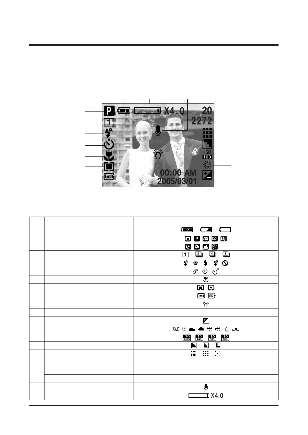
■ Recording Mode
6
ⅠⅠ.. SSPPEECCIIFFIICCAATTIIOONN
No. Description Icons
1 Battery
3 Continuous shot
4 Flash
5 Self-timer
6 Macro
7 Metering
8 Card inserted indicator
9 Camera shake warning
10 Date/Time 2005/03/01 00:00AM
11 Exposure compensation
12 White Balance
13 ISO
14 Sharpness
15 Image qualty
16 Image size 2272, 2048, 1600, 1024, 640
Number of available shots remaining 20
Remaining time(Movie clip/Voice recording) 00:01:11/ 00:25:50
18 Voice memo
19 Digital Zoom rate
17
②
③
④
⑤
⑥
⑦
⑧
⑪
⑫
⑬
⑭
⑮
⒃
⒔
⑩
⑨
⒖
⒕
①
Recording mode
2
3. TFT LCD PANEL MARK
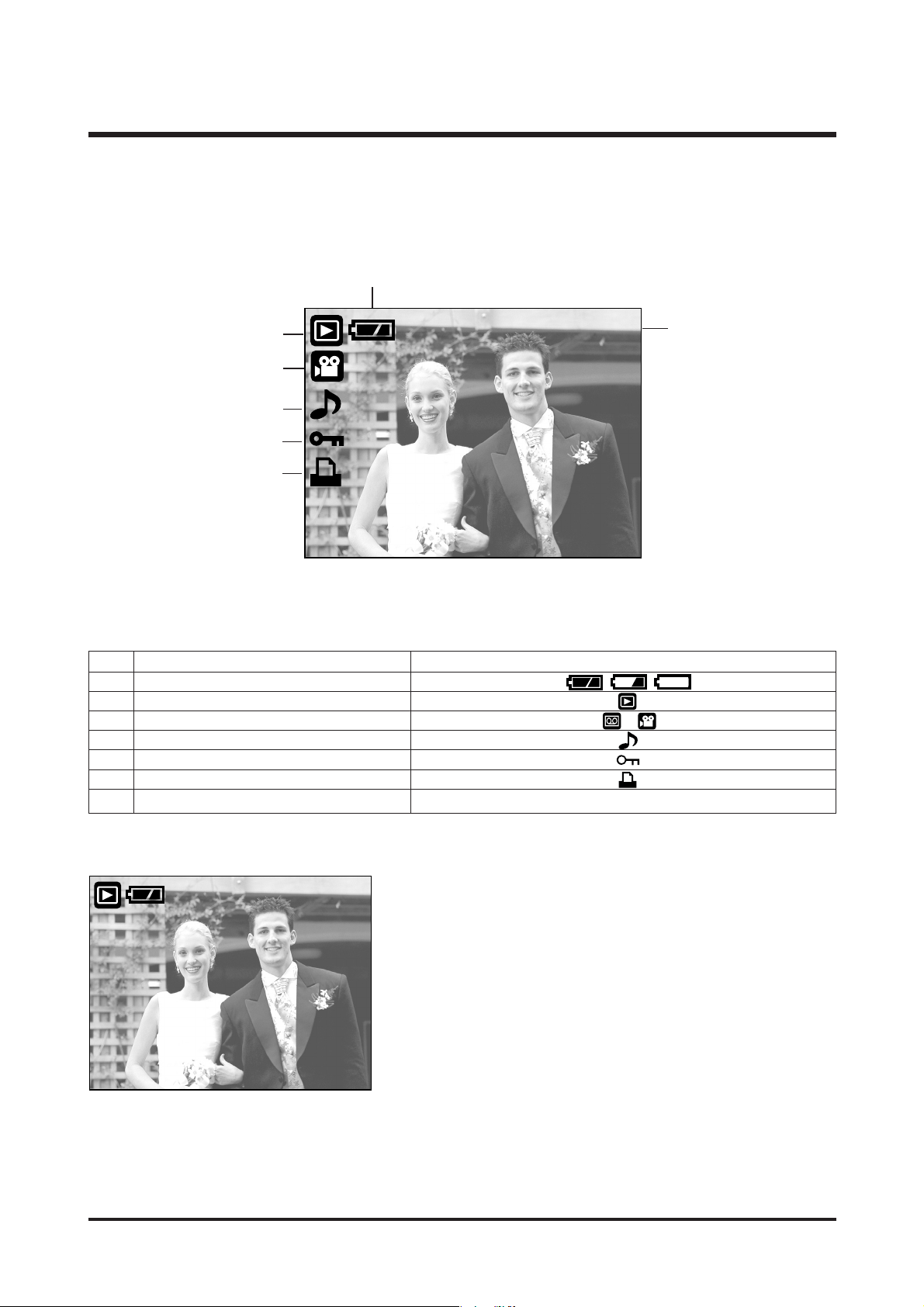
■ Play Mode
NO. Description Icons
1 Battery
2 Play mode
3 File Type
4 Voice memo
5 Protect indicator
6 DPOF indicator
7 Stored image number 100-0009
7
ⅠⅠ.. SSPPEECCIIFFIICCAATTIIOONN
100-0009
①
⑦
②
③
④
⑤
⑥
SIZE : 2272X1704 Size
AV : F3.5 Aperture value
TV : 1/18 Shutter speed
FLASH : OFF Whether or not the
flash is used.
DATE : 2005/03/01 Recording date
100-0009
SIZE : 2272X1704
AV : F3.5
TV : 1/18
FLASH : OFF
DATE : 2005/03/01
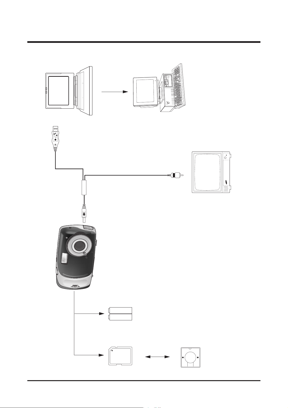
4. Connection Diagram
8
ⅠⅠ.. SSPPEECCIIFFIICCAATTIIOONN
USB Cable
Lap top
IBM / MAC
Video Cable
TV Monitor
SNB-2312
SD Card
Card Reader
9
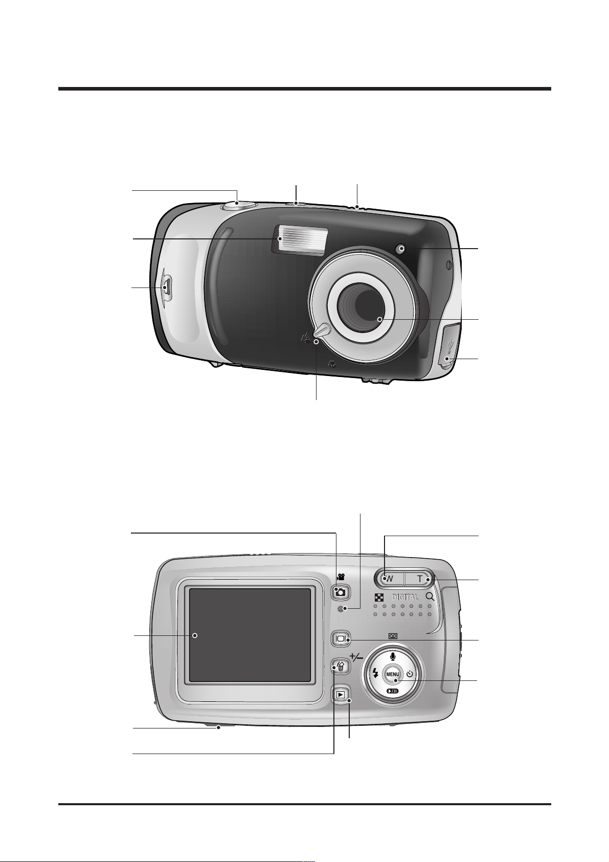
ⅠⅠ.. SSPPEECCIIFFIICCAATTIIOONN
Tripod socket
Focus ring
Flash
Strap eyelet
LCD monitor
Shutter button
Mode button
Power button
Play mode button
Microphone
Self-timer lamp
Lens
5-function button
LCD button
Zoom T button
(Digital zoom)
Camera status lamp
USB
connection port
+/-, DELETE button
Zoom W button
(Thumbnail)
5. Identification of Features
10
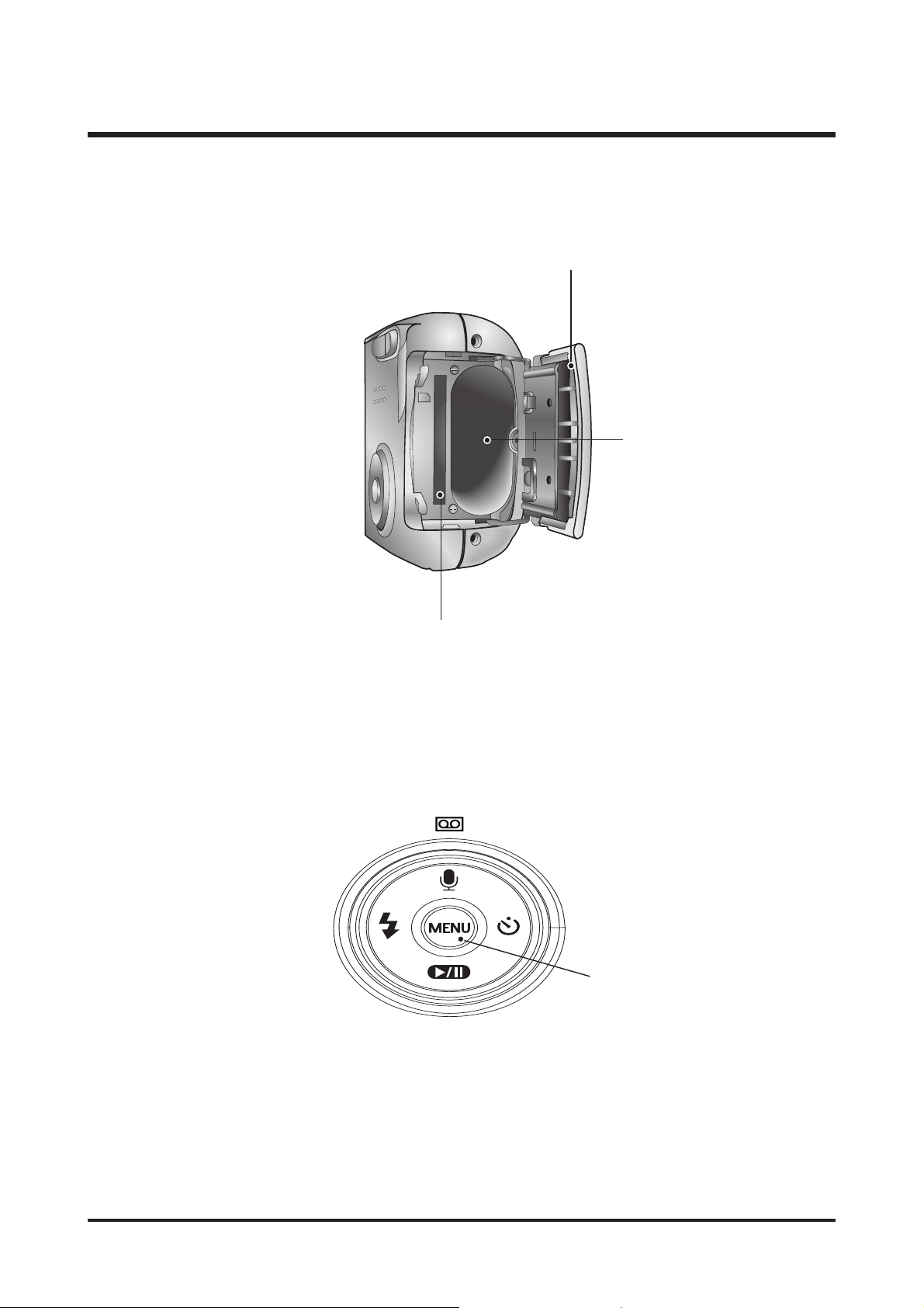
ⅠⅠ.. SSPPEECCIIFFIICCAATTIIOONN
FLASH/ LEFT
button
MENU/
OK button
PLAY&PAUSE/ DOWN button
SELF-TIMER/
RIGHT button
Voice Recording/
Voice memo/ UP button
Memory card slot
Battery chamber
Battery chamber cover
※ The OK button written in this manual means the MENU button.
11
ⅡⅡ.. IINNSSTTAALLLLAATTIIOONN
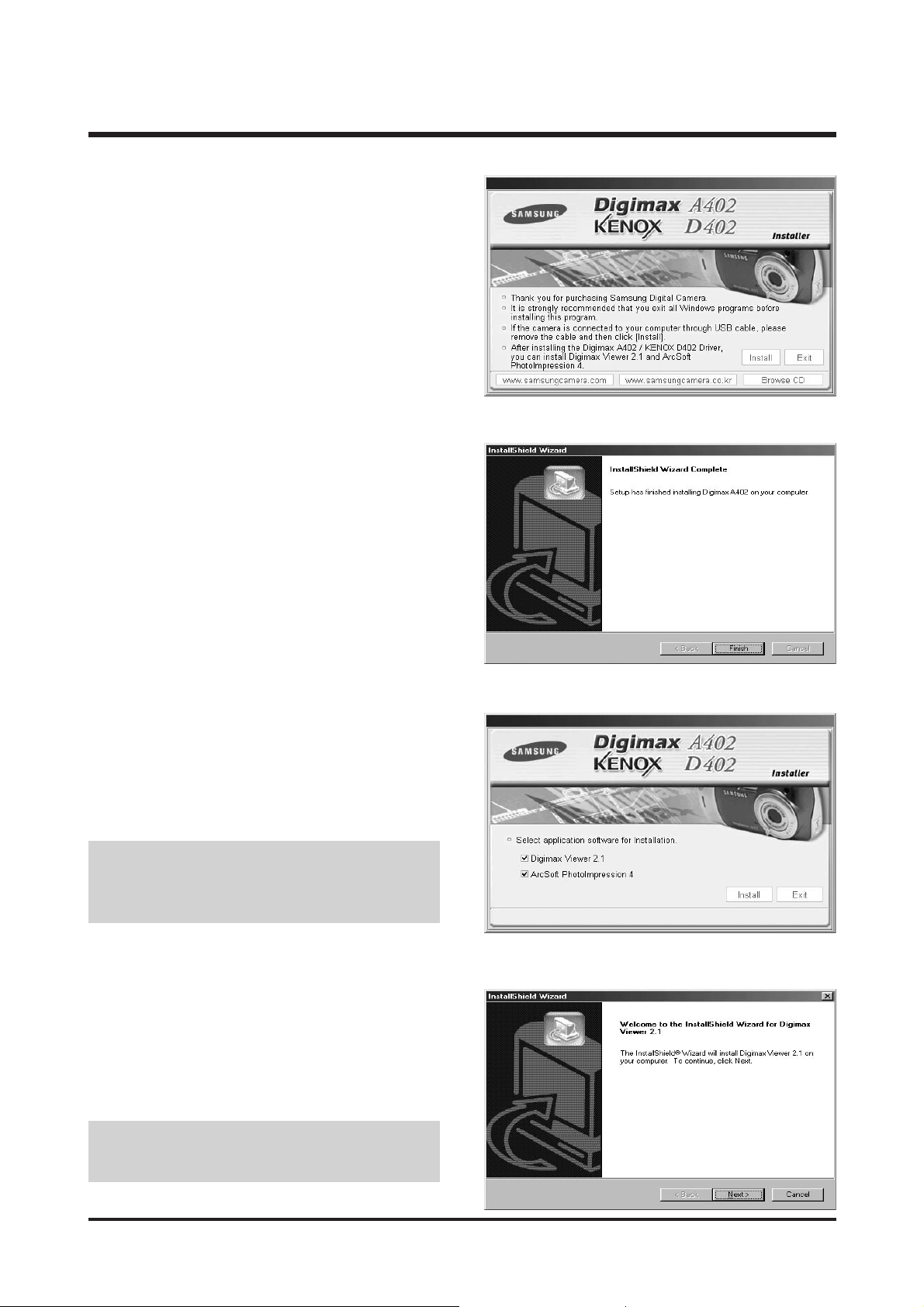
1. Click the [Install] menu in the Autorun frame.
The camera driver is installed automatically.
2. Camera driver installation is complete.
Click the [Finish] button.
3. A window for which you can select application
software will be displayed. Select the application
program and click the [Install] button. Refer to page
88 for more information about the application
program.
4. Install Digimax Viewer.
Click [Next >] button.
● If you select [Exit] at the step 3, the
application program installation will be
cancelled.
● If you select [Cancel] at step 4, a window for
installing PhotoImpression will be displayed.
12
ⅡⅡ.. IINNSSTTAALLLLAATTIIOONN
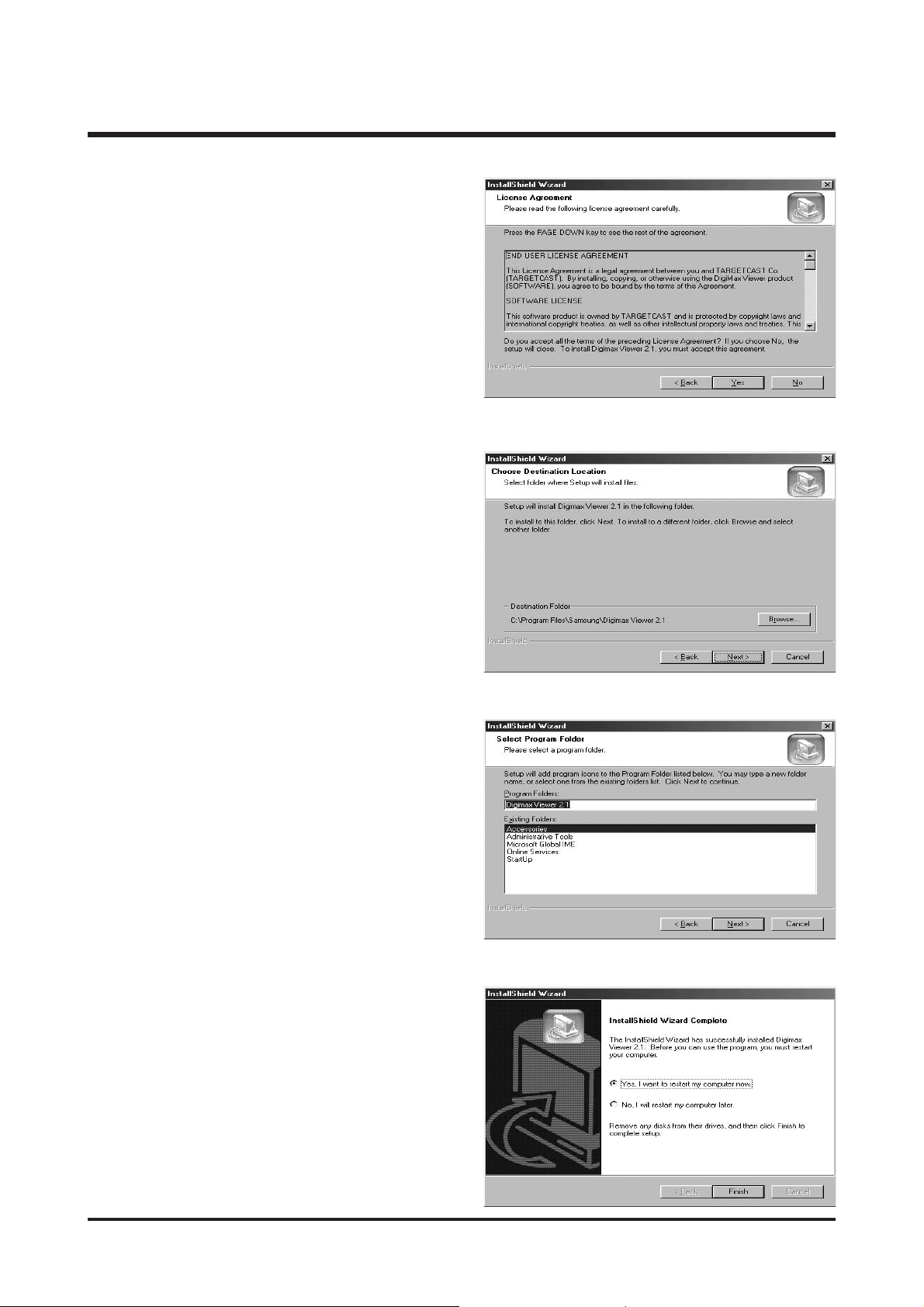
8. Digimax Viewer installation is successfully
completed. Click the [Finish] button to install
PhotoImpression. The system will not reboot even if
the [Yes, I want to restart the computer now] option
is selected.
* The frame 8 may not appear according to the
system requirements.
7. A window will open, asking you to choose a folder
to which program icons will be added.
Click [Next >] button. If you want to add the
program icons to a different folder, choose another
folder, and then click [Next >] button.
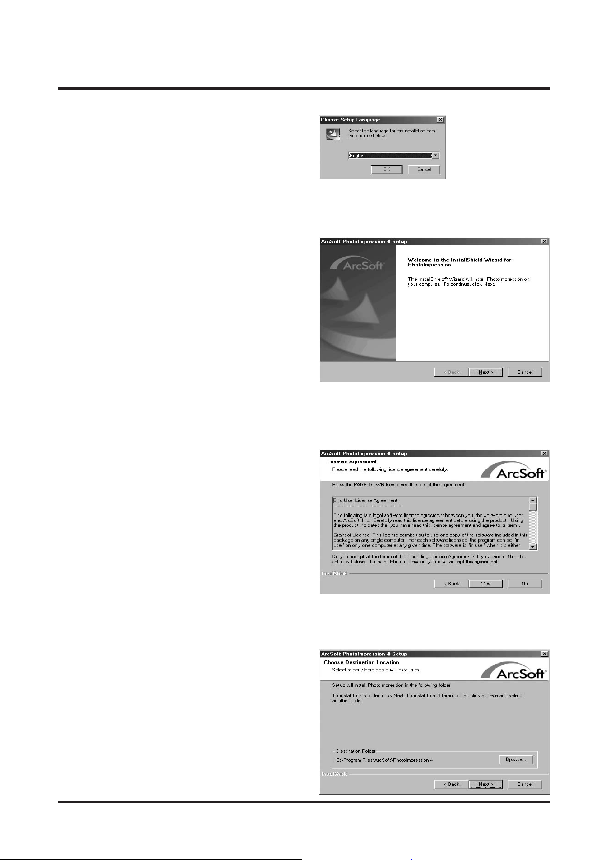
5. The Software License Agreement window will be
displayed. If you agree to this, click [Yes], the
window will then move to the next step.
If you disagree, click [No] and the installation
program will be cancelled.
6. A destination selection window will open.
Click [Next >]. To copy to the files to another folder,
click [Browse...] and choose a folder you want.
13
ⅡⅡ.. IINNSSTTAALLLLAATTIIOONN
9. The PhotoImpression installation window will be
displayed as shown alongside.
Click the [OK] button.
10. A Welcome window will be displayed.
Click the [Next >] button.
12. A destination selection window will open.
Click [Next >]. To copy to the files to another
folder, click [Browse...] and choose a folder you
want.
11. The Software License Agreement window will be
displayed. If you agree to this, click [Yes], the
window will then move to the next step.
If you disagree, click [No] and the installation
program will be cancelled.
14
ⅡⅡ.. IINNSSTTAALLLLAATTIIOONN
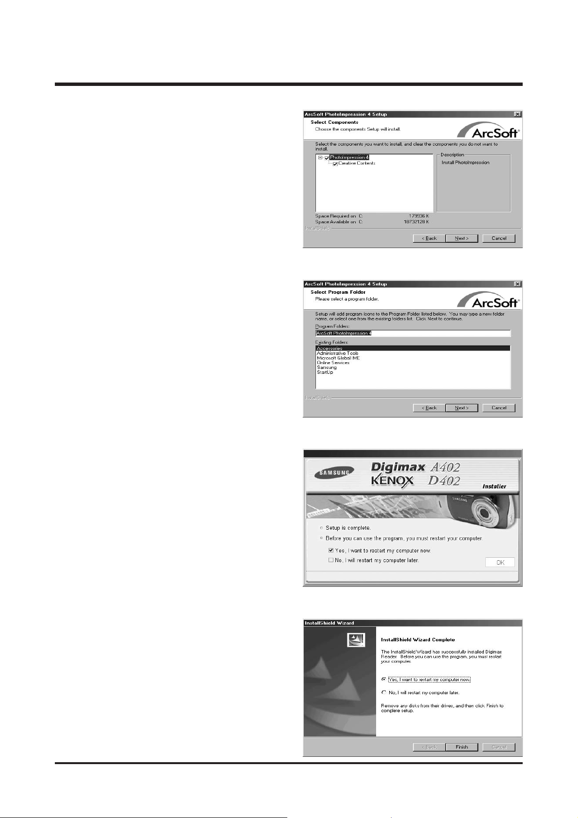
15. Installation is complete. To apply changes, you
must restart the computer.
Select [Yes, I want to restart my computer now],
and then click [OK].
* The frame 15 may be displayed according to the
system requirements.
Click the [Finish] button to restart the computer.
13. The [Select Components] window will appear.
Click [Next >] button.
14. A window will open, asking you to choose a folder
to which program icons will be added.
Click [Next >] button. If you want to add the
program icons to a different folder, choose another
folder, and then click [Next >] button.
15
ⅡⅡ.. IINNSSTTAALLLLAATTIIOONN
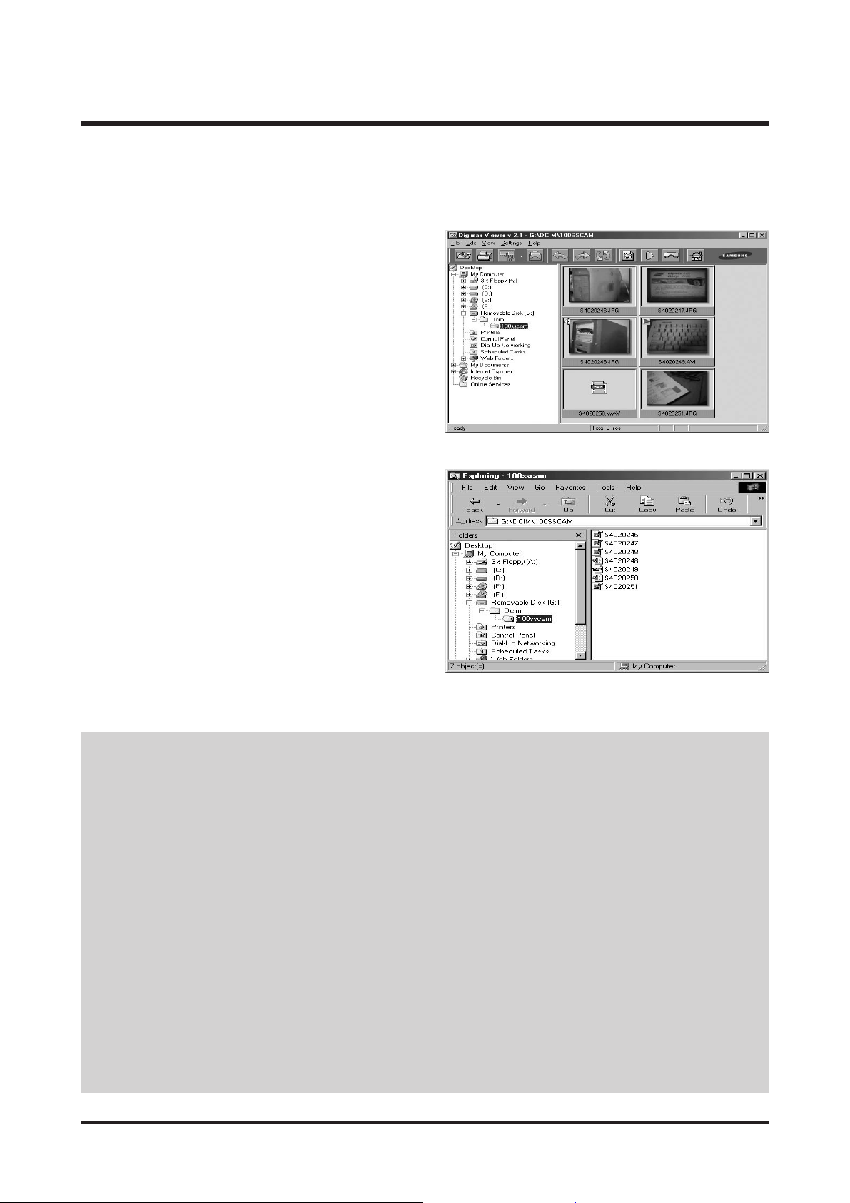
16. After restarting the computer, connect the PC to the camera with the USB cable.
17. Turn the camera power on. [Found New
Hardware Wizard] will open and the computer will
recognise the camera.
* If you have ever installed an image viewer
program or your OS is Windows XP, an image
viewer program will open. If the image viewer
program opens, the camera driver was setup
successfully.
18. If you can see [Removable Disk] under [My
computer], the camera driver installation was
successful. Now you can transfer image files from
the camera to PC via the USB cable.
● If you have installed the camera driver, [Found New Hardware Wizard] may not open.
● On a Windows 98 or 98 SE system, the Found New Hardware Wizard dialog box opens and a window asking
you to select a driver file may appear. In this case, specify "USB Driver" in the CD supplied.
● Before connecting the camera to the PC, You should first install the camera driver.
● After installing the camera driver, you have to restart your PC.
● If you connect the camera to the PC before installing the camera driver, the [Found New Hardware Wizard] will
open.
In this case, cancel the [Found New Hardware Wizard] and disconnect the camera. Install the camera driver and
connect the camera to the PC again.
● Should the computer not find the camera driver after installation, please try one or more of the following
measures.
1. Delete the camera driver , and re-install the driver.
2. Refer to FAQ to check for a possible solution to the problem.
3. If your PC’s central processing unit is VIA chip (This is shown in the USB Host Controller), download the patch
file from the Samsung Camera web page. (http://www.samsungcamera.com)
16
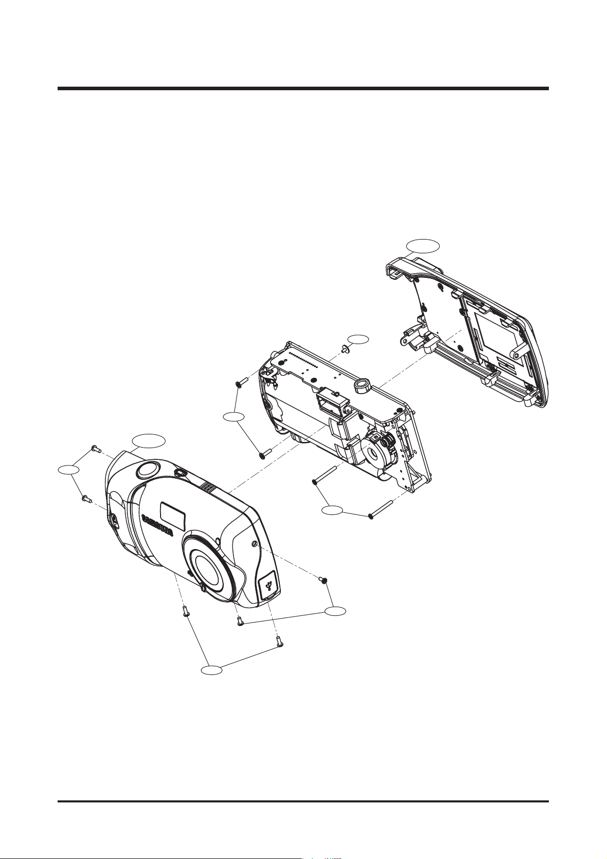
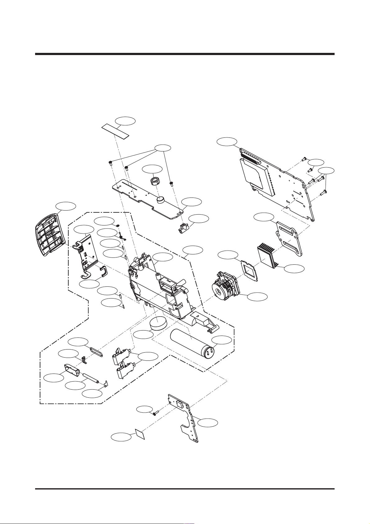
ⅢⅢ.. EEXXPPLLOODDEEDD VVIIEEWW AANNDD PPAARRTT LLIISSTT
1. MAIN ASSEMBLY
1-7
1-2
1-4
1-1
3
1-
1-6
1-5
1-3

17
ⅢⅢ.. EEXXPPLLOODDEEDD VVIIEEWW AANNDD PPAARRTT LLIISSTT
▶▶
PARTS LIST
1-1 Q9007230001A Front Cover Asscmbly-Blue(KENOX D402) 1
Q9007230701A Front Cover Asscmbly-Silver(KENOX D402) 1
Q9007230801A Front Cover Asscmbly-Red(KENOX D402) 1
Q9007231101A Front Cover Asscmbly-Blue(DIGIMAX A402) 1
Q9007231201A Front Cover Asscmbly-Silver(DIGIMAX A402) 1
Q9007231301A Front Cover Asscmbly-Red(DIGIMAX A402) 1
1-2 Q9007230101A Back Cover Asscmbly-Blue 1
Q9007230901A Back Cover Asscmbly-Silver 1
Q9007231001A Back Cover Asscmbly-Red 1
1-3 Q6009002901A Screw 4
1-4 Q6003045901A Screw 2
1-5 Q6009003001A Screw 2
1-6 Q6009003101A Screw 2
1-7 Q6009003201A Screw 1
Fig.No Parts No. Parts Name Q’ty Remarks
18
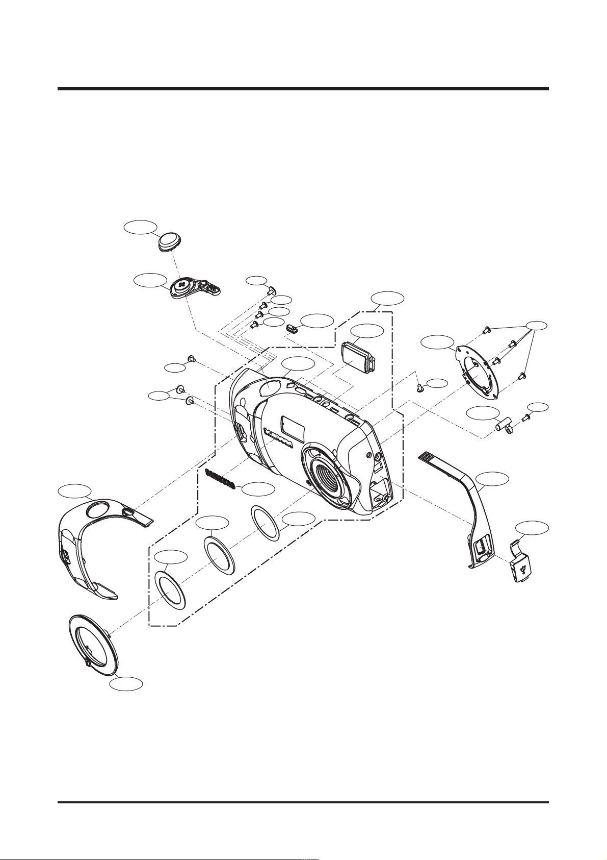
ⅢⅢ.. EEXXPPLLOODDEEDD VVIIEEWW AANNDD PPAARRTT LLIISSTT
2. BODY ASSEMBLY
2-26
2-15
2-11
2-12
2-3
2-4
2-2
2-1
2-2
2-1
2-17
2-24
2-7
2-16
2-18
2-20
2-23
2-24
2-25
2-30
2-28
2-29
2-19
2-13
2-5
2-6
2-8
2-10
2-9
2-14
2-21
2-24
2-22
2-27

19
ⅢⅢ.. EEXXPPLLOODDEEDD VVIIEEWW AANNDD PPAARRTT LLIISSTT
▶▶
PARTS LIST
2-1 Q7009000301A Battery Stop Axle 1
2-2 Q7009000101A Battery Cover Axle 1
2-3 Q6107064801A Battery Spring Washer 1
2-4 Q6107064901A Battery Cover Spring 1
2-5 Q7009000201A Trigger Contact 1
2-6 Q7309044801A Flash Rubber 1
2-7 Q7204023101A Battery Compartmant 1
2-8 Q0611004101A Flash Tube 1
2-9 Q2401009101A Photo Flash CAP 1
2-10 Q3002001401A Piezo Buzzer 1
2-11 Q7001004901A Battery Contact Lower 1
2-12 Q7209001401A Battery Stopper 1
2-13 Q0607000901A Flash Retlector 1
2-14 Q7101000601A Battery Contact Upper 2
2-15 Q7217356701A Ass'y Battery Cover-Blue 1
Q7204023301A Ass'y Battery Cover-Silver 1
Q7204023401A Ass'y Battery Cover-Red 1
2-16 Q9008086401A Ass'y Shutter 1
2-17 Q7309044501A MIC Rub Contact 1
2-18 Q7204023201A PCB FIX BOSS 1
2-19 Q9002140101A Lens Assembly 1
2-20 Q9001103201A Battery Compartmant Assmbly 1
2-21 Q7001005001A Tube Contact 1
2-22 Q9008086501A Ass'y USB 1
2-23 Q9008086601A Ass'y Main 1
2-24 Q6003042301A Screw 6
2-25 Q6003039401A Screw 3
2-26 Q7409190801A Flash Mylar 1
2-27 Q7409190901A USB Mylar 1
2-28 Q7309046501A CCD Rubber 1
2-29 Q0604005201A CCD Sensor 1
2-30 Q7101000701A CCD Plate 1
Fig.No Parts No. Parts Name Q’ty Remarks
20
ⅢⅢ.. EEXXPPLLOODDEEDD VVIIEEWW AANNDD PPAARRTT LLIISSTT
3. FRONT COVER ASSEMBLY
3-8
3-5
3-7
3-19
3-16
3-2
3-3
3-17
3-6
3-16
3-16
3-16
3-10
3-4
3-9
3-15
3-20
3-14
3-16
3-13
3-12
3-16
3-18
3-11
3-1

21
ⅢⅢ.. EEXXPPLLOODDEEDD VVIIEEWW AANNDD PPAARRTT LLIISSTT
3-1 Q7204022801A Focus Ring 1
3-2 Q7409190401A Lens Panel 1
3-3 Q7209000601A Lens Cover 1
3-4 Q7409190501A Lens Plate Tape 1
3-5 Q7217356301A Ass'y Middle Cover 1
3-6 Q7217303501A Samsung Plate 1
3-7 Q7204022901A Power Release Button Arm 1
3-8 Q7209000701A Ass'y Release Button 1
3-9 Q7209000801A Ass'y Power Button 1
3-10 Q7217356401A Front Cover-Blue(KENOX D402) 1
Q7217357101A Front Cover-Silver(KENOX D402) 1
Q7217357201A Front Cover-Red(KENOX D402) 1
Q7217357301A Front Cover-Blue(DIGIMAX A402) 1
Q7217357401A Front Cover-Silver(DIGIMAX A402) 1
Q7217357501A Front Cover-Red(DIGIMAX A402) 1
3-11 Q7309046301A USB Cover TPU 1
3-12 Q7217356501A Ass'y Middle Cover-2 1
3-13 Q7209000901A Front Led Guide 1
3-14 Q7101000501A Lens Cover Sheet Metal 1
3-15 Q7217356601A Flash Cover 1
3-16 Q6003031501A Screw 11
3-17 Q6009003301A Screw 1
3-18 Q6003045901A Screw 1
3-19 Q6003031301A Screw 2
3-20 Q9007231401A Front Cover SUB Asscmbly-Blue(KENOX D402) 1
Q9007231501A Front Cover SUB Asscmbly-Silver(KENOX D402) 1
Q9007231601A Front Cover SUB Asscmbly-Red(KENOX D402) 1
Q9007231701A Front Cover SUB Asscmbly-Blue(DIGIMAX A402) 1
Q9007231801A Front Cover SUB Asscmbly-Silver(DIGIMAX A402) 1
Q9007231901A Front Cover SUB Asscmbly-Red(DIGIMAX A402) 1
Fig.No Parts No. Parts Name Q’ty Remarks
▶▶
PARTS LIST
22
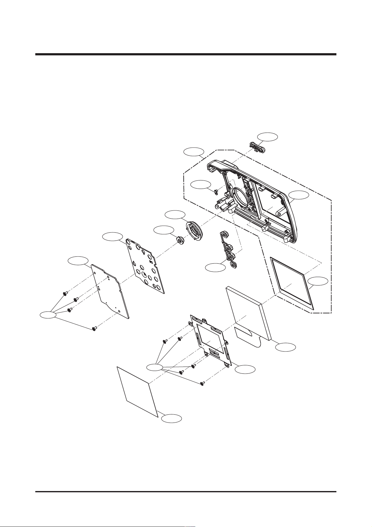
ⅢⅢ.. EEXXPPLLOODDEEDD VVIIEEWW AANNDD PPAARRTT LLIISSTT
4. BACK COVER ASSEMBLY
4-12
4-1
4-11
4-10
4-5
4-13
4-2
4-3
4-14
4-4
4-6
4-9
4-8
4-7
4-15

23
ⅢⅢ.. EEXXPPLLOODDEEDD VVIIEEWW AANNDD PPAARRTT LLIISSTT
4-1 Q9007232001A Back Cover SUB Assnbly-Blue 1
Q9007232101A Back Cover SUB Assnbly-Silver 1
Q9007232201A Back Cover SUB Assnbly-Red 1
4-2 Q9008086301A Key Assembly 1
4-3 Q7309046401A Key Pad Rubber 1
4-4 Q7209001001A Ass'y OK Button 1
4-5 Q7209001101A Ass'y Direction Button 1
4-6 Q7204023001A Ass'y Button 1
4-7 Q7001004801A TFT Holder 1
4-8 Q0704011501A TFT LCD 1
4-9 Q7409190601A TFT Sponge 1
4-10 Q7217356801A Back Cover-Blue 1
Q7217356901A Back Cover-Silver 1
Q7217357001A Back Cover-Red 1
4-11 Q7209001201A Led Guide Back 1
4-12 Q7209001301A Ass'y Zomm Button 1
4-13 Q6003031501A Screw 4
4-14 Q6009003401A Screw 5
4-15 Q7409190701A TFT Mylar 1
Fig.No Parts No. Parts Name Q’ty Remarks
▶▶
PARTS LIST
24
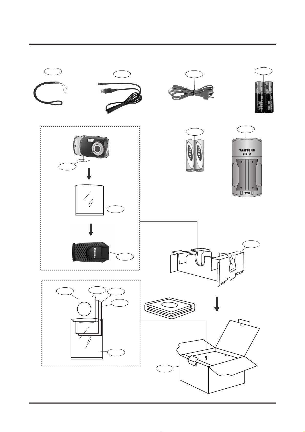
ⅢⅢ.. EEXXPPLLOODDEEDD VVIIEEWW AANNDD PPAARRTT LLIISSTT
5. PACKING ITEM
5-10
5-13
5-11 5-14
5-1
5-15
5-9
5-16
5-12
5-5
5-3
5-4
5-6
5-7
5-2
5-8

25
ⅢⅢ.. EEXXPPLLOODDEEDD VVIIEEWW AANNDD PPAARRTT LLIISSTT
5-1 QP960210101A PE BAG (FOR CAMERA) 1
5-2 Q6909011601A PE BAG (FOR ACCESSORY) 1
5-3 Q6901208301A INNER PAD_D Digimax A402_KOR/EXP 1
5-4 Q6904026401A POUCH_Digimax A402 (SAMSUNG) 1
5-5 Q6806254401A Q/GUIDE_KENOX D402_KOR 1
Q6806254501A Q/GUIDE_Digimax A402_ENG 1
Q6806254601A Q/GUIDE_Digimax A402_GER 1
Q6806254701A Q/GUIDE_Digimax A402_FRA 1
Q6806254801A Q/GUIDE_Digimax A402_SPA 1
Q6806254901A Q/GUIDE_Digimax A402_ITA 1
Q6806255001A Q/GUIDE_Digimax A402_TUR 1
Q6806255101A Q/GUIDE_Digimax A402_DUT 1
Q6806255201A Q/GUIDE_Digimax A402_POR 1
Q6806255301A Q/GUIDE_Digimax A402_SWE 1
Q6806255401A Q/GUIDE_Digimax A402_DEN 1
Q6806255501A Q/GUIDE_Digimax A402_FIN 1
Q6806255601A Q/GUIDE_Digimax A402_RUS 1
Q6806255701A Q/GUIDE_Digimax A402_CHI(S) 1
Q6806255801A Q/GUIDE_Digimax A402_CHI(T) 1
5-6 Q6806255901A U/MANUAL_KENOX D402_KOR 1
Q6806256001A U/MANUAL_Digimax A402_ENG 1
Q6806256101A U/MANUAL_Digimax A402_GER 1
Q6806256201A U/MANUAL_Digimax A402_FRA 1
Q6806256301A U/MANUAL_Digimax A402_SPA 1
Q6806256401A U/MANUAL_Digimax A402_ITA 1
Q6806256501A U/MANUAL_Digimax A402_TUR 1
Q6806256601A U/MANUAL_Digimax A402_DUT 1
Q6806256701A U/MANUAL_Digimax A402_POR 1
Q6806256801A U/MANUAL_Digimax A402_SWE 1
Q6806256901A U/MANUAL_Digimax A402_DEN 1
Q6806257001A U/MANUAL_Digimax A402_FIN 1
Q6806257101A U/MANUAL_Digimax A402_RUS 1
Q6806257201A U/MANUAL_Digimax A402_CHI(S) 1
Q6806257301A U/MANUAL_Digimax A402_CHI(T) 1
5-7 Q6807002601F WARRANTY CARD_KOREA 1
Q6807003003U WARRANTY CARD_EXP 1
Q6807010903C WARRANTY CARD_RUS(3 YEARS) 1
Q6807011301B WARRANTY CARD_TSOE(CHINA) 1
5-8 Q6901208401A G/T BOX_KENOX D402_KOR 1
Q6901208501A G/T BOX_Digimax A402_EXP/AUS 1
Q6901208601A G/T BOX_Digimax A402_USA/CAN 1
5-9 Q4301001801A "ALKALINE (1.5V, AA) 2EA - DURACEL ULTRA" 1
Fig.No Parts No. Parts Name Q’ty Remarks
▶▶
PARTS LIST

26
ⅢⅢ.. EEXXPPLLOODDEEDD VVIIEEWW AANNDD PPAARRTT LLIISSTT
5-10 Q7409121701A STRAP_D301/D202/D401/U-CA 501/D402_KOR/EXP 1
5-11 Q3801002801A USB CABLE_D200/201/300/301/202 1
5-12 Q4609011001A
DRIVER + Digimax Viewer 2.1+ Arcsoft PhotoImpression 4.0
1
5-13 Q7409185401A FCC LABEL_Digimax A402_EXP (MADE IN CHINA) 1
Q7409185501A FCC LABEL_Digimax A402_EXP (MADE BY SAMSUNG) 1
5-14 Q3801003001A AC CODE CABLE_KOR-D1 1
Q3801003201A AC CODE CABLE_EXP-D1 1
Q3801003101A AC CODE CABLE_USA-D1 1
Q3801001001A AC CODE CABLE_UK-DSC220SE 1
Q3801003401B AC CODE CABLE_AUS-D1 1
5-15 Q4301003101A "Ni-MH BATTERY SNB-2312 (1.2V, AA) - SAMSUNG" 1
5-16 Q4301003001A Ni-MH CHARGER SBC-N1 1
Fig.No Parts No. Parts Name Q’ty Remarks
27
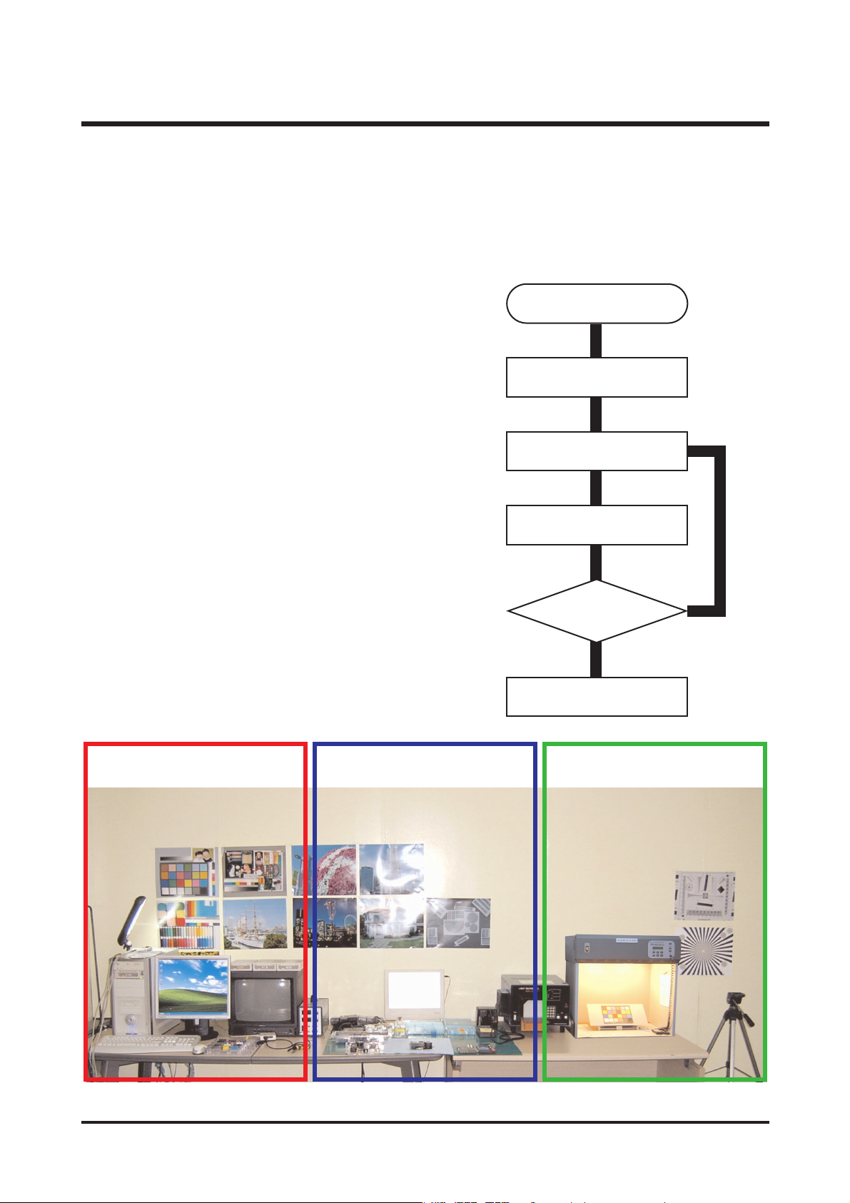
ⅣⅣ.. AADDJJUUSSTTMMEENNTT
To take a digital camera service(Repair, Tuning and Checking), the following equipments have to be
arranged.
The sequences for the camera service are as shown
alongside.
1. Receiving the camera
When receiving a camera, check whether the accessories
are included or not and ask the customer exact problems.
2. Checking the camera
Checking the camera with priority given to the exact
problems to find overall malfunctions.
3. Repairing the camera
Repair the camera malfunctions found at the step 2.
4. Inspection
After repairing the camera, inspect all of the camera
functions.
1. Digital camera service
※ The illustrations may be different from the real display in accordance with the camera model.
1. Checking the camera and
Inspection
2. Repairing the camera 3. Tuning
Receiving the camera
Checking the camera
Repairing the camera
Tuning
Inspection
Finish