

SAMSUNG DIGIMAX A400 SERVICE INFORMATION

2
CONTENTS
ⅠⅠ
.. SSPPEECCIIFFIICCAATTIIOONN
1. CAMERA SPECIFICATION ……………………………………………………………………………………… 4
2. SYSTEM REQUIREMENTS ……………………………………………………………………………………… 5
3. TFT LCD PANEL MARK ………………………………………………………………………………………… 6
4. CONNECTION DIAGRAM ………………………………………………………………………………………… 8
5. IDENTIFICATION OF FEATURES………………………………………………………………………………… 9
ⅡⅡ
.. IINNSSTTAALLLLAATTIIOONN && FFAAQQ
………………………………………………………………………………… 11
ⅢⅢ.. EEXXPPLLOODDEEDD VVIIEEWW AANNDD PPAARRTTSS LLIISSTT
1. MAIN ASSEMBLY…………………………………………………………………………………………………18
2. BODY COVER ASSEMBLY ………………………………………………………………………………………20
3. BARREL ASSEMBLY ……………………………………………………………………………………………22
4. FRPMT COVER ASSEMBLY …………………………………………………………………………………… 24
5. BACK COVER ASSEMBLY ………………………………………………………………………………………26
6. PACKING ITEM……………………………………………………………………………………………………28
7. INITIAL PARTS LIST ………………………………………………………………………………………………
ⅣⅣ.. AADDJJUUSSTTMMEENNTT
1. Digital Camera Service …………………………………………………………………………………………31
2. How to check the FIRMWARE VERSION………………………………………………………………………37
3. How to update the FIRMWARE UPGRADE ……………………………………………………………………38
4. ADJUSTMENT ……………………………………………………………………………………………………40
ⅤⅤ.. PPAATTTTEERRNN DDIIAAGGRRAAMM
1. PARTS ARRANGEMENT FOR EACH PCB ASS’Y
1) MAIN_TOP…………………………………………………………………………………………………48
2) MAIN_BOTTOM……………………………………………………………………………………………49
3) KEY_TOP …………………………………………………………………………………………………50
4) KEY_BOTTOM ……………………………………………………………………………………………51
5) CCD_TOP …………………………………………………………………………………………………52
6) CCD_BOTTOM ……………………………………………………………………………………………53
7) SHUTTER……………………………………………………………………………………………………54
ⅥⅥ
.. CCUURRCCUUIITT DDIIAAGGRRAAMM
1. BLOCK DIAGRAM………………………………………………………………………………………………55
2. CURCUIT DIAGRAM
1) TOP VIEW …………………………………………………………………………………………………56
2) TFT LCD ……………………………………………………………………………………………………57
3) CONNECTOR ………………………………………………………………………………………………58
4) SPCA536 DSP………………………………………………………………………………………………59
5) IMAGE SENSOR-PERIPERIC CIRCUIT ……………………………………………………………………60
6) IMAGE SENSOR-MOTOR DRIVER ………………………………………………………………………61
7) SDRAM/TRAP/EEPROM …………………………………………………………………………………62
8) FLASHROM/NANDFLASH/SD ……………………………………………………………………………63
9) USB 1.1/MIC/TVOUT/BUZZE ……………………………………………………………………………64
10) POWER MODULE-MAX1566 ……………………………………………………………………………65
11) INTERFACE IO ……………………………………………………………………………………………66
12) POWER MODULE-STROBE FLASH ……………………………………………………………………67
13) POER SOURCE/RESET/LED ……………………………………………………………………………68
14) IMAGE SENSOR FPC-MN39482…………………………………………………………………………69
15) MICROPHONE/SHUTTER/POWER ON/FULL COLOR LED ……………………………………………70

3
ⅦⅦ
.. TTRROOUUBBLLEESSHHOOOOTTIINNGG
1. Check List for Repairing ……………………………………………………………………………………71
2. ………………………………………………………………………………………………………………72
3. How to ASSEMBLY ……………………………………………………………………………………………80
ⅧⅧ.. SSEERRVVIICCEE IINNFFOORRMMAATTIIOONN
…………………………………………………………………………………86

4
ⅠⅠ.. SSPPEECCIIFFIICCAATTIIOONN
11.. CCAAMMEERRAA SSPPEECCIIFFIICCAATTIIOONN
Type 1/2.5" CCD
Effective Pixels Approx. 4.0 Mega –pixel
Total Pixels Approx. 4.2 Mega –pixel
SHD lens f= 6.2 ~ 17.4mm
(35mm equivalent : 37 ~ 104mm)
F No. F 2.9 ~ F4.8
Still Image mode: 1.0X ~ 4.0X
Play mode: 1.0X ~ 7.0X(depends on image size)
LCD Montor 2.0" colour TFT LCD
Type TTL Auto Focus
Normal: 80cm ~ infinity
Macro: 5cm ~ 80cm(Wide), 39cm ~ 80cm(Tele)
Type Mechanical and Electronic shutter
Speed 2 ~ 1/1,000sec. (8 ~ 1/1,000sec. in Night Scene mode)
Program AE,
Metering: Multi, Spot
Compensation
±
2.0EV (0.5EV steps)
ISO Equivalent Auto, 100, 200, 400
Modes Auto, Auto & Red-eye reduction, Fill-in flash, Slow sync, Flash off
Range Wide: 0.3 ~ 3.0m, Tele: 0.3 ~ 2.0m
Recharging time Approx. 5 ~ 7sec.
Sharpness Soft, Normal, Vivid
Effect Normal, B&W, Sepia, RGB
White Balance Auto, Daylight, Cloudy, Sunset, Fluorescent(H), Fluorescent(L), Tungsten, Custom
Photo Frame 9 Frames
Voice Recording (Max. 1 hour)
Voice Memo in Still Image (max 10 sec.)
Date Imprinting Date & Time, Date, OFF (User selectable)
Modes: Auto, Program, Scene
Scene: Night, Portrait, Landscape, Text, Fireworks
Shooting: Single, Continuous
With audio (Recording time: memory capacity dependent)
Size : 640X480, 320x240 ( 24fps/ 15fps)
Self-timer 10 sec, 2sec, Double self (10/2sec.)
Internal memory : 16MB flash memory
External memory (optional) : SD memory card/ MMC
(Up to 512MB guaranteed)
Still Image: JPEG (DCF), EXIF 2.2, DPOF 1.1, PictBridge 1.0
Movie Clip: AVI (MJPEG), Voice : WAV
Image
Sensor
Lens
Focal Length
Digital Zoom
Stiil Image
Voice Recording
Flash
Exposure
Control
Shutter
Range
Focusing
Movie Clijp
Media
File Format
Shooting
Storage
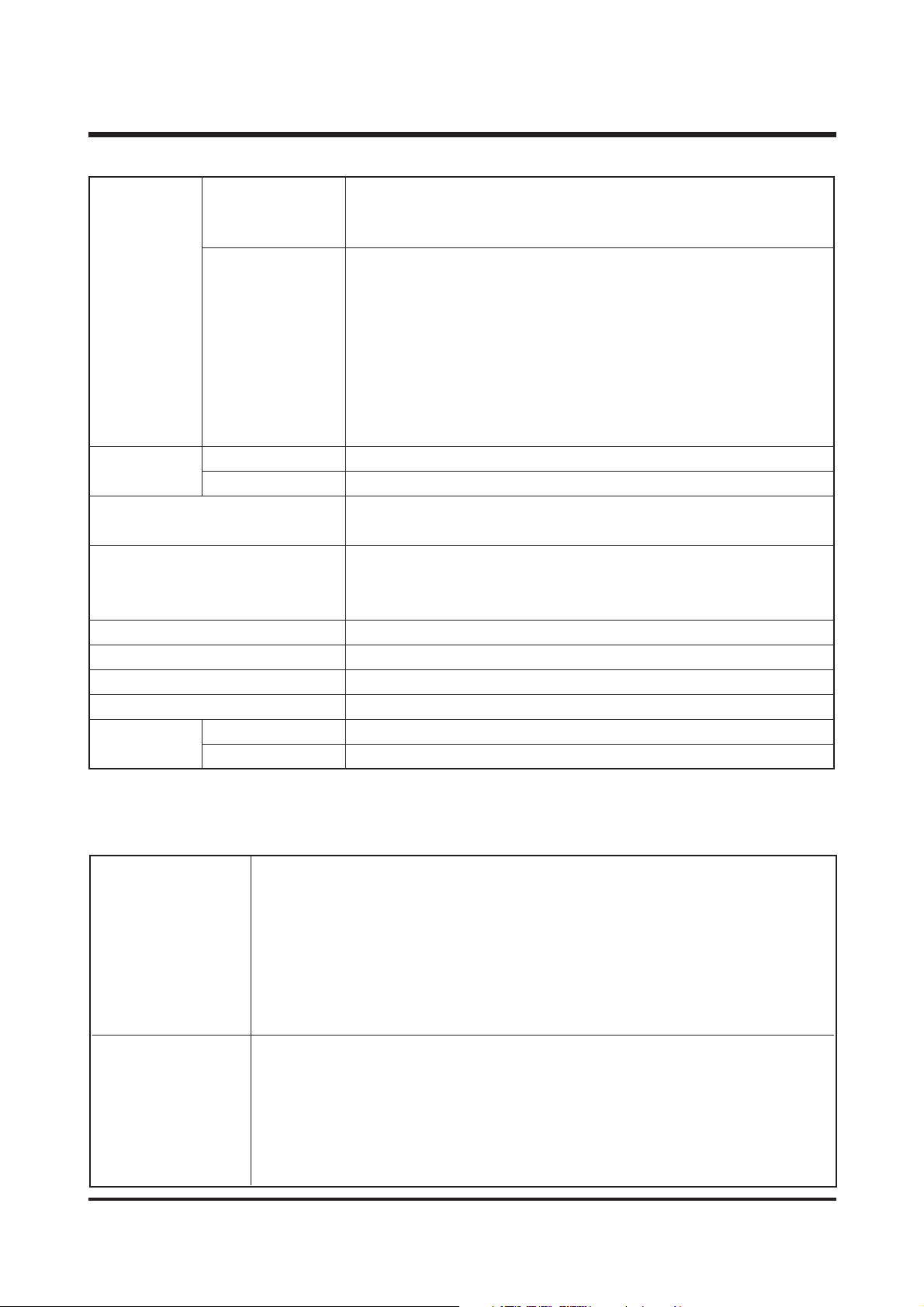
PC with processor better than MMX Pentium 233MHz (XP : Pentium II 300MHz)
Windows 98/98SE/2000/ME/XP
For Windows Minimum 32MB RAM (XP : 128MB)
140MB of available hard-disk space, USB port, CD-ROM drive,
800×600 pixels, 16-bit colour display compatible monitor
(24-bit color display recommended)
Power Mac G3 or later
Mac OS 9.0 ~ 10.2
For Macintosh Minimum 64MB RAM
110MB of available hard-disk space, USB port, CD-ROM drive,
QuickTime 4.0 or later for Movie Clip
5
Ⅰ. SPECIFICATION
22.. SSYYSSTTEEMM RREEQQUUIIRREEMMEENNTTSS
2272 : 2272X1704 pixels 2048 : 2048X1536 pixels
1600 : 1600X1200 pixels 1024 : 1024X768 pixels
640 : 640X480 pixels
2272 : Super fine (9) Fine (18) Normal (30)
2048 : Super fine (10) Fine (22) Normal (34)
1600 : Super fine (16) Fine (33) Normal (48)
1024 : Super fine (31) Fine (63) Normal (94)
640 : Super fine (65) Fine (123) Normal (185)
* These figures are measured by Internal memory based.
* These figures are measured under Samsung’s standard conditions and
may vary depending on shooting conditions and camera settings.
Type Single image/ Thumbnails/ Slide show/ Movie Clip
Editing Rotation, Trimming, Resizing
Digital output connector : USB 1.1
Video Out: NTSC, PAL (User selectable)
Primary battery : 2 x AA alkaline, Lithium, Ni-Mn, Ni-Zn / 1 x CR-V3
Rechargeable battery : 2 x AA Ni-MH, Ni-Cd / 1 x I-Pack ( SBP-1303)
* Included power source may vary depending on sales region.
Dimensions (WxHxD) 109 x 56.5 x 34mm
Weight Approx. 140g (without batteries and card)
Operating Temperature 0 ~ 40°C
Operating Humidity 5 ~ 85%
Camera Driver Storage Driver (Windows98/ 98SE)
Application Arcsoft PhotoImpression, Digimax Viewer, Digimax Reader
Capacity
(16MB
Internal Memory)
Storage
Image Size
Image Play
Interface
Power Source
Software
6
Ⅰ. SPECIFICATION
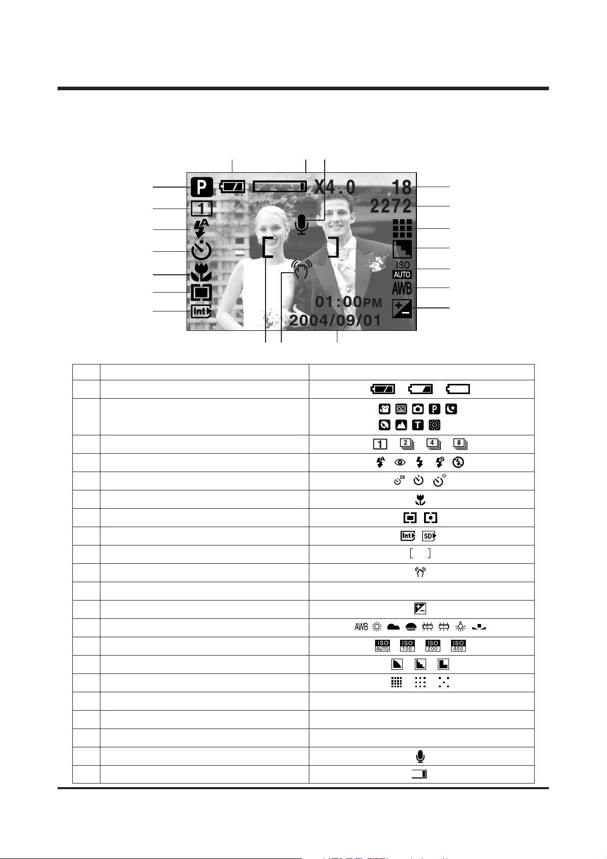
33.. TTFFTT LLCCDD PPAANNEELL MMAARRKK
■ Recording mode
②
③
④
⑤
⑥
⑦
⑧
⑫
⑬
⑭
⑮
⒃
⒔
⒕
⑪
⑨
⑩
⒗
⒖
①
No. Description Icons
1 Battery
3 Continuous shot
4 Flash
5 Self-timer
6 Macro
7 Metering
8 Card inserted indicator
9 Auto focus frame
10 Camera shake warning
11 Date/ Time 2004/09/01 01:00 PM
12 Exposure compensation
13 White Balance
14 ISO
15 Sharpness
16 Image quality
17 Image size 2272, 2048, 1600, 1024, 640
Number of available shots remaining 18
Remaining time (Movie clip/ Voice recording) 00:01:25/ 00:24:52
19 Voice memo
20 Optical zoom/ Digital Zoom rate
Recording mode
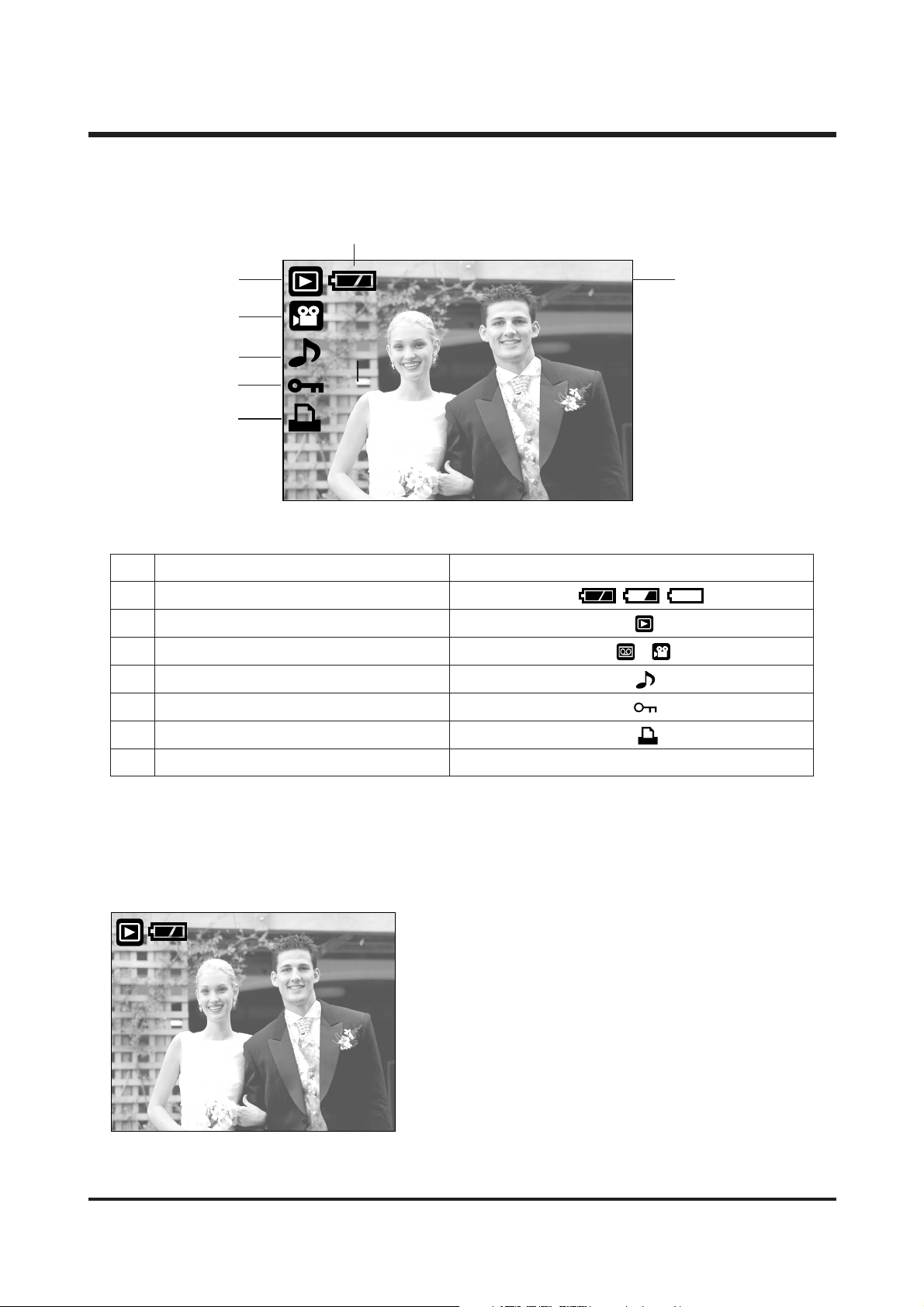
No. Description Icon
1 Battery
2 Play mode
3 File Type
4 Voice memo
5 Protect indicator
6 DPOF indicator
7 Stored image number 100-0009
7
Ⅰ. SPECIFICATION
100-0009
①
⑦
②
③
④
⑤
⑥
SIZE : 2272X1704 Size
AV : F2.9 Aperture value
TV : 1/18 Shutter speed
FLASH : OFF Whether or not the flash
is used.
DATE : 2004/09/01 Recording date
100-0009
SSIIZZEE :: 22227722XX11770044
AAVV :: FF22..99
TTVV :: 11//1188
FFLLAASSHH :: OOFFFF
DDAATTEE :: 22000044//0099//0011
■ Play mode
①
8
Ⅰ. SPECIFICATION
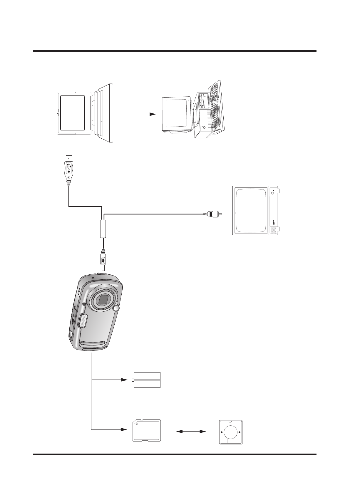
44.. CCOONNNNEECCTTIIOONN DDIIAAGGRRAAMM
USB Cable
Lap top
IBM / MAC
Video Cable
TV Monitor
SNB-2312
SD Card
Card Reader
9
Ⅰ. SPECIFICATION
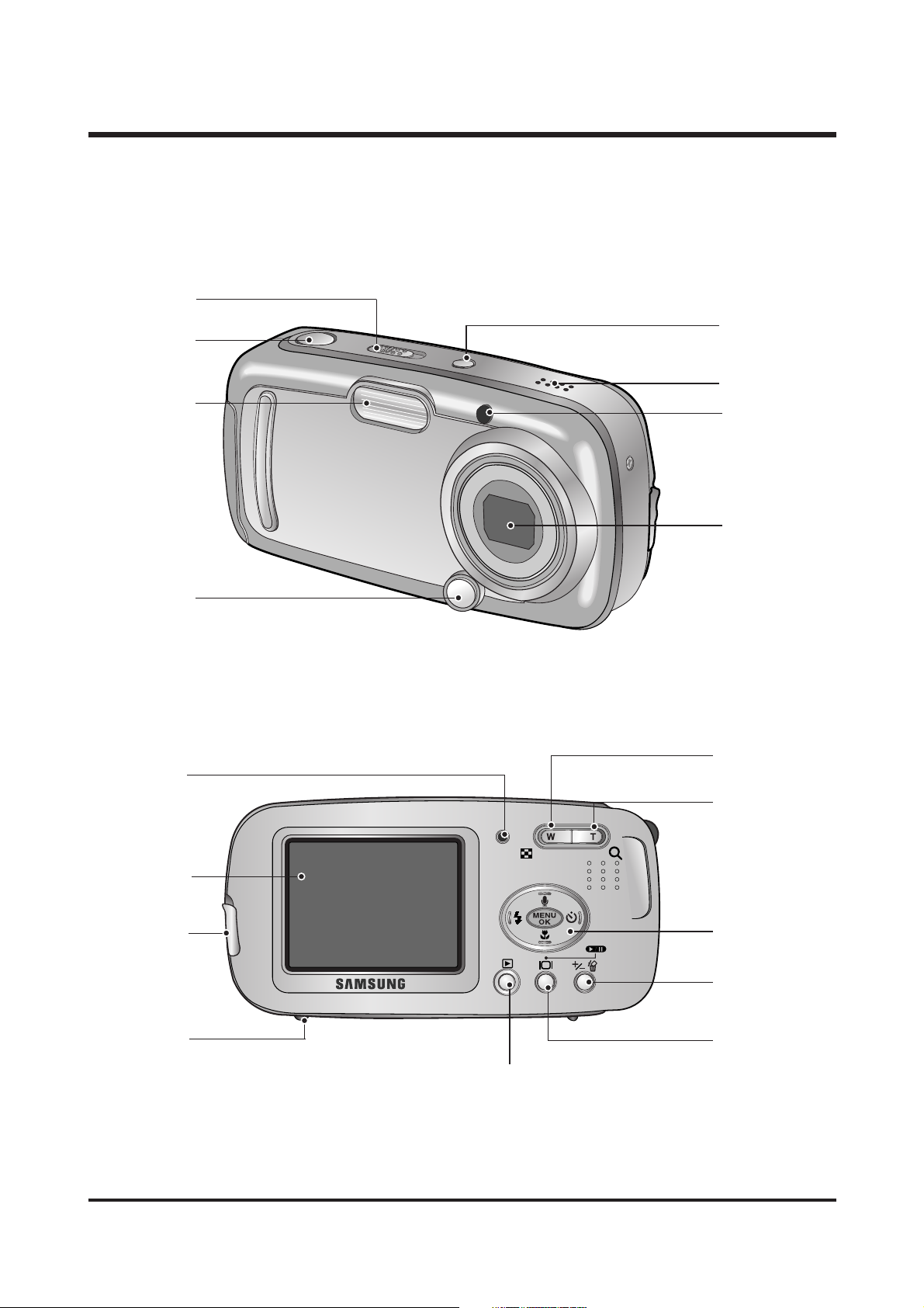
55.. IIDDEENNTTIIFFIICCAATTIIOO OOFF FFEEAATTUURREESS
Power button
Self-timer lamp
Microphone
Lens
Mode switch
Shutter button
Flash
Mirror for
self portrait
Zoom W button
(Thumbnail)
Zoom T button
(Digital zoom)
5-function button
Tripod socket
Play mode button
USB connection
port
Video connec-
tion terminal
+/-, DELETE
button
LCD button
LCD monitor
Camera status
lamp
10
Ⅰ. SPECIFICATION
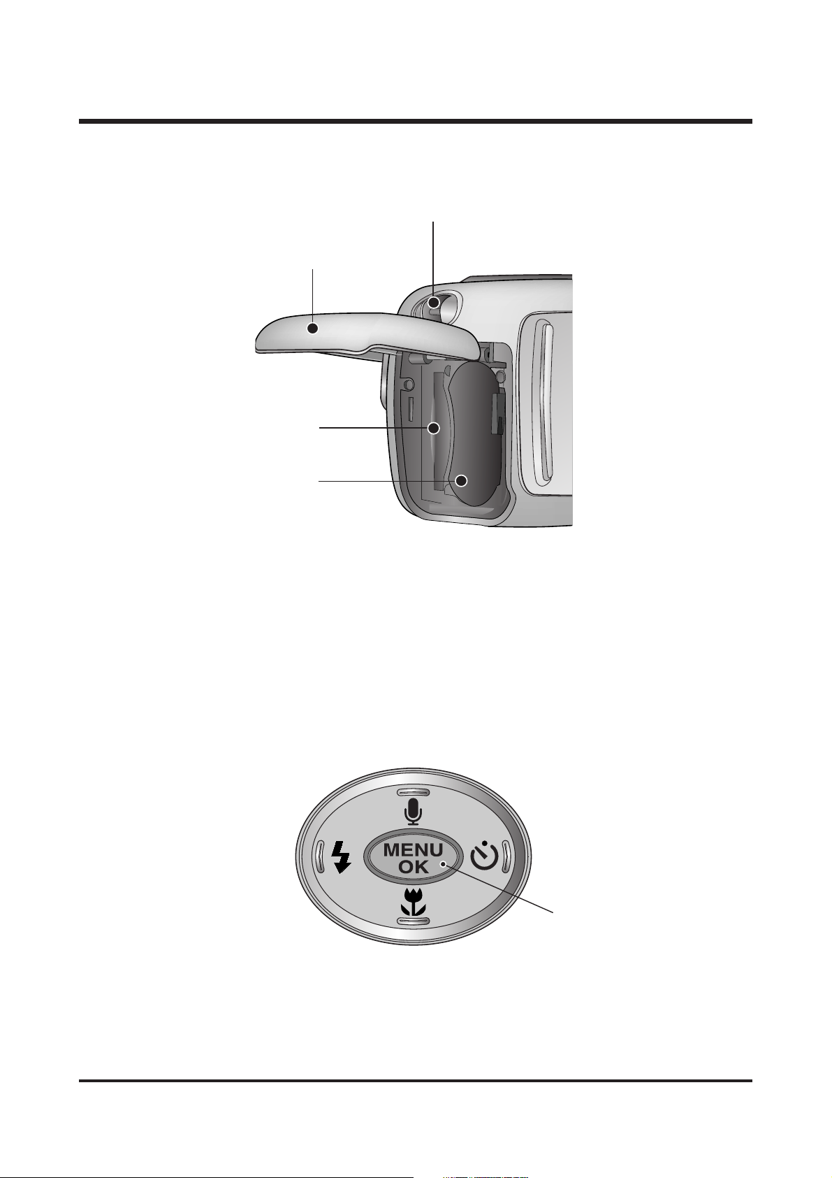
Battery chamber cover
Memory card slot
Strap eyelet
Battery chamber
FLASH/ LEFT
button
MENU/ OK
button
MACRO/ PLAY&PAUSE/ DOWN button
SELF-TIMER/
RIGHT button
Voice memo/ UP button
11
ⅡⅡ.. IINNSSTTAALLLLAATTIIOONN
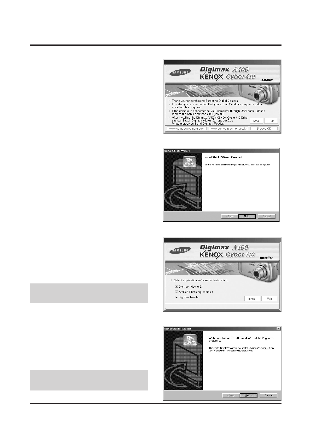
2. Camera driver installation is complete.
Click the [Finish] button.
1. Click the [Install] menu in the Autorun frame.
The camera driver is installed automatically.
● If you select [Exit] at the step 3, the appli-
cation program installation will be cancelled.
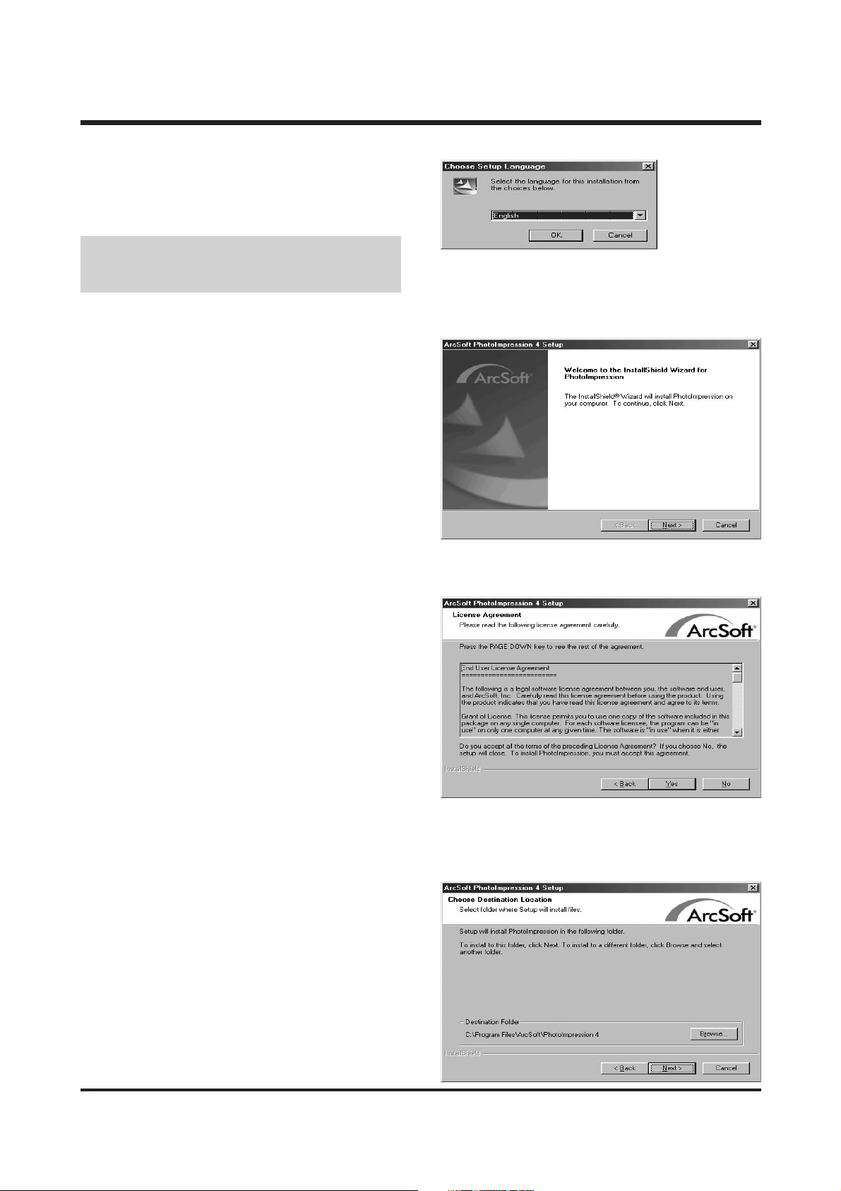
3. A window for which you can select application
software will be displayed. Select the application program and click the [Install] button.
Refer to page 90 for more information about
the application program.
4. Install Digimax Viewer.
Click [Next >] button.
● If you select [Cancel] at step 4, a window for
installing PhotoImpression will be displayed.
12
ⅡⅡ
.. IINNSSTTAALLLLAATTIIOONN
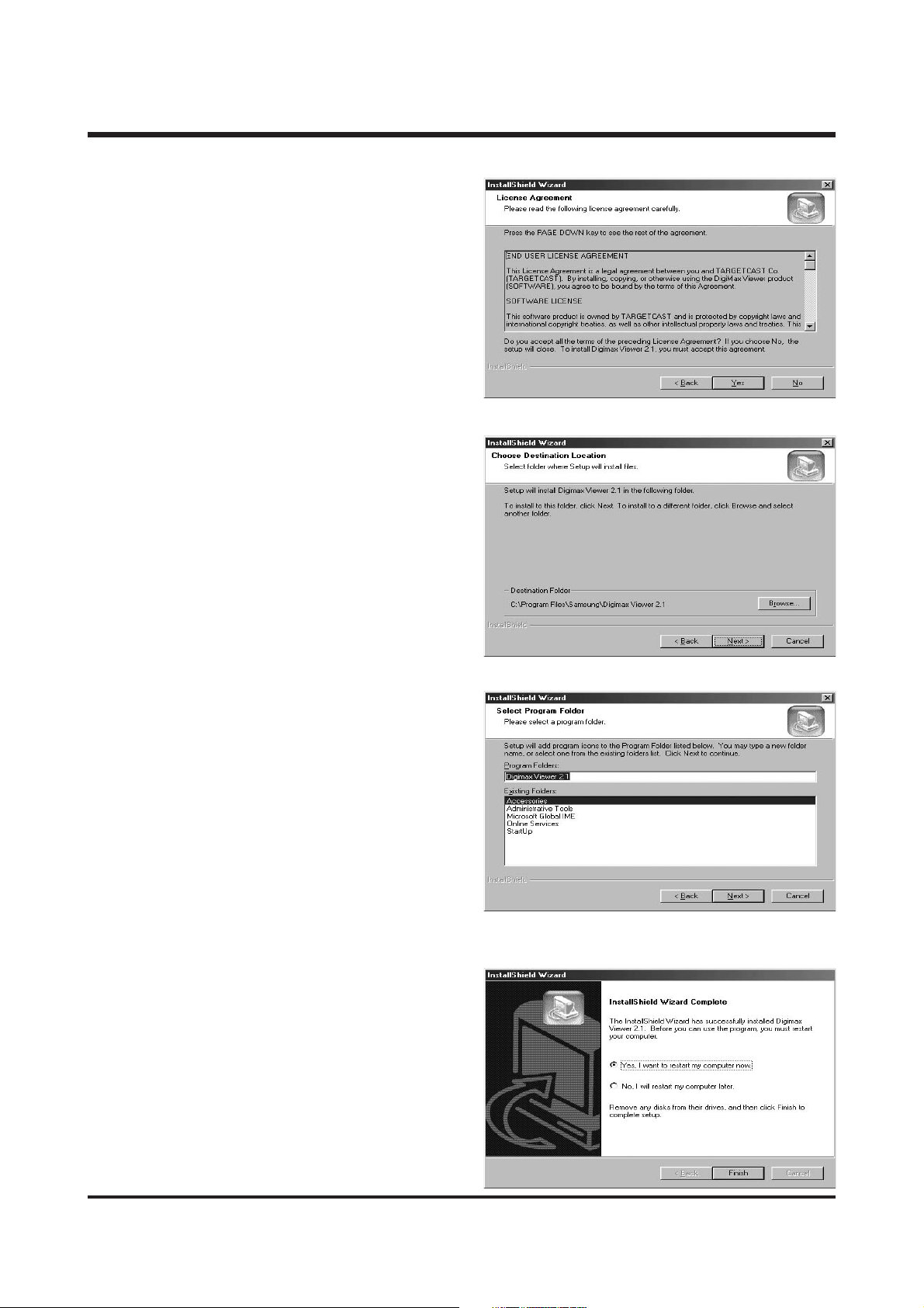
5. The Software License Agreement window will
be displayed. If you agree to this, click
[Yes], the window will then move to the
next step.
If you disagree, click [No] and the installation program will be cancelled.
6. A destination selection window will open.
Click [Next >].
To copy to the files to another folder, click
[Browse..] and choose a folder you want.
8. Digimax Viewer installation is successfully com-
pleted. Click the [Finish] button to install
PhotoImpression. The system will not reboot
even the [Yes, I want to restart the computer
now] option is selected.
* The frame 8 may not appear according to
the system requirements.
7. A window will open, asking you to choose a
folder to which program icons will be added.
Click [Next >] button. If you want to add
the program icons to a different folder,
choose another folder, and then click [Next
>] button.
13
ⅡⅡ
.. IINNSSTTAALLLLAATTIIOONN
9. The PhotoImpression installation window will
be displayed as shown alongside.
Click the [OK] button.
● If you select [Cancel] at step 9, a window for
installing Digimax Reader will be displayed.
10. A Welcome window will be displayed.
Click the [Next >] button.
12. A destination selection window will open. Click
[Next >]. To copy to the files to another
folder, click [Browse...] and choose a folder
you want.
11. The Software License Agreement window will
be displayed. If you agree to this, click [Yes],
the window will then move to the next step.
If you disagree, click [No] and the installation
program will be cancelled.
14
ⅡⅡ
.. IINNSSTTAALLLLAATTIIOONN
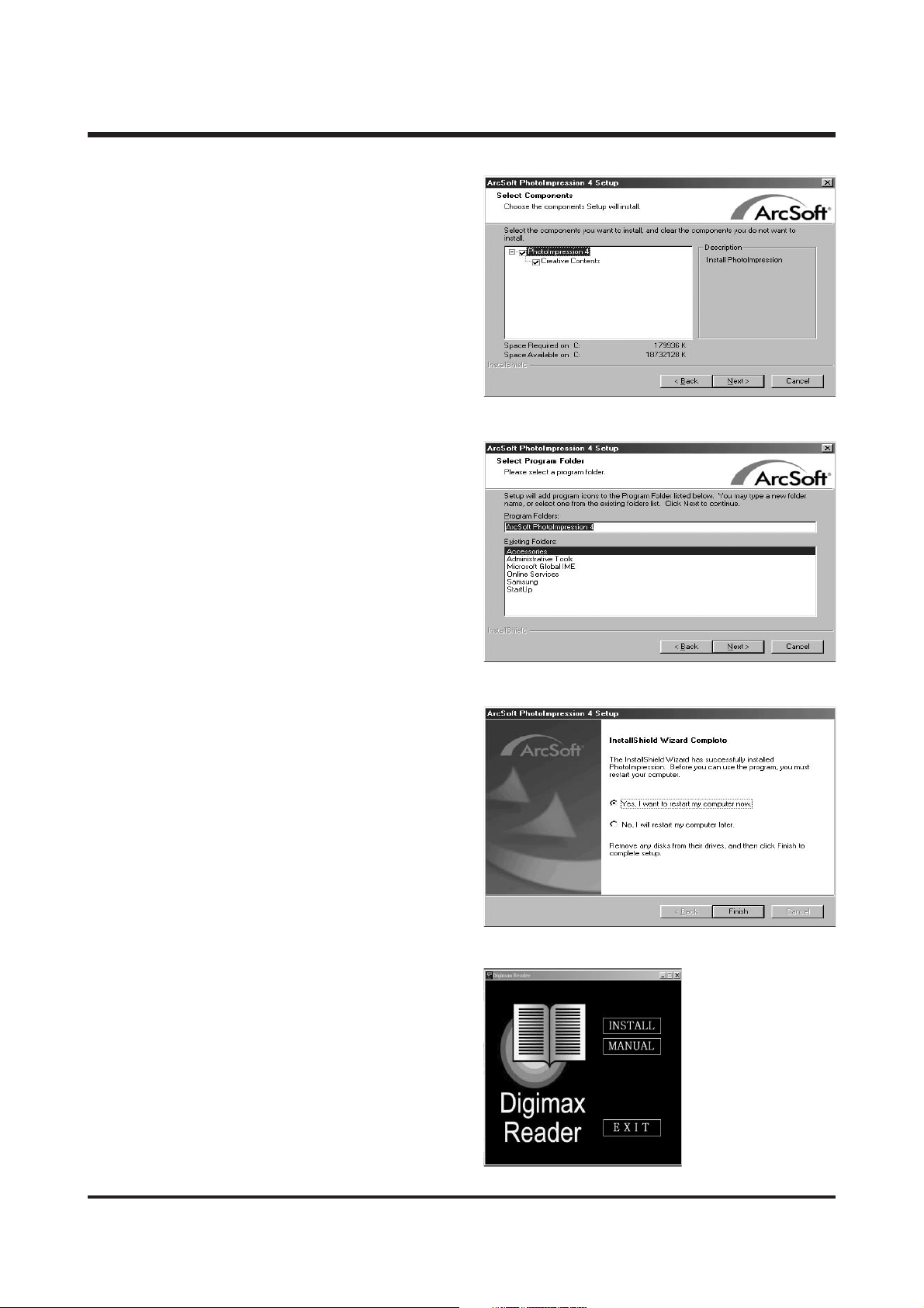
13. The [Select Components] window will appear.
Click [Next >] button.
14. A window will open, asking you to choose a
folder to which program icons will be added.
Click [Next >] button. If you want to add the
program icons to a different folder, choose
another folder, and then click [Next >] button.
15. PhotoImpression installation is successfully
completed. Click the [Finish] button to install
Digimax Reader.
* The system will not reboot even the [Yes, I
want to restart the computer now] option is
selected.
* The frame 15 may not appear according to
the system requirements.
16. Digimax Reader installation window will be
displayed as shown alongside.
Click the [INSTALL] button.
- Check the [MANUAL] button. Instructions
for using Digimax reader will be displayed.
- Click the [EXIT] button and Digimax reader
installation will be cancelled and the
Restart window will appear.
15
ⅡⅡ
.. IINNSSTTAALLLLAATTIIOONN
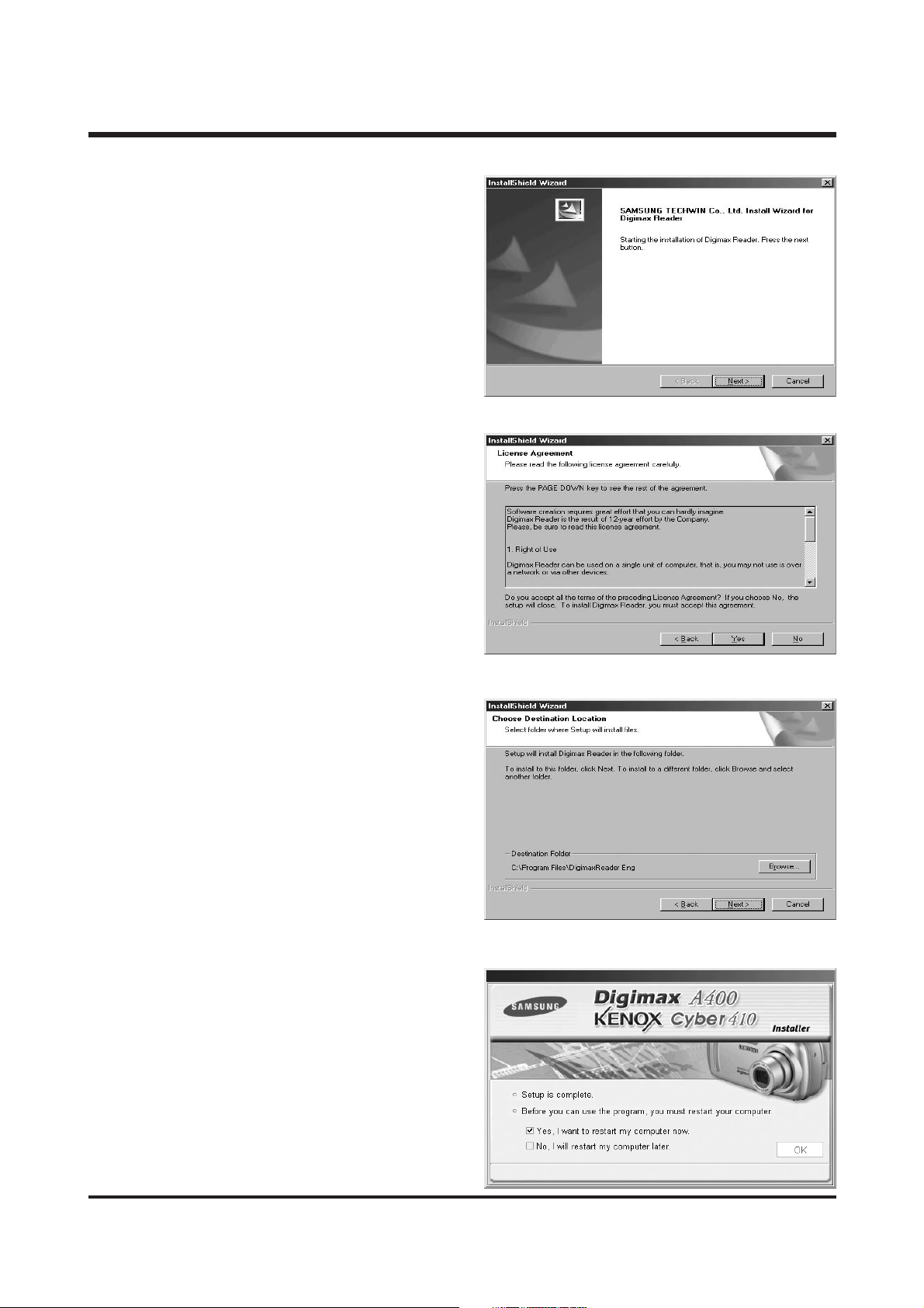
17. A window will open.
Click the [Next >] button.
18. The Software License Agreement window will
be displayed. If you agree to this, click
[Yes], the window will then move to the next
step.
If you disagree, click [No] and the installation program will be cancelled.
19. A destination selection window will open.
Click [Next >]. To copy to the files to another folder, click [Browse...] and choose a
folder you want.
20. Installation is complete. To apply changes,
you must restart the computer.
Select [Yes, I want to restart my computer
now], and then click [OK].
16
ⅡⅡ
.. IINNSSTTAALLLLAATTIIOONN
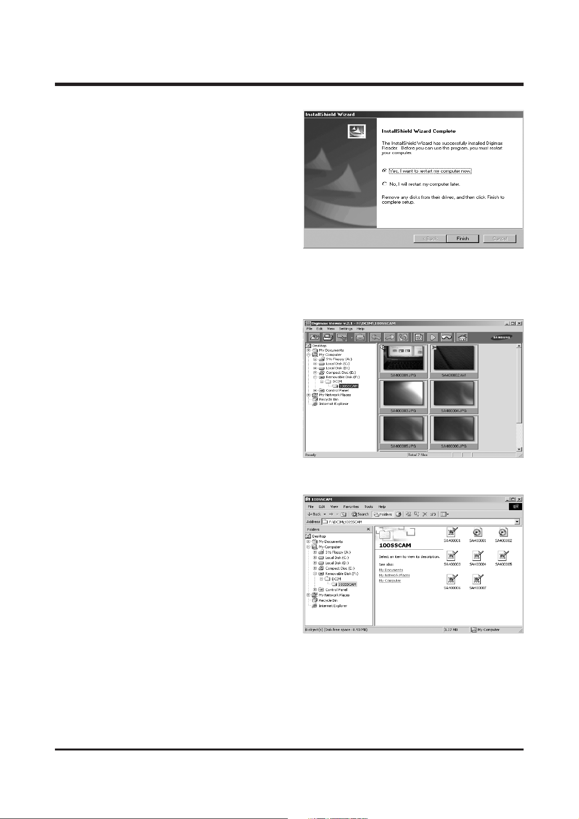
* The frame 20 may be displayed according to
the system requirements. Click the [Finish]
button to restart the computer.
21. After restarting the computer, connect the PC to the camera with the USB cable.
22. Turn the camera power on. [Found New
Hardware Wizard] will open and the computer will recognize the camera.
* If you have ever installed an image viewer
program or your OS is Windows XP, an
image viewer program will open. If the
image viewer program opens, the camera
driver was setup successfully.
23. If you can see [Removable Disk] under
[My computer], the camera driver installation was successful. Now you can transfer
image files from the camera to PC via the
USB cable.

17
ⅡⅡ
.. IINNSSTTAALLLLAATTIIOONN
● If you have installed the camera driver, [Found New Hardware Wizard] may not open.
● On a Windows 98 or 98 SE system, the Found New Hardware Wizard dialog box opens and a window
asking you to select a driver file may appear. In this case, specify "USB Driver" in the CD supplied.
● Before connecting the camera to the PC, You should first install the camera driver.
● After installing the camera driver, you have to restart your PC.
● If you connect the camera to the PC before installing the camera driver, the [Found New Hardware
Wizard] will open.
In this case, cancel the [Found New Hardware Wizard] and disconnect the camera. Install the camera
driver and connect the camera to the PC again.
● Should the computer not find the camera driver after installation, please try one or more of the fol-
lowing measures.
1. Delete the camera driver, and re-install the driver.
2. Refer to FAQ to check for a possible solution to the problem.
3. If your PC’s central processing unit is VIA chip (This is shown in the USB Host Controller), download
the patch file from the Samsung Camera web page. (http://www.samsungcamera.com)
18
ⅢⅢ.. EEXXPPLLOODDEEDD VVIIEEWWSS AANNDD PPAARRTTSS LLIISSTT
1818
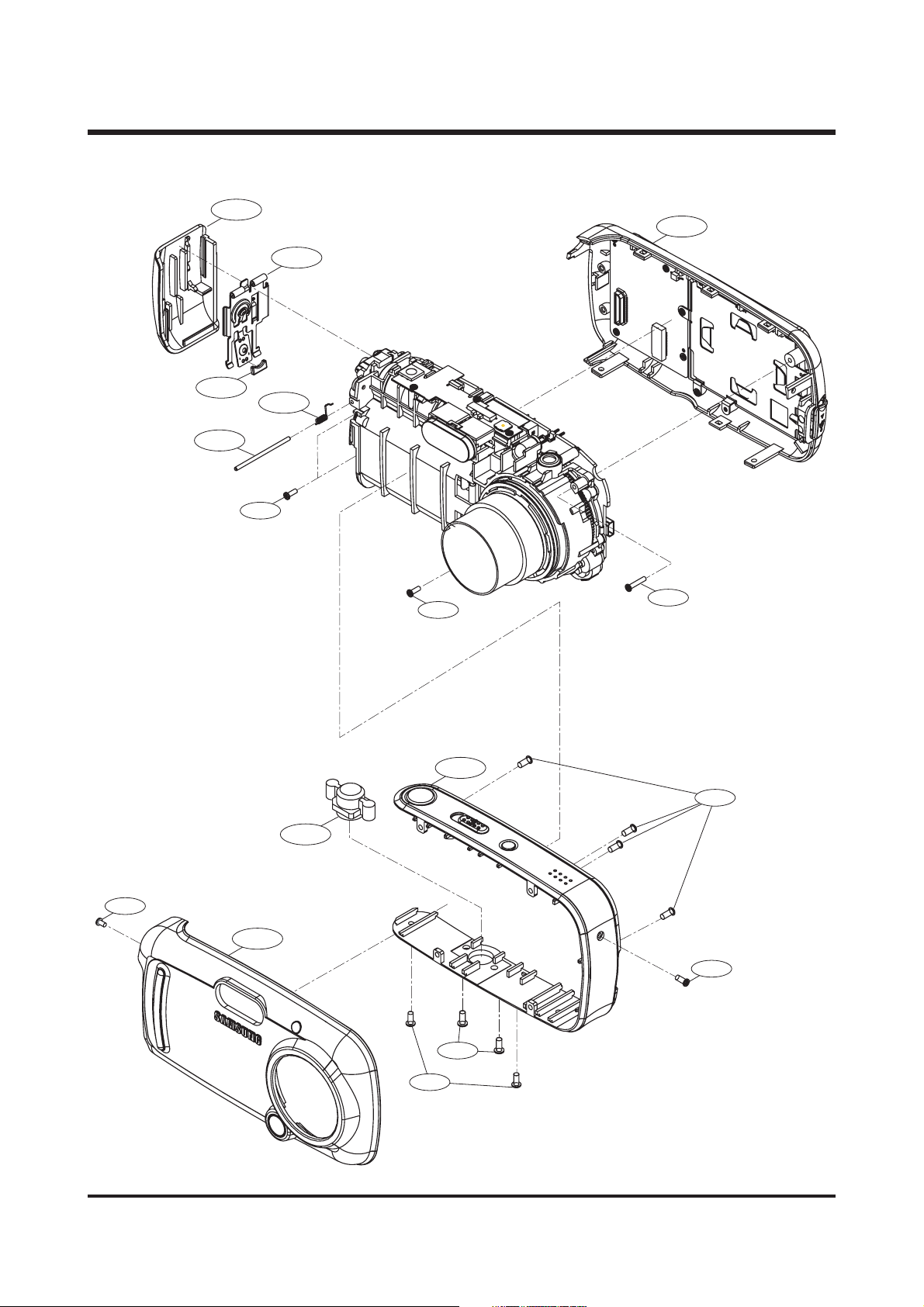
1. MAIN ASSEMBLY
1-3
1-5
1-8
1-4
1-6
1-13
1-7
1-9
1-12
1-15
1-2
1-16
1-14
1-1
1-10
1-15
1-11

19
Ⅲ. EXPLODED VIEWS AND PARTS LIST
1919
FFiigg..NNoo.. PPaarrttss NNoo.. PPaarrttss NNaammee QQ''ttyy RReemmaarrkkss
1-1 Q9007967001A FRONTCOVERASS'Y-KENOXCYBER410 1
1-1 Q9007967101A FRONTCOVERASS'Y-DIGIMAXA400 1
1-2 Q9007967201A MIDDLECOVERASS'Y 1
1-3 Q7217338601A BATTERYCOVER 1
1-4 Q7217338701A BATTERYSTOPER 1
1-5 Q7017044401A BATTERYCONTACTSHEET 1
1-6 Q7411103801A BATTERYSHAFT 1
1-7 Q6107061001A BATTERYCOVERSPRING 1
1-8 Q9007967301A BACKCOVERASS'Y 1
1-9 Q7211079001A TRIPODBASE 1
1-10 Q6003045301A SCREW 2
1-11 Q6003038901A SCREW 1
1-12 Q6003045401A SCREW 1
1-13 Q6003045501A SCREW 2
1-14 Q6003045601A SCREW 1
1-15 Q6003045701A SCREW 2
1-16 Q6003041801A SCREW 4
▶▶ PPAARRTTSS LLIISSTT
20
Ⅲ. EXPLODED VIEWS AND PARTS LIST
2020
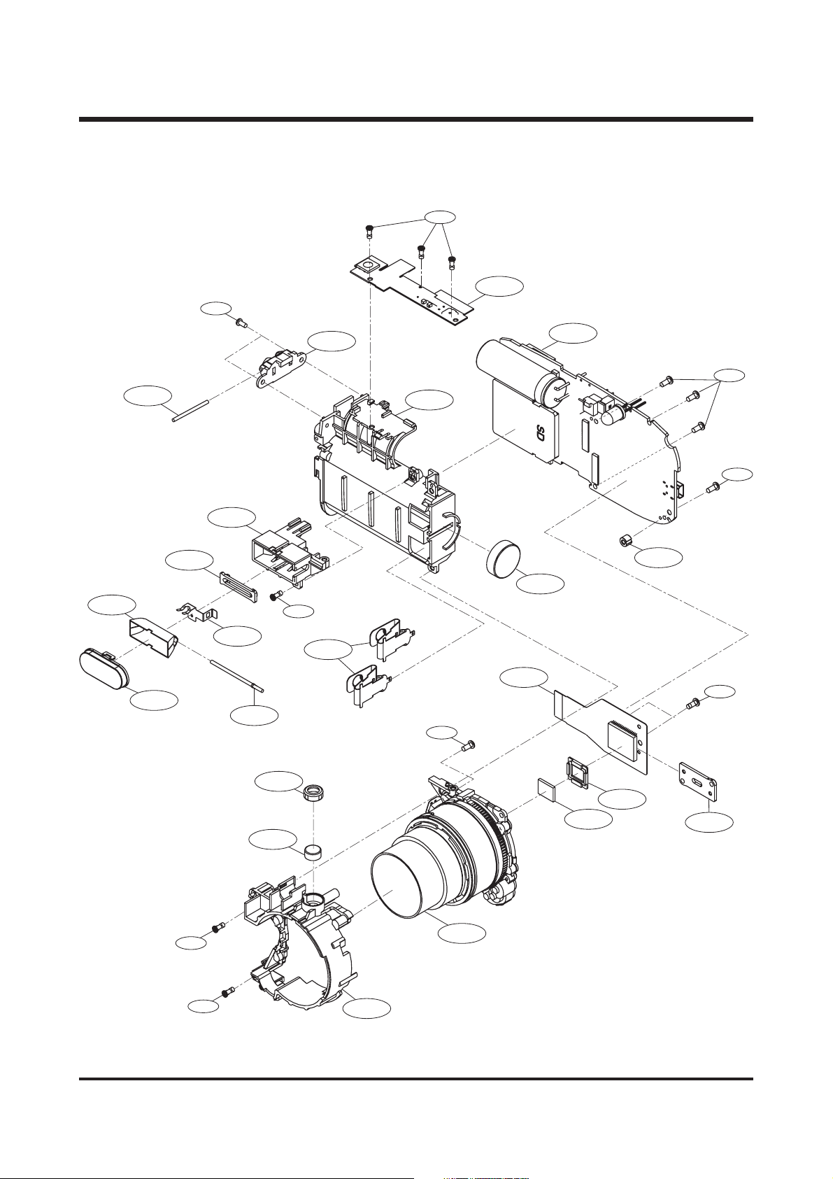
2. BODY ASSEMBLY
2-21
2-23
2-11
2-17
2-13
2-16
2-18
2-15
2-19
2-14
2-24
2-12
2-27
2-2
2-21
2-1
2-22
2-26
2-10
2-5
2-21
2-21
2-25
2-24
2-8
2-9
2-4
2-3
2-7
2-6
2-20

21
Ⅲ. EXPLODED VIEWS AND PARTS LIST
2121
FFiigg..NNoo.. PPaarrttss NNoo.. PPaarrttss NNaammee QQ''ttyy RReemmaarrkkss
2-1 Q7211079101A BATTERYBOX 1
2-2 Q9008080401A MAINBOARDASS'Y 1
2-3 Q9002134001A BARRELASS'Y 1
2-4 Q7212185801A LENSCORE 1
2-5 Q9008080501A CCDFPCBASS'Y 1
2-6 Q7309044401A CCDRUBBER 1
2-7 Q2904002701A IRCUT 1
2-8 Q7309044501A MICRUBRING 1
2-9 Q3003000201A MIC 1
2-10 Q3002001401A BUZZER 1
2-11 Q9008080601A TOPBOARDASS'Y 1
2-12 Q7217338801A STRAPHOLDER 1
2-13 Q7411116401A STRAPSHAFT 1
2-14 Q0611004001A FLASHXETUBE 1
2-15 Q7214000501A FLASHHOLDER 1
2-16 Q7217338901A FLASHACRLY 1
2-17 Q7014004901A FLASHREFLECTOR 1
2-18 Q7309044601A FLASHRUBBER 1
2-19 Q7014005001A FLASHCONTACT 1
2-20 Q7012082801A CCDPLATE 1
2-21 Q6003041801A SCREW 8
2-22 Q6003031401A SCREW 3
2-23 Q6003045801A SCREW 3
2-24 Q6003045901A SCREW 2
2-25 Q6003031801A SCREW 1
2-26 Q7211079201A SUPPORTBOSS 1
2-27 Q7011046701A BATTERYCONTACTUPPER 2
▶▶ PPAARRTTSS LLIISSTT
22
Ⅲ. EXPLODED VIEWS AND PARTS LIST
2222
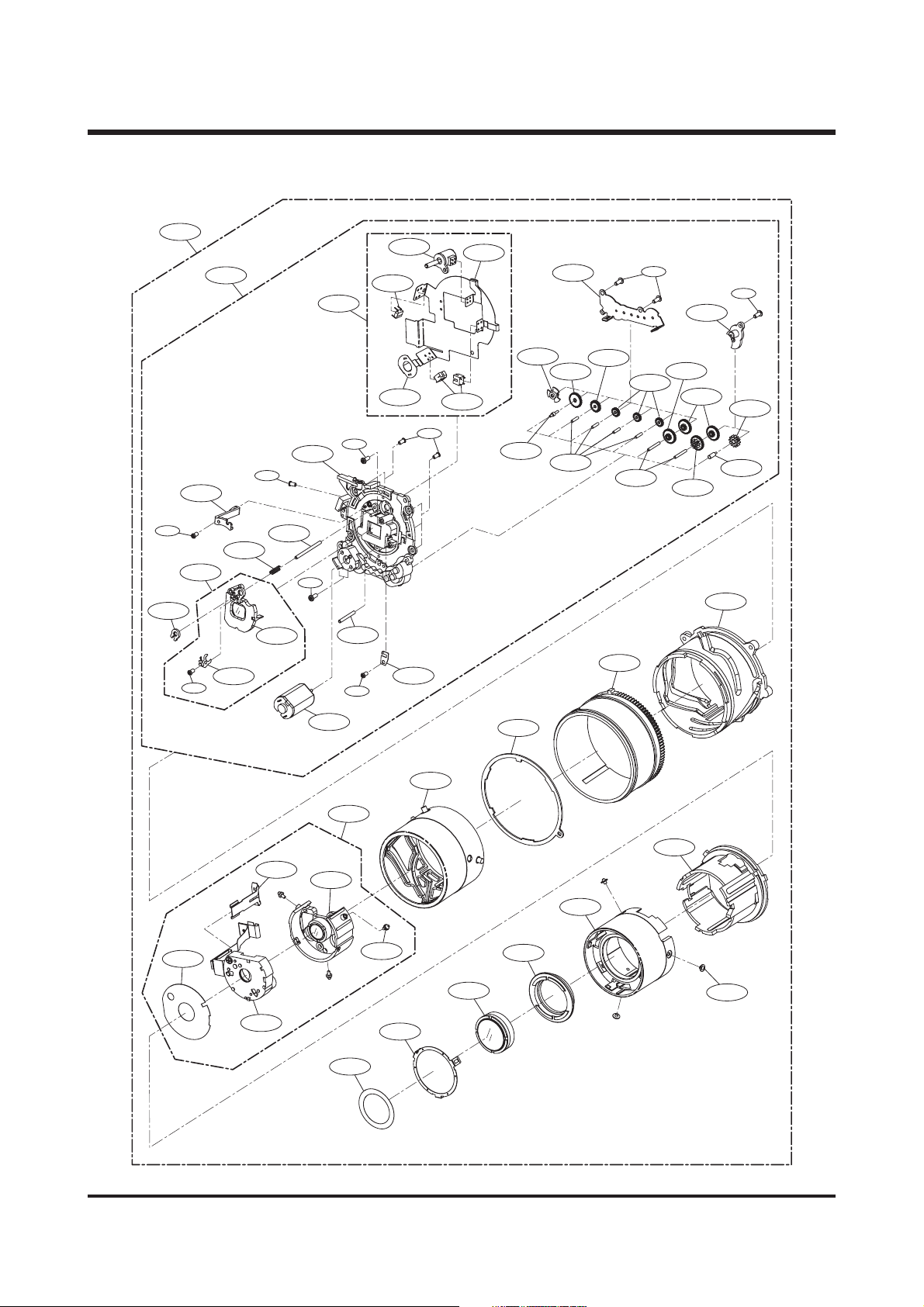
3. BARREL ASSEMBLY
3-36
3-58
3-59
3-35
3-30
3-33
3-1
3-32
3-34
3-37
3-31
3-3
3-2
3-10
3- 23
3-22
3-4
3-21
3-28
3-26
3-25
3-29
3-55
3-27
3-24
3-5
3-11
3-20
3-12
3-6
3-18
3-53
3-7
3-38
3-17
3-15
3-14
3-19
3-16
3-22
3-13
3-8
3-54
3-44
3-42
3-46
3-9
3-41
3-40
3-57
3-45
3-49
3-51
3-56
3-52
3-39
3-47
3-48
3-50

23
Ⅲ. EXPLODED VIEWS AND PARTS LIST
2323
Fig.No. Parts No. Parts Name Q'ty Remarks
3-1 Q9002120001A LENS BASE ASS'Y 1
3-2 Q7212172505A LENS BASE 1
3-3 Q7411097601A AF GUIDER BAR_A 1
3-4 Q7411097701A AF GUIDER BAR_B 1
3-5 Q7411085902A ZOOM GEAR_A SHAFT 1
3-6 Q7411097801A ZOOM GEAR_B SHAFT 4
3-7 Q7411090001B ZOOM GEAR_C SHAFT 2
3-8 Q7411097901B ZOOM GEAR_D SHAFT 1
3-9 Q3107001701A ZOOM MOTOR 1
3-10 Q9611142007 SCREW 2
3-11 Q7212160001B ZOOM MOTOR GEAR 1
3-12 Q7212160101A ZOOM GEAR_A 1
3-13 Q7411085802A ZOOM GEAR_D 1
3-14 Q7411085702A ZOOM GEAR_C 1
3-15 Q7411085601B ZOOM GEAR_B 1
3-16 Q7212160602B ZOOM GEAR_E 2
3-17 Q7212172701A ZOOM GEAR_H 3
3-18 Q7212173801A ZOOM GEAR_G 1
3-19 Q7212172601A ZOOM COVER 1
3-20 Q7012075903A ZOOM COVER_B 1
3-21 Q9761142507 SCREW 1
3-22 Q0961900301A SCREW 2
3-23 Q9008062101A MAIN FPCB ASS'Y 1
3-24 Q4101025801A MAIN F PCB 1
3-25 Q9002104301A AF MOTOR ASS'Y 1
3-26 Q4101026701A ZOOM MOTOR FPCB 1
3-27 Q0608001001A PHOTO INTERRUPTER 2
3-28 Q0608000701A PHOTO REFLECTOR 1
3-29 Q7012076001A AF PI CAP 1
3-30 Q9002121701A 3rd LENS BARREL ASS'Y 1
3-31 Q9002119301A 3rd LENS ASS'Y 1
3-32 Q7012069406C AF LIMIT SPRING 1
3-33 Q6001014001A SCREW 1
3-34 Q6107048305A 3RD LENS BARREL SPRING 1
3-35 Q7212174303A AF GUIDE HOLDER 1
3-36 Q0961900101A SCREW 1
3-37 Q0994913101A SCREW 1
3-38 Q6003040401A SCREW 2
3-39 Q7212172103A GUIDE PLATE 1
3-40 Q9002119401A 2nd LENS BARREL ASS'Y 1
3-41 Q9002119101A 2nd LENS ASS'Y 1
3-42 Q9005017101A SHUTTER ASS'Y 1
3-43 Q0961900301A SCREW 2
3-44 Q7409137303C SHUTTER SHIELD 1
3-45 Q7411085305A 2ND MOVE PIN 3
3-46 Q7012075703A F_PCB GUIDER 1
3-47 Q7212172003A ZOOM RING 1 SIL/WHT
Q7212179601A ZOOM RING 1 GRAY
3-48 Q7212171702A SLIP RING 1
3-49 Q7012075502A 1ST PUSH PLATE 1
3-50 Q7411097502A 1st MOVE PIN 3
3-51 Q7212172201A CAM BARREL 1 SIL/WHT
Q7212179701A CAM BARREL 1 GRAY
3-52 Q7012075802A FINDER HOLDER 1
3-53 Q9002119501A OUTER GUIDE BARREL ASS'Y 1
3-54 Q7212172303A OUTER CAM BARREL 1
3-55 Q9761173007 SCREW 5
3-56 Q9002119001A 1st LENS ASS'Y 1
3-57 Q7409138001A FRONT SHIELD 1
3-58 Q7012069301A AF CLIP 1
3-59 Q9002121901A BARREL SUB ASS'Y 1 SIL/WHT
Q9002132401A BARREL SUB ASS'Y 1 GRAY
▶▶ PPAARRTTSS LLIISSTT
24
Ⅲ. EXPLODED VIEWS AND PARTS LIST
2424
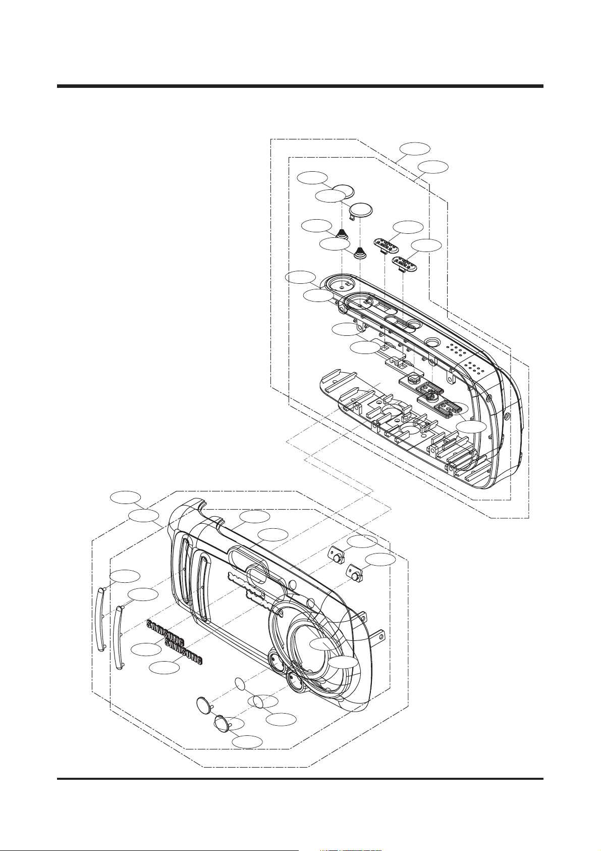
4. FRONT COVER ASSEMBLY
4-8
4-8
4-14
4-14
4-1
4-1
4-6
4-9
4-13
4-9
4-13
4-12
4-12
4-10
4-10
4-11
4-11
4-2
4-2
4-3
4-3
4-4
4-4
4-7
4-6
4-7
4-5
4-5
4-
4-

25
Ⅲ. EXPLODED VIEWS AND PARTS LIST
2525
FFiigg..NNoo.. PPaarrttss NNoo.. PPaarrttss NNaammee QQ''ttyy RReemmaarrkkss
4-1 Q9007967001A FRONTCOVERASS'Y-KENOXCYBER410 1
4-1 Q9007967101A FRONTCOVERASS'Y-DIGIMAXA400 1
4-2 Q7217339001A FCOVERGRIP 1
4-3 Q7217303501A SAMSUNGLOGO 1
4-4 Q7217339101A FCOVERDECO. 1
4-5 Q7217339201A REDEYEACRLY 1
4-6 Q7217339301A FRONTCOVER-KENOXCYBER410 1
4-6 Q7217339401A FRONTCOVER-DIGIMAXA400 1
4-7 Q7409175101A TAPE 1
4-8 Q9007967201A MIDDLECOVERASS'Y 1
4-9 Q7217339501A MIDDLECOVER 1
4-10 Q7217339601A MODEKEYLINKAGE 1
4-11 Q7217339701A POWERKEY 1
4-12 Q7217339801A MODEKEY 1
4-13 Q6107061101A SHUTTERSPRING 1
4-14 Q7217339901A SHUTTERBUTTONASS'Y 1
▶▶ PPAARRTTSS LLIISSTT
26
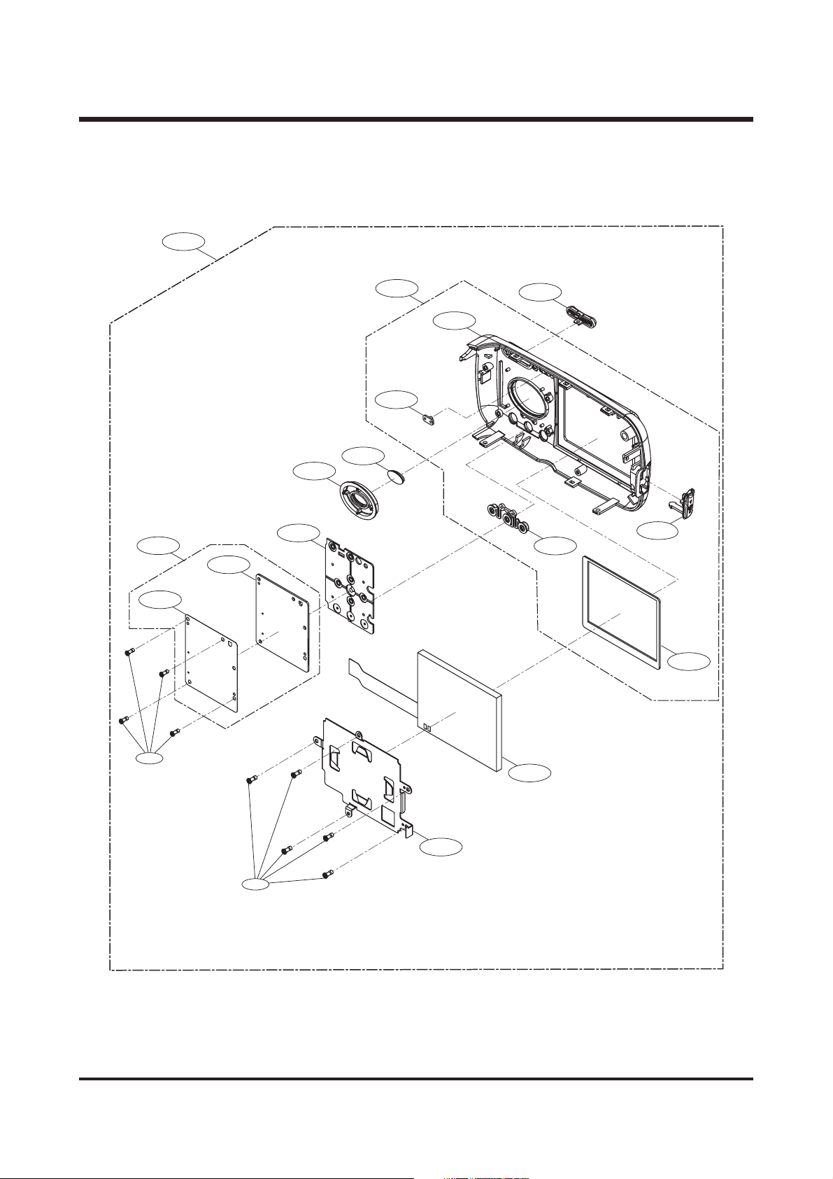
Ⅲ. EXPLODED VIEWS AND PARTS LIST
55.. BBAACCKK CCOOVVEERR AASSSSEEMMBBLLYY
1
5-1
5-10
5-11
5-16
5-9
5-6
5-8
5-2
5-7
5-4
5-5
5-3
5-13
5-12
5-17
5-14
5-15
5-18

27
Ⅲ. EXPLODED VIEWS AND PARTS LIST
FFiigg..NNoo.. PPaarrttss NNoo.. PPaarrttss NNaammee QQ''ttyy RReemmaarrkkss
5-1 Q9007967301A BACKCOVERASS'Y 1
5-2 Q9007967401A BACKCOVERSUBASS'Y 1
5-3 Q7308015301A USBCOVER 1
5-4 Q7217340001A ZOOMBUTTON 1
5-5 Q7217340101A BACKCOVER 1
5-6 Q7217340201A SELECTKEY 1
5-7 Q7217340301A READYACRLY 1
5-8 Q7217340401A ASS'YOKKEY 1
5-9 Q7307005601A KEYRUBBERSILICON 1
5-10
5-11 Q7409175201A METALDOME 1
5-12 Q7409175301A TFTSPONGE 1
5-13 Q7217340501A FUNCTIONKEY 1
5-14 Q0704010601A TFTLCD 1
5-15 Q7017044501A LCDSUPPORTPLATE 1
5-16 Q9008080701A KEYBOARDASS'Y 1
5-17 Q6003046001A SCREW 4
5-18 Q6003042301A SCREW 5
▶▶ PPAARRTTSS LLIISSTT
28
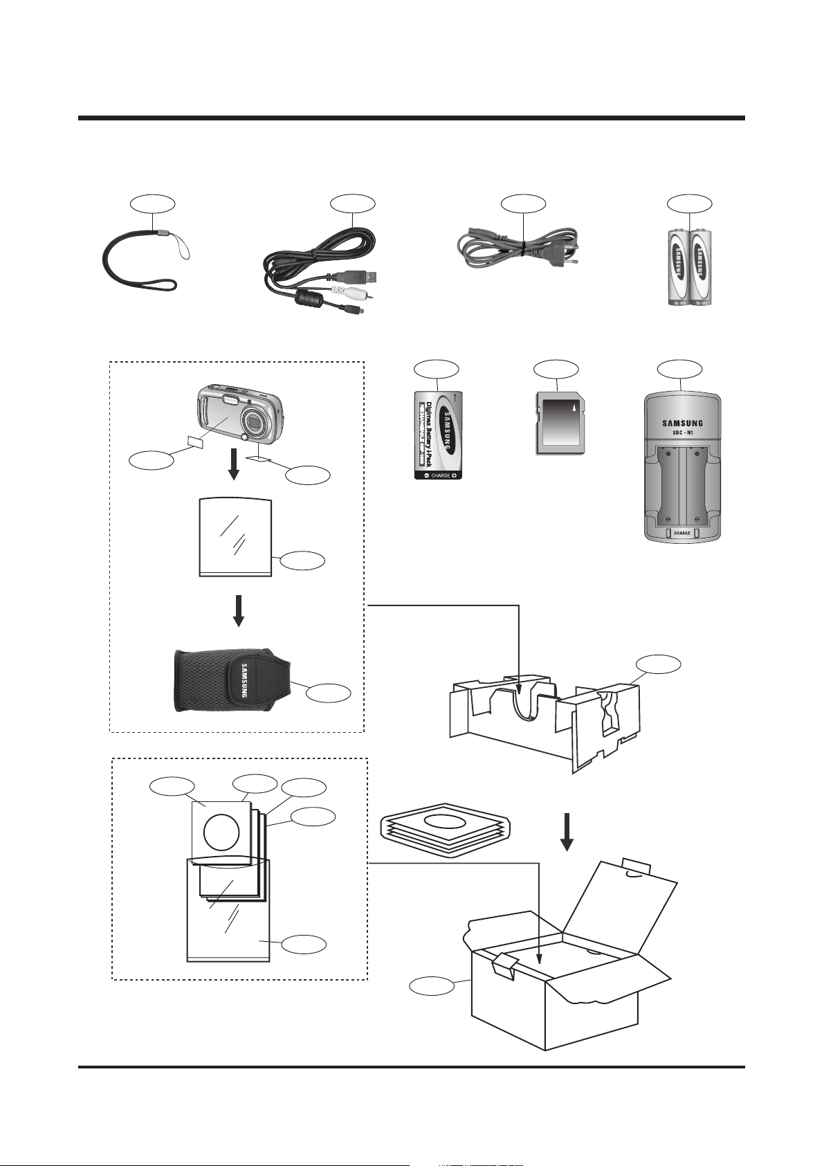
Ⅲ. EXPLODED VIEWS AND PARTS LIST
66.. PPAACCKKIINNGG IITTEEMM
6-9
6-13
6-12
6-1
6-10
6-16 6-15
6-14
6-186-7
6-11
6-5
6-3
6-4
6-6
6-7
6-2
6-8
 Loading...