

Page 1

46
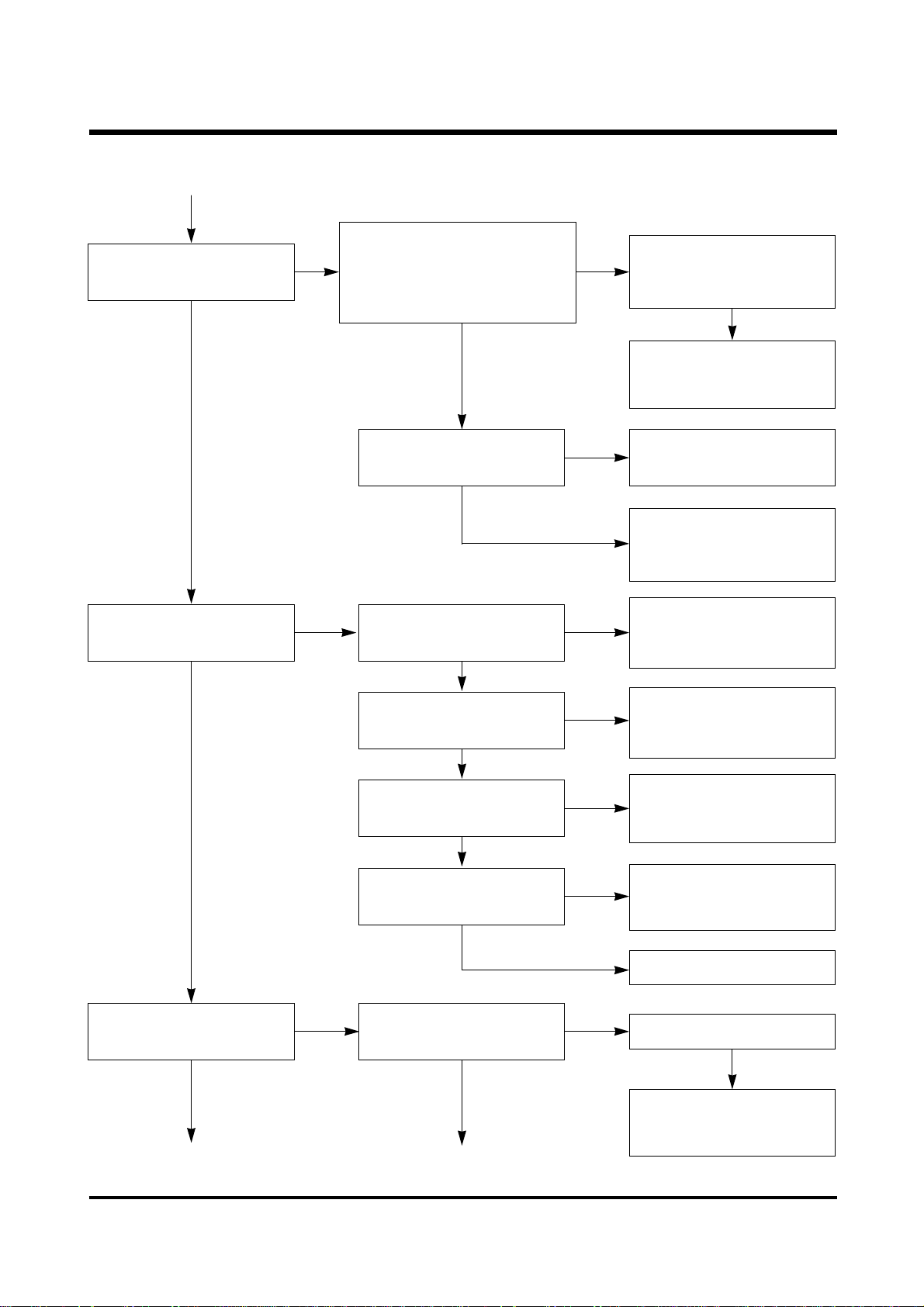
Ⅵ. TROUBLESHOOTING & MAINTENANCE
When using the adaptor, the
power does not turn ON.
If using the battery, the
power doesn’t turns ON.
Poor soldering of Power
diode.(Power PCB D10)
Resolding the Diode
전원 Diode 납땜 불량
Replace the Fuse
(Power PCB F2)
See 6-1.POWER Error
Disconnected FUSE.
(Broken FUSE)
Replace the Battery CapPoor contacts of Battery Cap
Verify if disconnected
between Battery spring
and Power Board.
When using the battery,the
power does not turn ON.
See 6-2. SUB PCB Error
See 6-1. POWER Error
Check the LED FPCB
LED is illuminated.
The letter does not appear
on TN LCD
See 6-4. CAMERA Mode
Error
Check the booting by mode.
Poor booting in CAMERA
Mode
See 6-3.MAIN PCB Error
Booting does not operate.
YES
YES
YES
YES
NO
NO
NO
NO
NO
NO
NO
NO
NO
YES
YES
YES
YES
YES
Page 2

47
Ⅵ. TROUBLESHOOTING & MAINTENANCE
KEY IN Error See 6-2. KEY IN Error
YES
Image display Error TFT LCD Output Error
TV Monitor output Error
See 6-5. LCD Error
See 6-6. TV Output Error
See 6-7. Image Error
YES
Moving Image display Error
YES
See 6-9. Replay Error
Replay Error
YES
See 6-10. CARD ErrorCARD related Error
YES
See 6-11. Strobo Error
Strobo luminescent Error
YES
See 6-12. Barrel Error
See 6-13. Software
Installing Error
See 6-14. USB Error
See 6-15. SERIAL Error
Lens drive
(Zoom,Shutter,AF)Error
YES
NO
NO
NO
NO
NO
NO
NO
NO
NO
YES
YES
Photographing Error
Though the shutter pressed,
it will not photograph
Image recording Error
See 6-2. KEY IN Error
See 6-8. Card Recording
Error
YES
NO
YES
PC Interface Error
Program Installation Error
Serial Interface Error
YES
NO
NO
YES
YES
YES
YES
USB Interface Error
Page 3

48
Ⅵ. TROUBLESHOOTING & MAINTENANCE
Check for overcurrent with
VCC connected
Check if C4,C18,C51,C52,C103
damaged and shorted.
Lift Pin 5 of U3 and check
for overcurrent with power
on.
Lift L9 and check for
overcurrent with power on.
Replace damaged TALTAL
Replace U1
Replace U3
Replace
Q8
Replace
C50
Replace
Q7
Replace
Q9
Replace
U2
Replace
Q1
Replace
Q2
Detach D9 (from a board)
and check for overcurrent
with
Detach C50 and check for
overcurrent with power on.
Detach Q7 and check for
overcurrent with power on.
Detach Q9 and check for
overcurrent with power on.
Detach Q1 and check for
overcurrent with power on.
Detach Q2 and check for
overcurrent with power on.
YES
NO
NO
NO
NO
NO
NO
NO
NO
NO
NO
NO
YES
YES
YES
YES
YES
YES
YES
YES
YES
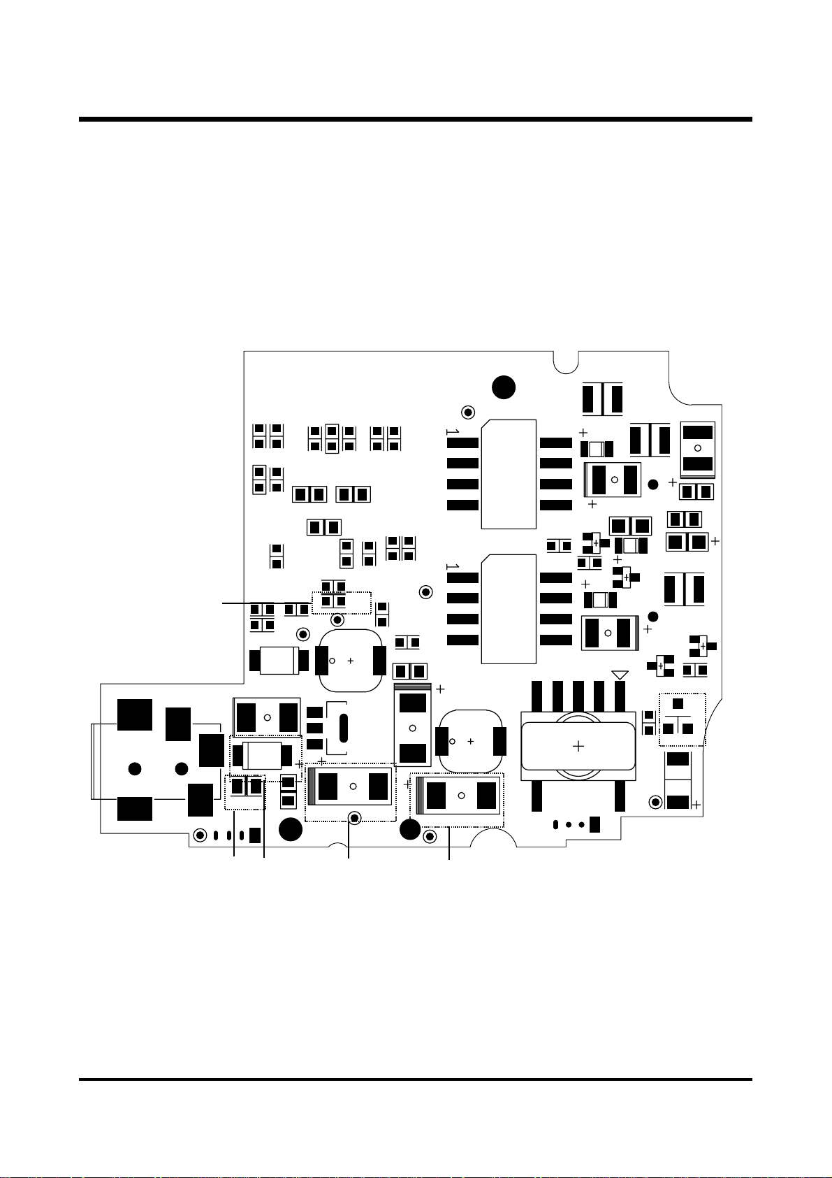
6-1. POWER Error
Lift pin 20,37,47 of U1 and
check for overcurrent with
power on.
Page 4

49
Ⅵ. TROUBLESHOOTING & MAINTENANCE
C4
Q9
Q1
J2
R210
R203
C16
C35
Q9
C15
L7
C27
R208
L3
L1
C46
Q2
C201
C11
J4
D4
D6
D1
C10
C34
D12
Q102
R201
D7
C2
D3
R51
Q1
C26
L6
C18
Q6
C4
C18
Q2
R41
Q8
C37
R44
R35
C38
C47
R52
C14
C31
R37
C40
R39
R46
R43
C39
VR1
D9
R17
R42
U3
C13
R27
R31
C30
R30
R49
R15
C33
R13
R24
R48
C32
C12
C23
L9
R10
C29
R8
C17
R7
R22
U1
R4
C9
R12
R18
C25
C103
L12
C103
J3
D9
L9
Page 5

50
Ⅵ. TROUBLESHOOTING & MAINTENANCE
Replace C44
YES
Replace Q3
YES
NO
NO
NONO
NO
NO
NO
NO
NO
Connect R26 with
VCC(F2,C52) and check for
overcurrent with power on.
Connect R25 with
VCC(F2,C52) and check for
overcurrent with power on.
Check C44
for short.
Check if
D8
damaged.
Detach Q2 and check if there is
short between Collector & Base,
Collector & Emiter, Emiter & Base
Detach D4, D6, D7 and check
the board for short.
Detach C19
and check the
board for short
Replace
C19
Detach Q3 and check
if short between
Collector & Base,
Collector & Emiter,
Emiter & Base
Replace
U1
Replace C44
Replace
Q2
YES
YES YES
YES
YES
NO
Solder D4 and then check the
board for short
Detach C16
and check the
board for short
Replace
C16
YES
YES
NO
Detach C15
and check the
board for short
Replace
C15
Check Pin
11,13,15 of J2
YES
NO
Solder D6 and then check the
board for short
Detach C27
and check the
board for short
Replace
C27
YES
YES
NO
Detach C26
and check the
board for short
Replace
C26
Check Pin
13,15,17 of J2
YES
NO
Detach L5 and
check the
board for short
Replace
C20
YES
NO
Check Pin 3,5
of J2 for short
Replace
U1
YES
NO
After touch up J2
connector and check
the board for short
Replace
U1
YES
Page 6
51
Ⅵ. TROUBLESHOOTING & MAINTENANCE
BAT-
R26
J5
L11
F2
R2
C1
R16
R14
R21
D8
C51
R6
R5
C22
C28
R9
3.3V
Q3
D10
R23
C52
C24
L4
T2
R209
Q203
R207
U2
C6
D5
C19
C3
ZD1
Q202
D2
LCD_BL
R28
C41
R25
R26
T-WAE
7V_TP
R29
C36
R38
L8
C44
R32
R34
LCD_TP
R40
R36
CCD_TP
R33
T1
C45
L10
C50
LCD_7V
L5
R50
C8
Q204
Q201
C101
C20
C21
C5
L2
R206
Q7
Q7
F2
C51
C52 C50
Page 7

52
Ⅵ. TROUBLESHOOTING & MAINTENANCE
Solder D7 and then check the
board for short
Detach C35
and check the
board for short
Replace
C35
Detach Q2 and check if short
between Collector & Base,
Collector & Emiter, Emiter & Base
Connect R31 with VCC(F2,C52)
and check for overcurrent with
power on.
Replace
Q1
YES
Detach D1,D3 and
check the board for
short
Detach C5 and check the
board for short
Replace
C5
YES
Solder D1 and check
the board for short
YES
Solder D3 and check
the board for short
Check C10,11 broken and
short
Check Pin 23,25,27 of J2
YES
Check
C2,C3,C201,R207,208,209,
Q202,Q203 parts and if
short in cold soldered.
Replace
abnormal
parts and
remove
short
Replace
abnormal
parts and
remove
short
Remove
short
Detach L2 and check the
board for short
Replace
C6
YES
Detach Pin 27,29 of J2.
Replace
U1
YES
YES
After touch up connector
and check the board for
Replace
U1
NO
NO
NO
NO
NO
NO
NO
NO
NO
NO
Detach C34
and check the
board for short
Replace
C34
Check Pin
4,6,8 of J2
YES
YES
Check Pin
16,18,20 of J2
YES
YES
YES
YES
YES
YES
Page 8

53
Ⅵ. TROUBLESHOOTING & MAINTENANCE
3.3V is input at
V2 Test Port
When mounting battery or
DC adaptor, the voltage is
changed from L to H in the
output end(#3) of
Reset IC(U1)
If pin #9 and #10 of
connector J1 being short
more than 0.5 seconds,
Beep(Buzzer-1) sound
occurred.
Short at V2 T.P and G1 T.P
terminals
Visual check if the parts
are soldered properly.
Y : Replace SUB board
N : Replace and check the
part
Replace SUB board
Replace J2 connector parts
Replace Reset IC(U1)
Resolder Reset IC(U1)
Replace Oscillator(Y1)
Replace Buzzer
Resolder CPU(U2)Pin #38
Resolder J1 Pin #9, #10
Resolder R3,D1,C10
Resolder CPU(U2) Pin #49
Resolder BZ+, BZ- L/W
Resolder R2
Resolder and check CPU(U2)
Pin #70, #71 Oscillator(Y1)
YES
YES
YES
YES
YES
YES
NO
NO
NO
NO
NO NO
NO
NO
NO
YES
YES
YES
6-2. SUB PCB Error
Good soldering of J2
connector PIN #4, #6
Good soldering Reset IC(U1)
CPU(U2) #38 Pin is
changed from H to L level.
Oscillating wave form is
measured at CPU(U2)Pin
#70 and #71
Oscillating wave of about
100ms is output to
CPU(U2)Pin #49 (f=4kHz)
Page 9
54
Ⅵ. TROUBLESHOOTING & MAINTENANCE
“boot”display goes on and
off(2Hz) in Status LCD
“boot”display disappears
within 5 seconds
During booting, green LED
next to finder goes on and
off
LCD driving power is normal.
T.P terminal of T1 :about 3.0V
T.P terminal of T2:about 2.0V
T.P terminal of T3:about 1.0V
“Err”is displayed in
Status LCD
Connector(J2)Pin #14 is
measured as “H”
Connector(J2)Pin #18 is
measured as “H”
Connector(J2)Pin #10 is
measured as “L”
Connector(J2)Pin #15 is
changed to “L”to “H”after
25ms
3.3V power supplied at
ASL+ terminal
Check if 3.3V output at
CPU(U2) Pin #25 and then
resolder it
Resolder R10/R5/R7/R9
Resolder
CPU(U2)#26/#27/#28
Resolder CPU(U2) Pin #10
~#24, clean and check it
Check of the contacts of
mode dial distorted
clean the mode dial pattern
Resolder CPU(U2) Pin #47
Resolder connector(J2) Pin
#14
Resolder CPU(U2)Pin #75
Resolder connector(J2)Pin
#18
Resolder CPU(U2)Pin #53
Resolder connector(J2)Pin
#10
Resolder CPU(U2)Pin #50
Resolder connector(J2)Pin
#15
Resolder SUB PCB
(Jump wire) or Resolder
SUB PCB Ass’y
See 5-3. Main PCB repair
Resolder LED FPCB
YES
YES
YES
YES
NO NO
NO
NO
NO
NO
NO
NO
NO
NO
YES
YES
YES
YES
YES
YES
NO
Page 10

55
Ⅵ. TROUBLESHOOTING & MAINTENANCE
Cst5
280V
U1
J2
#14->H
#18->H
#10->L
#15->25ms
L->H
V2 Test point
G1 Test point
U2
#25=3.3V
#38 H->L
#70,71
#49 100ms
#58=About 3V
T1 = 3.0V
T2 = 2.0V
T3 = 1.0V
ASL=3.3V
T6=
8kHz
STL=
4kHz
STL=
4kHz
#49 =
#70,71 =
Page 11

56
Ⅵ. TROUBLESHOOTING & MAINTENANCE
Oscillating wave form is
measured in the end T.P of
T6
Resolder CPU(U2)Pin #39 to
#41 and connector(J2)Pin
#7/#9/#11
Oscillating wave output in
AFL-terminal(f=4Hz)
Resolder CPU(U2)Pin #35
Resolder R4/R6
See 5-3. Repairing
Main PCB
Resolder AF LED(LED FPCB)
YES
YES
YES
YES
YES
YES
YES
NO
NO
NO
NO
NO
NO
NO
NO
NO
Battery Half mark goes on
and off(2Hz)
The voltage of about 3V is
measured in CPU(U2)Pin
#58
Resolder CPU(U2) Pin
: #58/#65/#64
Resolder connector (J2)Pin
#2. Resolder C6/C7
Whill charging flash,
red LED next to finder
goes on and off(8Hz)
Oscillating wave is output
in STL-terminal (f=8Hz)
Resolder CPU(U2) #34 Pin
Resolder R11/R18
See 5-3. Repairing
Main PCB
Resolder STB LED(LED FPCB)
NO
If controlling button and
mode dial, it operates
KEY recognition Buzzer
sound is generated.
After about 2 minutes,“E10”
will be displayed in Status
LCD
Resolder CPU(U2) Pin
: #54 to #57 Pin
: #77 to #80 Pin
Resolder U3/U4/U5/U6
Resolder CPU(U2) Pin
: #39 to #41,48 Pin
Resolder connector (J2) Pin
: #7/#9/#11/#13 Pin
Replace KEY FPCB Ass’y
NO
NO
Page 12

57
Ⅵ. TROUBLESHOOTING & MAINTENANCE
1. Check Buzzer sound
2. Check Mode Dial conversion
3. Check if the current 600mA (If error occurred, See Merr 8)
Mode Dial→MACRO→
CAMERA→PLAY→MACRO
Menu Key→Right→Left
→Down→Up→Menu Key
Status(Erase)Key
“ON”, “OFF”
Enter Key “ON”, “OFF”
LCD Key “ON”, “OFF”
Zoom Key operation
T ↔ W 2 times
1. check TV Monitor
2. Remove video cable
3.Check TFT-LCD screen
Start
Mode Dial → PLAY
Power Switch “ON”
1. Check buzzer sound(if error occurred, See Merr 1)
2. Check of the current being 500mA(If error occurred, See Merr 2)
1. Check if Zoom operation Checking current being 800mA.
(if error occurred, See Merr 9)
1. Check TFT-LCD User I/F (If error occurred, See Merr 10)
1. Check TFT-LCD backlight control terminal
(If error occurred, See Merr 11)
Setting in TFT-LCD or TN-LCD
1. Check SUB↔HOST micom communication
(TN-LCD “BOOT”display continuously →
See
Merr 3)
2. Check HOST↔ZORAN micom communication
(Green LED ON continuously →
See
Merr 4)
3. Check ZORAN Card related I/F (“Card ERROR”display →
See
Merr 5)
4. Check Video ZORAN related (No image on TV monitor →
See
Merr 6)
5. Check TFT-LCD I/F related (No image on TFT-LCD →
See
Merr 7)
6-3. MAIN PCB ERROR
Fill-in flash mode setup
Page 13

58
Ⅵ. TROUBLESHOOTING & MAINTENANCE
1. check of shutter button operated on the 1st stage and the current being 1.0A
(If Error occurred, → See Merr 12)
2. check of shutter button operated on the 2nd stage and the current being 1.1A
(If Error occurred,→ See Merr 13)
3. Check of strobo operated and illuminated (If Error occurred,→ SeeMerr 14)
4. Check for photo Sensor Circuit and photo sensor open/close.
(If Error occurred,→ See Merr 15)
Mode Dial→MACRO→
shutter button 1st stage→
2nd stage→Photographing
(with photo sensor)
Shutter button 1st stage→
2nd stage→Photographing
(With photo sensor open)
Mode Dial→PLAY
Check screen TFT-LCD
Mode Dial→PLAY
Check TFT-LCD screen
When inserting and
removing CF Card 2 Times,
check “Card Error”
Power switch→“OFF”
End
1. Check Card recognition, if “card Error”displayed
(If error occurred, See Merr 5)
1. Check PR circuit, If TN LCD is extinguished 3 seconds of Power OFF
(If error occurred, See Merr 16)
Page 14

59
Ⅵ. TROUBLESHOOTING & MAINTENANCE
Check the mounting status
of CP 8,9,10
Check the mounting status
of CP11,Rp1,and RP2
Check if Pin J2 #4, 6,and
other pins being short.
check of Pin J3 #2 and
other pins being short.
UP3 #3=3.3V? CP11-1=3.3V?
Buzzer sound can not be
heard.
Check the SUB PCB
power,VCC3-KA is 3.3V?
Battery check power,
BAT-CHK is 2.7V?
MAIN Power,
+3.3VCC(MAIN)=3.3V?
MERR1
YES YES
NO NO
Check if Pin J3 #20, 22, 24
and other pins being short.
Check if pin J3 #20, 22, 24
and other pins being short.
Check if J3 pin #19, 21, 23
and other pins being short.
UP3 #2=5.6V? UP4 #3=5.6V? UP4 #2=3.3V?
Page 15

60
Ⅵ. TROUBLESHOOTING & MAINTENANCE
J3
UP4
#2=3.3V
#3=5.6V
RP1,2
CP8,9,10
CP11=3.3V
UP3
#2=5.6V
#3=3.3V
Page 16

61
Ⅵ. TROUBLESHOOTING & MAINTENANCE
The current will be over 5oomA
in Play Mode, When turn”ON”.
There is abnormal in
Zoom or Focus drive.
Check if U16 #34 to #40
being short
MERR2
There is abnormal in Focus.
NO
Check if J4 pin 2, 4, and other
pins being short.
Check if U16 #52 to 55, 42,
and 57 being short.
Check if J4 64, 66, 68, 70 and
other pins being short.
Check if J4 pin 6, 8, 10, 12
and other pins being short.
Check if J4 1, 3 and other
pins being short.
YES
Page 17

62
Ⅵ. TROUBLESHOOTING & MAINTENANCE
U16 short check
#34~40
#52~55
#42,57
J1
Page 18

63
Ⅵ. TROUBLESHOOTING & MAINTENANCE
“boot”continues to be
displayed in TN-LCD.
SUB ↔ Hist micom
communication error check
Check if “Mreset”signal of
TP being output when turn
on.
Check if Xrst1 signal of TP
being output.
Check if U18, 19, 21 parts
being short(XHCS of TP)
Check if SL1, SO1, SCK1,
KEY_BR signal line being
short
Check if U1 pin 144 and
other pins being short.
Check if RA33 and RA32
signal line being short.
Check if U16 pin 27 to 30
and other pins being
short(signal line A8~A10)
Check if J2 pin 7, 9, 11, 13
being short.
Check if U1 pin 130, 131,
134 to 137, 139, 140, and
other pins being short.
Check if U16 pin 11 to 13,
and 65 being short.
Check if U16
pin
40, 41,
43,61and other pins being
short (singnal line XHRD,
XHWR, XHAS, XHIRQ).
Check if U1 pin 145 to
147, 127, 139, 140, and
other pins being short.
Check the
EEPROM
soldering status.
If “boot”continues
to be displayed
in TN-LCD
Check the soldering status
of U4, RA10, U1, pin #204
and 205.
MERR3,4
See 6-10, Card Error.
MERR5
See 6-6, TV Output Error
MERR6
See 6-5, LCD Image Error
MERR7
YES
NO
Page 19

64
Ⅵ. TROUBLESHOOTING & MAINTENANCE
Check the RTC circuit.
VDD3-RTC voltage > 1.8V?
Remove card and check if
“boot”completed.
Remove card after 1 minute,
check if “boot”completed.
See 6-10. Card Error.
Check for TFT-LCD
image
Check for TV output
screen.
See error 6-6. TV output
Error.
See 6-5. image Error.
Check if SAMSUNG logo seen
with green LED flickered.
Check if U20, U16 PIN #15
and other parts being short.
Check the Diode(DP1)
polarity and resistor(R70),
BTP1 value check.
Check if VCC3-HOST is 3.3V
at the point DP1-Anode
Check if green LED being Off.
YES
YES
NO
NO
NO
NO
End
YES
YES
YES
YES
YES
NO
Resoldering
and replace.
Page 20

65
Ⅵ. TROUBLESHOOTING & MAINTENANCE
RA32
RA33
U16 short check
#11~13,15, 27~30
#40,41,43,61,65
J1
RTC >1.8V
U20 #15
Short check
U4
RA10
Page 21

66
Ⅵ. TROUBLESHOOTING & MAINTENANCE
k
U1 Short check
#145~147,127,139,140,144
U18,19,21
R70
DP1 Anode=3.3V
J2 Short chec
#7, 9, 11, 13
Page 22

67
Ⅵ. TROUBLESHOOTING & MAINTENANCE
See 6-4. CAMERA Mode
Error
MERR8
Check if the current being
800mA during Zoom Key
operation
MERR9
Check if J4 #2,4,64,66,68,
70, pin and other pins
being short.
Check if RA34, U16 #36 to
39 being short (EN0~EN3)
Check if U16 #34, 35 being
short (ZIN0, ZIN1)
See 6-2. SUB PCB error.
MERR10
TFT-LCD “ON-OFF”
does not work.
MERR11
Check if J3 #28, J2 #16,
and other pins being short.
Check if the current being
1.0A instantaneously in the
1st stage of shutter button.
MERR12
Focus motor control signal
line error.
See MERR2.
Check if the current being
1.0A instantaneously in the
2nd stage of shutter button.
MERR13
Error occurred in shutter
control signal AE-METER
control signal line.
Check if J4 #5, 7, 9, 11,
and other pins being short.
Check if U1-208, U16-62, U16
48 to 51, and other pins
being short.
PR circuit check.
MERR16
TN-LCD turns off after 3
seconds in power OFF.
Check for QM1, 2, DM1,
RM1, 2 parts and short.
Check if U16 #31, 32, R49
and other pins being short.
Check for PR FPCB.
Check the strobo operation.
MERR14, 15
Check if J3 #20 to 24 and
other pins being short.
See 6-11.STROBO Error.
Check if U16 #44, 64, 76 to 80
and other pins being short.
D50 polarity check.
photo circuit check.
Page 23

68
Ⅵ. TROUBLESHOOTING & MAINTENANCE
MERR13
U1 Short check
#208
MERR11
J3 Short check
#28
MERR14,15
J3 Short check
#20~24
MERR16
R49 Check
MERR9
J4 Short check
#2,4,64,66,68,70
MERR13
J4 Short check
#5,7,9,11
MERR11
J3 Short check
#16
Page 24

69
Ⅵ. TROUBLESHOOTING & MAINTENANCE
MERR16 Check
QM1,2DM1,RM1,2
MERR14,15
D50 Check
MERR9
U16 Short check
#36~39
MERR13
U16 Short check
#2, 48~51
MERR14,15
U16 Short check
#44,64,76~80
MERR16
U16 Short check
#31,32
RA34
Page 25

70
Ⅵ. TROUBLESHOOTING & MAINTENANCE
When changing CAMERA
mode, the current goes to 0
instantaneously or system
is halted.
Check if being short between
CCD shield and other parts.
Lens body tube distortion or
damage.
Replace lens.
YES
YES
YES
YES
Focus motor sounded creaking
See 6-12. Lens Error.
YES
‘E05’message displayed
YES
Encoder contact distortion
YES
YES
YES
YES
Check the soldering of UM1
Check X1 pulse in CCD board.
Ckeck if IR14 and BD6
soldered.
Check IR14(CCLK)
Output,18MHz?
Check the voltage of IL3, IL4 are 3.3V
Check soldering state of surrounding
parts of X1 in CCD board.
Replace CCD board.
Check if connected between
JM3-FPCB and check
soldered state IJ1(CCD
board),J4(MAIN board).
NO
See 6-7 Image Error
Lens does not come out.
Zoom motor is not
initialized.
(Slants to one side,
NO
NO
NO
NO
NO
NO
NO
NO
6-4. CAMERA Mode Error
Encoder contact joint error
See 6-12. Lens Error.
Replace lens.
See 6-12. Lens Error.
YES
YES
YES
Page 26

71
Ⅵ. TROUBLESHOOTING & MAINTENANCE
IR14
BD6
IJ1
JM3
UM1
IL4
Page 27

72
Ⅵ. TROUBLESHOOTING & MAINTENANCE
See 6-9. Replay Error
See 6-3. MAIN Board Error
LCD Image Error
See the image on TV
Is the image of LCD equal
with TV screen?
Is the image good in PLAY
mode?
See 6-3. Main Board Error
See 6-7. Image Error
Resolder RL23,RL24,RL51
UL1,U1#178~180,#142 in
Main board.
Resolder UL1, JL1
U1#118~126 PIN,
and LCD circuits
See 6-1. POWER Error
YES YES
YES
NO
TV output, OK?
YES
NO
Test LCD by changing with
another. OK?
Replace LCD pannel
YES
NO
Back Light dose not turn on.
Check the connection of
BACK LIGHT connector
See 6-1. POWER Error
YES
NO
Image on LCD is white.
Check the powers of LCD
part (CL7:+5V, RL67:+15V,
DL1 CATHOD:-10V)
Check the below signals in
Main board
RL23:19KHz
RL24:73.8KHz
RL51:13.6MHz CLK
YES
YES
YES
NO
NO
NO
LCD image comes out but
not clear.
Resolder UL1#50~#60,
JL1,U1#118~#126,R41,R42,
R44~R47,R59,R60 in Main
board OK?
Replace the Main board
Replace the Main board.
NO
NO
NO
NO
NO
6-5. LCD Error
Is the image good in
CAMERA mode?
See 6-6. TV Output Error
Page 28

73
Ⅵ. TROUBLESHOOTING & MAINTENANCE
UL1 #50~#60
U1 #118~#126
RL23,24,50
RL51
U1 #178~#180
R41,42
R60
R44~47
JL1
CL7
RL67
DL1
MAIN PCB (TOP)
MAIN PCB (BOT)
Page 29

74
Ⅵ. TROUBLESHOOTING & MAINTENANCE
Image on LCD is good, but not
good on TV screen.
Image is displayed on TV Check soldering of L50 Resolder L50
YES
YES
NO
Is the image quality equal
to LCD?
NO
NO
Check the connection JACK
board
Reconnect JACK board
YES
NO
When video jack inserted,
check the U16 #47 change
‘H’to ‘L’
resolder Q3,Q4,R19. Steel
not working, replace Q3, Q4.
YES
NO
Check video output of U1 #164 Resolder U1 #164
YES
NO
U1 error Replace Main board
YES
Is the image good in PLAY
mode?
Check the connection JACK
board
Resolder the JACK board
including J5.
Reconnect JACK board.
Check the video filter
(L50 surroundings)
NO
Resolder R37, U1 #164
NO
Replace Main board
NO
Resloder the video filter
(L50,,R81,C90~C92,J5)
See 6-7. Image Error
YES
YES
YES
YES
YES
NO
NO
See 6-3. Main PCB Error
6-6. TV Output Error
See 6-9. Replay Error
Is the image good in
CAMERA mode?
Page 30

75
Ⅵ. TROUBLESHOOTING & MAINTENANCE
U1 #164
R37
C91
C92
C90
L50
R81
Page 31

76
Ⅵ. TROUBLESHOOTING & MAINTENANCE
YES
NO
Resolder IJ1, UM3 and its
surroundings
Playback image of normally
captured is good. But,
image of camera mode has
error.
Check connection between
boards
Check EEPROM data, OK? Rewrite EEPROM data
NO
Check lens operation, OK? See 6-12. Lens error
NO
CCD board change test,
OK?
Resolder U1 #182~#191, J4
See 6-3. Main Board Error
NO NO
Check the CCLK(BD6)
signal. (18MHz)
Resolder IJ1, X1, IU3, IR14, in
CCD board and J4, U1 #197
in Main board
Resolder IL3, IL4.
See 6-1. POWER Error
Check power IL3, IL4 are +5V
Replace CCD board
NO
NO
NO
NO
NO
NO
NO
NO
YES
YES
YES
YES
Check the signal in CAMERA
mode
HD(IR32):9.8KHz
VD(IR33):30Hz
Resolder IJ1, IU3 in CCD
board and J4 R103, R104, U1
#194~ #197 in Main board
Check CCD output in CCD board
Resolder IU3 and its
surroundings
NO
Replace CCD board
YES
YES
Preview image is not clear
Replace CCD board
Resolder IU3 and its
surroundings, IU2 and its
surroundings, IJ1
YES
Captured image has error
As press shutter, system
halted
YES
6-7. Image Error
YES
Replace CCD board
Resolder IU3 and its
surroundings
Replace CCD board
Page 32

77
Ⅵ. TROUBLESHOOTING & MAINTENANCE
R103,104
U1 #194~197
J4
MAIN PCB (TOP)
CCD PCB (BOT)
CCD PCB (TOP)
IL4
JM1
IR14
UM3
X1
Page 33

78
Ⅵ. TROUBLESHOOTING & MAINTENANCE
Mechanical Shutter does
not operate when press
the shutter button.
Check if connected between
JM2 CONNECTOR and
FPCB in CCD PCB ASS’Y.
Resolder JM2 or reconnect
CONNECTOR.
YES YES
NO
Resolder UM3.
YES
NO
YES
NO
See 6-10. Card error
NO
6-8. Card Recording Error
Resolder #5,7,9,11 pins of
J1.
Check if #5,7,9,11 pins of
J1 soldered in CCD PCB
ASS’Y.
Check if UM3 soldered in
CCD PCB ASS’Y.
Replace BARREL ASS’Y,
CCD PCB ASS’Y, MAIN PCB
ASS’Y one by one and
check for operation.
See MERR 13.
YES
Page 34

79
Ⅵ. TROUBLESHOOTING & MAINTENANCE
JM2
X1
J4
U16
J1
MAIN PCB (TOP)
CCD PCB (BOT)
CCD PCB (TOP)
MAIN PCB (BOT)
UM3
Page 35

80
Ⅵ. TROUBLESHOOTING & MAINTENANCE
NO
YES
The picture will not replay.
If waiting for 1 minute, the
picture appears.
Green LED goes on and off
continuously.
Image photographed in TIFF
See 6-10. CARD Error
YES
Replayed picture goes off in
the way of replaying.
YES
Moving image mark is
displayed in the upper lift
corner of picture and
replayed if pressing Enter
button.
YES YES
YES
NO
YES
Dark photographing
environment.
Brightness of image itself
too low
CCD I/F Error
COACH Processor Error
Picture photographed in
Moving image.
All of replayed picture have
abnormal colors.
YES
AWB Error
MAIN PCB U1 part Error
Picture Size Setting Error
MAIN PCB U16 part Error
NO
NO
NO
NO
NO
NO
6-9. Replay Error
Replayed picture appears
small.
Replace MAIN PCB Ass’y
Compression Error
MAIN PCB U1 part Error
Replace MAIN PCB Ass’y
For other errors
Page 36

81
Ⅵ. TROUBLESHOOTING & MAINTENANCE
Card is not
recognized.
Ckeck J1 Connector
being short.
Check the buffer
U9 and U10
being short.
Check U15 NOT
Gate being short.
Check the
resistors
RA4,RA5, and
RA35 being short.
When pressing the shutter
in Macro mode, “No Card”
is displayed.
And “Error Pos=1”is
displayed.
“Bad Format”is displayed.
Use the formatted card.
Otherwise, “Error Pos=2”is
displayed.
Card compatibility error.
After formating card,Use that.
Use the recommended card.
Remove the card and
then insert it.
Check U16 #3,
NO. 46 being
short.
SEE Card Error(Merr5).
NO
YES
NO
NO
YES
6-10. CARD Error
Check U14 NOT
Gate being short.
Check U30 OR
Gate being short.
Check R55 Gate
being short.
Check U1 Card
I/F being short.
Otherwise, “Error Pos=4”is
displayed.
When pressing the shutter
in Macro mode, “No Card”
is displayed.
When pressing the shutter
in Macro mode, “Error
Pos=2”is displayed.
NO
Page 37

82
Ⅵ. TROUBLESHOOTING & MAINTENANCE
U30
U1
R55
U13
U14
U15
R35
U9
U16
RA4
RA5
Page 38

83
Ⅵ. TROUBLESHOOTING & MAINTENANCE
NO NO
NO
NO
NO NO
NO
YES
YES
YES
YES
YES
YES
YES
Bad Charging
Is it charged during Power
On?
Flash Emitting Error
Is it luminescent in low
brightness?
“H”Supply at Qst9 Base(OSC)
“H”Supply at Qst8 Base(NEC)
Is it charged?
When Cst5 charged at
about 280V, is NEst1
illuminated?
Charging circuit and
detector of STROBO are
normal.
Check if OSC, NEC, and
NES signal lines are
connected from Main PCB to
SUB PCB normally.
Is about 200V voltage output
at Qst6 Collector?
Is “H”output at Qst6 Gate
when supplying “H”at
Rst11”
Check charging circuit
Check Qst9, Qst1, Rst4,
Qst2, Cst1, Qst3, Tat1, Rst1,
Dst1, and Dst2 for normal.
Check if not soldered, cold
soldered, and parts
damaged.
Check if IGBT being broken.
Check if Qst6 Parts being
broken. Check Rst6 for
normal.
Check TRIG Control Circuit.
Check Rst11,Rst12,Qst4,Qst5,
Rst5, Rst10,Rst13, and Ust1
for normal. Check if not
soldered, cold soldered or
parts damaged.
6-11. STROBO Error
Check charging circuit
Check Rst2, NEst1, Rst3,
Qst7, Rst9, Qst8, and Cst2
for normal.
Check if not soldered, cold
soldered, and parts
damaged.
When NEst1 illuminated,is
about 0.7V output at NES
terminal?
Page 39

84
Ⅵ. TROUBLESHOOTING & MAINTENANCE
NO
NO
NO
NO
YES
YES
YES
YES
YES
YES
Abnormal Flash Emitting.
The intensity of illumination
is different in the same
conditions.
Check Photo Sensor circuit.
Is the waveform of PWM
output in S1?
Dose the Analog
voltage(different according
to Zoom position) appear at
#3 of Uef1 in S1?
Flash Emitting circuit of
STROBO is normal. Check if
TRIG and TRIG OFF signal
lines are connected from
Main PCB to SUB PCB
properly.
Check if the Photo Sensor,
Main Capacitor, and XETube are soldered and J2
connector is connected.
Check if Qef5, and #44 of
U16 are connected.
When supplying “H”to
Rst11, is Qst6 Collector set
to “L”?
Check TRIG Circuit.
Check Cst3, Cst4, Rst7, Rst8,
Tst2, XE-Tube, Lead
Wire for normal. Check if not
soldered, cold soldered or
parts damaged.
Abnormal Flash Emitting.
Always Full/Low
luminescence.
Check if Qef1, Qef5, Ref3,
Ref4, Ref5, Cef5,and Cef6
are not soldered, cold
soldered, and parts
damaged.
Page 40

85
Ⅵ. TROUBLESHOOTING & MAINTENANCE
REF2
DEF2
QEF3
QEF2
UEF1
QEF4
REF1
MAIN PCB (BOT)
SUB PCB
Qst6
B
C
G
NEst1
Rst11
Cst5
280V
C
Qst9
BE
J2
Page 41

86
Ⅵ. TROUBLESHOOTING & MAINTENANCE
NO
YES
When setting FA-START
terminal to “H”, is #1 of
Uef1 set to “L”?
NO
YES
When luminescent
photographing in the range
of about 20cm, is FA-END
rerminal set to “L”within
100us?
Check if Uef1, Ref2, Def2,
and photo Sensor are not
soldered, cold soldered, and
parts damaged.
Check if Qef4 is not
soldered, cold soldered, and
parts damaged.
Check if Ref1, Qef3, and
Qef2 are not soldered, cold
soldered, and parts
damaged.
Page 42

87
Ⅵ. TROUBLESHOOTING & MAINTENANCE
Zoom does not operate.
AF does not operate.
During operation of ZOOM
Key, buzzer does not ring.
See 6-2. (KEY IN error)
YES YES
NO
NO
Check if DC Motor being
supplied with power in
Barrel Ass’y.
Resolder DC Motor.
YES
NO
Check if UM1 being soldered
in CCD PCB Ass’y.
YES
NO
YES
NO
YES
Check if UM2 is soldered in
CCD PCB Ass’y.
Resolder UM2.
YES
YES
NO
NO
NO
Resolder U16.
Replace Barrel Ass’y, CCD
PCB Ass’y, MAIN PCB Ass’y
one by one and check for
each operation.
YES
NO
6-12. LENS Error
Check if J1 being soldered
in CCD PCB Ass’y.
Check if J4 being soldered
in MAIN PCB Ass’y.
Check if U16 being soldered
in MAIN PCB Ass’y.
Resolder UM1.
Resolder J1.
Resolder J4.
YES
Check if JM1 Connector and
FPCB are connected in CCD
PCB Ass’y.
Resolder JM1 or reconnect
the connector.
Page 43

88
Ⅵ. TROUBLESHOOTING & MAINTENANCE
NO
Shutter does not operate.
Check if J1 being soldered
in CCD PCB Ass’y.
Resolder J1.
YES
NO
YES
NO
YES
YES
See 6-8.(Card Recording Error)
Check if J4 being soldered
in MAIN PCB Ass’y.
Check if U16 being soldered
in MAIN PCB Ass’y.
Resolder J4.
Resolder U16.
Replace Barrel Ass’y, CCD
PCB Ass’y, Main PCB Ass’y
one by one and check for
each operation.
Page 44

89
Ⅵ. TROUBLESHOOTING & MAINTENANCE
Is there installation CD in
CD-Rom Drive?
Installation of Serial
TWAIN/ Serial
Direct/USB Direct.
Insert CD.
YES
YES
Is Autorun screen displayed?
Click the program to install.
Installation is completed.
Execute “SAMSUNG.EXE”
from CD-ROM Drive root
directory.
Open Window Explorer,
select the program folder to
install from CD-ROM Drive
directory, and click
“setup.exe”in that folder.
YES
NO
NO NO
6-13. Program Installation Error
1) Installation of Serial TWAIN/Serial Direct/USB Direct
Page 45

90
Ⅵ. TROUBLESHOOTING & MAINTENANCE
Is there USB port in PC? UPrepare PC with USB port.
After PC rebooting,
install again.
NO
NO
NO
NO
NO
YES
(Add New Hardware
Wizard) appears.
Check if there is
“Samsung Digimax
210SE Camera”i n
Controller→System→
DeviceManager→Imaging
Device.
Is there (Unknown
device) in Controller
P→System→Device
Manager?
Remove (Unknown
device), perform PC
rebooting and then
install again.
NO NO
YES
NO
Is the driver to
install designated
with CD-ROM drive?
Check if there is ? mark on
“Samsung Digimax 210SE
Camera”in Controller
→System→Device
Manager→Imaging Device
Driver has been
already installed.
NO
YES
Check if Window OS being 98 or later Install Window 98 or later.
YES
YES
YES
Is the mode of camera set to PC mode?
Change the mode of camera to PC mode.
Does the camera turn on? Turn “ON”the camera.
YES
Is there installation
CD in CD-ROM drive?
Insert the installation
CD into CD-ROM drive.
NO
NO
YES
YES
YES
YES
NO
Necessary files are
copied automatically.
Installation is
completed.
Select “Samsung Digimax
210SE Camera”in
Control Panel→System→
Device Manager→Imaging
Device and then press
「Remove」button
Is there 「Samsung
TechwinD210SE.inf」in
「Windows/inf/other」
folder?
Remove
(SamsungTechwinD210
SE.inf)
After PC
rebooting, install
again.
NO
YES
YES
Are the Camera and PC connected
with USB cable?
Connect the camera and PC
using USB cable.
2) Installation of USB TWAIN
YES
YES
Is the driver to
install selected as
D210SE.inf?
Page 46

91
Ⅵ. TROUBLESHOOTING & MAINTENANCE
6-14. USB Error
Check lf the both edges of MAIN PCB R8 being 12MHz.
Check if J1 being soldered or short in JACK PCB.
Check if being soldered L1 through L4 in JACK PCB.
Check #2, #4 and #6 of J2 being soldered in JACK PCB.
Connecting USB cable with PC, make sure that R51 and
Q10
Check #2, #4 and #6 of J5 being soldered in MAIN PCB.
Check R3, R5, C2 and C5 for capacity and connection in
MAIN PCB.
Check if #238 and #239 of U1 being short from the
surrounding terminal in MAIN PCB.
Page 47

92
Ⅵ. TROUBLESHOOTING & MAINTENANCE
R8
J1
R3,5
C2
Q10
R51
C5
J5
Page 48

93
Ⅵ. TROUBLESHOOTING & MAINTENANCE
6-15. SERIAL Error
Check if the both edges of MAIN PCB R8 being 12MHz.
Check #1 and #3 of J5 being soldered in MAIN PCB
Check U3, U5, U31 and the surreonding R(9,10,12, 13, 14,
65, 110, 11, 112, 113) and C(5, 6, 25, 29, 30, 32, 131) for
capacity and connection in MAIN PCB.
Check if #224 and #245 of U1 being short in MAIN PCB.
J1
J2
L1~L4
 Loading...