

Page 1
14
ⅢⅢ.. EEXXPPLLOODDEEDD VVIIEEWWSS AANNDD PPAARRTTSS LLIISSTT
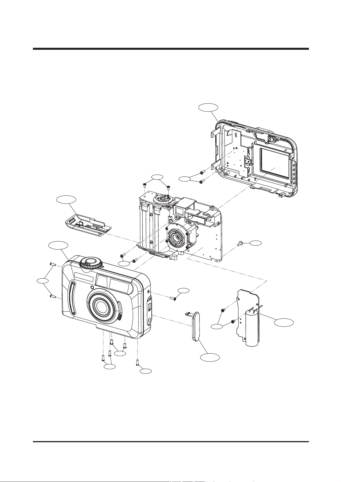
11.. BBOODD YY AASS SSEEMMBBLL YY ((11//22))
1-2
1-10
1-1
1-3
SAMSUNG
1-7
1-8
1-9
1-7
1-8
1-4
1-5
1-10
1-12
1-6
1-11
Page 2

15
ⅢⅢ .. EEXX PP LL OO DDEEDD VVIIEE WWSS AA NN DD PPAA RRTT SS LL II SSTT
▶▶
PARTS LIST
1-1 9007-1855-01A FRONT COVER ASS'Y ( DIGIMAX 201) 1
9007-1856-01A FRONT COVER ASS'Y (KENOX DIGIMAX 201) 1
1-2 9007-1857-01A BACK COVER ASS'Y 1
1-3 9007-1858-01A BATTERY COVER ASS'Y 1
1-4 6003-0386-01A SCREW 1
1-5 9008-0587-01A FL SMD ASS 'Y 1
1-6 7309-0390-01A USB COVER 1
1-7 6003-0387-01A SCREW 4
1-8 6003-0388-01A SCREW 4
1-9 6003-0389-01A SCREW 1
1-10 6003-0390-01A SCREW 4
1-11 6003-0391-01A SCREW 1
1-12 6003-0392-01A SCREW 2
Fig.No. Parts No. Parts Name Q'ty Remarks
Page 3
16
2-1
2-2
2-6
2-5
2-4
2-3
2-7
2-8
2-10
2-9
2-14
2-15
2-18
2-16
2-17
2-21
2-19
2-20
2-11
2-13
2-11
2-12
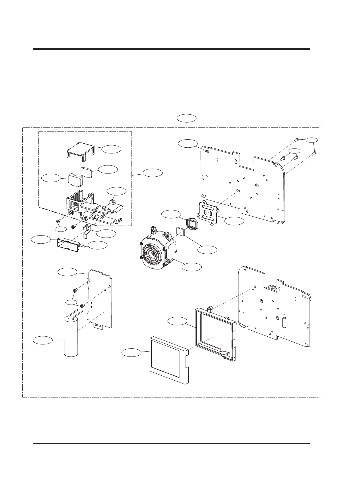
22.. BBOODD YY AASS SS EEMMBBLL YY ((22//22))
ⅢⅢ .. EEXX PP LL OO DDEEDD VVIIEE WWSS AA NN DD PPAA RRTT SS LL II SSTT
Page 4

17
▶▶
PARTS LIST
ⅢⅢ .. EEXX PP LL OO DDEEDD VVIIEE WWSS AA NN DD PPAA RRTT SS LL II SSTT
2-1 9008-0588-01A MAIN BOARD ASS'Y 1
2-2 9008-0589-01A MAIN BOARD SMD ASS'Y 1
2-3 70 11-0435-01A CCD PLATE 1
2-4 7309-0391-01A CCD RUBBER SILICON 1
2-5 6701-0085-01A LPFT 1
2-6 9002-1142-01A LENS ASS'Y 1
2-7 9008-0590-01A FL BOARD ASS'Y 1
2-8 2401-0074-01A MAIN CONDENSER 1
2-9 7217-2731-01A TFT LCD HOLDER 1
2-10 9008-0591-01A TFT LCD ASS'Y 1
2-11 6003-0387-01A SCREW 4
2-12 6003-0394-01A SCREW 2
2-13 6003-0388-01A SCREW 2
2-14 06 11-0032-01A FLASH TUBE XE 1
2-15 7217-2732-01A VF COVER 1
2-16 67 11-0494-01A VF GLASS-2 1
2-17 67 11-0495-01A VF GLASS-1 1
2-18 7217-2733-01A VF FLASH HOLDER 1
2-19 70 11-0436-01A FLASH CONDUCTOR 1
2-20 70 11-0437-01A FLASH REFLECTOR 1
2-21 9003-0197-01A FINDER ASS'Y 1
Fig.No. Parts No. Parts Name Q'ty Remarks
Page 5
18
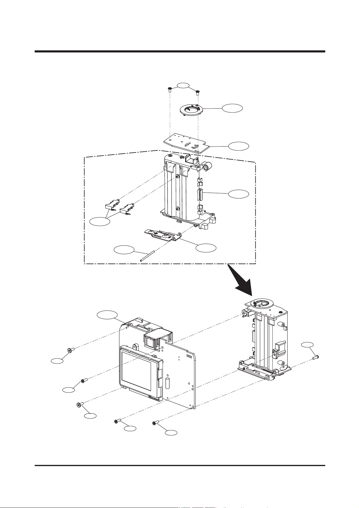
33.. SSHHUU TTTTEERR BBOOAARRDD && BBAA TTTTEERRYY BB OO XX AASSSSEEMMBB LLYY
ⅢⅢ .. EEXX PP LL OO DDEEDD VVIIEE WWSS AA NN DD PPAA RRTT SS LL II SSTT
3-7
3-3
3-2
3-1
3-8
3-9
3-6
3-7
3-5
3-4
3-11
3-8
3-10
3-9
Page 6

19
▶▶
PARTS LIST
ⅢⅢ .. EEXX PP LL OO DDEEDD VVIIEE WWSS AA NN DD PPAA RRTT SS LL II SSTT
3-1 7217-2734-01A BATTERY B O X 1
3-2 9005-0170-01A SHUTTER BOARD ASS'Y 1
3-3 9002-1144-01A FUNCTION CONDUCTION RING ASS'Y 1
3-4 70 11-0438-01A B ATTERY CONT ACT 1
3-5 74 11-0972-01A B ATTERY CONT ACT AXLE 1
3-6 70 11-0439-01A UPPER BATTERY SHEET 2
3-7 9008-0592-01A MAIN BOARD ASS'Y 1
3-8 6003-0396-01A SCREW 2
3-9 6003-0397-01A SCREW 2
3-10 6003-0387-01A SCREW 1
3-11 6003-0390-01A SCREW 1
Fig.No. Parts No. Parts Name Q'ty Remarks
Page 7

20
4-3
4-5
4-4
4-2
4-6
4-1
4-7
4-8
4-11
4-9
4-12
4-13
4-14
4-18
4-17
4-15
4-16
4-10
4-19
4-20
4-23
4-24
4-21
4-23
4-23
4-24
4-25
4-22
ⅢⅢ .. EEXX PP LL OO DDEEDD VVIIEE WWSS AA NN DD PPAA RRTT SS LL II SSTT
44.. FF RROONN TT CCOOVV EE RR AASSSSEEMMBB LLYY
Page 8

21
ⅢⅢ .. EEXX PP LL OO DDEEDD VVIIEE WWSS AA NN DD PPAA RRTT SS LL II SSTT
▶▶
PARTS LIST
4-1 9007-1855-01A FRONT COVER ASS'Y-DIGIMAX 201 1
9007-1856-01A FRONT COVER ASS'Y-KENOX DIGIMAX 201 1
4-2 7217-2735-01A FRONT COVER-DIGIMAX 201 1
7217-2736-01A FRONT COVER-KENOX DIGIMAX 201 1
4-3 7217-2737-01A RELEASE BUTTON 1
4-4 7204-0158-01A ROTATE TR AY 1
4-5 6107-0525-01A SHUTTER SPRING 1
4-6 7217-2738-01A NAME P ANEL 1
4-7 7204-0159-01A HANDLE 1
4-8 7217-2747-01A FLASH ACRY 1 1
4-9 7212-1714-01A LENS GLASS 1
4-10 7217-2739-01A USB COVER 1
4-11 7309-0390-01A NAME PLATE 1
4-12 7212-1715-01A LENS MODE HOLDER 1
4-13 7217-2750-01A LENS MODE 1
4-14 7217-2748-01A SELF TIME ACRY 1 1
4-15 74 11-0973-01A STRAP HOLE 1
4-16 7217-2740-01A MODE DUAL MYLAR 1
4-17 7017-0364-01A DIAL MODE SLR 1
4-18 7217-2749-01A FOOT ST AND HOLDER 1
4-19 7017-0365-01A DIAL CLICK UP 2
4-20 7017-0366-01A DIAL CLICK 2
4-21 7012-0754-01A E RING 1
4-22 6003-0388-01A SCREW 2
4-23 6003-0401-01A SCREW 3
4-24 6003-0387-01A SCREW 2
Fig.No. Parts No. Parts Name Q'ty Remarks
Page 9

22
ⅢⅢ .. EEXX PP LL OO DDEEDD VVIIEE WWSS AA NN DD PPAA RRTT SS LL II SSTT
55.. BBAACCKK CCOOVV EERR AASSSSEEMMBB LLYY
5-12
5-6
5-7
5-1
5-2
5-3
5-4
5-5
5-13
5-9
5-8
5-11
5-10
Page 10

23
ⅢⅢ .. EEXX PP LL OO DDEEDD VVIIEE WWSS AA NN DD PPAA RRTT SS LL II SSTT
▶▶
PARTS LIST
5-1 9008-1857-01A BACK COVER ASS'Y 1
5-2 7217-2741-01A BACK COVER 1
5-3 7217-2742-01A VF BACK ACRY 1 1
5-4 7217-2743-01A BACK LED ACRY 1 1
5-5 7217-2744-01A MENU KEY 1
5-6 7017-0367-01A METAL MODE SET 1
5-7 9008-0593-01A KEY BOARD ASS'Y 1
5-8 0704-0089-01A LCD PANEL 1
5-9 7217-2745-01A POWER KEY 1
5-10 7217-2746-01A SEL KEY 1
5-11 6107-0526-01A SHUTTER SPRING 1
5-12 6003-0387-01A SCREW 2
5-13 7409-1361-01A SPONGE 1
Fig.No. Parts No. Parts Name Q'ty Remarks
Page 11

24
66.. PPAACCKKIINNGG IITTEEMM
6-1
6-2
6-3
6-4
6-6
6-7
6-9
6-8
6-5
6-14
6-10
6-11
6-13
6-12
ⅢⅢ .. EEXX PP LL OO DDEEDD VVIIEE WWSS AA NN DD PPAA RRTT SS LL II SSTT
Page 12

25
▶▶
PARTS LIST
Fig.No. Parts No. Parts Name Q'tY Remarks
6-1 7409-1306-01A FCC LABEL(MADE IN CHINA) 1
7409-1307-01A FCC LABEL(MADE BY SAMSUNG) 1
7409-1308-01A MIC LABEL_KENOX D 201 1
6-2 6804-0446-01A PRODUCT STICKER 1
6-3 P960-2240-01A PE BAG(FOR CAMERA) 1
6-4 6904-0240-01A POUCH 1
6-5 6901-1705-01A G/T BOX_KENOX_D 201_KOR 1
6901-1706-01A G/T BOX_DIGIMAX 201 1
6901-1707-01A G/T BOX_USA/CAN 1
6-6 4609-0042-01A DRIVER + MGI PHOTOSUITE(E/F/G/S/I/DUT/P) 1
4609-0043-01A DRIVER + MGI PHOTOSUITE(E/JPN/T.C/S.C/KOR) 1
6-7 6807-0026-01E WARRANTY CARD_KOR 1
6807-0030-03O WARRANTY CARD 1
6807-0038-02D WARRANTY CARD_UK 1
6807-0109-02B WARRANTY CARD_RUS 1
6807-0113-01A WARRANTY CARD_CHI 1
6807-0095-02D CARD PRODUCT_MEXICO 1
6-8 6806-1399-01A USER MANUAL_KENOX_D 201 1
6806-1400-01A USER MANUAL_ENG 1
6806-1401-01A USER MANUAL_GER 1
6806-1402-01A USER MANUAL_FRA 1
6806-1403-01A USER MANUAL_SPA 1
6806-1404-01A USER MANUAL_ITA 1
6806-1405-01A USER MANUAL_CHI(T) 1
6806-1406-01A USER MANUAL_DUT 1
6806-1407-01A USER MANUAL_POR 1
6806-1408-01A USER MANUAL_SWE 1
6806-1409-01A USER MANUAL_DEN 1
6806-1410-01A USER MANUAL_FIN 1
6806-1411-01A USER MANUAL_RUS 1
6806-1412-01A USER MANUAL_CHI(S) 1
6-9 6909-0116-01A PE BAG(FOR ACCESSORY) 1
6-10 3801-0028-01A USB CABLE 1
6-11 7409-1217-01A STRAP 1
6-12 4602-0004-01A SD CARD_16MB 1
4602-0005-01A SD CARD_32MB 1
6-13 4301-0018-01A BATTERY 1
6-14 6901-1708-01A INNER PAD 1
6806-1426-01A QUICK GUIDE_KOR 1
6807-0110-01A CARD_NETHERLAND(DIGITAL CAMERA) 1
6807-0108-01A U.K_VOUCHER 1
6804-0063-01G A/S STICKER_KOR 1
6804-0088-01A SECURITY STICKER_USA 1
6804-0377-01A TECH/SUPPORT(DSC_USA) 1
7409-0637-01A SAFETY_RUSSIA 1
ⅢⅢ .. EEXX PP LL OO DDEEDD VVIIEE WWSS AA NN DD PPAA RRTT SS LL II SSTT
Page 13

26
7. INITIAL PARTS LIST
ⅢⅢ .. EEXX PP LL OO DDEEDD VVIIEE WWSS AA NN DD PPAA RRTT SS LL II SSTT
NO PARTS NO. PARTS NAME SPEC PAGE
1 9007-1855-01A FRONT COVER ASS'Y KENOX DIGIMAX 201 14
2 9007-1856-01A FRONT COVER ASS'Y DIGIMAX 201 14
3 9007-1857-01A BACK COVER ASS'Y 14
4 9007-1858-01A BATTERY COVER ASS'Y 14
5 9002-1144-01A FUNCTION COUNDUCTION RING ASS'Y 18
6 7011-0439-01A UPPER BATTERY SHEET 18
7 7011-0438-01A BATTERY CONTACT 18
8 7217-2747-01A FLASH ACRYL 20
9 0704-0089-01A LCD PANEL ASS'Y 22
10 7217-2746-01A SELECT KEY 22
11 3722-0012-01A DC JACK 34
12 3722-0011-01A USB JACK 34
13 2604-0018-01A TRIGGER COIL 36
14 7217-2749-01A FOOT STAND HOLDER 20
15 7212-1715-01A LENS MODE HOLDER 20
16 7204-0158-01A ROTATE TRAY 20
17 7217-2737-01A RELEASE BUTTON 20
18 6107-0525-01A SHUTTER SPRING 20
19 7217-2750-01A LENS MODE 20
20 0611-0032-01A FLASH TUBE XE 16
21 1407-0007-01A IGBT 36
22 7309-0390-01A USB COVER 14
23 9008-0587-01A FL BOARD ASS'Y 36
24 9005-0170-01A SHUTTER BOARD ASS'Y 38
25 9008-0593-01A KEY BOARD ASS'Y 37
26 2601-0010-01A TRANSFOMER 36
27 3409-0011-01A DETECTOT SW 36
28 3408-0008-01A SLIDE SW 38
29 3404-0012-01A TACT SW 38
30 3002-0012-01A BUZZER 14
31 SHUTTER F PCB
32 AE METER
Page 14

27
ⅣⅣ.. AADDJJUUSSTTMMEENNTT
11.. RReepp llaa ccee mmeenntt PPaarr tt ss aann dd AAddjj uussttmmee nntt IItteemmss
Digimax 201 requires electrical adjustments when certain parts are replaced.
The table below indicates the adjustments required for the respective part replacements.
22.. AAdd jjuussttmmeenn tt TT oooollss
The following tools are required for electrical adjustment.
▶ Equipment
- Osiloscope, Photo sensor AMP
▶ Chart
- Focus chart : Please contact to our website (www.ssa.net) and print the focus Chart on the A3
size paper from the “201CHART.pdf ”
33.. FF II RR MM WW AARREE UU PP GGRRAADDEE
1) UPGRADE method
a. Link to Samsung camera service website(www.ssa.net)
b. Download the newest Firmware to SD card.
c. After inserting a SD card with Firmware to camera, turn the power on pressing MENU button.
(it is not related to position of mode dial.)
d. You can check Main board version and Update status on LCD.
e. If the Update size is 704KB, after buzzer ringing twice, it will change to photographing mode.
2) Firmware version check method : In 37 pages, refer to TEST MODE No. 4 item.
No. 4 Adjustment item
Main Board Flash Board Key board Shutter Board TFT LCD Lens Unit
Focus ● ●
LCD ● ●
BOOTROM PROGRAM V2.0
UPDATE 704KB
Page 15

28
ⅣⅣ .. AADDJJ UU SS TT MM EE NN TT
44.. AADDJJUUSSTTMMEENN TT IITTEEMM SS
1) FOCUS adjustment
a. Link to Samsung camera service website(www.ssa.net)
b. Set a camera like below picture 1.
※ AF Chart : www.ssa.net
201CHART.PDF
c. Put a Focus lever to Normal mode and turn the power on.
d. By enlarging with 2X zoom, move a chart center in the middle of TFT LCD.
e. Through turning a Lens, adjust to display the best clear image of camera.
f. After finishing an adjustment, bond two spots of Lens and fix a Lens.
g. After about 5 minutes, if the Lens becomes hard, photograph following Normal, Portrait, Macro
order and download a image. And check accuracy of Focus.
※ After downloading a chart from service website, use it attaching those 5 ea like below picture.
Tripod
AF Chart
2.3m
Camera
6
5
6
4
5
4
3
3
2
2
2
2
3
3
4
4
6
5
6
4
5
4
3
3
2
2
2
2
3
3
4
4
6
5
6
4
5
4
3
3
2
2
2
2
3
3
4
4
6
5
6
4
5
4
3
3
2
2
2
2
3
3
4
4
6
5
6
4
5
4
3
3
2
2
2
2
3
3
4
4
Page 16

29
2) LCD adjustment.
▶ Equipment
- Osiloscope, Photo sensor AMP
a. Connect a Photo sensor AMP to Oscilloscope.
b. Put a camera in TEST MODE and select a TEST COLOR BAR of MODE No. 1.@(picture 1)
c. Select the second black bar image in TEST MODE No. 14(picture 2)
[Fig. no. 1] [Fig. no. 2]
d. After putting a Photo sensor on LCD, adjust a amplitude through oscilloscope by controling a VR1.
e. After finishing a adjustment, bond a VR1.
f. After finishing a adjustment, assemble a Cover.
TESTMODE MENU
14 TEST COLORBAR
2002/12/06 16:11:39
UP/DOWN/RIGHT
ⅣⅣ .. AADDJJ UU SS TT MM EE NN TT
Page 17

30
55..
IINNSSPPEECCTTIIOONN OOFF CCAAMMEERRAA
YY oouu ccaann tteess tt eevveerryy ffuu nnccttiioo nn aanndd oo ppeerraattiioonn ss tt aatt ee oo ff ccaammeerraa ww hhee nn ss eellee cc tt ii nngg tthhiiss
mmee nnyy..
TTEESSTT MMOODDEE
a. After pressing the LCD button and power on at the same time.
Test menu will displayed on TFT LCD as below.
b. Press the right key, it will be displayed the TEST MODE as below
c. TEST MODE items
d. Press the MENU KEY or power off, it will be remove the test mode.
ⅣⅣ .. AADDJJ UU SS TT MM EE NN TT
WARRING!!
FOR FACTORY USE
PRESS MENU KEY TO QUIT
RIGHT KEY TO ENTER
TESTMODE MENU
1 TEST FOCUS
2002/12/06 16:11:39
UP/DOWN/RIGHT
TEST MODE item
UP/DOWN : TEST MODE select
RIGHT : TEST item apply
TEST MODE TEST MODE items Remarks
1 FOCUS
2 MSCALIB
3 BURN IN
4 ROMCODE
5 STROBE
6 EEPROM
7 SOLENOID
8 BUZZER
9 LIFE TEST
10 CARD
11 NAND
12 SDRAM
13 BATTERY
14 COLORBAR
15 KBD
Page 18

31
1) FOCUS test
a. In picture 1, if you press RIGHT KEY, display FOCUS value of each field changing to screen of
picture 2.
Focus range of camera is divided by 5, first top value shows a center and the rest show each
edge values.
b. Low middle EV value displays present exposure value around.
c. After finishing a item of picture 2, if you press RIGHT button one more time, you can check FOCUS
values of center and around displaying like picture 3.
[Fig. no. 1] [Fig. no. 2] [Fig. no. 3]
d. Focus range is like below. Each values of picture 2 and value of
picture 3 display each FOCUS values for ① through ⑤.
The higher value is good value.
2) TEST MSCALIB
a. Set a camera to AE TESTER.
b. Put a LV value of AE TESTER by 17.
c. In TEST MODE No. 2, If you select RIGHT KEY, display a Speed value like picture 2 reading a
Shutter speed.
If Speed value is between 25∼35, it has good quality. If not, it has bad quality so you need to
exchange a Lens Unit.
[Fig. no. 1] [Fig. no. 2]
ⅢⅢ .. AADDJJ UU SS TT MM EE NN TT
TESTMODE MENU
1 TEST FOCUS
2002/12/06 16:11:39
UP/DOWN/RIGHT
45
108 ┼ ┼ 110
105 ┼ ┼ 115
EV 0.72
45
3
108 110
45
105 115
①
②
③
④
⑤
TESTMODE MENU
2 TEST MSCALIB
2002/12/06 16:11:39
UP/DOWN/RIGHT
2 TEST MSCALIB
VALUE : 33
ANY KEY EXIT
Shutter speed value :
25~33
ⅣⅣ .. AADDJJ UU SS TT MM EE NN TT
Page 19

32
3) TEST BURNING
Test each function and efficiency of camera.
▶ During first 30 minutes, progress a operation test like below order.
Camera charging and radiating EEPROM test, NAND test, SDRAM test, STROBE charging, at the
same time, the iris and shutter continuation working(during working if failure, "NG" will appear.)
▶ During last 30 minutes, progress a operation test lik below order.
IMAGE SIZE change, QUALITY change, FLASH ON/OFF moving image photographing(for each hour),
after photographing,(DELETE ONE, DEL ALL, FORMAT) progress
4) TEST ROMCODE
You can check a TEST ROM CODE Firmware version.
a. After select a TEST MODE No. 4, if you press RIGHT KEY, you can check Firmware version by
displaying like below.
5) TEST STROBE
MODE to test FLASH charging and radiation are progressed like below order.
- When finishing READY PIN CHECK charging, "STROBO IS READY" will appear.
If not, "STROBO NOT READY" will appear.
- Progress to charge if you press CHARGE STROBE RIGHT KEY.
- Progress to radiate if you press TRIGGER RIGHT KEY.
- Progress to radiate one more time if you press TRIGGER ONCE RIGHT KEY.
- Progress to continuous radiation if you press TRIGGER LOOP RIGHT KEY.
6) TEST EEPROM EEPROM.
If you press RIGHT KEY, after reading measured DATA in EEPROM, test a normal operation status of
EEPROM.
7) TEST SOLENOID
iris and shutter working condition check
- AP+MS O/C iris and shutter, at the same time, OPEN and CLOSE continuous working
- MSHUTTER OPEN : shutter OPEN
- MSHUTTER CLOSE : shutter CLOSE
- APERTURE OPEN : iris OPEN
- APERTURE CLOSE : iris CLOSE
- MSHUTTER O/C shutter OPEN and CLOSE continuous working
- APERTURE O/C iris OPEN and CLOSE continuous working
ⅣⅣ .. AADDJJ UU SS TT MM EE NN TT
4 TEST ROMCODE
VERSION : SF2-2021
DATE : 2002/11/01
CHECKSUM : 7E12 H
CHECKSUM(BOOT) : 92C7 H
ANY KEY EXIT
Main board version : 20
Firmware version : 21
Using CHECKSUM when upgrading Firmware, check to
upgrade exactly.
Firmware ver. : 2021
CHECKSUM : 7E12 H
Page 20

33
8) TEST BUZZER
You can test a working status of TEST BUZZER and can check kinds of buzzer, ON, ERROR, OFF
9) LIFE TEST
Test a working status of camera, dislike BURNIN, able to test once and repeat of photographing
item.
You can configure and test items of IMAGE SIZE, IMAGE QUALITY, STROBO ON/OFF and so on.
10) TEST CARD
Test a recognition status of SD card. After inserting SD card, if you select a TEST item,
"CARD INSERTED". If you select without a card, "NO CARD" will appear.
11) TEST NAND
internal memory store content display and ERASE ALL function.
12) TEST SDRAM
SDRAM check
13) TEST BATTERY
Test item of battery display status. After connecting POWER SUPPLY to camera, check a battery
status; "EMPTY" of 2.0V, "LOW" of 2.2V, "FULL" of 3V.
14) TEST COLOR BAR
Item to test a COLOR status of TFT LCD. Test color of total 9 screens.
1. Length COLOR BAR 2. Black bar 3. RED 4. GREEN 5. BLUE 6. BLACK 7. WHITE 8. Width COLOR
BAR 9. COLOR display test
15) TEST KEBD KEY
Item to test a working status. Check a working condition of each keys and BUTTON.
ⅣⅣ .. AADDJJ UU SS TT MM EE NN TT
 Loading...