

Page 1

1
CONTENTS
ⅠⅠ
.. SSPPEECCIIFFIICCAATTIIOONN
1. SPECIFICATION ……………………………………………………………………………………………… 2
2. SYSTEM REQUIRMENT ……………………………………………………………………………………… 2
ⅡⅡ
.. FFAAQQss
1. HOW TO SET UP THE SOFTWARE. …………………………………………………………………………3
2. HOW CAN I CHECK IF THE USB STORAGE DRIVER HAS BEEN INSTALLED SUCCESSFULY ………5
3.
APPLICATION………………………………………………………………………………………………6
ⅢⅢ
.. EEXXPPLLOODDEEDD VVIIEEWW AANNDD PPAARRTTSS LLIISSTT
1.
BODY ASSEMBLY
…………………………………………………………………………………………… 7
2. MAIN
BOARD ASSEMBLY
………………………………………………………………………………… 9
3.
LCD BOARD & BATTERY BOX ASSEMBLY
…………………………………………………………… 11
4.
FRONT COVER ASSEMBLY
……………………………………………………………………………… 13
5. TOP COVER ASSEMBLY ……………………………………………………………………………………14
6. BACK COVER ASSEMBLY ……………………………………………………………………………………15
7. FINDER ASSEMBLY …………………………………………………………………………………………17
8. PACKING ITEM ………………………………………………………………………………………………19
ⅣⅣ
.. TTRROOUUBBLLEESSHHOOOOTTIINNGG
1. INSPECTION OF CAMERA FUNCTION………………………………………………………………………21
2. OTHERS INSPECTION…………………………………………………………………………………………22
2.
BLOCK DIAGRAM
…………………………………………………………………………………………… 24
3. PARTS ARRANGEMENT FOR EACH PCB ASS’Y
1) MAIN PCB ASSEMBLY(TOP) ……………………………………………………………………………25
2) MAIN PCB ASSEMBLY(BOP) ……………………………………………………………………………26
3) POWER PCB ASSEMBLY(TOP) …………………………………………………………………………27
4) POWER PCB ASSEMBLY(BOT) …………………………………………………………………………28
5) LCD PCB ASSEMBLY ……………………………………………………………………………………29
6) KEY PCB ASSEMBLY ……………………………………………………………………………………30
ⅤⅤ
.. AADDJJUUSSTTMMEENNTT
1. FOCUS ADJUSTMENT …………………………………………………………………………………………31
2. TFT LCD COLOR INSPECTION AND ADJUSTMENT ………………………………………………………32
Page 2
2
11.. SSppeecciiffiiccaattiioonnss
Image Sensor 1/2.7" CCD Seneor with 2.1Mega pixels
Lens f= 6.8mm(35mm film equivalent : 43mm)
F 2.8 / F 4.0 / F5.6 / F8.0
Digital Zoom Record mode : 2X, Play mode : 2X
Viewfinder Real image optical viewfinder
LCD Monitor 1.5”color TFT LCD
Focusing Auto focusing
Focus distance Normal : 0.6m ~ Infinity
Macro : 0.2m ~ 0.6m
Shutter Mechanical and Electronic shutter
Shutter Speed 1/4 ~ 1/1,000sec.
Exposure Program AE / Exposure compensation ±1.8EV (0.3EV steps)
ISO Equivalent 100, 200(Automatic)
White Balance Auto/Manual(Daylight, Fluorescent, Tungsten)
Flash Auto flash / Fill-in flash / Red-eye reduction / Flash off
Flash Range 0.5m ~ 3.0m
Self-timer 10sec.
Video Clips Size : 320X240
Record time : 5,10,15,20sec.
Storage SmartMedia Card
FIle Format JPEG(DCF compliant), DPOF, AVI(Motion JPEG) compliant
Image Size Large : 1600X1200 pixels, Small : 800X600 pixels
Stroge Capacity(8MB) Large : Super fine 7±1, FIne : 14±1, Normal : 30±2
Small : Super fine 24±2, FIne : 52±3, Normal : 83±4
Image Play Single image / Thumbnail / Slide show
Interface Digital output connector : USB
Video output : NTSC / PAL (user selectable)
DC power input connector : 3.0V
Power Source 2 X AA alkaline(high capacity recommended) / Ni-MH batteries.
AC adapter (optional)
Dimensions(WxHxD) 103x69x42.7mm / 4.0x2.7x1.7in
Weight 172g / 6.1oz (without batteries and card)
22.. SSyysstteemm rreeqquuiirreemmeenntt
Ⅰ
. SPECIFICATIONS
FFOO RR WWIINNDDOOWW SS
Windows 98, 98SE, ME, 2000
MMX Pentium Processor 233MHZ or above
Min. 64MB of RAM
100MB of available harddisk space
USB port, CD-ROM Driver
SVGA(800X600 pixels), capable of displaying at least 16bits color
(24bit color display adaptor, True color display recommended)
FFOORR MMAACCIINN TT OOSS HH
Power Mac G3 or later
OS 9.X above
Min 64MB RAM
50MB of available harddisk space
USB port, CD-ROM Driver
Page 3
3
Ⅱ. FAQs
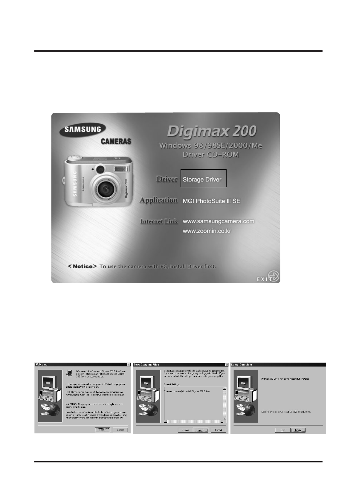
▶▶ HHooww ttoo sseett uupp tthhee ssooffttwwaarree ..
When you put the Driver CD-ROM provided withe this camera into the CD-ROM driver, the following
frame is automatically run.
. Camera Driver : This is the driver for connecting the PC to the Cmaera.
. MGI PhotoSuite III SE : Photography program.
※ If the frame is not displayed, run[Windows Explorer] and select [D:\CAMERA.EXE] in the CD-ROM
root directory.
1. Click the Storage Drive icon in the auotrun frame(above picture).
2. Start installation of Digimax 200 window will be displayed. Click[NEXT] to start installation.
Page 4
4
Ⅱ. FAQs
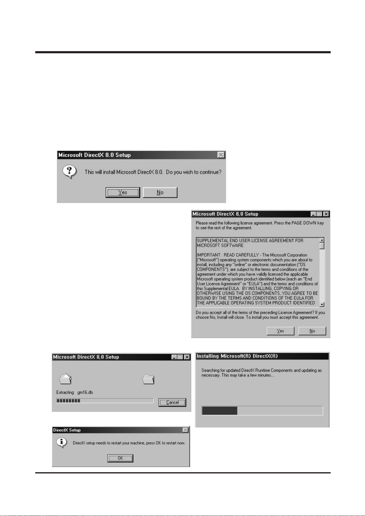
After the installatiion of Storage Driver has been finished, the following message appears.
※ DiretX 8.0 is needed to play moving pictures, and it should be installed to OS except WIN ME or
later versions.
(If the version of Windows Media Player is under 7.0, it’s mandatory to install Directx 8.0)
1. Start installation of Directx 8.0 will be displayed. Click[YES] to start installation..
2. An installation Complete window will be displayed.
Click[YES] and the installation will be completed.
Page 5
5
Ⅱ. FAQs
▶▶ HHooww ccaann II cchheecckk iiff tthhee UUSSBB SSttrrooggee ddrriivveerr hhaass bbeeeenn iinnsstt aalllleedd
ssuucccceessssffuullllyy??
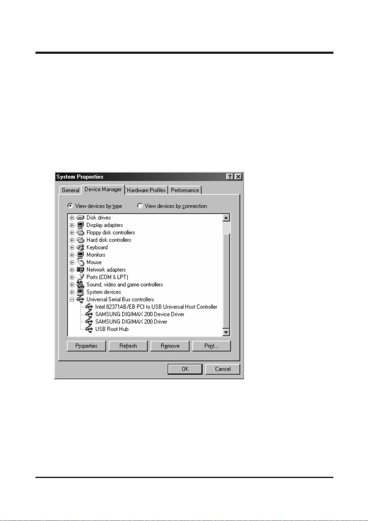
COnnect camera to the PC with the provided USB cable and turn it on at the PC mode.
This time, if verified normally, 「Samsung Digimax 200 Device Driver」and 「Samsung Digimax 200
Driver」will be displayed in the system properties as shown in the following figure.
To check System properties, double click 「Start → Setting → Controller → System → Device
Manager → Universal Serial Bus controller」or place the mouse cursor on 「My Computer」icon of PC
screen, press the right button of mouse, and select 「properties」from the menu and the
「Samsung Digimax 200 Device Driver」and 「Samsung Digimax 200 Driver」will be dispalyed in
the system properties as shown in the following figure.
To check Windows explprer, the [Removable Disk] will be displayed.
Page 6

6
Ⅱ. FAQs
▶▶ AApppplliiccaattiioonn
☞ NOTE 1.
When downloading data from PC to camera, the red LED blinks.
Although it appears on the PC monitor that the downloading has been completed, please remove the
USB cable or turn off the camera after the red LED of the camera is completely turned off.
If the camera is turned off or the USB cable is removed while the red LED is blinking, the computer
will stop operating.
☞ NOTE 2.
PLease use your caution if you want to download data using Card Reader.
Due to the differences depending on the Card Readers, image or Smart Media Card can be damaged
when using Card Reader to download.
Be sure to download data from the PC if the data is really important.
Q1. How to download the images from camera to the PhotoSuit.
A.1. When you use the Digimax 200, only [Computer] and [Album] from the list of options displayed
are available. You will be able to obtain images from the camera.
If you select the Digital camera (DIRECT) or (TWAIN), you can’t find the Digimax 200 camera.
Q2. Isn't the Driver for Macintosh use provided?
A3. The Driver for Macintosh use is not offered additionally but if it's Mac OS 9.X or better,
thus you can use it.
Connect camera and Mac with the USB cable and turn on at the PC mode. Then it will be
automatically recognized as a mobile disk.
There will be no problem for Mac OS 9.X or better, but not for the Mac OS X.
Q3. When installing USB Storage Driver, QuickTime 4.0 or better is shown in the system requirements.
QuickTime is not included in the Driver CD. How can I install USB Storage Driver?
A3. QuickTime 4.0 or better has more on the image comparing to the preceding version.
If you take advantage of this, the camera image can be shown more effectively.
Therefore be sure to install it.
If you go to http://www.apple.com/quicktime, you can download the up-to-date version.
Q4. How can I check the USB version in iMac?
A4. Click in the order of "Apple System Profiler - Device and volume" and the USB version is shown.
If the USB version is 1.0.1, updating is needed. But if it 1.1 or later, you can use it without updating.
http://developer.apple.com/hardware/usb/, you can download the Mac OS USB DDK 1.5.5.
Page 7
7
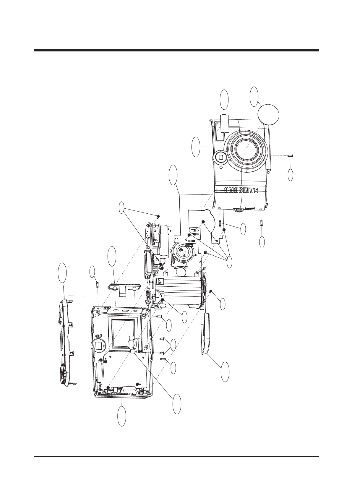
11.. BBOODDYY AA SS SS EEMMBBLLYY
ⅢⅢ.. EEXXPPLLOODDEEDD VVIIEEWWSS AANNDD PPAARRTTSS LLIISSTT
1-1
1-7
1-14
1-8
1-4
1-3
1-13
1-10
1-6
1-10
1-9
1-7
1-2
1-8
1-10
1-7
1-11
1-7
1-12
1-5
Page 8
8
ⅢⅢ.. EEXXPP LL OO DD EE DD VVII EE WWSS AA NNDD PPAA RRTTSS LL IISS TT
▶▶
PARTS LIST
1-1 9007-1682-01A Top Cover Ass’y 1
9007-1725-01A Top Cover Ass’y (NEXCA SDC-210) 1
1-2 9007-1684-01A Back Cover Ass’y 1
9007-1726-01A Back Cover Ass’y (NEXCA SDC-210) 1
1-3 9007-1683-01A Front Cover Ass’y (KENOX DIGIMAX 200) 1
9007-1727-01A Front Cover Ass’y (DIGIMAX 200) 1
9007-1728-01A Front Cover Ass’y (NEXCA SDC-210) 1
1-4 9001-0842-01A Power Board Ass’y 1
1-5 7204-0057-01A Tripod Holder 1
1-6 7212-1583-01A Lens Glass Cover 1
1-7 6003-0319-01A Screw 4
1-8 6003-0318-01A Screw 3
1-9 6003-0320-01A Screw 1
1-10 6003-0314-01A Screw 6
1-11 6003-0316-01A Screw 2
1-12 7217-2416-01A Battery Cover 1
1-13 7217-2425-01A Flash PMM A 1
1-14 7217-2418-01A USB Cover 1
Fig.No. Parts No. Parts Name Q'ty Remarks
Page 9
9
ⅢⅢ.. EEXXPP LL OO DD EE DD VVII EE WWSS AA NNDD PPAA RRTTSS LL IISS TT
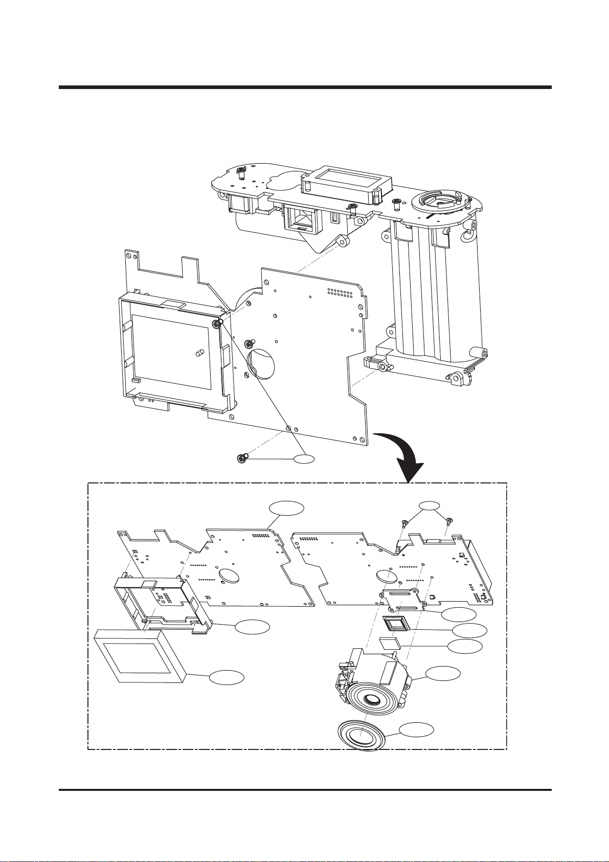
22.. MMAA IINN BB OOAA RR DD AASSSSEEMMBBLL YY
2-8
2-7
2-1
2-2
2-9
2-6
2-5
2-4
2-3
2-10
Page 10
10
ⅢⅢ.. EEXXPP LL OO DD EE DD VVII EE WWSS AA NNDD PPAA RRTTSS LL IISS TT
▶▶
PARTS LIST
2-1 9008-0467-01A Main Board SUB Ass’y1
2-2 6003-0314-01A Screw 2
2-3 9002-1021-01A Lens Ass’y1
2-4 2904-0007-01A OLPF 1
2-5 7309-0352-01A Rubber Cushion 1
2-6 7204-0058-01A CCD Plate 1
2-7 7216-0029-01A TFT LCD Holder 1
2-8 0704-0073-01A TFT LCD Ass’y1
2-9 6003-0317-01A Screw 1
2-10 7212-1584-01A Lens Circle Cover 1
Fig.No. Parts No. Parts Name Q'ty Remarks
Page 11

11
ⅢⅢ.. EEXXPP LL OO DD EE DD VVII EE WWSS AA NNDD PPAA RRTTSS LL IISS TT
33.. LLCC DD BBOOAARR DD && BBAA TTTT EERRYY BB OOXX AASS SSEE MMBBLL YY
3-13
3-9
3-10
3-14
3-2
3-5
3-4
3-7
3-6
3-11
3-19
3-3
3-12
3-8
3-15
3-16
3-1
Page 12

12
ⅢⅢ.. EEXXPP LL OO DD EE DD VVII EE WWSS AA NNDD PPAA RRTTSS LL IISS TT
▶▶
PARTS LIST
3-1 7217-2415-01A Battery Box 1
3-2 9007-1685-01A Battery Box Ass’y1
3-3 9003-0172-01A View Finder Ass’y1
3-4 6003-0313-01A Screw 2
3-5 6003-0314-01A Screw 4
3-6 7309-0351-01A Status LCD Rubber 1
3-7 0704-0072-01A LCD Panel 1
3-8 7409-1185-01A Battery Sheet UP 2
3-9 70 11-0397-01A Function Contact Ring 1
3-10 6107-0480-01A Mode Contact Spring 1
3-11 7409-1186-01A Status LCD Buffer 1
3-12 2401-0071-01A Main Condenser 1
3-13 72 11-0623-01A LCD Holder 1
3-14 9008-0471-01A LCD BoardAss'y 1
3-15 70 11-0398-01A Battery Connect 1
3-16 74 11-0843-01A Battery Connect Shaft 1
Fig.No. Parts No. Parts Name Q'ty Remarks
Page 13

13
ⅢⅢ.. EEXXPP LL OO DD EE DD VVII EE WWSS AA NNDD PPAA RRTTSS LL IISS TT
44.. FFRR OO NNTT CCOOVVEERR AA SSSSEEMMBBLL YY
▶▶
PARTS LIST
Fig.No. Parts No. Parts Name Q'ty Remarks
4-1 9007-1683-01A Front Cover Ass’y (KENOX DIGIMAX 200) 1
9007-1727-01A Front Cover Ass’y (DIGIMAX 200) 1
9007-1728-01A Front Cover Ass’y (NEXCA SDC-210) 1
4-2 6107-0477-01A SM Door Spring 1
4-3 7217-2417-01A VF Front Glass 1
4-4 7212-1585-01A Lens Plate 1
4-5 72 11-0624-01A Front LED Guide 1
4-6 7217-2419-01A SM Door Open Knob 1
4-7 7217-2455-01A Front Grip (NEXCA SDC-210) 1
4-8 Logo Plate (NEXCA SDC-210) 1
4-1
4-5
4-6
4-2
4-3
4-4
Page 14

14
ⅢⅢ.. EEXXPP LL OO DD EE DD VVII EE WWSS AA NNDD PPAA RRTTSS LL IISS TT
55.. TTOOPP CC OOVVEE RR AASSSSEEMM BB LL YY
▶▶
PARTS LIST
Fig.No. Parts No. Parts Name Q'ty Remarks
5-1 9007-1682-01A Top Cover Ass’y1
9007-1725-01A Top Cover Ass’y (NEXCA SDC-210) 1
5-2 7217-2426-01A Status LCD Window 1
5-3 7217-2421-01A Release Button 1
5-4 7204-0056-01A Rotate Tray 1
5-5 7217-2423-01A Flash Shutter 1
5-6 6107-0478-01A Shutter Spring 1
5-7 7017-0234-01A Twin Click SLR 1
5-8 6003-0321-01A Screw 2
5-9 6003-0313-01A Screw 1
5-3
5-1
5-6
5-4
5-7
5-5
5-2
5-9
5-8
Page 15

15
ⅢⅢ.. EEXXPP LL OO DD EE DD VVII EE WWSS AA NNDD PPAA RRTTSS LL IISS TT
66.. BBAACCKK CCOO VV EERR AA SS SS EEMMBBLLYY
6-5
6-2
6-4
6-6
6-7
6-8
6-1
6-3
6-9
6-17
6-14
6-10
6-16
6-15
6-13
6-12
6-11
Page 16

16
ⅢⅢ.. EEXXPP LL OO DD EE DD VVII EE WWSS AA NNDD PPAA RRTTSS LL IISS TT
▶▶
PARTS LIST
Fig.No. Parts No. Parts Name Q'ty Remarks
6-1 9007-1684-01A Back Cover Ass’y1
9007-1726-01A Back Cover Ass’y (NEXCA SDC-210) 1
6-2 6724-0006-01A Back Finder Glass 1
6-3 7217-2424-01A Circle Button 1
6-4 0709-0001-01A TFT LCD PMMA 1
6-5 72 11-0622-01A SM Card Door 1
7217-2456-01A SM Card Door (NEXCA SDC-210) 1
6-6 74 11-0842-01A SM Door Shaft 1
6-7 72 11-0627-01A Power Key Guide Plate 1
6-8 7217-2420-01A Power Key 1
6-9 72 11-0625-01A Back LED Guide 1
6-10 9008-0466-01A Key Board Ass'y 1
6-11 6107-0476-01A Circle Button Spring 1
6-12 72 11-0626-01A Contact Base 1
6-13 7217-2422-01A Mode Shutter 1
6-14 6003-0315-01A Screw 5
6-15 6003-0314-01A Screw 1
6-16 6107-0479-01A SM Door Open Spring 1
6-17 7409-1187-01A TFT LCD Buffer 1
Page 17

17
ⅢⅢ.. EEXXPP LL OO DD EE DD VVII EE WWSS AA NNDD PPAA RRTTSS LL IISS TT
77.. FFII NNDDEERR AA SSSS EEMM BBLLYY
7-2
7-5
7-4
7-1
7-10
7-6
7-7
7-8
7-9
7-13
7-3
7-11
7-12
Page 18

18
ⅢⅢ.. EEXXPP LL OO DD EE DD VVII EE WWSS AA NNDD PPAA RRTTSS LL IISS TT
▶▶
PARTS LIST
Fig.No. Parts No. Parts Name Q'ty Remarks
7-1 9003-0172-01A View Finder Ass’y1
7-2 7213-0314-01A Finder Cover 1
7-3 7213-0315-01A Finder Holder 1
7-4 6701-0053-01A Lens 5 1
7-5 6701-0052-01A Lens 4 1
7-6 7213-0316-01A Minor 1
7-7 6701-0051-01A Lens 3 1
7-8 6701-0050-01A Lens 2 1
7-9 6701-0049-01A Lens 1 1
7-10 7013-0139-01A Conduction 1
7-11 7309-0353-01A Flash Rubber 1
7-12 061 1-0027-01A X E T ube 1
7-13 7014-0039-01A Reflector 1
Page 19

19
ⅢⅢ.. EEXXPP LL OO DD EE DD VVII EE WWSS AA NNDD PPAA RRTTSS LL IISS TT
88.. PP AACCKKIINNGG IITTEEMM
8-1
SAMSUNG CAMERA
User Manual
Digital Camera
Digimax 130
8-2
8-3
6-4
8-5
8-6
8-7
3V(8MB
Page 20

20
ⅢⅢ.. EEXXPP LL OO DD EE DD VVII EE WWSS AA NNDD PPAA RRTTSS LL IISS TT
▶▶
PARTS LIST
Fig.No. Parts No. Parts Name Q'ty Remarks
8-1 6806-1173-01A User Manual (Korea) 1
6806-1174-01A User Manual (English) 1
6806-1175-01A User Manual (ENG/FRA/GER/SPA/NED/ITA) 1
6806-1176-01A User Manual (E/G/F/S/I/C_T) 1
6806-1186-01A User Manual (GER) 1
6806-1187-01A User Manual (FRA) 1
6806-1188-01A User Manual (ITA) 1
6806-1190-01A User Manual (SWE) 1
6806-1194-01A User Manual (ENG/SWE/POR/DEN/FIN) 1
6806-1195-01A Us er Manual (SPA) 1
6806-1196-01A User Manual (DUT)1 1
6806-1197-01A User Manual (POR) 1
6806-1198-01A User Manual (DEN) 1
6806-1199-01A User Manual (FIN) 1
6806-1200-01A User Manual (RUS) 1
6806-1202-01A User Manual (NEXCA DSC-210 KOR) 1
6806-1220-01A User Manual (ENG/GER) 1
8-2 4609-0024-01A CD-ROM (Driver & Application) 1
8-3 3802-0014-01A USB Cable 1
8-4 3802-0015-01A Video Cable 1
8-5 7409-1195-01A Strap 1
8-6 6904-0212-01A Pouch 1
8-7 4602-0001-01A SmartMedia Card (8M) 1
Page 21

21
Ⅳ. TROUBLESHOOTING
■■ IINNSSPPEECCTTIIOONN OOFF CCAAMMEERRAA
YY oouu ccaa nn tteesstt ee vv eerryy ffuunn cc ttiioonn aa nndd ooppeerraa ttiioonn ss ttaattee ooff cc aamm eerraa wwhheenn ssee lleecctt iinn gg tthhiiss
mmeenn yy ..
TTEE SSTT MMOO DDEE
a. Set the mode dial to PC mode.
b. After pressing the UP button and power on at the same time.
c. Test menu will displayed on TFT LCD as below.
11.. IINNSSPPEECCTTIIOONN OOFF CCAAMMEERRAA FFUUNNCCTTIIOONN..
1) Operating sequence :
Lens Check (Auto Focus 1 Cycle & Shutter operating 8 times) → Single Capture → Play → Delete
→ Motion Capture(20sec) → Play → Delete → Flash Check → Smart media card Check
2) Inspection
a. Select the BURN IN mode by pressing the UP(▲) / DOWN(▼) Key.
b. Press the enter button after selected the BURN IN mode.
c. It will be inspect every function of a camera as above sequence.
If it will be displayed the error message on the
TFT LCD,
. Auto Focus defect : AF error
. Shutter operating defect : MS error.
TEST MENUTEST MENUTEST MENU
LCD / KEY / LED / BUZ
SDRAM / SMC / P-CODE
TFT / TV
STROBE
AF / MS
FOCUS
COLOR TEST
BURN IN
TEST MENU
TEST MENU
TEST MENU
TEST MENU
TEST MENUTEST MENUTEST MENU
LCD / KEY / LED / BUZ
SDRAM / SMC / P-CODE
TFT / TV
STROBE
AF / MS
FOCUS
COLOR TEST
BURN IN
TEST MENUTEST MENUTEST MENU
LCD / KEY / LED / BUZ
SDRAM / SMC / P-CODE
TFT / TV
STROBE
AF / MS
FOCUS
COLOR TEST
BURN IN
UP(▲)
DOWN(▼)
RIGHT(▶)
LEFT(◀)
Enter
LCD
Power
Page 22

22
22.. OOTTHHEERRSS IINNSSPPEECCTTIIOONN
11)) LL CCDD // KKEEYY // LLEE DD // BB UUZZ
You can check below function when pushing enter button,
after selectiong this menu using UP(▲) / DOWN(▼) Key.
. LCD : TN LCD indication state.
. KEY : Operation state of each key.
. LED : LED on/off state.
. BUZ : Buzzer sound state.
When coming out of mode, you can return to TEST MENU
operating power off button.
22)) SSDDRR AAMM // SS MMCC // PP--CC OODDEE
You can check below function when pushing enter button,
after selectiong this menu using UP(▲) / DOWN(▼) Key.
. SDRAM : SDRAM check.
. SMC : Smart media card check.
. P-CODE : Using P-CODE when upgrading Firmware,
check to upgrade exactly.
. VERSION : Firmware version check.
※ When upgrading to 31-8, P-CODE should be 09601
indicating upgrade normally.
If P-CODE is different, you have to upgrade again.
33)) TTFF TT // TTVV
You can check below function when pushing enter button,
after selectiong this menu using UP(▲) / DOWN(▼) Key.
. TFT : Push UP(▲) button once more, preview screen
comes out and indicate on LCD.
. TV : If you press LCD button, you can check NTSC/PAL
transformation.
If you press enter button once more, return to TEST MENU.
TEST MENU
TEST MENUTEST MENUTEST MENU
LCD / KEY / LED / BUZ
SDRAM / SMC / P-CODE
TFT / TV
STROBE
AF / MS
FOCUS
COLOR TEST
BURN IN
TEST MENU
TEST MENU
TEST MENU
TEST MENU
TEST MENU
TEST MENU
TEST MENUTEST MENUTEST MENU
LCD / KEY / LED / BUZ
SDRAM / SMC / P-CODE
TFT / TV
STROBE
AF / MS
FOCUS
COLOR TEST
BURN IN
TEST MENU
TEST MENU
TEST MENU
TEST MENU
TEST MENU
TEST MENU
TEST MENU
TEST MENU
TEST MENUTEST MENUTEST MENU
LCD / KEY / LED / BUZ
SDRAM / SMC / P-CODE
TFT / TV
STROBE
AF / MS
FOCUS
COLOR TEST
BURN IN
TEST MENU
TEST MENU
TEST MENU
TEST MENU
TEST MENU
TEST MENU
Ⅳ.
TT RR OO UU BB LL EE SS HH OO OO TT IINNGG
Page 23

23
44)) SSTTRROOBB EE
You can check Flashing state when pushing enter button,
after selectiong this menu using UP(▲) / DOWN(▼) Key.
(Flash firing three times)
55)) AAFF // MMSS
You can check operation state of Shutter and Lens when
pushing enter button, after selectiong this menu using
UP(▲) / DOWN(▼) Key.
TEST MENU
TEST MENUTEST MENUTEST MENU
LCD / KEY / LED / BUZ
SDRAM / SMC / P-CODE
TFT / TV
STROBE
AF / MS
FOCUS
COLOR TEST
BURN IN
TEST MENU
TEST MENU
TEST MENU
TEST MENU
TEST MENUTEST MENUTEST MENU
LCD / KEY / LED / BUZ
SDRAM / SMC / P-CODE
TFT / TV
STROBE
AF / MS
FOCUS
COLOR TEST
BURN IN
TEST MENU
TEST MENU
TEST MENU
Ⅳ
.. TTRR OO UUBBLL EESS HH OO OO TT IINNGG
Page 24

24
33.. BBLLOOCCKK DDIIAAGGRRAAMM
U6 TI
TLV 990-21
U7 SONY
CDX2470R
U8 SONY
CCD
Smart Media
Key Board
U9, U10
Lens Control
U3 Flash Memory
29LV400TC-90
U11 SDRAM
KM432S203B
LCD. Strobo
USB Port
(USB jack)
TV Out
U2 TFT
LV4135
Power Supply
(Power Board)
U1 TI DSP
TMS320DSC21
Battery 3V Adaptor 3V3
SYS-5V
SYS-1.8V, 3.3V
CCD-15V,-7.5V,3.3V
TFT-12V,3.8V,3.3V
M/F-3.8V
CCD_D[0-11]
CCDIN
V1-V4
RG
H1,2
GIO[13-18]
GIO[25,
29-31]
USB
ATTACH
D+D-
A[0-21]
D[0-15]
SDR_A
[14-0]
SDR_D
[31-0]
RGB VSYNC
HSYNC
COMP
OSITE
Ⅳ.
TT RR OO UU BB LL EE SS HH OO OO TT IINNGG
Page 25

25
44.. PPAARRTTSS AARRRRAANNGGMMEENNTT FFOORR EEAACCHH PPCCBB
1) Main PCB Ass'y (TOP)
▶ Doesn't Power ON.
. Component N.G (Q8,,J6,U3)
. Connect N.G (JP2)
▶ Power off automatically.
. Component N.G (S1,J6)
▶ LENS Operating Defect.
. Connect N.G (CON1)
▶ Shutter Operating Defect.
. Connect N.G (CON1)
▶ TV OUT Defect.
. Component N.G (C138,C70)
. Connect N.G (J8)
▶ TFT LCD Defect.
. Image BLACK (U7,U8,T10,L3,C70,C119,JP2,JP4)
. Image Defect (U7,U8,U17,T10,C119,R141,JP2JP4)
. Image Noise (U6,C70,VR2)
▶ Download Defect.
. Component N.G(Y3)
. Connect N.G (JP1)
Ⅳ
.. TTRR OO UUBBLL EESS HH OO OO TT IINNGG
C67
R70
L5
R102
CCD Parts
R69
C66
R2
Q12
R108
C71
U13
C129
C59
Q13
D6
D7
R71
R74
R76
TV OUT
J8
JP1
J6
C104
C74
R73
R75
C138 C106
U7
R106
U12
C72
R81
C34 R85
C32 R86
C33 R80
R107
C23
C41
C43
U8
R136
R30
C31
CCD
Q16
C33
C32
C29
R47
C34
R38
R41
C46
C139
L3
Q17
C124
R144
R28
C119
R125
Q14
R1
J2
CON1
+
C114
-
R46
C47
C48
R5
C44
R29
R31
R146
JP4
TFT LCD ControllerTV Invertor
C123
C68
U16
C64
C70 C69
C57
dsp Parts
S1
C65
C62
C61
R99C102Q18
16
R3
C14
C22
JP2
R121
R7
R14
C3
R6
C130
C131
C13
C27
R22C9C28
R83
R82
R23
C1
U1
C5
R8
R25
C2
C6
C4
R59
C120
C8
R143 C95
Q9
C16
J9 J12
C58
U3
Flash Memory
Page 26

26
▶ Doesn't Power ON.
. Component N.G
(Y1,Y2,R99,U11,L1,U2,U17)
. Connect N.G
(JP3, J3)
▶ Power off automatically.
. Connect N.G (JP3)
▶ Flash Fire Defect.
. Connect N.G (J3)
▶ LENS Operating Defect.m
. Component N.G (Q7,U10)
▶ Shutter Operating Defect.
. Component N.G (U9)
TV OUT Defect
. Component N.G (C70)
▶ TFT LCD Defect
. Image BLACK (U6,U8,T10,L3)
. Image Defect (U2,U6,U17,T10,C119,R141)
. Image Compression Defect (Y1,Y2,R121)
. Image Noise (U6)
Ⅳ.
TT RR OO UU BB LL EE SS HH OO OO TT IINNGG
2) Main PCB Ass'y (BOT)
J3
SDRAM
R116
DSP
Power
48MHz
L1
D8
D4
C101
D3
C100
C99
JP3
CCD Parts
ADC
D5
U11
SAMSUNG 127
1
Power
27MHz
R68
R67
C60
U15
B1
K4S63232E-TC60
C128
R88
C88
R149
Y5
R155
R109
C80
U6
R90
R120
R4
R66
R20
Q4
R24
R27
Y1
R152
R154
C15
R84
R151
R150
C105
R61
R63
R26
R148
R48
R16
R19
C84
C134
C135
C133
C132
C110
R50
R54
C7
C24
C25
D9
R18
R55
C26
R17
C122
D2
R87
C86
R89
C89
C92
R91
Q6
C50
C56
C121
R60
R21
R15
J3
C42
C23
C53
R17
C93
Y2
R64
C116
R44
C118
U9
Q7
C115
C127
R96
C117
U2
L2
R147
C19
C45
C125
C126
R9
U10
C140
R145
R65
R62
R131
R132
R133
C54
R134 R135
Q15
R92
R93
C49
C30
R49
Lens Control 1 Lens Control 2
TFT LCD Controller
R115
RTC
Y4
R112
R58
C137
TV OUT
C136
USB
C109
R156
Page 27

27
▶ Doesn't Power ON.
. Component N.G (U1,U2,U3,D8,L7)
▶ TFT LCD Defect.
. Image Defect (U1)
. Image Noise (C20,C21)
▶ Electric Leakage.
. Component N.G (U2,C15)
Ⅳ
.. TTRR OO UUBBLL EESS HH OO OO TT IINNGG
3) Power PCB Ass'y (TOP)
D2
R35
R30
L7
Power(sys)
+1.8V
U3
C36
Power(sys)
+3.3V
C21
C37
C38
R25
C29
C18
R26
C20
R24
U2
C35
C15
R31
L2
C1
R22
C10
C14
R19
R20
13
R21
L1
R17
C13
12
Q1
R11
C8
R12
R8
U1
R1
C3
Q2
C2
R15
C6
1
R4
C5
C4
R2
R6
R5
R3
L3
C23
Q6
C24
Q7 Q11
D5
R28
Q5
C25
R27
Q8
C27
L4
24
36
R29
37
36
C27
Q14
Page 28

28
▶ Doesn't Power ON.
. Component N.G (D8)
. Connect N.G (JP1,JP2)
▶ TFT LCD Defect.
. Image BLACK (JP2)
. Image Noise (JP1)
Ⅳ.
TT RR OO UU BB LL EE SS HH OO OO TT IINNGG
4) Power PCB Ass'y (BOT)
L5
R34
C28
R33
C34
R23
Q3
C33
Power +3.3V
R16
R18
R14
JP2
12
R7
C12
R9
R10
C19
C22
C7
D1
C11
R13
C16
J1
Power +15V
D3
D4
D6
T1
C32
Q9
C17
Q4
R32
Q13
D7
Q12
C31
C30
C26
L6
D8
JP1
1
11
2
Power -7.5V
Page 29

29
▶ Charge Defect.
. Connect N.G (CON1)
. Component N.G
(T1,D1,D3,U2,Q1,Q2)
Ⅳ
.. TTRR OO UUBBLL EESS HH OO OO TT IINNGG
5) LCD PCB Ass'y
Switch contact
Flash Parts
C1
SW1
C2
S3
2
1
Flash Parts
LCD1 1
R2
R3
S1
S2
R28
R30R29
C13
R18
C8
C5
D10
Q3
U2
R27
Swtich Parts
R17
Q1
R15
D4
R16
D3
J4
R19
J5
R14
J6
R24
D2
C9
R5
CONN1
R10
R9
R8
C6
D7
8
T1
1
L1
5
T2
D6
D8
R23
C11
R26
D14
4
C12
Q4
R22
R20
D5
R21
C10
Q2
U1
48
1
2
LCD Driver
C3
C1
R1
R12
R7
C4
R13
R11
C2
R6
R4
Page 30

30
▶ UPLOAD/DOWNLOAD Defect.
. Connect N.G (J1,JP1)
▶ Camera Malfunction.
. Connect N.G (SW1,JP1)
Ⅳ.
TT RR OO UU BB LL EE SS HH OO OO TT IINNGG
6) SM PCB Ass'y
R9
R8
C2
R6
S5
S1
S2
R3
26 JP1
2
1
26
25
R1
C1
R7
S6
D1
R10
R2
S4
R5
S3
R4
2
2728
SW1
25
J1
23
21
1
36
3
23
5
18
8
15
10
13
26
24
Page 31

31
Ⅴ
.. AADDJJUUSSTTMMEENNTT
11.. FFOOCCUUSS AADDJJUUSSTTMMEENNTT
In case of replacing MAIN PCB ass'y or LENS ASS'Y with new one, you have to adjust the FOCUS.
a. Set the camera at 2m distance as above figure.
b. Make a test mode and select the FOCUS menu by using the UP(▲) / DOWN(▼) Key.
c. press the Enter button and then it will be adjusts automatically.
TEST MENUTEST MENUTEST MENU
LCD / KEY / LED / BUZ
SDRAM / SMC / P-CODE
TFT / TV
STROBE
AF / MS
FOCUS
COLOR TEST
BURN IN
a(cm) = 58
b(cm) = 76
c(mm) = 10
d(mm) = 10
Illumination : a fluorescent light
a
CHART
CAMERA
b
2m
c
d
Page 32

32
Ⅴ
.. AA DD JJ UU SSTT MMEE NNTT
22.. TTFFTT LLCCDD CCoolloorr IInnssppeeccttiioonn aanndd aaddjjuussttmmeenntt
In case of replacing MAIN PCB ass'y or TFT LCD with new one, you have to adjust the Color.
[Fig-1] [Fig-2]
a. Make a test mode and select the COLOR TEST menu by using the UP(▲) / DOWN(▼) Key.(Fig-1)
b. TFT LCD will displayed as fig-2, after press the enter button.
c. Color check method is that you can check color on LCD state when selecting Mode dial as below
(Fig-3)
d. Color adjust method of TFT LCD
i. Number presents on LCD like below pressing enter button after first selecting COLOR TEST mode.
ii. Adjust menthod of each item is to adjust beyond adjust limit referring each item.
TEST MENU
TEST MENUTEST MENUTEST MENU
LCD / KEY / LED / BUZ
SDRAM / SMC / P-CODE
TFT / TV
STROBE
AF / MS
FOCUS
COLOR TEST
BURN IN
Green
Red
Blue
Gray Bar Chart
TESTTING
TESTTINGTESTTINGTESTTING
0008 132 128 120
ⓐ
ⓑ
ⓒⓓ
ⓐⓐ
You can adjust contrast of LCD keeping
press LCD button continuously adjust
limit : 0006~0010
ⓑⓑ
Adjust bright of LCD
value to 132 pressing
Flash/Macro button.
ⓒⓒ
Adjust to red color when
pressing up(▲) key of four
direction keys, adjust green
when pressing down(▼) key.
(Adjust limit : 100~140)
ⓓⓓ
Adjust to Yellow color when
pressing left(◀) key of four
direction keys, adjust blue
when pressing right(▶) key.
(Adjust limit : 100~140)
 Loading...