

Samsung DH60 T Series, DC60*TV Series, DH48*T Series, DC48*TV Series, DC60*T Series Installation Manual
...
INSTALLATION
HSILGNE
MANUA
DH60T Series
DH48T Series
DC60T Series
DC48T Series
DC60TV Series
DC48TV Series
L
LOÑAPSE
SI
AÇ
N
ARF
System Air Conditioner(Cooling and Heating)
This product is not manufactured for Iran.
SVC Warranty will not be applicable and the user will be responsible
for service expenses when the product is used in Iran.
E
S F A
DB98-23539A(7)
Safety Precautions
The following safety precautions must be taken when using your air conditioner.
◆ The unit should not be installed by the user. Ask the dealer or authorized
company to install the units except room air conditioners for the U.S.A and
Canada area.
◆ If the unit is installed improperly, water leakage, electric shock or fire may
result.
◆ Mount with the lowest moving parts at least 2.5 m above the floor or grade
level. (If applicable)
◆ The manufacturer does not assume responsibility for accidents or injury
caused by an incorrectly installed air conditioner. If you are unsure about
installation, contact an installation specialist.
◆ When installing the built-in type air conditioner, keep all electrical cables
such as the power cable and the connection cord in pipe, ducts, cable
channels e.t.c to protect them against liquids, outside impacts and so on.
◆ This appliance is not accessible to the general public. This appliance
should be installed according to the provided installation
instruction.
WARNING
INSTALLING THE UNIT
◆ If the power cord of this air conditioner is damaged, it must be replaced by
the manufacturer, its service agent or similarly qualified persons in order to
avoid a hazard.
◆ The unit must be plugged into an independent circuit if applicable or
connect the power cable to the auxiliary circuit breaker. An all pole
disconnection from the power supply must be incorporated in the fixed
wiring with a contact opening of >3mm.
◆ Do not use an extension cord with this product.
◆ If the unit is equipped with a power supply cord and a plug, the plug must
be accessible after installation.
◆ The air conditioner must be installed in accordance with national wiring
regulations and safety regulations wherever applicable.
POWER SUPPL Y LINE,
FUSE OR CIRCUIT
BREAKER
Risk of electric shock. • Can cause injury or death. • Disconnect all
remote electric power supplies before servicing, installing or cleaning.
• This must be done by the manufacturer or its service agent or a similar
qualified person in order to avoid a hazard.
E-2
E-3
H
SILGN
E
Preparation for Installation ............................................................................ 4
Deciding on Where to Install the Air Conditioner ........................................ 5
Indoor Unit Installation ................................................................................ 10
Purging the Unit .......................................................................................... 11
Connecting the Connection Cord ................................................................ 11
Connecting the Cables to the Outdoor Unit ................................................ 16
Drain Hose Installation ................................................................................ 17
Connecting the Indoor Unit Assembly Piping .............................................. 19
Cutting/Flaring the Pipes ............................................................................. 20
Checking Correct Grounding ....................................................................... 21
Fixing the Unit in Position ........................................................................... 22
Connecting Up and Removing Air In the Circuit ......................................... 23
Performing Leak Tests ................................................................................ 24
Insulation ..................................................................................................... 25
Adjusting Air Flow ........................................................................................ 26
Setting Up the Model Option ....................................................................... 27
Assigning Address to Indoor Unit ................................................................ 30
Additional Functions .................................................................................... 31
Drain Pump Installation (Optional) .............................................................. 33
Setting Up Option Switches (Outdoor unit) ................................................. 35
Testing Operations ...................................................................................... 37
Troubleshooting .......................................................................................... 38
Parts List ................................................................................................... 42
Contents
................................ 25
Pump Down Procedure (When removing the product)
E-4
Preparation for Installation
When deciding on the location of the air conditioner with the owner,
the following restrictions must be taken into account.
Do NOT install the air conditioner in a location where it will come into
contact with
the following elements:
◆
Combustible gases
◆
Saline air
◆
Machine oil
◆
Sulphide gas
◆
Special environmental conditions
If you must install the unit in such conditions, first consult your dealer
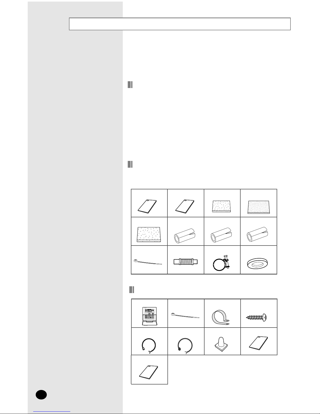
Cable-Tie Cable
Clamp M4 x 16 Tapped
Screws
Indoor unit power
drawing cable
Communication cable of
the wired remote
controller
Wire joint
Owner’s Instruction
Installation Manual
Wired remote controller
Owner’s
Instructions(1)
Installation
Manual(1)
Insulation Cover
Pipe
in
(1)
Insulation Cover
Pipe out(1)
Insulation Pipe in(1)
Insulation Cover
Drain(1)
Insulation Pipe out(1)
Clamp hose(2)
Cable-Tie(8)
Flexible hose(1)
Accessories
General
Wired Remote Controller Accessories
◆ The following accessories are supplied with the indoor unit.
The type and quantity may differ depending on the specifications.
Insulation Drain (1)
Rubber(8)
E-5
Deciding on Where to Install the Air Conditioner
Indoor Unit
There must be no obstacles near the air inlet and outlet.
Install the indoor unit on a ceiling that can support its weight.
Maintain sufficient clearance around the indoor unit.
Make sure that the water dripping from the drain hose runs away cor-
rectly and safely.
The indoor unit must be installed in this way, that they are out of public
access. (Not touchable by the users)
After connecting a chamber, insulate the connection part between the
indoor unit and the chamber with t10 or thicker insulation. Otherwise,
there can be air leak or dew from the connection part.
20mm or more
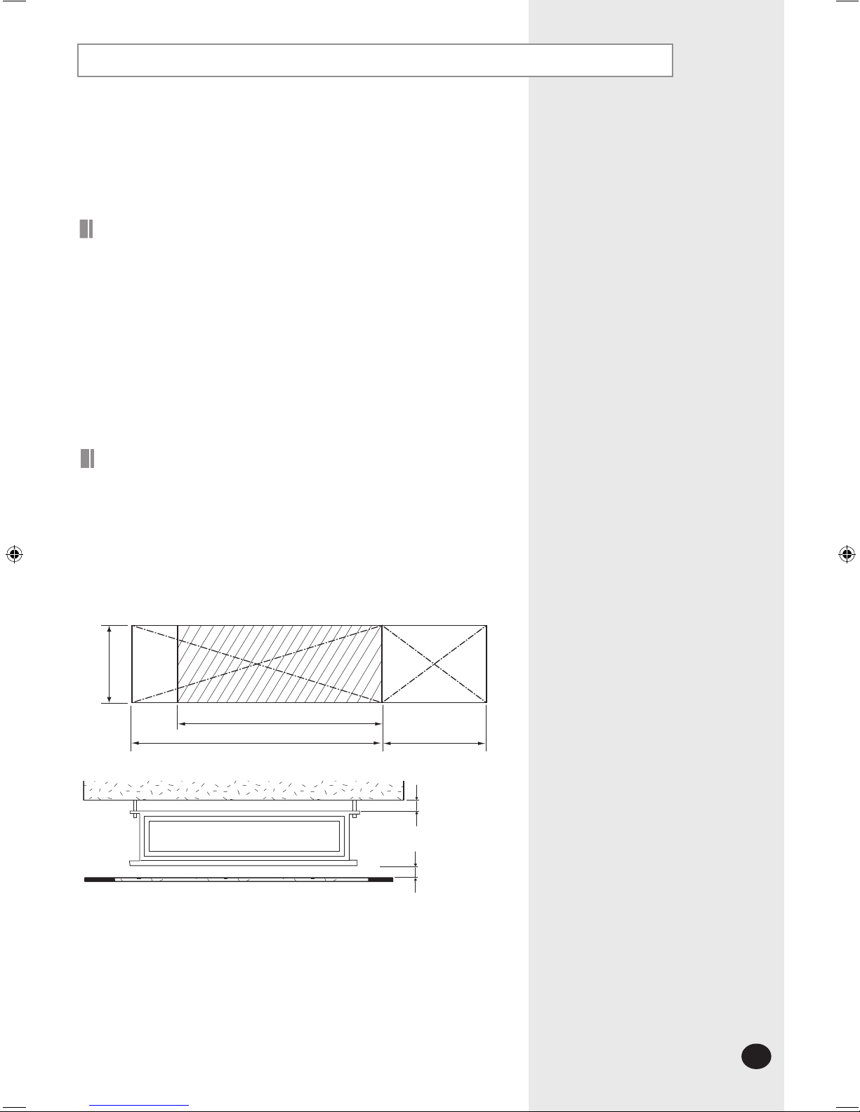
Space Requirements for Installation& Service
Construction Standard for Inspection Hole
1)
In case, the ceiling is tex tile, Inspection hole dose not need.
2)
In case, the ceiling is plaster board, Inspection hole depends on Inside
height of the ceiling.
a.
Height is more than 1m : Only "B" [Inspection for PBA] is applied.
b.
Height is less than 1m : Both "A"&"B" are applied.
c. "A"&"B" are inspection holes .
Unit Width(W)
"A"=W+100mm
Unit Depth(D)+50mm
"B"=500mm
20mm or more
You must have 20mm or more space between the ceiling and the bottom of
indoor unit. Otherwise, the noise from the vibration of indoor unit may bother
the user.When the ceiling is under construction, the hole for check-up must be
made to take service, clean and repair the unit.
It is possible to install the unit at an height of between 2.2~2.5m from the
ground, if the unit has a duct with a well defined lenght (300mm or more), to
avoid fan motor blower contact.
Deciding on where to install the Air Conditioner (Continued)
Outdoor Unit
◆ The outdoor unit must not be placed on its side or upside down, as the
compressor
lubrication oil will run into the cooling circuit and seriously
damage
the unit.
◆ Choose a location that is dry and sunny, but not exposed to direct sunlight or
strong
winds.
◆ Do not block any passageways or thoroughfares.
◆ Choose a location where the noise of the air conditioner when running and
the
discharged air do not disturb any neighbours.
◆ Choose a position that enables the pipes and cables to be easily connected
to
the indoor unit.
◆ Install the outdoor unit on a flat, stable surface that can support its weight
and
does not generate any unnecessary noise and vibration.
◆ Position the outdoor unit so that the air flow is directed towards the open
area
.
◆ Maintain sufficient clearance around the outdoor unit, especially from a radio,
compute
r, stereo system, etc.
◆ If the outdoor unit is installed at a height, ensure that its base is firmly fixed in
position
.
◆ Make sure that the water dripping from the drain hose runs away correctly
and
safely.
e
r
o
m
r
o
m
5
.
1
Indoor Unit
Circuit
Breaker
Outdoo
r
Unit
Remote
Controller
e
r
o
m
r
o
m
1
e
r
o
m
r
o
m
1
e
r
o
m
r
o
m
5
.
1
e
r
o
m
r
o
m
5
.
1
m
5
.
1
m
r
o
e
r
o
Circuit Breaker
Stere
o
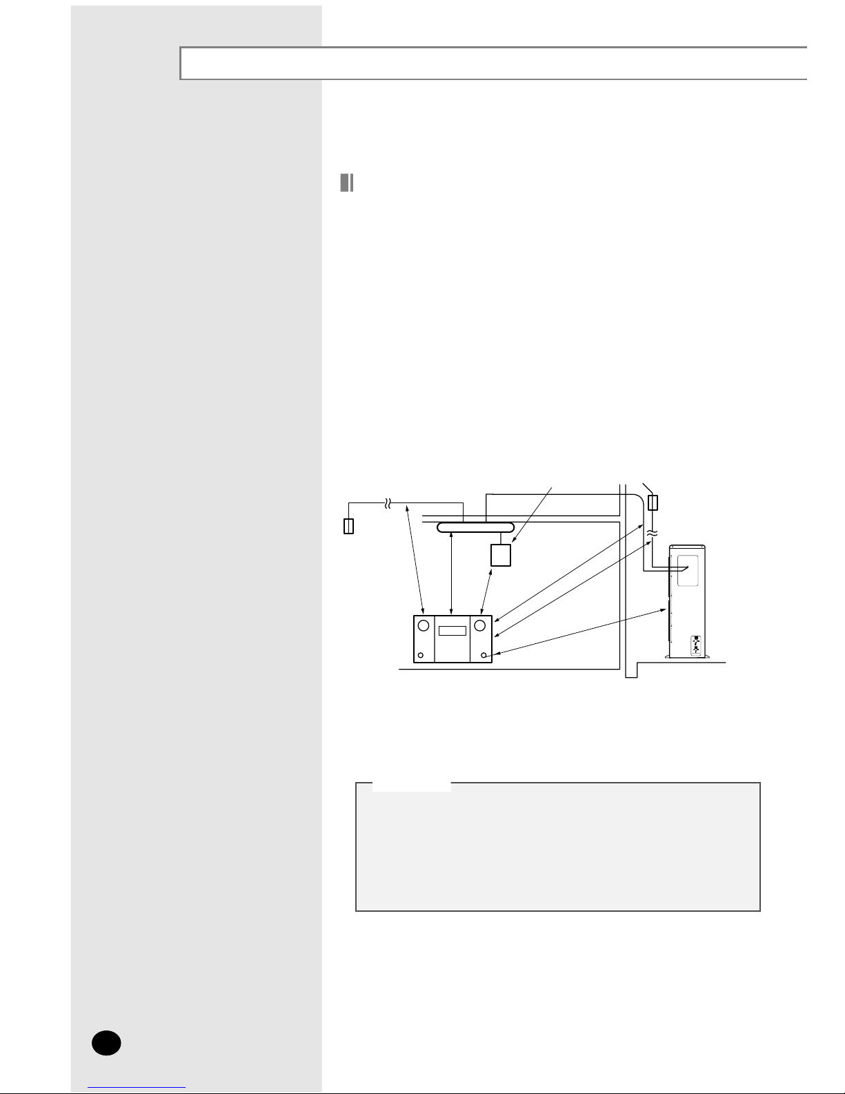
◆ You have just purchased a system air conditioner and it
has been installed by your installation specialist.
◆ This device must be installed according to the national
electrical rules.
CCCCAAAAUUUUTTTTIIIIOOOONN
NN
E-6
◆ When installing the model DC48FTVX/DC60GTVX/
DC60FTVX get rid of the cushion on the top of compressor.
ero
m
r
o
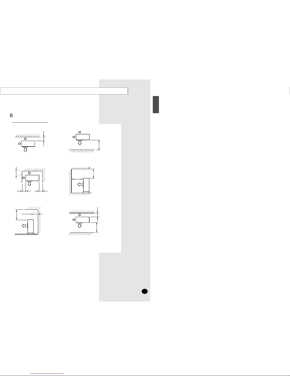
300
❋ When the air outlet is opposite the wall
erom
r
o
2000
❋ When the air outlet is towards the wall
e
rom
ro
300
300 or more
600
or more
❋ When 3 sides of the outdoor unit are
blocked
by the wall
erom
ro
0
051
2000 or more
❋ The upper part of the outdoor unit and
the
air outlet is towards the wall
e
rom
ro
005
300 or more
❋ The upper part of the outdoor unit
and
the air outlet is opposite the wall
e
r
o
m
ro
00
3
ero
m
r
o
2000
❋ When front and rear side of the outdoor
unit
is towards the wall
Unit : mm
Space Requirements for Outdoor Unit
When installing 1 outdoor unit
H
SILGN
E
E-7
E-8
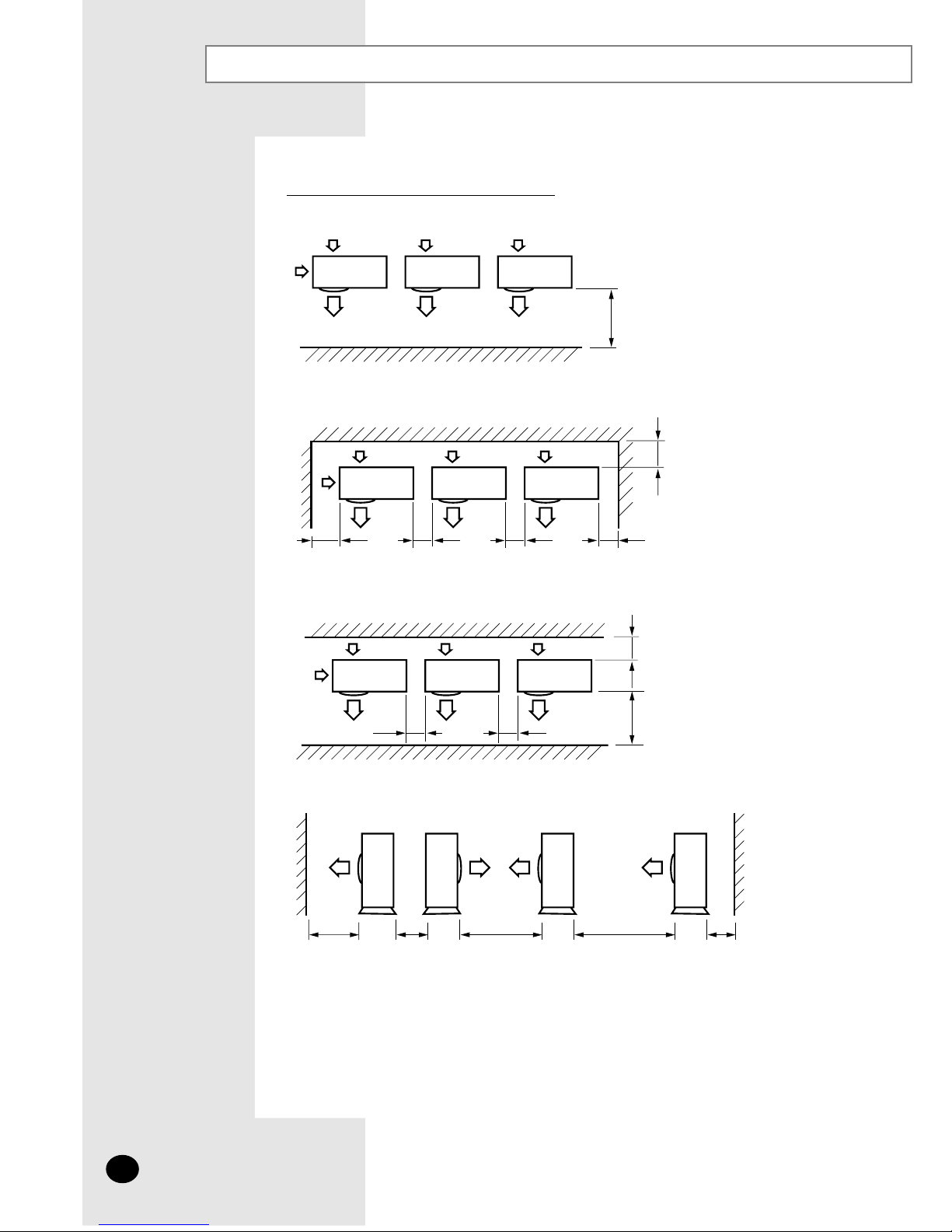
Deciding on where to install the Air Conditioner (Continued)
Unit : mm
e
rom r
o
0
0
02
✽
When the air outlet is towards the wall
erom
ro
003
300 or more
200
0
or more 1000 or more 5000 or more 200 or more4000 or more
60
0
or more 600 or more
e
ro
m
r
o
0
03
e
rom ro
000
2
600 or more 600 or more
60
0 or more
✽
When 3 sides of the outdoor unit are blocked by the wall
✽
When front and rear side of the outdoor unit is towards the wall
✽✽
When front and rear side of the outdoor unit is towards the wall
When installing more than 1 outdoor unit
ENGLISH
102
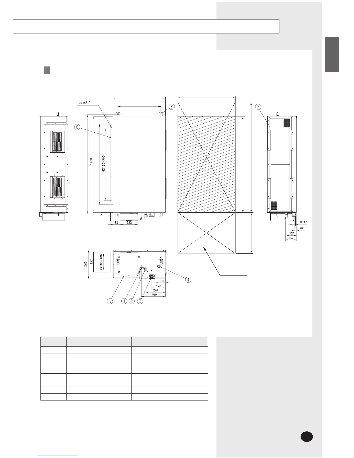
No. Name Description
1 Liquid pipe connection ø9.52
2 Gas pipe connection ø19.05
3 Drain pipe connection OD32 ID26
4 Drain pipe connection Using drain pump (Optional)
5 Power supply connection
6 Air discharge flange
7 Air filter
8 Hook M8~M10
Unit : mm
Drawing of the indoor unit
E-9
Indoor Unit Installation
E-10
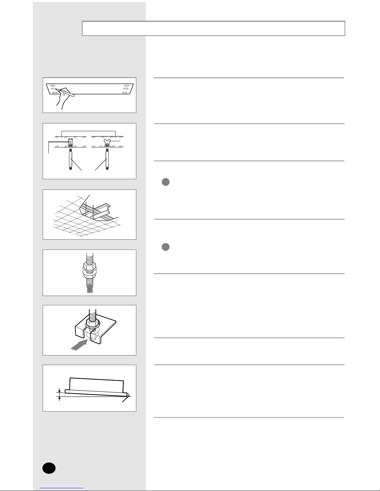
1
Mark the place to insert the suspension bolt where you want to install the
indoor unit.
2
Insert bolt anchors. Use existing ceiling supports or construct a suitable
support as shown in figure.
3
Install the suspension bolts depending on the ceiling type.
4
Screw eight nuts to the suspension bolts making space for hanging
the indoor unit.
5
Hang the indoor unit to the suspension bolts between two nuts.
6
Screw the nuts to suspend the unit.
7
Adjust level of the unit by using measurement plate for all 4 sides.
Ensure that the ceiling is strong enough to support
the weight of the indoor unit.
Before hanging the unit, test the strength of each
attached suspension bolt.
IMPORTANT
You must install the suspension bolts more than 4
when installing the indoor unit.
IMPORTANT
◆ Tubing must be laid and connected inside the ceiling when
suspending the unit. If the ceiling is already constructed,
lay the tubing into position for connection to the unit before
placing the unit inside the ceiling.
NNNNoooottttee
ee
◆ Refer to page 9 for the dimension.
NNNNoooottttee
ee
◆ For proper drainage of condensate, give a 10mm slant to the
left or right side of the unit which will be connected with the drain
hose, as shown in the figure. Make a tilt when you wish to install
the drain pump, too.
NNNNoooottttee
ee
Concrete
Suspension bolt(M8)-field supply
Hole in anchor
Hole in plug
Insert
Ceiling support
Drain hose connection port
10mm
ENGLISH
E-11
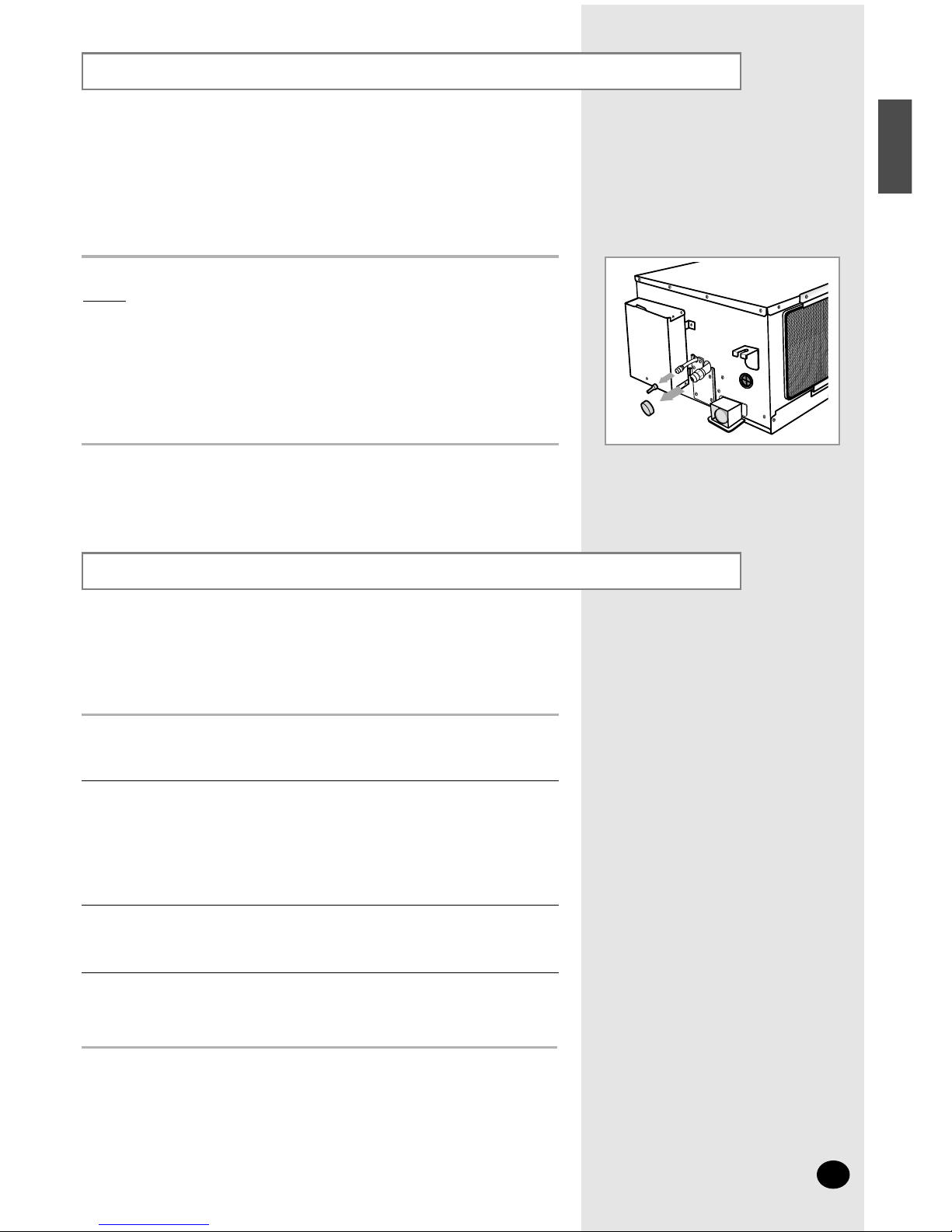
Purging the Unit
On delivery, the indoor unit is loaded with an inert nitrogen gas.
All this gas must therefore be purged before connecting the assembly
piping. To purge the inert gas, proceed as follows.
Unscrew the caps at the end of each pipe.
Result:
All inert gas escapes from the indoor unit.
◆ To prevent dirt or foreign objects from getting into the pipes
during installation, do NOT remove the caps completely until
you are ready to connect the piping.
NNNNoooottttee
ee
Connecting the Connection Cord
The indoor unit is powered from the outdoor unit via the connection cord.
◆ When connecting the cables, you must pass them through
the cable clamp to fix them securely.
NNNNoooottttee
ee
Remove the screw on the electrical component box and remove the cover
plate.
1
Route the connection cord through the side of the indoor unit and connect
the cable to terminals as shown in pages 12 and 15.
2
Route the other end of the cable to the outdoor unit through the ceiling &
the hole on the wall.
3
Reassemble the electrical component box cover, carefully tightening the
screw.
4
E-12
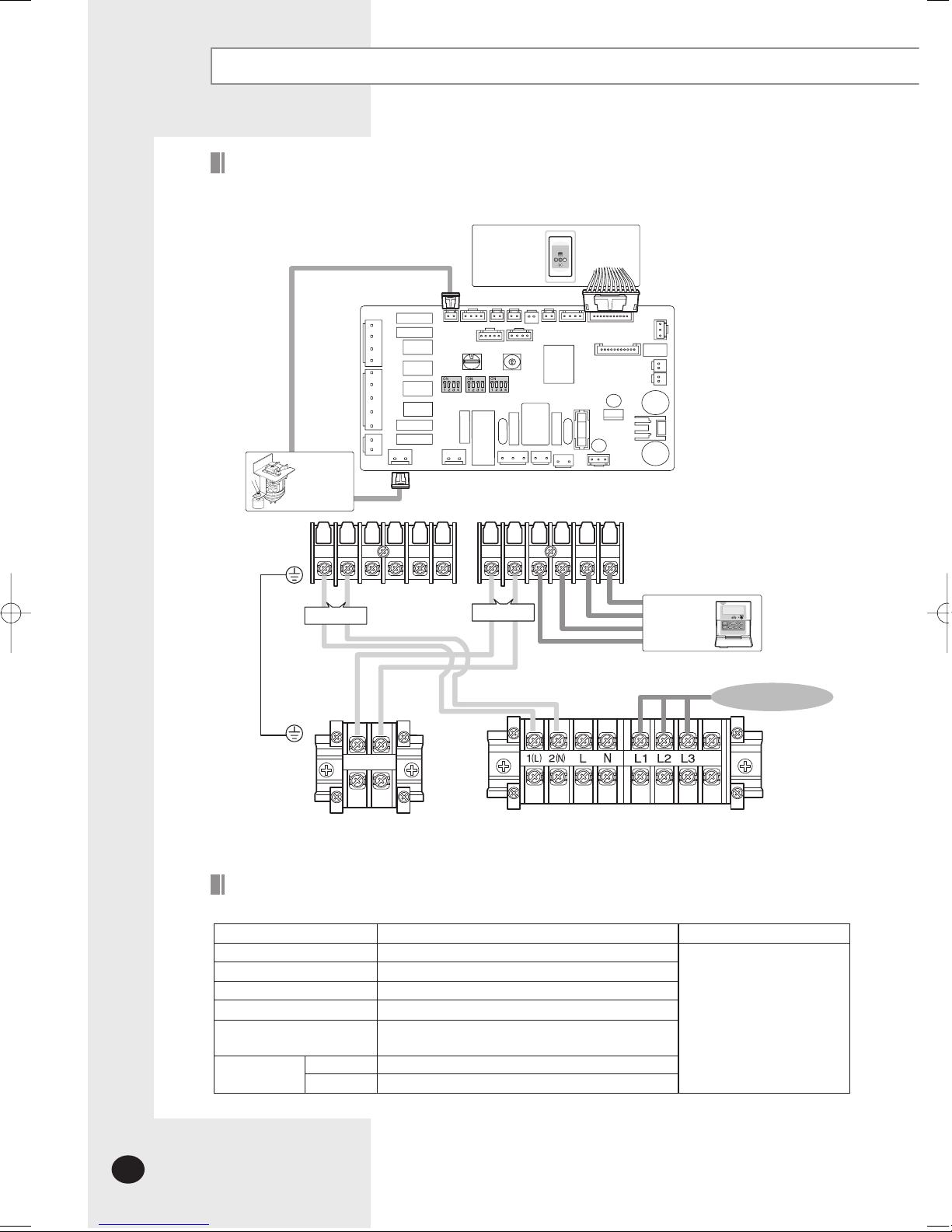
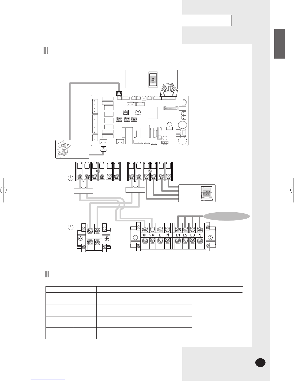
Connecting the Connection Cord (Continued)
1(L)
2(N)
Vc Vc Vw Vw F1 F2 V1 V2 F3 F4
F1 F2
Receiver &
Display Unit
(Optional)
Float Switch
Drain Pump
(Optional)
Wired
Remote
Controller
MAIN PCB
3ø220V~, 60H
z
Communication
Power
The following electrical characteristics must be respected.
MODEL
Power
Circuit breaker
Indoor unit power cable
Communication cable
Wired remote controller power
& communication cable
Power cable
20m or less
50m or less
DH48FTA(X), DH60FTA(X), DC48FTA(X), DC60FTA(X)
3ø 220V~, 60Hz
30A
1.25mm
2
(CV, 3 wire)
0.75~1.0mm2(CV, 2 wire)
The power cables are not
supplied with the air
conditioner.
The user should purchase
them separately.
0.5~0.75mm
2
(CV, 2 wire)
5.5mm
2
(CV, 4 wire)
8.0mm2(CV, 4 wire)
Note
MAIN POWER
Indoor Unit
Outdoor Unit
Wiring Diagram (DH48FTA, DH60FTA, DC48FTA, DC60FTA )
Cable Specifications
ENGLISH
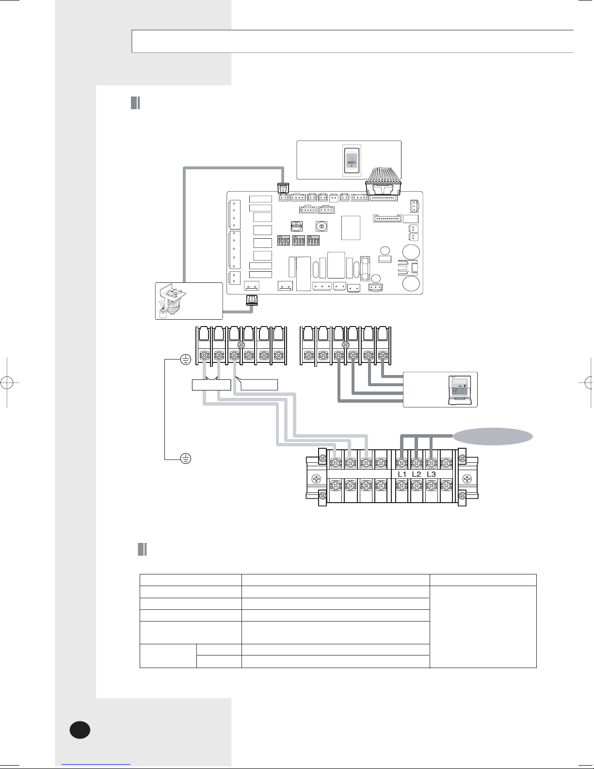
E-13
1(L)
2(N)
Vc Vc Vw Vw F1 F2 V1 V2 F3 F4
F1 F2
Receiver &
Display Unit
(Optional)
Float Switch
Drain Pump
(Optional)
Wired
Remote
Controller
MAIN PCB
3ø380 - 415V~, 50H
z
Communication
Power
MAIN POWER
Indoor Unit
Outdoor Unit
The following electrical characteristics must be respected.
MODEL
Power
Circuit breaker
Indoor unit power cable
Communication cable
Wired remote controller power
& communication cable
Power cable
20m or less
50m or less
DH48GTA(X), DH60GTA(X), DC48GTA(X), DC60GTA(X)
3ø 380-415V~, 50Hz
20A
1.25mm
2
(CV, 3 wire)
0.75~1.0mm2(CV, 2 wire)
The power cables are not
supplied with the air
conditioner.
The user should purchase
them separately.
0.5~0.75mm
2
(CV, 2 wire)
2.0mm
2
(CV, 5 wire)
2.5mm2(CV, 5 wire)
Note
Cable Specifications
Wiring Diagram (DH48GTA, DH60GTA, DC48GTA, DC60GTA)
E-14
Connecting the Connection Cord (Continued)
1(L)
2(N)
3(C)
Vc Vc
F1 F2 V1 V2 F3 F4
3(C)2(N)1(L)
Receiver &
Displ
ay Unit
(Option
al)
Float Switch
Dra
in Pump
(Option
al)
Wired
Remo
te
Controller
MAIN PCB
Power
3ø 220V~, 60H
z
MAIN POWER
Indo
or
Unit
Outdo
or Unit
Wiring Diagram (DC48FTVA,DC60FTVA)
Signal
The following electrical characteristics must be respected.
MODEL
Po
we
r
Circu
it breaker
Indo
or
unit power cable
Wired remote controller power
& communication cable
Power cable
20m or less
50m or less
DC48FTVA(X),DC60FTVA(X)
3ø 220V~, 60Hz
30
A
1.2
5mm2(CV, 4 wire)
The power cables are not
suppli
ed with the air
conditio
ner.
The
user should purchase
th
em separately.
0.5~0.7
5mm
2
(CV, 2 wire)
5.5
mm
2
(CV, 4 wire)
8.0
mm2(CV, 4 wire)
Note
Cable Specifications
 Loading...