

Page 1

SAMSUNG
DCS
COMBINED
PROGRAMMING
MANUAL
DCS
DCS COMPACT
for
DCS COMPACT II
DCS-816
DCS-408
DCS-408i
Page 2

Publication Information
Samsung Telecoms reserves the right without prior notice to revise information in
this publication for any reason.
Samsung Telecoms also reserves the right without prior notice to make changes in
design or components of equipment as engineering and manufacturing may warrant.
Disclaimer
Samsung Telecoms is not responsible for errors or problems arising from customers
not installing, programming or operating their Samsung systems as described in this
manual.
Copyright 2001
Samsung Telecoms (UK) Limited
All rights reserved. No part of this manual may be reproduced in any form or by any
means – graphic, electronic or mechanical, including recording, taping, photocopy or
information retrieval system – without express written permission of the publisher of
this material.
Part No.:12623 Version 2.0
Page 3

EU Declaration of Conformity
For other directives relevant to DCS Compact II, DCS-816, DCS-408 and DCS-408i systems,
refer to the Samsung website at:
www.samsung-telecoms.co.uk
Page 4

DCS CONTENTS
COMBINED PROGRAMMING MANUAL NOVEMBER 2001
Contents
Part
1 Introduction to Programming .....................................1–1
1.1 Using this Manual...........................................................................1–1
1.2 Programming Overview ..................................................................1–2
1.3 Programming Levels......................................................................1–2
1.3.1 System Level ............................................................................ 1–2
1.3.2 Customer Level ......................................................................... 1–2
1.3.3 Station Level............................................................................. 1–3
1.4 Keys Used for Programming ..........................................................1–3
1.4.1 Soft Keys .................................................................................. 1–3
1.4.2 Other Keys ............................................................................... 1–3
1.5 Programming Procedures..............................................................1–4
1.5.1 Precautions When Programming ............................................... 1–4
1.5.2 Opening System or Customer Level Programming ..................... 1–4
1.5.3 Opening Station Level Programming.......................................... 1–5
1.5.4 Programmi ng DCS-408 and 408i Systems..................................1–5
2 Program (MMC) List and Default Data ......................2–1
2.1 Program (MMC) List.......................................................................2–1
2.2 Default Data....................................................................................2–3
2.3 System Configuration: Quick Reference...................................... 2–9
3 Special Applications ....................................................3–1
Voice Mail / Auto Attendant Integration...................................................3–2
Individual Station Page............................................................................3–4
CLIP (Calling Line Identification Presentation)........................................3–5
Toll Restriction (Call Barring) Overview ...................................................3–6
S0 Overview.............................................................................................3–8
4 MMCs (in numerical order) ........................................4–1
Page 5

DCS INTRODUCTION
COMBINED PROGRAMMING MANUAL NOVEMBER 2001
Part 1. Introduction to Programming
This manual describes the MMC pro gramming required for the following types of Samsung DCS keyphone system:
• DCS
• DCS Compact (Compact I)
• DCS Compact II
• DCS-816
• DCS-408
• DCS-408i.
In this manual, these systems are referred to as “DCS,” “Compact I (CI),” “Compact II
(CII)," "816," "408" and “408i” respectively. Programming requirements for these system
types are generally the same, but occasionally there are differences. Users of 408 and
408i systems should also read Programming DCS-408 and 408i Systems in section 1.5.4
of this manual. Unless otherwise stated, references to “DCS” include Compact I sy stems.
The different system types are discussed fully in the separate Samsung General De-
scription manuals for each system, where these have been published.
Software Version Numbers
The software version numbers of the systems for which this programming manual is
relevant are: DCS and Compact II=V6.10 or later; 816=V1.09 or later; 408 and
408i=1.04 or later.
1.1 Using This Manual
• It is recommended that you read the whole of Part 1 of this manual which provides a
useful overview to MMC programming procedures.
• For a comprehensive list of available MMCs, see Part 2.
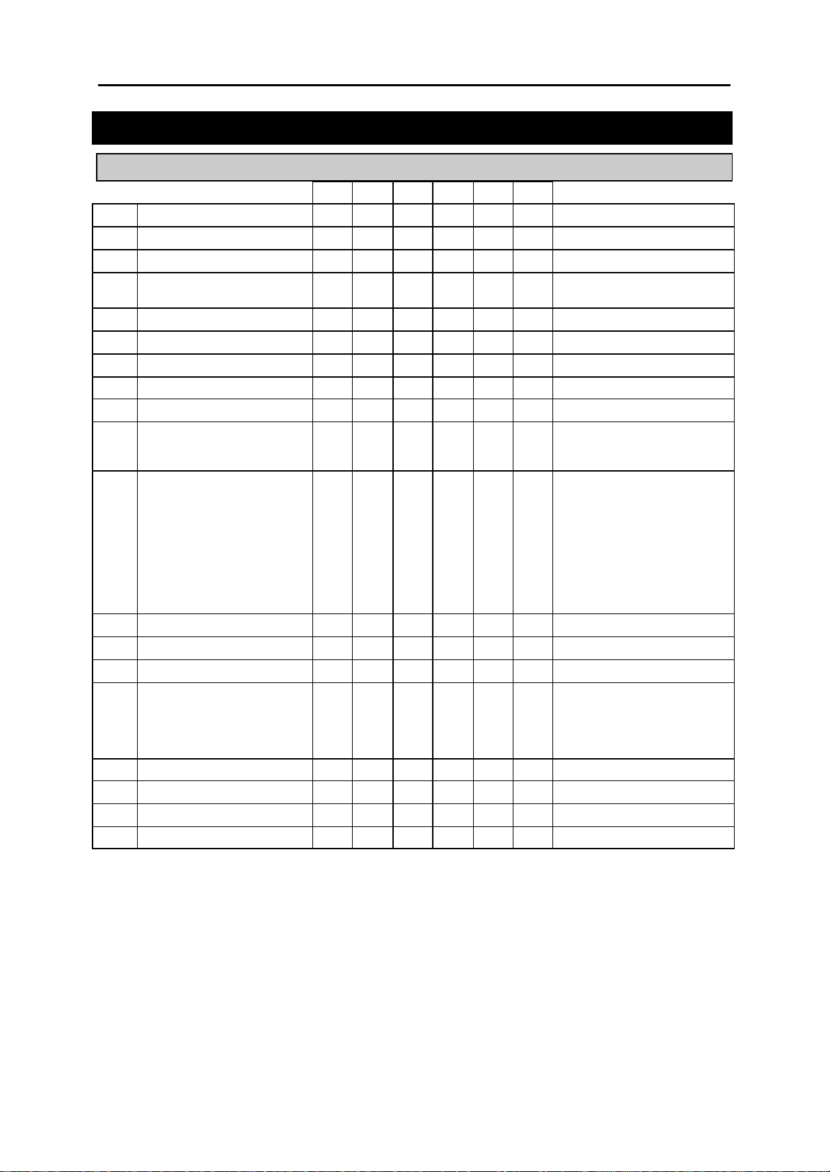
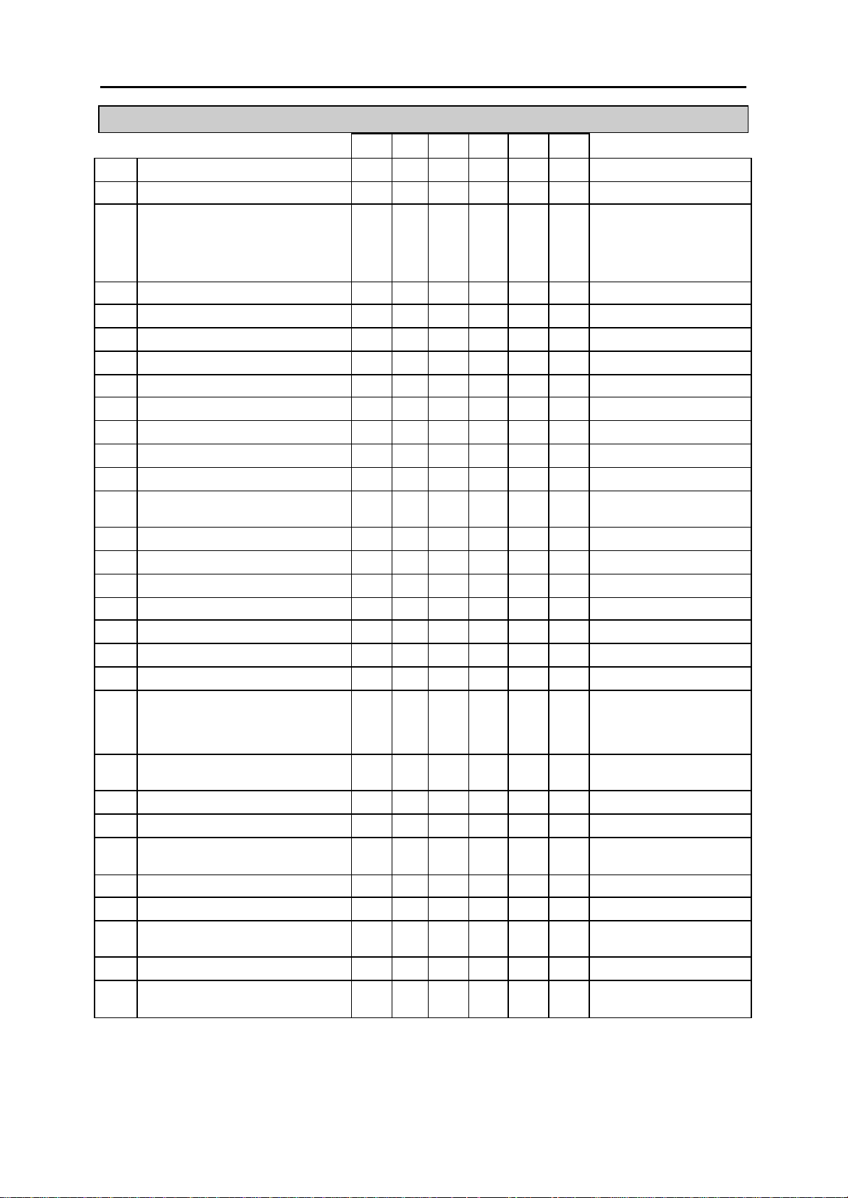
• For quick reference, Part 2 also provides a table listing the default settings for each
MMC and indicating which systems can use each MMC . A “Y” (“Yes”) in the appropriate column indicates that it can be used for that system.
• To quickly check allowed configuration settings for each type of system—number of
trunk group members, card port numbers, and so on—see section 2.3 System Con-
figuration: Quick Reference in Part 2.
• To begin programming, refer to the appropriate MMC(s) in Part 4. Check the se-
lected MMC header bar to make sure the program is available on your system, if
you haven’t already done so.
• Refer to Part 3, Special Applications, for further information on voice mail / auto at-
tendant integration, individual station paging, CLIP (Calling Line Identification Presentation), toll restriction (call barring) and S
0 programming.
1-1
Page 6

DCS INTRODUCTION
COMBINED PROGRAMMING MANUAL NOVEMBER 2001
1.2 Programming Overview
When the keyphone system arrives from the factory it contains default data. This needs
to be customised, using the MMC programs, to suit the customer’s requirements.
MMC stands for Man Machine Code and each MMC is assigned a three-digit code (100,
101, and so on). These MMCs are used to view, create or change customer data on a
display keyphone (called KMMC programming). For example, MMC 601 is used to cr eate a station group; sy stem speed dial numbers are entered in MMC 705; key functions
are assigned to individual keyphones (or “keysets”) using MMC 722; and system dialling codes (such as extension numbers and feature codes) can be changed in MMC
724.
1.3 Programming Levels
There are three levels of programming: System level, Customer level and Station level.
System and Customer levels allow system-wide programming and are under passcode
protection to restrict access. System programming is done by the system installer (or
system technician), usually on a one-off basis, but also to manage any changes in the
customer’s requirements. Customer programming is done by the system administrator,
on a day to day basis, to manage station users’ requirements. Station level programming does not require a passcode, allowing station users to make simple changes to
their keyset features.
To prevent conflicting data from being entered, only one person at a time can enter System or Customer programming. If you attempt to enter programming mode while another keyset is being used for programming, your display shows [xxx PGM MODE]
where “xxx” is the key set extension number of the station in programming mode. While
programming is in progress, normal system operation is not affected.
1.3.1 System Level
This level is entered via MMC 800 and requires the installer’s (technician’s) passcode.
This is the highest level and allows access to all system programs, station programs
and mainte nance programs. The installer (sometimes called the installing technician)
also decides which programs are accessible to the customer (the system administrator)
at Customer level.
• All MMCs are accessible at this level.
1.3.2 Customer Level
This level is entered via MMC 200 and requires the customer’s passcode. It allows access to station programs and system programs permitted by the system installer in
MMC 802. When the system administrator uses the customer passcode to access station programs, data for all stations can be viewed or changed. Changes can be made
either system-wide or to selected keysets. (The system administrator should also refer
to the System Administration manual for their keyphone system if this is available.)
• Accessible MMCs at this level are designated by the installer.
1-2
Page 7
DCS INTRODUCTION
COMBINED PROGRAMMING MANUAL NOVEMBER 2001
1.3.3 Station Level
The system administrator or keyset user can access certain programs at a station without using a passcode. At this level, only data for the selected station can be changed.
You should refer to the instructions provided in the Samsung DCS Keyset User Guide.
• Accessible MMCs at this level are nos. 100–121.
1.4 Keys Used for Programming
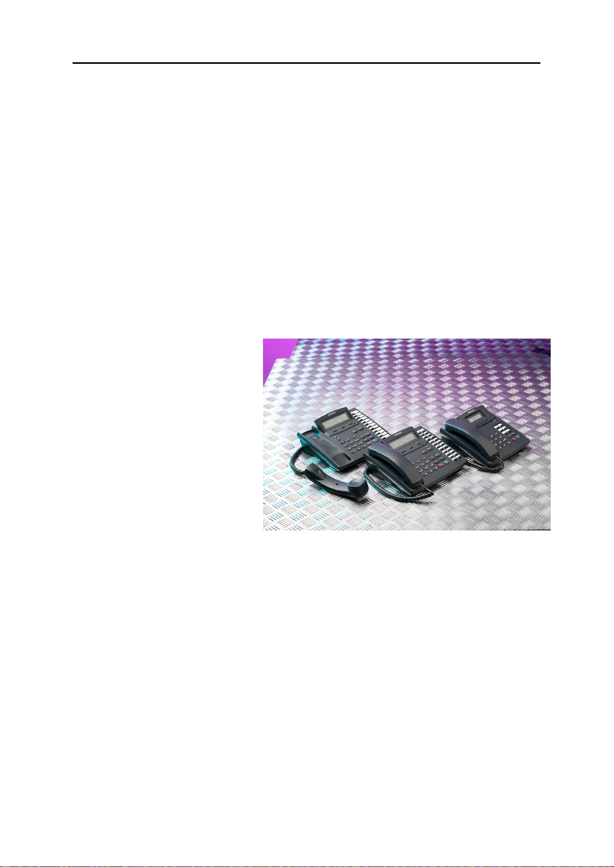
Programming may be done from any 6-button (6B), 12-button (12B) or 24-button (24B)
keyset with a liquid crystal display (LCD). (Refer to the Samsung DCS Keyset User Guide
for a full description of keyset operation.)
1.4.1 Soft Keys
The three keys directly below
the LCD are called soft keys.
The left-hand soft key is designated as the LEFT soft key. This
key is used to save any
changed data while programming, or to move the cu rsor to
the left on the LCD.
The right-hand soft key is designated as the RIGHT soft key.
This key is used to save any
changed data while programming, or to move the cursor to
the right on the LCD.
DCS Euro Display Keysets
1.4.2 Other Keys
The following keys perform special functions:
VOLUME UP (+) / DOWN ( –) Scroll up/down through available options*
KEYPAD Enter data using keys 0 –9 and [, and dial options*
HOLD Clear previous entry
ANS/RLS Select “ALL” option (e.g. to make data apply to all,
rather than selected, stations)
SPEAKER Store data and advance to next MMC
TRSF Enter programming mode or
Store data and exit programming mode
* Note: Many MMCs allow you to dial codes using the keypad to select options quickly. Alternatively, you can press the VOLUME Up and Down keys (+ and – ) to scroll through and select options. Use whic hever method you prefer.
1-3
Page 8
DCS INTRODUCTION
try
y-
select the country and press the RIGHT soft key.
Use the VOLUME Up/Down keys to select YES and press the RIGHT soft key. When
scribed next. The
COMBINED PROGRAMMING MANUAL NOVEMBER 2001
The 6, 12 or 24 extra programmable keys can be set up to perform specific functions
when pressed during normal operation. During programming, some of these keys also
perform other specific functions. This is described in the individual MMC program procedure where applicable.
1.5 Programming Procedures
1.5.1 Precautions When Programming
• The keyset must be on-hook (handset down) to allow programming.
• Programming is available on any digital keyset with an LCD.
• Programming is available only on digital telephones (not analogue ones).
• If ‘INVALID DATA’ appears in the LCD while programming, you should re-enter the
correct data.
• When you have successfully completed an entry, the LCD automatically changes for
the next step.
• Programming halts if you have not pressed a key for a certain period of time (30 se conds by default, but this can be changed).
• Programming halts if you pick up the handset while programming.
• If you pick up the handset while programming, or the telephone plug is pulled out,
any new data shown in the LCD are saved.
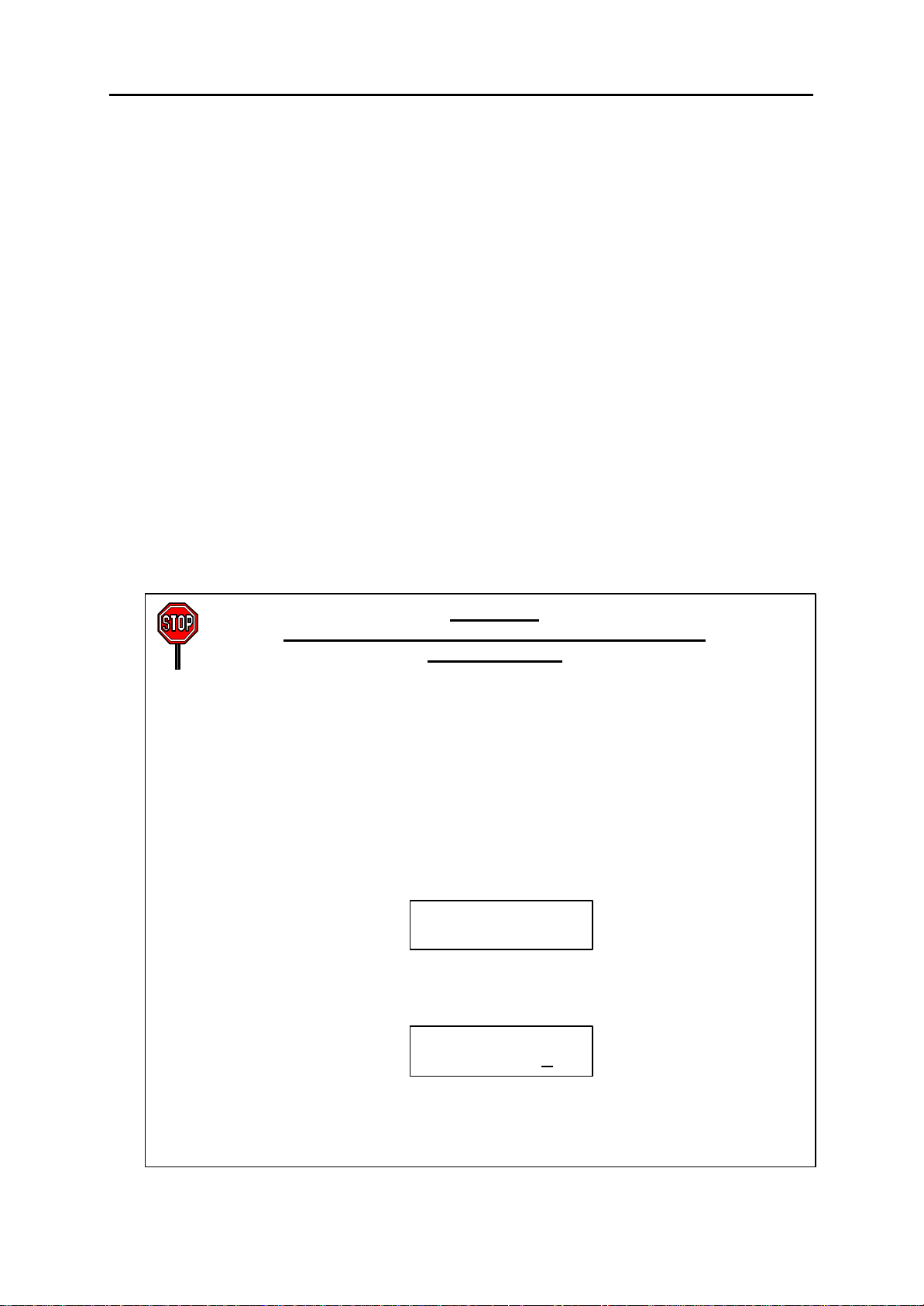
IMPORTANT
When installing and programming a ‘default’ system
for the first time:
The system requires that you select the correct software version for your coun
(e.g. by selecting “UK”) before you can do any other programming via either a ke
phone (KMMC programming) or a PC (PCMMC programming).
To select the country:
1. Press the TRSF key.
2. Enter 800 followed by the default passcode (4321)
The system sounds a warning and displays on the keyset:
Use the VOLUME Up/Down keys to
The keyset displays:
ENABLE TECH. PROG
SELECT COUNTRY
DEFAULTING SYSTM
ARE YOU SURE?NO
defaulted to the correct version, you can open programming as de
country version selected can be changed in MMC 812, Select Country.
1-4
Page 9

DCS INTRODUCTION
COMBINED PROGRAMMING MANUAL NOVEMBER 2001
1.5.2 Opening System or Customer Programming
To open programming:
1. Press the TRSF key.
2. Enter the MMC program number 200 (for Customer level programming) or 800 (for
System level programming).
3. Enter the relevant passcode.
4. Press key 1 (or use the VOLUME Up or Down key) to select ‘ENABLE’.
5. Press the SPEAKER key to have the program selection mode appear (or press the
TRSF key to halt programming).
6. Enter the MMC number, or select the program number with the Up or Down key and
press the SPEAKER key.
When opening system programming, you are advised to check MMC 812 (Select Country) to ensure that the correct country has been selected before you do any other programming.
Carefully follow the instructions given with each MMC to program your system correctly.
1.5.3 Opening Station Level Programming
To open programming:
1. Press the TRSF key.
2. Enter the MMC program number.
Carefully follow the instructions given with each MMC to program your system correctly.
1.5.4 Programming DCS-408 and 408i Systems
Although physically similar in appearance, the “408” and “408i” are different systems and
may have different programming requirements and features. For example, the 408i supports ISDN whereas the 408 does not. Thus, an MMC relevant to one system may not be
relevant to the other. Similarly, where an MMC relates to both systems, some features
available on the 408i system may not be available on the 408 system, and vice versa.
This will be indicated in the MMC description, where appropriate.
These systems also differ significantly from all other keyphone systems, both in size and
physical appearance. In comparison with other systems, when programming your 408 or
408i:
• Extension, group and trunk numbers are two digits by default (e.g. extension 21,
trunk 71, etc). All other systems use 3-digit numbers by default (e.g. extension 201,
trunk 701, etc).* Examples of programming shown in this manual use 3-digit numbers for convenience only.
(*Unless changed by the system installer in MMC 724.)
• You can set up to four ‘Normal’ station groups. Group types AA, VM/AA and UCD
are not permitted.
• Only two trunk groups, 8 and 9, are available. (All other systems support groups 9
and 80–82.)
1-5
Page 10

DCS MMC LIST
COMBINED PROGRAMMING MANUAL NOVEMBER 2001
Part 2. Program MMC List & Default Data
2.1 Program (MMC) List
100: STATION LOCK 317: ASSIGN STATION/STATION USE
101: CHANGE USER PASSCODE 318: DISTINCTIVE RING
102: CALL FORWARD 319: BRANCH GROUP
103: SET ANSWER MODE 400: CUSTOMER ON/OFF PER TRUNK
104: STATION NAME 401: CO/PBX LINE
105: STATION SPEED DIAL 402: TRUNK DIAL TYPE
106: STATION SPEED DIAL NAME 403: TRUNK TOLL CLASS
107: KEY EXTENDER 404: TRUNK NAME
108: STATION STATUS 405: TRUNK NUMBER
109: DATE DISPLAY 406: TRUNK RING ASSIGNMEN T
110: STATION ON/OFF 407: FORCED TRUNK RELEASE
111: KEYSET RING TONE 408: ASSIGN TRUNK MUSIC ON HOLD SOURCE
112: ALARM REMINDER 409: TRUNK STATUS READ
113: VIEW MEMO NUMBER 410: ASSIGN DISA TRUNK
114: STATION VOLUME 411: ASSIGN E1 SIGNAL TYPE
115: SET PROGRAMMED MESSAGE 412: ASSIGN TRUNK SIGNAL
116: ALARM AND MESSAGE 414: MPD/PRS SIGNAL
119: SET CLIP DISPLAY 415: REPORT TRUNK ABANDON DATA
121: KEYSET LANGUAGE 416: ASSIGN AC15 TRANSLATION
200: OPEN CUSTOMER PROGRAMMING 417: PRI CRC4 OPTION
201: CHANGE CUSTOMER PASSCODE 418: CARD RESTART
202: CHANGE FEATURE PASSCODES 419: BRI OPTION
203: ASSIGN UA DEVICE 420: PRI OPTION
204: COMMON BELL CONTROL 421: MSN DIGIT
205: ASSIGN LOUD BELL 422: ASSIGN TRUNK COS
206: BARGE-IN TYPE 423: S/T MODE
207: ASSIGN VM/AA PORT 424: S0 MAPPING
208: ASSIGN RING TYPE 426: TRUNK GAIN CONTROL
209: ASSIGN ADD-ON MODULE 427: R2MFC SIGNAL
210: CUSTOMER ON/OFF 428: ASSIGN TRUNK/TRUNK USE
211: DOOR RING ASSIGNMENT 500: SYSTEM-WIDE COUNTERS
212: ALARM RINGING STATION 501: SYSTEM-WIDE TIMERS
213: ALARM MESSAGE 502: STATION-WIDE TIMERS
214: DISA ALARM RINGING STATION 503: TRUNK-WIDE TIMERS
215: VOICE DIALLER OPTION S 504: PULSE MAKE/BREAK RATIO
216: VOICE DIALLER ASSIGNMENTS 505: ASSIGN DATE AND TIME
217: CCC OPTION 506: TONE CADENCE
219: COMMON RELAY SERVICE TYPE 507: ASSIGN AUTO NIGHT TIME
220: ISDN SERVICE TYPE 508: CALL COST
300: CUSTOMER ON/OFF PER STATION 509: C.O. TONE CADENCE
301: ASSIGN STATION COS 510: SLI RING CADENCE
302: PICKUP GROUPS 511: MW LAMP CAD
303: ASSIGN BOSS/SECRETARY 512: ASSIGN HOLIDAY
304: ASSIGN STA TION/TRUNK USE 600: ASSIGN OPERATOR GROUP
305: ASSIGN FORCED CODE 601: ASSIGN STATION GROUP
306: HOT LINE 602: STATION GROUP NAME
308: ASSIGN BACKGROUND MUSIC SOURCE 603: ASSIGN TRUNK GROUP
309: ASSIGN STATION MUSIC ON HOLD 604: ASSIGN STATION TO PAGE ZONE
310: LCR CLASS OF SERVICE 605: ASSIGN EXTERNAL PAGE ZONE
311: ASSIGN SIM PARAMETER 606: ASSIGN SPEED BLOCK
312: ALLOW CLIP 607: UCD OPTIONS
313: ASSIGN PIN CODE 608: ASSIGN CLIP REVIEW BLOCK
314: CONFIRM OUTGOING CAL L 700: COPY COS CONTENTS
315: SET RELOCATION 701: ASSIGN COS CONTENTS
316: COPY STATION USABLE 702: TOLL DENY TABLE
2-1
Page 11

DCS MMC LIST
COMBINED PROGRAMMING MANUAL NOVEMBER 2001
703: TOLL ALLOWANCE TABLE 736: ASSIGN AA MOH
704: ASSIGN WILD CHARACTER 737: DECT SYSTEM CODE
705: ASSIGN SYSTEM SPEED DIAL 738: DECT CLEAR REGISTRATION
706: SYSTEM SPEED DIAL BY NAME 739: BSI DOWNLOAD
707: AUTHORISATION CODE 740: STATION PAIR
708: ACCOUNT CODE 741: BSI CARD RESTART
709: PBX ACCESS CODE 742: BSI STATUS
710: LCR DIGIT TABLE 743: DECT BASE STATION (DBS) STATUS
711: LCR TIME TABLE 744: DECT REGISTRATION ON/OFF
712: LCR ROUTE TABLE 745: BSI CARRIER
713: LCR MODIFY DIGIT TABLE 750: VM CARD RESTART
714: DDI NUMBER & NAME TRANSLATION 751: ASSIGN MAILBOX
715: PROGRAMMED STATION MESSAGE 752: AUTO RECORD
716: UK LCR OPTION 753: WARNING DESTINATION
717: PIN CODE 754: VM HALT
718: MY AREA CODE 755: VM ALARM
720: COPY KEY PROGRAMMING 756: ASSIGN VM MOH
721: SAVE STATION KEY PROGRAMMING 757: VM IN/OUT
722: STATION KEY PROGRAMMING 800: ENABLE TECHNICIAN PROGRAM
723: SYSTEM KEY PROGRAMMING 801: CHANGE TECHNICIAN PA SSCODE
724: DIAL NUMBERING PLAN 802: CUSTOMER ACCESS MMC NUMBER
725: SMDR OPTIONS 803: ASSIGN TENANT GROUP
726: VM/AA OPTIONS 804: SYSTEM I/O PARAMETER
727: SYSTEM VERSION DISPL AY 805: TX LEVEL & GAIN
728: CLIP TRANSLATION TA BLE 806: CARD PRE-INSTALL
730: AA RECORD GAIN 807: VOLUME CONTROL
731: AA RAM CLEAR 808: T1 TRUNK CODING
732: AA TRANSLATION TABLE 809: SYSTEM MMC LANGUAGE
733: AA PLAN TABLE 810: HALT PROCESSING
734: AA MESSAGE MATCH 811: RESET SYSTEM
735: AA USE T ABLE 812: SELECT COUNTRY
2-2
Page 12
DCS DEFAULT DATA
COMBINED PROGRAMMING MANUAL NOVEMBER 2001
2.2 Default Data
Station Programs
DCS CI CII 816 408 408i
100: STATION LOCK Y Y Y Y Y Y ALL STATIONS UNLOCKED
101: CHANGE USER PASSCODE Y Y Y Y Y Y ALL STATION PASCODES=1234
102: CALL FORWARD Y Y Y Y Y Y ALL STATION=0 (FWD CANCEL)
103: SET ANSWER MODE Y Y Y Y Y Y
104: STATION NAME Y Y Y Y Y Y NONE
105: STATION SPEED DIAL Y Y Y Y Y Y NONE
106: STATION SPEED DIAL NAME Y Y Y Y Y Y NONE
107: KEY EXTENDER Y Y Y Y Y Y NONE
108: STATION STATUS Y Y Y Y Y Y SEE MMC 108
109: DATE DISPLAY Y Y Y Y Y Y COUNTRY: WESTERN
110: STATION ON/OFF Y Y Y Y Y Y AUTO HOLD: OFF
111: KEYSET RING TONE Y Y Y Y Y Y SELECTION=5
112: ALARM REMINDER Y Y Y Y Y Y ALARMS SET TO NOTSET
113: VIEW MEMO NUMBER Y Y Y Y Y Y NO MEMOS ENTERED
114: STATION VOLUME Y Y Y Y Y Y RING VOL: 4
115: SET PROGRAMMED MESSAGE Y Y Y Y Y Y NO MESSAGES SELECTED
116: ALARM AND MESSAGE Y Y Y Y Y Y ALARMS SET TO NOTSET
119: SET DISPLAY Y Y Y Y N Y NAME FIRST
121: KEYSET LANGUAGE Y N Y Y Y Y ENGLISH
ALL KEYSETS ‘RING’
RING FREQUENCY DEFAULT=5
CLOCK: 24-HOUR
DISPLAY: LOWERCASE
AUTO TIMER: ON
HEADSET MODE: OFF
HOT KEYPAD: ON
KEY TONE: ON
PAGE REJOIN: ON
RING PREFERENCE: ON
CALL COST: OFF
AME BGM: OFF
AME PSWD: OFF
OFF HOOK RING VOL: 4
HANDSET VOL: 4
SPEAKER VOL: 13
BGM VOL: 13
2-3
Page 13
DCS DEFAULT DATA
COMBINED PROGRAMMING MANUAL NOVEMBER 2001
System Programs
200: OPEN CUSTOMER PROGRAMMING Y Y Y Y Y Y CLOSED (DISABLED)
201: CHANGE CUSTOMER PASSCODE Y Y Y Y Y Y PASSCODE =1234
202: CHANGE FEATURE PASSCODES Y N Y Y Y Y DAY/NIGHT=0000
203: ASSIGN UA DEVICE Y Y Y Y Y Y NONE
204: COMMON BELL CONTROL Y Y Y Y Y Y CONTINUOUS
205: ASSIGN LOUD BELL Y N Y Y Y Y UNASSIGNED
206: BARGE-IN TYPE Y Y Y Y Y Y NO BARGE IN
207: ASSIGN VM/AA PORT Y Y Y Y Y Y NORMAL PORT
208: ASSIGN RING TYPE Y Y Y Y Y Y ICM RING
209: ASSIGN ADD-ON MODULE Y Y Y Y N N NONE FOR MASTER
210: CUSTOMER ON/OFF Y Y Y Y Y Y SEE MMC 210
211: DOOR RING ASSIGNMENT Y Y Y Y Y Y STATION GROUP 500 (or 50)
212: ALARM RINGING STATION Y N Y N N N ALL SENSORS RING 500
213: ALARM MESSAGE Y N Y N N N NONE
214: DISA ALARM RINGING STATION Y Y Y Y Y Y DAY/NIGHT=500 (or 50)
215: VOICE DIALLER OPTIONS Y Y Y N N N 2CH-7USER-20BIN
216: VOICE DIALLER ASSIGNMENTS Y Y Y N N N NONE
217: CCC OPTION N Y N N N N NONE
219: COMMON RELAY SERVICE TYPE N N Y Y Y Y SEE MMC 219
220: ISDN SERVICE TYPE Y Y Y Y N Y VOICE
300: CUSTOMER ON/OFF PER STATION Y Y Y Y Y Y STN CALL PRT : OFF
301: ASSIGN STATION COS Y Y Y Y Y Y DAY CLASS = 1
302: PICKUP GROUPS Y Y Y Y Y Y ALL STATIONS GROUP 1
303: ASSIGN BOSS/SECRETARY Y Y Y Y Y Y NONE
304: ASSIGN STATION/TRUNK USE Y Y Y Y Y Y DIAL = YES
305: ASSIGN FORCED CODE Y Y Y Y Y Y NONE
306: HOT LINE Y Y Y Y Y Y NONE
308: ASSIGN BACKGROUND MUSIC
SOURCE
309: ASSIGN STATION MUSIC ON HOLD Y Y Y Y Y Y NONE
310: LCR CLASS OF SERVICE Y Y Y Y Y Y LEAST COST ROUTING
DCS CI CII 816 408 408i
Y Y Y Y Y Y NONE
DISA ALARM=5678
ALARM CLR=8765
AA RECORD=4321
DECT (BSI) REGISTER =4321
DAY/NIGHT
FWD DLY USE : OFF
OTHER FEATURES SET TO
ON
NIGHT CLASS = 1
ANS = YES
COS 1
2-4
Page 14

DCS DEFAULT DATA
COMBINED PROGRAMMING MANUAL NOVEMBER 2001
DCS CI CII 816 408 408i
311: ASSIGN SIM PARAMETER Y N N N N N SIM TYPE = DTE
312: ALLOW CLIP Y Y Y Y N Y RCV=YES, SEND=YES,
313: ASSIGN PIN CODE N Y N N N N ALL STATIONS ARE CODE
314: CONFIRM OUTGOING CALL Y N Y Y Y Y NONE
315: SET RELOCATION Y N Y Y Y Y NONE
316: COPY STATION USABLE Y N Y Y N N NONE
317: ASSIGN STATION/STATION USE Y N Y Y N N DIAL=YES
318: DISTINCTIVE RING Y N Y Y Y Y T=F-STN, C=F-STN
319: BRANCH GROUP – – – – – – NOT USED IN UK
400: CUSTOMER ON/OFF PER TRUNK Y Y Y Y Y Y 1A2 EMULATE: OFF
401: C.O./PBX LINE Y Y Y Y Y Y ALL TRUNKS C.O. LINE
402: TRUNK DIAL TYPE Y Y Y Y Y N ALL TRUNKS DTMF
403: TRUNK TOLL CLASS Y Y Y Y Y Y ALL TRUNKS F-STN
404: TRUNK NAME Y Y Y Y Y Y NO NAMES ENTERED
405: TRUNK NUMBER Y Y Y Y Y Y NO NUMBERS ENTERED
406: TRUNK RING ASSIGNMENT Y Y Y Y Y Y ALL TRUNKS DAY/NIGHT:
407: FORCED TRUNK RELEASE Y Y Y Y Y Y NONE
408: ASSIGN TRUNK MUSIC ON HOLD
SOURCE
409: TRUNK STATUS READ Y Y Y Y Y Y SEE MMC 409
410: ASSIGN DISA TRUNK Y Y Y Y Y Y ALL TRUNKS NORMAL
411: ASSIGN E1 SIGNAL TYPE – – – – – – NOT USED IN UK
412: ASSIGN TRUNK SIGNAL Y Y Y N N N IMMEDIATE
414: MPD/PRS SIGNAL Y Y Y Y Y N NONE
415: REPORT TRUNK ABANDON DATA Y Y Y Y N Y REPORT=YES
416: ASSIGN AC15 TRANSLATION Y Y Y N N N UNUSE DID TRANS
417: PRI CRC4 OPTION Y N Y N N N CRC4 ON
418: CARD RESTART Y Y Y Y N Y NONE
Y Y Y Y Y Y TONE
CALL MODE = MANUAL
ANS MODE = MANUAL
AUTO BAUD = ON
DTR CHECK = ON
ECHO = ON
PROTOCOL = V110
SPEED = 9600
CHAR LENGTH = 8 BITS
PARITY = NONE
STOP BIT = 1
INFO=CO Tel
#1
TRUNK INC DND: OFF
TRUNK FORWARD: ON
LCR ALLOW:OFF
DAY/NIGHT
500 (or 50)
2-5
Page 15

DCS DEFAULT DATA
COMBINED PROGRAMMING MANUAL NOVEMBER 2001
DCS CI CII 816 408 408i
419: BRI OPTION Y Y Y Y N Y CHANNEL ANY: YES
420: PRI OPTION Y N Y N N N CHANNEL ANY: YES
421: MSN DIGIT Y Y Y Y N Y NONE
422: ASSIGN TRUNK COS Y Y Y Y Y Y DAY CLASS: 1
423: S/T MODE Y Y Y Y N Y TRUNK
424: S0 MAPPING Y Y Y Y N Y NONE
426: TRUNK GAIN CONTROL Y N Y Y Y Y RX=+0.0 dB, TX=+0.0 dB
427: R2MFC SIGNAL N N N N N N NOT USED IN UK
428: ASSIGN TRUNK/TRUNK USE Y N Y Y N N DIAL=YES
500: SYSTEM-WIDE COUNTERS Y Y Y Y Y Y SEE MMC 500
501: SYSTEM-WIDE TIMERS Y Y Y Y Y Y SEE TABLE OF TIMERS
502: STATION-WIDE TIMERS Y Y Y Y Y Y NO ANS FWD: 015 SEC
503: TRUNK-WIDE TIMERS Y Y Y Y Y Y ANS.BAK TM: 600 MS
504: PULSE MAKE/BREAK RAT IO Y Y Y Y Y N MAKE/BREAK = 33
505: ASSIGN DATE AND TIME Y Y Y Y Y Y FOLLOWS S/W VERSION
506: TONE CADENCE Y Y Y Y Y Y SEE MMC 506
507: ASSIGN AUTO NIGHT TIME Y Y Y Y Y Y NONE
508: CALL COST Y Y Y Y Y Y UNIT COST PER MP: 200
509: C.O. TONE CADENCE N Y N N N N SEE MMC 509
510: SLI RING CADENCE Y Y Y Y Y Y SEE MMC 510
511: MW LAMP CAD Y N Y N N N ON: 1000MS, OFF: 1000MS
512: ASSIGN HOLIDAY Y N Y Y Y Y NONE
600: ASSIGN OPERATOR GROUP Y Y Y Y Y Y DAY/NIGHT: 500 (or 50)
BRI MODE: P-P DDI
DLSEND: OVERLAP
BRI CODING: A-LAW
POWERFEED: NO
PRI MODE: DDI
DLSEND: OVERLAP
NIGHT CLASS: 1
(ALL TRUNKS)
AND VALUES IN MMC 501
DTMF DURATION: 100 MS
FIRST DGT DELAY: 600 MS
CLEARING: 002 SEC
CO SUPV TM: 400 MS
DTMF DURATION: 100 MS
FIRST DGT DELAY: 600 MS
FLASH TIME: 070 MS
NO RING TM: 004 SEC
PAUSE TIME: 003 SEC
PRS DET TM: 000 MS
RNG DET.TM: 300 MS
WINK: 200 MS
MF/DP INT TM: 0800 MS
MFR DLY TM: 000 SEC
PULSES PER SECOND = 10
RELEASE DATE
PENCE
CALL COST RATE: 100%
2-6
Page 16

DCS DEFAULT DATA
COMBINED PROGRAMMING MANUAL NOVEMBER 2001
DCS CI CII 816 408 408i
601: ASSIGN STATION GROUP Y Y Y Y Y Y SEE MMC 601
602: STATION GROUP NAME Y Y Y Y Y Y NONE
603: ASSIGN TRUNK GROUP Y Y Y Y Y Y SEE MMC 603
604: ASSIGN STATION TO PAGE ZONE Y Y Y Y Y Y NO STATIONS ASSIGNED
605: ASSIGN EXTERNAL PAGE ZONE Y Y Y Y Y Y NONE
606: ASSIGN SPEED BLOCK Y Y Y Y Y Y SYSTEM: SEE MMC 606
607: UCD OPTIONS Y Y Y Y N N SEE MMC 607
608: ASSIGN CLIP REVIEW BLOCK Y Y Y Y N Y ONE BIN OF 10 ENTRIES
700: COPY COS CONTENTS Y Y Y Y Y Y NONE
701: ASSIGN COS CONTENTS Y Y Y Y Y Y TOLL LEVEL: ALL COS=A
702: TOLL DENY TABLE Y Y Y Y Y Y ALL ENTRIES=0
703: TOLL ALLOWANCE TABLE Y Y Y Y Y Y ALL ENTRIES=0
704: ASSIGN WILD CHARACTER Y Y Y Y Y Y ALL X, Y, Z=1
705: ASSIGN SYSTEM SPEED DIAL Y Y Y Y Y Y NONE
706: SYSTEM SPEED DIAL BY NAME Y Y Y Y Y Y NO NAMES
707: AUTHORISATION CODE Y Y Y Y Y Y NONE
708: ACCOUNT CODE Y Y Y Y Y Y NONE
709: PBX ACCESS CODE Y Y Y Y Y Y NONE
710: LCR DIGIT TABLE Y Y Y Y Y Y DEPENDS ON S/W VER-
711: LCR TIME TABLE Y Y Y Y Y Y SEE MMC 711
712: LCR ROUTE TABLE Y Y Y Y Y Y SEE MMC 712
713: LCR MODIFY DIGIT TABLE Y Y Y Y Y Y DEPENDS ON S/W VER-
714: DDI NUMBER AND NAME TRANSLA-
TION
715: PROGRAMMED STATION
MESSAGE
716: UK LCR OPTIONS Y Y Y Y Y Y SEE MMC 716
717: PIN CODE N Y N N N N NONE
718: MY AREA CODE – – – – – – NOT USED IN UK
720: COPY KEY PROGRAMMING Y Y Y Y Y Y NONE
721: SAVE STATION KEY PROGRAMMING Y Y Y Y Y Y RESTORE
722: STATION KEY PROGRAMMING Y Y Y Y Y Y SEE MMC 722
723: SYSTEM KEY PROGRAMMING Y Y Y Y Y Y SEE MMC 723
724: DIAL NUMBERING PLAN Y Y Y Y Y Y SEE MMC 724
725: SMDR OPTIONS Y Y Y Y Y Y SEE MMC 725
726: VM/AA OPTIONS Y Y Y Y Y Y SEE MMC 726
Y Y Y Y N Y SEE MMC 714
Y Y Y Y Y Y 20 MESSAGES (10 PRE-
’ALL ZONE’ IS SET
STATIONS: ONE BIN OF 10
ENTRIES
ALL FEATURES (EXCL.
OVERRIDE)=YES
SION
SION
PROGRAMMED) (SEE MMC
715)
2-7
Page 17

DCS DEFAULT DATA
COMBINED PROGRAMMING MANUAL NOVEMBER 2001
DCS CI CII 816 408 408i
727: SYSTEM VERSION DISPLAY Y Y Y Y Y Y INSTALLED CARD VERSIONS
728: CLIP TRANSLATION TABLE Y Y Y Y N Y NONE
730: AA RECORD GAIN Y N Y Y N N +0.0 dB
731: AA RAM CLEAR Y Y Y Y N N NONE
732: AA TRANSLATION TABLE Y Y Y Y N N SEE MMC 732
733: AA PLAN TABLE Y Y Y Y N N SEE MMC 733
734: AA MESSAGE MATCH Y Y Y Y N N MSG INDEX NO.
735: AA USE TABLE Y Y Y Y N N PLAN 01
736: ASSIGN AA MOH Y Y Y Y N N NOT USE
737: DECT SYSTEM CODE Y Y Y N N N AUTH CODE: FFFF
738: DECT CLEAR REGISTRATION Y Y Y N N N FORCED MODE
739: BSI DOWNLOAD Y Y Y N N N NONE
740: STATION PAIR Y Y Y Y N N NONE
741: BSI CARD RESTART Y Y Y N N N NONE
742: BSI STATUS Y Y Y N N N NONE
743: DBS STATUS Y Y Y N N N NONE
744: DECT REGISTRATION ON/OFF Y Y Y N N N DISABLE
745: BSI CARRIER Y Y Y N N N 1111111111
750: VM CARD RESTART Y N Y N N N DOWNLOAD=YES
751: ASSIGN MAILBOX Y N Y N N N ALL STN=YES, ALL GRP=NO
752: AUTO RECORD Y N Y N N N MB=NONE, PORT=NONE
753: WARNING DESTINATION Y N Y N N N DEST=500
754: VM HALT Y N Y N N N NONE
755: VM ALARM Y N Y N N N THRESHOLD=80%
756: ASSIGN VM MOH Y N Y N N N NOT USE
757: VM IN/OUT Y N Y N N N IN/OUT
800: ENABLE TECHNICIAN PROGRAM Y Y Y Y Y Y DISABLE
801: CHANGE TECHNICIAN PASSCODE Y Y Y Y Y Y DEFAULT PASSCODE = 4321
802: CUSTOMER ACCESS MMC NO. Y Y Y Y Y Y SEE MMC 802
803: ASSIGN TENANT GROUP Y N N N N N ALL ASSIGNMENTS TENANT 1
804: SYSTEM I/O PARAMETER Y Y Y Y Y Y SEE MMC 804
805: TX LEVEL AND GAIN Y Y Y Y Y Y SEE MMC 805
806: CARD PRE-INSTALL Y Y Y Y N N NONE
807: VOLUME CONTROL Y Y Y Y Y Y SEE MMC 807
808: T1 TRUNK CODING – – – – – – NOT USED IN UK
809: SYSTEM MMC LANGUAGE Y N Y Y Y Y ENGLISH
810: HALT PROCESSING Y Y Y Y N N NONE
811: RESET SYSTEM Y Y Y Y Y Y NONE
812: SELECT COUNTRY Y N Y Y Y Y NONE
SYSTEM ID: 000
CALL=I
2-8
Page 18
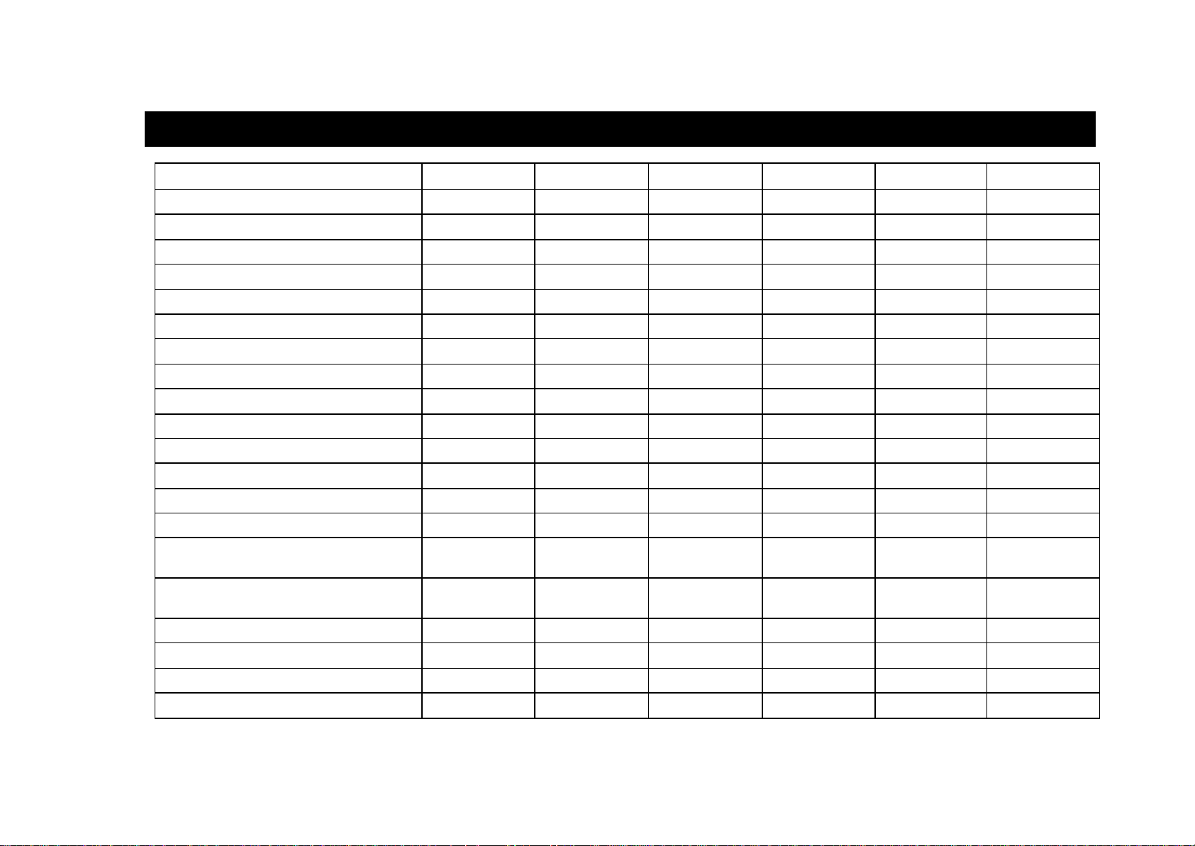
2.3 System Configuration: Quick Reference
Description DCS Compact I Compact II 816 408 408i
AA card port numbers 3951–8 3951–6 381–61 381–4 N/A N/A
AA Translation tables 1 & 2 (entries) 100 100 100 50 N/A N/A
Account codes 500 250 200 200 100 100
Authorisation codes 250 100 100 30 10 10
BGM port numbers 3701–2 371–2 371–2 371–2 371 371
CALL keys (max.) 8 8 5 4 2 2
Classes of Service (COS) 30 30 30 10 4 4
CLIP Translation Table entries 250 250 200 200 N/A 100
Daughterboards (keyset) KSU Any DLI port Motherboard None None None
2-9
DDI entries 200 200 200 50 N/A 20
DECT ports 48 24 24 N/A N/A N/A
LCR Digit Table (max. entries) 500 500 500 300 100 100
MOH port numbers 3701–2 371–2 371–2 371–2 371 371
Operator Groups (part of Stat ion Group) 1 1 1 1 1 1
Operator Group members (sequential / dis-
tributed ring)
Operator Group members (unconditional
ring)
Page zones (no. of internal) 4 4 4 4 2 2
Page zones (no. of external) 4 4 4 1 1 1
Pickup Groups 20 20 20 8 4 4
S0 bus ports 32 32 24 16 None 2
32 30 30 16 8 8
32 30 10 16 8 8
Page 19

2.3 System Configuration: Quick Reference (cont’d)
2-10
Description DCS Compact I Compact II 816 408 408i
Speed dials (total) 1500 500 600 500 300 300
Speed dials (system)(max.) 500 500 500 300 200 200
Station Groups (number of) 30 30 20 10 4 4
Station Group members (sequential / dis-
48 30 30 16 8 8
tributed ring)
Station Group members (unconditional
32 30 10 16 8 8
ring)
Station Group numbers 500–529 500–529 500–519 500–509 50–53 50–53
Trunk Groups (number of) 11 11 11 4 2 2
Trunk Group members 80 10 40 10 4 4
Trunk Group numbers 9, 80–89 9, 80–89 9, 80–89 9, 80–82 9, 8 9, 8
UCD Groups 102 10
2
53 34 N/A N/A
Voice dial card port numbers 3551–2 3551–2 355–6 N/A N/A N/A
Notes:
1
Misc 2 card=381–4, AA card=381 –6, both cards installed=381–90
2
UCD Group can be created from any Station Group 501 –529 (CI) or last 10 Station Groups 520–529 (DCS)
3
UCD Group can only be created from last 10 Station Groups 510 –519
4
UCD Group can only be created from last three Station Groups 507–509
Page 20

DCS SPECIAL APPLICATIONS
COMBINED PROGRAMMING MANUAL NOVEMBER 2001
Part 3. Special Applications
Part 3 provides additional information covering the following topics:
• Voice Mail / Auto Attendant Integration
• Individual Station Page
• CLIP (Calling Line Identification Presentation)
• Toll Restriction (Call Barring) Overview
• S
0 Overview
3-1
Page 21

DCS SPECIAL APPLICATIONS
COMBINED PROGRAMMING MANUAL NOVEMBER 2001
Voice Mail/Auto Attendant Integration
(In-Band / SMDI )
This section focuses mainly on in -band integration. Systems may alternatively accommodate Bellcore standard SMDI—available by setting in MMC 210 (SMDI VMS SET option).
Because of the increased popularity of voice mail and auto attendant use, all DCS systems
include many programmable options to address this demand. The degree of integration
that can be achieved depends on the abilities of the voice mail/auto attendant (VM/AA) system as well as the telephone system.
The following describes the capabilities provided by systems for voice mail via in-band int egration.
Hardware Provisions
• The VM/AA system must be connected to single line circuits on any SLI card.
• Each port is equipped with a dedicated DTMF receiver for detecting DTMF signa lling
from the VM/AA.
• These ports also provide an instant break in loop current when the calling party
hangs up. This is called a disconnect signal.
Software Provisions
• Screened Or Unscreened Transfer
There are no special codes needed to transfer a call. Simply hookflash, receive
transfer dial tone and dial the destination.
• Direct In Lines
Any C.O. call can be assigned to ring at an individual station or a station hunt group
assigned to the VM/AA.
• Calls or Recalls to the Operator
Dialling 0 will always result in a ringback signal. If the operator is busy, the call continues to ring in queue to the operator.
• Message Waiting
A VM/AA port can leave a message at any station or group of stations. The message
waiting indication can be set or cancelled at any station or station group with or without the stations ringing.
3–2
Page 22

DCS SPECIAL APPLICATIONS
COMBINED PROGRAMMING MANUAL NOVEMBER 2001
In-Band Signalling
Systems can be programmed to send the calling station’s extension number after
the voice mail system answers. These DTMF signals may include a leading digit to
indicate the type of call and additional information about the original caller. DTMF
signals may also be substituted for call progress tones to speed up voice mail call
processing. This program allows call forwarding to a mailbox and bypassing of the
main greeting for automatic message retrieval. Blind (unscreened) transfers may be
performed because the recall will be correctly identified.
Note: The effectiveness of this program depends on the ability of the voice mail system to
make use of this information.
• Station Hunt Group With Overflow
Each station group can have an individual overflow destination with an individual
overflow timer. The overflow destination will ring whenever a call to the group is not
answered. If the voice mail system becomes inoperative, calls are automatically
routed to the overflow destination.
• Internal Call Forwarding to Voice Mail
This option in MMC 300 provides the ability to allow or deny call forwarding of internal calls to voice mail. This feature conserves disk drive space by only storing calls
originating outside the system.
• One-Touch Voice Mail Access
One-touch speed dial keys can be programmed to automatically dial, log into and retrieve messages from voice mail.
• Call Progress Tones
The only tones sent to a VM/AA port are dial tone, busy and ringback. To eliminate
confusion, busy tone is substituted for DND or error tones on voice mail ports only.
3–3
Page 23

DCS SPECIAL APPLICATIONS
COMBINED PROGRAMMING MANUAL NOVEMBER 2001
Individual Station Page
Keyphone systems were not designed to permit page announcements to individual keysets.
However, a forced auto answer key (FAUTO) can be used to do this.
1. Program a keyset for RING in MMC 103.
2. Assign a FAUTO key (in MMC 722) to each keyset that is allowed to page individual
keysets.
3. Call another station. When you hear ringback tone, press the FAUTO key. The ringing
will stop and an Auto Answer call is set up.
Note: To prevent the use of this feature from getting out of control, only assign FAUTO keys to those
keysets needing to page individual keysets.
3–4
Page 24

DCS SPECIAL APPLICATIONS
low the
COMBINED PROGRAMMING MANUAL NOVEMBER 2001
CLIP
(Calling Line Identification Presentation)
Hardware Provisions
ISDN trunk cards.
Software Provisions
The MMCs related to CLIP are listed below with a short description of their uses. They are listed
in the recommended order in which they should be programmed. This sequence is suggested
so that the installer/technician gets a better understanding of how the feature works. There is no
technical reason to strictly follow this sequence.
l MMC 312
(ALLOW CLIP)
l MMCs 722 and 723
(STATION & SYSTEM KEY
PROGRAMMING)
l MMC 728
(CLIP TRANSLATION TABLE)
l MMC 725
(SMDR OPTIONS)
l MMC 119
(SET CLIP DISPLAY)
l MMC 501
(SYSTEM-WIDE TIMERS)
Used to determine which keysets are allowed to receive CLIP displays.
It is strongly recommended that all keysets allowed
CLIP in MMC 312 are programmed with a CLIP key
using this MMC.
Allows for the creation of a list of names that correspond to numbers received from the Central Office
(C.O.). These names will be displayed when a call
rings in that has NUMBER ONLY data provided by the
C.O.
Provides the ability to print CLIP data and abandoned
calls on the Station Message Detail Recording
(SMDR) re port.
Station users can determine what CLIP data is displayed when a call rings at the user’s station.
You may need to adjust the CLIP DISPLAY timer. This
is the length of time that CLIP data is displayed at u sers’ stations after the CLIP key is pressed.
l MMC 415
(REPORT TRUNK ABANDON
DATA)
l MMC 608
(ASSIGN CLIP REVIEW BLOCK)
l MMC 701
(ASSIGN COS CONTENTS)
l MMC 724
(DIAL NUMBERING PLAN)
Used to determine which trunks will record data in the
Call Abandon list and print with an Abandon “A” flag
on the SMDR report.
Used to assign CLIP Review blocks to keysets to allow the user to review CLIP data for previous calls
All CLIP features are included in this MMC so that the
system installer can allow or deny them.
CLIP features are included in this MMC to al
system installer to assign an access code where necessary.
3–5
.
Page 25

DCS SPECIAL APPLICATIONS
COMBINED PROGRAMMING MANUAL NOVEMBER 2001
Toll Restriction (Call Barring)
Overview
The system allows each station to be assigned a class of service (COS) for day and night
modes. Into this COS is brought the dialling restrictions to be applied to each station. Dialling restrictions are applied in MMC 702 (Toll Deny Table) and MMC 703 (Toll Allowance
Table).
Eight levels of restriction are available to stations: A, B, C, D, E, F, G and H. Level A imposes no restrictions on station dialling; level H restricts stations to internal calls only; and
levels B to G are programmable. In addition, the Wild Card Table (MMC 704) can be used to
provide more flexibility when programming.
Toll Restriction Ru les
• The Deny Table entries prevent certain numbers being dialled.
• The Allowance Table entries are the ONLY exceptions to the Deny Table entries.
• Listing codes in the Allowance Table with no entries in the Deny Table gives “no
restriction”.
• A wild card in any position in the Deny Table means an exception exists in the Allowance Table for the digits defined by the wild card.
• A wild card at the end of an entry means that more digits may be dialled.
• Never put a single wild card as an entry in the Allowance Ta ble.
• When changing an entry in the BCDEFG status, ALL digits must be entered.
Use of Deny Table
Example
Let’s assume that you want to restrict (bar) the dialling of the following codes to your users:
0860 and 0850 car phone numbers, 0891and 0898 premium rate numbers, 00 International
numbers and 01 STD numbers. You would set up the Deny Table as follows:
TOLL DENY TABLE
ENTRY DIGITS B C D E F G
001 0860 1 0 0 0 0 0
002 0850 1 0 0 0 0 0
003 0891 1 1 1 1 0 0
004 0898 1 1 1 1 0 0
005 00 1 1 0 0 0 0
006 01 1 0 0 1 0 0
Note: The number of entries allowed varies between systems (see MMC 702).
From the above table (“1” means a number is barred):
• Stations with Toll Level B applied will be barred all the codes listed.
• Stations with Toll Level C applied will be barred 0891, 0898 and 00 calls.
• Stations with Toll Level D applied will be barred 0891 and 0898 calls.
• Stations with Toll Level E applied will be barred 0891, 0898 and 01 calls.
3–6
Page 26

DCS SPECIAL APPLICATIONS
COMBINED PROGRAMMING MANUAL NOVEMBER 2001
• Stations with Toll Levels F or G applied will have no restrictions.
Use of Wild Cards and the Allowance Table
The Wild Card Table in MMC 704 appears as follows.
WILD CARD 0 1 2 3 4 5 6 7 8 9 * #
X 0 0 0 0 0 0 0 0 0 0 0 0
Y 0 0 0 0 0 0 0 0 0 0 0 0
Z 0 0 0 0 0 0 0 0 0 0 0 0
The digits 0–9, * and # are values that each of the wild cards X, Y and Z can take. This is
explained later. (You are also unlikely to use any wild card apart from X.)
In the Deny Table, the STD code 01 has been barred to users with a B or E Toll level. It may,
however, be necessary to allow some STD codes to be dialled. For example, the codes
01869, 01993, and 01235 are codes local to Oxford and you may want users in the Oxford
area to have access to these codes, with all other STD codes barred. You can achieve this
using the Wild Card Table and Toll Allowance Table as follows:
Delete entry 006 in the Deny Table and add the following entry:
TOLL DENY TABLE
ENTRY DIGITS B C D E F G
006 01XXX 1 1 1 1 0 0
and in the Toll Allowance Table make the following entries:
TOLL ALLOWANCE TABLE
ENTRY DIGITS B C D E F G
001 01869 1 1 1 1 0 0
002 01993 1 1 1 1 0 0
003 01235 1 1 1 1 0 0
In the above table, any station assigned a Toll level B, C, D or E will be allowed to dial only
01869, 01993 and 01235 numbers, but all other STD codes will be barred. Stations with a
Toll level F or G will be barred from dialling all STD codes.
The changes necessary in the Wild Card Table to implement these requirements are shown
below, where the Wild Card character X represents any value between 0 and 9 (i.e. a “1” is
placed in the field for any value that X is allowed to represent).
WILD CARD 0 1 2 3 4 5 6 7 8 9 # *
X 1 1 1 1 1 1 1 1 1 1 0 0
Y 0 0 0 0 0 0 0 0 0 0 0 0
Z 0 0 0 0 0 0 0 0 0 0 0 0
3–7
Page 27

DCS SPECIAL APPLICATIONS
COMBINED PROGRAMMING MANUAL NOVEMBER 2001
S0 Overview
Contents
Introduction ..................................................................... 3–9
Specifications ..................................................................3–9
PRI ............................................................................ 3–9
BRI............................................................................ 3–9
ISDN Services .......................................................... 3–10
Installation ...................................................................... 3–12
Operation ....................................................................... 3–12
Ports ....................................................................... 3–12
PRI and BRI LT-T Mode ............................................ 3–13
BRI LT-S Mode .........................................................3–13
Features Reference Tables............................................. 3–14
Related Timers ......................................................... 3–14
PRI and BRI LT-T Port ............................................... 3–14
PRI and BRI LT-S Port ............................................... 3–16
Pin Assignment of Connectors ....................................... 3–16
PRI .......................................................................... 3–16
BRI.......................................................................... 3–16
BRI Related MMC Procedure.......................................... 3–18
3–8
Page 28

DCS SPECIAL APPLICATIONS
COMBINED PROGRAMMING MANUAL NOVEMBER 2001
Introduction
In the DCS there are two line cards for ISDN. One is the PRI card containing one Primary
Rate Interface; the other is the BRIN card containing four Basic Rate Interfaces. For Compact (I and II) and 816 systems there are two types of BRI card, one with two BRI access,
the other with four.
The following topics are covered:
Hardware specification of each card
Installation
Operation
ISDN features supported
Note: 1. This document is based on BRI and PRI V2.0 (Nov 4 1996) or later. Therefore, some fe a-
tures are not applicable to the old version.
2. Main CPU software versions required are 4.0 or later (DCS), 2.3 or later (CII), 1.02 or later
(816).
Specifications
PRI
(The PRI option is not applicable to Compact I, 816 or 408/408i systems.)
The card has the following configuration:
Contains one PRI access with RJ-45 interface having 120Ω line termination.
Operates in LT-T mode only. You can only connect to a PSTN ISDN Network Termination
Port (NT).
BRI
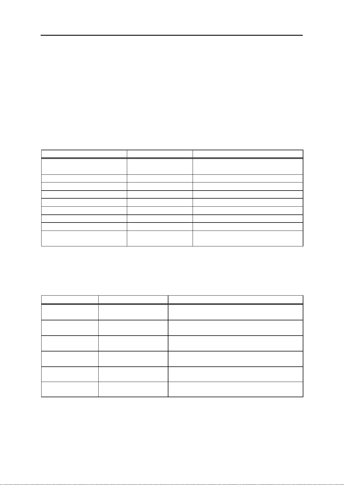
The different types of BRI card are shown in Table 1.
System Card name Number of
BRI access
DCS BRIN
BRI (old)
Compact II 4BRI
2BRI
Compact I &
816
4BRI
2BRI
Table 1 - BRI cards
4
4
4
2
4
2
Power feeding
to S port
YES
NO
YES
YES
NO
NO
Note: The only difference between these cards is the number of access, and power feeding capability.
3–9
Page 29

DCS SPECIAL APPLICATIONS
COMBINED PROGRAMMING MANUAL NOVEMBER 2001
Each BRI / BRIN access has the following features:
Each port operates in either LT-T or LT-S mode. Every setting is done by MMC - there is
no jumper or DIP switch to set. You can connect an NT line or ISDN terminals. (See note,
below.)
For LT-S ports, you can decide whether or not power is supplied to that port by MMC
419.
32 numbers (DCS—range 7801 to 7832) or 24 numbers (Compact II—range 7801 to
7824) are reserved for terminals attached to the LT-S ports. Each number can be assigned to only one port. However, a port can have more than one number. (That is, two
ISDN terminals with the same MSN number cannot exist in different LT -S ports.)
Each S0 bus must be terminated with a 100Ω termination resistor. The original BRI cards
did not have this resistor. However, it is fitted to cards manufactured from mid 1997. It is
important that this termination is present on each installation, and should be checked by
the installer.
Note: 1. In BRI, LT -T and LT-S mode can be selected only by MMC programming. However, you
should connect the Tx and Rx cable pair from the MDF correctly. Tx and Rx connections are
reversed between LT-T and LT-S mode (see Table 15).
2. If you are connecting a T0 port to an NT, take care if there is a termination present some-
where other than on the BRI card on the bus.
ISDN Services
Outgoing calls when origination party is non-S 0 terminal
When an extension seizes an ISDN TRK or S0 terminal attached to the system, the ISDN
bearer capability (BC) and high layer compatibility (HLC) will be coded as in Table 2.
ORIGINATION BC HLC
DGP (Digital keyphone) Speech Telephony
SLT (ICM/CO ring in MMC 208) 3.1 kHz Audio Telephony
SLT (DATA ring in MMC 208) 3.1 kHz Audio Telephony
Table 2 - Coding of BC/HLC when an extension seizes an
ISDN TRK or S0 terminal
Incoming calls when destination party is non-S0 terminal
When an incoming call is present on the ISDN TRK or S0 port, the call will be accepted if the
following condition is satisfied (Table 3). Calls with other BC or HLC will be rejected.
3–10
Page 30

DCS SPECIAL APPLICATIONS
COMBINED PROGRAMMING MANUAL NOVEMBER 2001
BC HLC DESTINATION
Speech Telephony DGP (Digital keyphone)
SLT (ICM/CO ring in MMC 208)
3.1 kHz Audio Telephony SLT (ICM/CO ring in MMC 208)
3.1 kHz Audio None DGP
SLT (ICM/CO ring in MMC 208)
3.1 kHz Audio Fax G2/3 SLT (DATA ring in MMC 208)
Table 3 - Accepted BC and HLC when destination is a non-S0 terminal
Accepted BC and HLC combinations on the ISDN TRK or S0 port
For calls between S0 and ISDN TRK, the following BC and HLC combinations (Table 4) will
be accepted, regardless of which party is the originator.
BC HLC LLC
Speech Telephony A-law
3.1 kHz Audio Telephony A-law
3.1 kHz Audio none A-law
3.1 kHz Audio Fax G2/3 A-law
Unrestricted Digital Info none none
Unrestricted Digital Info Teletex none
Unrestricted Digital Info OSI none
Unrestricted Digital Info Video New none
Unrestricted Digital Info Mixed none
56 kHz Data none none
V.110 none proper value
V.120 none proper value
Video none none
7 kHz Audio none none
Unrestricted Digital Info Fax G4 Fax G4
Table 4 - Accepted BC and HLC when destination is a non-S0 terminal
Supported bearer capability
Speech, Unrestricted Data, 3.1 kHz Audio, 7 kHz Audio, Video
Supported high layer compatibility
Telephony, G3 Fax, G4 Fax, Mixed Mode, Teletex, Videotex, Telex, OSI.
3–11
Page 31

DCS SPECIAL APPLICATIONS
COMBINED PROGRAMMING MANUAL NOVEMBER 2001
Supported ISDN supplementary services
Service Note
DDI PRI DDI Mode and BRI T P-P DDI
MSN BRI T P-M MSN
CLIP Incoming call and outgoing call
Sub Addressing Sub-address of incoming / outgoing call
AOC
ETSI AOC-D Currency/Unit
ETSI AOC-E Currency/Unit
Italy
Holland
Portugal
Belgium
Table 5 – Supported ISDN supplementary services
Installation
The installation procedure is as follows:
1) Switch off the power to the system.
2) Insert the card in the appropriate slot.
3) Execute MMC 811 (Reset System).
4) Carry out related MMC programming according to your intended use of the card.
5) Run MMC 418 (Card Restart).
Note:
§ In DCS, both BRI and PRI must be installed in the Basic Key Service Unit (not the Expansion
Cabinet).
§ The PRI card must be installed in the first slot with the next even-numbered slot empty.
§ 100Ω line termination may not be present on the BRI card. If not, termination should be provided
somewhere outside the BRI card.
§ In BRI, LT-T and LT-S mode can be selected only by MMC programming. However, you should
connect the Tx and Rx cable pair from MDF correctly. Tx and Rx connections are reversed between LT-T and LT-S mode (see Table 15).
Operation
Ports
After installation, the system allocates a port number to each B-channel in exactly the same
way as the analogue trunk case. Thus, a BRI will be assigned eight port numbers, while a
PRI will be assigned 30.
Note: To avoid confusion, the words "port" and "access" are used here with different meanings. "Port"
is used to specify one B-channel, while "access" specifies one BRI span which consists of two Bchannels and one D-channel.
3–12
Page 32

DCS SPECIAL APPLICATIONS
COMBINED PROGRAMMING MANUAL NOVEMBER 2001
PRI & BRI LT -T Mode
Making an outgoing call
Overlap sending
You can seize a port by dialling the port number (e.g. 701). When you see SETUP ACK displayed on your keyset, you can dial the destination number.
Enblock sending
You can make a call through the enblock sending mode port by diallin g the port number
and the destination number followed by #.
Incoming call routing
This depends on the mode of BRI/PRI set by MMC 419/420. See Table 6.
Operational mode Associated table Note
PRI NOR
BRI P-P NOR
BRI P-M NOR
PRI DDI
BRI P-P DDI
BRI P-M NOR MMC 421
Table 6 - Incoming call routing according to MMC 419/420
MMC 406
"TRK RING"
MMC 712
"DDI TABLE"
"MSN DIGIT"
This table has global meaning applied to the ports set to DDI
Same as above
A table is required for each BRI
access
BRI LT -S Mode
Note: All of the following examples are valid only after programming with the appropriate MMC. Refer
to Part 4 of this manual.
Making a call from a DCS subscriber (DGP/SLT) to an ISDN terminal attached to LT-S port
To call a terminal attached to an LT -S port, dial the MSN of the terminal. If a terminal with
MSN of 7803 is attached to 703, and you dialled 7803, a SETUP message will be sent out
through 703 with calling party number of 7803. All terminals with MSN of 7803 will alert.
Alternatively, to call a terminal (or terminals), dial the port number. This time the calling
party number of the SETUP message is vacant. All the terminals attached to that port will
alert, with no regard to MSN number.
In the above cases, dial is always sent in enblock mode.
Caution
When making a call from an S0 terminal, take care with the CLI number. It is usually sent when
the call is made, and if that number is not registered in MMC 424 the system will disconnect
the call.
Making a call from a terminal attached to LT-S port to a DCS subscriber (DGP/SLT)
To call a DCS subscriber from an ISDN terminal, dial the number you want to call. It is of no
concern to the BRI card whether the terminal sends the number in enblock or overlap
mode.
Making a call from a terminal attached to LT-S port to a remote terminal through a TRK
Dial the TRK number followed by the destination number. ISDN TRK and analogue TRK operate in the same way as seen from a terminal. When calling through an ISDN TRK there
3–13
Page 33
DCS SPECIAL APPLICATIONS
COMBINED PROGRAMMING MANUAL NOVEMBER 2001
is no relationship or restriction between the dial sending mode of the terminal and the ISDN
TRK. (DATA calls must use an ISDN TRK.)
Routing an incoming call to the terminals attached to LT-S port
Incoming calls are routed according to the properties of the selected TRK. Routing is controlled by the MMC tables. You can put a terminal number into the DDI, MSN or TRUNK
RING table as a destination, with or without a wild card digit. You can then answer the incoming call from the terminal.
Features Reference Tables
Tables 7 and 8 explain briefly whi ch system features are applicable to ISDN cards.
Related Timers
Feature Implemented Note
ATT Recall Time YES You can check the version of BRI or
PRI
C.O. - C.O. Disconnect NO Only for analogue trunk
Dial Pass Time NO Only for analogue trunk
DISA Disco nnect NO Only for analogue trunk
DISA Lock Out Timer NO Only for analogue trunk
DISA Pass Check NO Only for analogue trunk
First Digit Time
Inter Digit Time
Overlap Inter Digit YES Inter Digit time in overlap send-
ing/receiving
Table 7 – Related DCS timers
Note: These values can be changed in MMC 501 or 503.
PRI and BRI LT-T Port
Call feature capability
Feature Implemented Note
Transfer
NO
Conference YES
Forward YES
SMDR YES
Transfer to remote user through ISDN TRK is
not allowed
Conference with remote user through ISDN
TRK
External Forward - forward to remote user
through ISDN TRK
SMDR report of the calls through ISDN TRK
port
Toll Check YES Toll check through ISDN TRK port
DISA YES Use an ISDN TRK as DISA outgoing line
Table 8 - Call feature abilities of PRI & BRI LT-T
3–14
Page 34

DCS SPECIAL APPLICATIONS
COMBINED PROGRAMMING MANUAL NOVEMBER 2001
MMC dependency
MMC Related Note
MMC 403 Trunk Toll Class YES
MMC 404 Trunk Name NO
MMC 404 Trunk Number NO For an outgoing call, if there is no
matching number in the DDI table this
number will be used as calling party
number
MMC 406 Trunk Ring Assignment YES PRI Mode: NOR
BRI Mode: P-P NOR, P-M NOR
MMC 407 Forced Trunk Release YES
MMC 408 Assign Trunk Music On
YES
Hold Source
MMC 409 Trunk Status Read YES Displays the Cabinet / Slot / Port num-
bers
MMC 410 Assign DISA Trunk YES
MMC 411 E1TRK Signal NO
MMC 412 Assign Trunk Signal NO Only for AC15
MMC 414 MPD/PRS Signal NO Analogue only
MMC 415 Report Trunk Abandon
YES
Data
MMC 416 Assign AC15 Translation NO Only for AC15
MMC 417 PRI CRC4 Option YES
MMC 418 Card Restart YES Restarts PRI or BRI
MMC 419 BRI Option YES
MMC 420 PRI Option YES
MMC 421 MSN Digit YES BRI Mode: P-M MSN
MMC 422 Assign Trunk COS YES
MMC 423 S/T Mode YES Only for BRI
MMC 424 S0 Mapping YES Only for BRI S port
MMC 508 Call Cost NO
MMC 509 C.O. Tone Cadence NO Only for Analogue trunk
MMC 603 Assign Trunk Group YES
MMC 702 Toll Deny Table YES
MMC 703 Toll Allowance Table YES
MMC 714 DDI Table YES PRI: DDI
BRI: P-P DDI
Table 9 – MMC dependency
3–15
Page 35

DCS SPECIAL APPLICATIONS
COMBINED PROGRAMMING MANUAL NOVEMBER 2001
PRI and BRI LT-S Port
Call feature capability
For LT-S ports, only basic call functions are provided - you cannot use other functions
(transfer, forward, hold etc) from an LT -S terminal. However, a DGP can transfer/forward a
call to an LT-S terminal. Other features (conference, hold etc) operate in a similar way.
There is no COS check for an LT -S port.
Pin Assignment of Connectors
PRI
PRI card has one RJ -45 connector with the pin assignments shown in Table10.
Pin Number Assignment
1 Rx
2 Rx
4 Tx
5 Tx
Table 10 - Pin assignments of RJ-45 at customer premises side for PRI
BRI
Champ connector
DCS
Note: Tx and Rx has no polarity.
Function Colour Colour Function
Tx of P1 W/BL BL/W Tx of P1
Rx of P1 W/O O/W Rx of P1
Tx of P2 W/BR BR/W Tx of P2
Rx of P2 W/SL SL/W Rx of P2
Tx of P3 R/O O/R Tx of P3
Rx of P3 R/GR GR/R Rx of P3
Tx of P4 R/SL SL/R Tx of P4
Rx of P4 BK/BL BL/BK Rx of P4
Table 11 - Champ connector pin assignment
(DCS)
3–16
Page 36

DCS SPECIAL APPLICATIONS
COMBINED PROGRAMMING MANUAL NOVEMBER 2001
Compact I
Table 12 - Champ connector pin assignment
(Compact I)
Note: Table 12 is based on expansion slot 1 of Compact I. Tx and Rx has no polarity.
Function Colour Colour Function
Tx of P1 W/BL BL/W Tx of P1
Rx of P1 W/O O/W Rx of P1
Tx of P2 W/GR GR/W Tx of P2
Rx of P2 W/BR BR/W Rx of P2
Tx of P3 W/SL SL/W Tx of P3
Rx of P3 R/BL BL/R Rx of P3
Tx of P4 R/O O/R Tx of P4
Rx of P4 R/GR GR/R Rx of P4
Compact II
Table 13 - Champ connector pin assignment
(Compact II)
Function Colour Colour Function
Tx of P1 SL/P P/SL Tx of P1
Rx of P1 BR/P P/BR Rx of P1
Tx of P2 GR/P P/GR Tx of P2
Rx of P2 O/P P/O Rx of P2
Tx of P3 BL/P P/BL Tx of P3
Rx of P3 SL/Y Y/SL Rx of P3
Tx of P4 BR/Y Y/BR Tx of P4
Rx of P4 GR/Y Y/GR Rx of P4
Note: Table 13 is based on expansion slot 1 of Compact II. Tx and Rx has no polarity.
816
Table 14 - Champ connector pin assignment
(816)
Note: Tx and Rx has no polarity.
Function Colour Colour Function
Tx of P1 W/GR GR/W Tx of P1
Rx of P1 W/BR BR/W Rx of P1
Tx of P2 W/SL SL/W Tx of P2
Rx of P2 R/BL BL/R Rx of P2
Tx of P3 R/O O/R Tx of P3
Rx of P3 R/GR GR/R Rx of P3
Tx of P4 R/BR BR/R Tx of P4
Rx of P4 R/SL SL/R Rx of P4
3–17
Page 37

DCS SPECIAL APPLICATIONS
COMBINED PROGRAMMING MANUAL NOVEMBER 2001
RJ-45 pin assignment for BRI
User Side (LT-T) Pin Number NT Side (LT-S)
Tx 3 Rx
Rx 4 Tx
Rx 5 Tx
Tx 6 Rx
Table 15 - Pin assignment of RJ -45 for BRI
Note: DCS-408 and 408i users should refer to the Installation Manual provided with their system for
details of pin connections for BRI.
Making an RJ -45 connector extension to BRI
As shown in Table 15, LT -S (NT side) and LT-T (User side) have different pin assignments in
RJ-45. You can use the pin assignment tables (11–14) with Table 15 according to the function of the BRI port. You should connect pins with the pins in Table 15 that have the same
name.
Note: RJ-45 sockets come in different styles which look similar. However, pin numbers may be terminated in different places. Therefore, always check the pin numbers on your connectors.
BRI Related MMC Procedure
There are several MMCs related to BRI cards. Because some MMCs have dependencies on
other MMCs, it could become cumbersome to do MMC programming correctly. You should,
therefore, program these MMCs in a pre-defined order, as described in this section. Be sure
to follow this order, or some of the MMC data will be lost.
3–18
Page 38
DCS SPECIAL APPLICATIONS
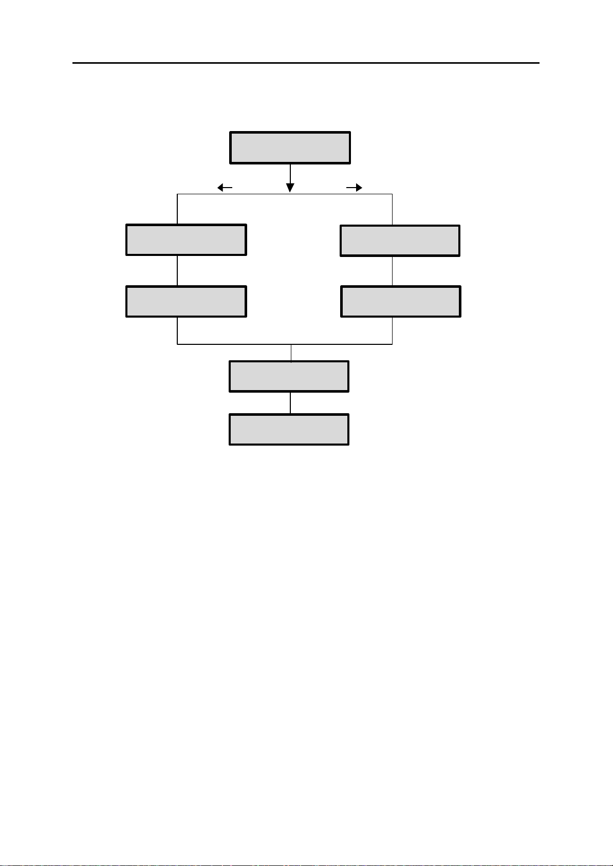
MMC 423
MMC 424
MMC 419
MMC 419
MMC 421
Program MSN in your
MMC 418
COMBINED PROGRAMMING MANUAL NOVEMBER 2001
Order of Programming
Carry out programming as shown in the diagram, below.
S0 Mapping (NOTE 1)
BRI-STN (NOTE 2)
S/T mode
T S
BRI-TRK (NOTE 2)
MSN Digit (NOTE 3)
Card Restart
ISDN terminal (NOTE 4)
Note:
1. This item does not have to be programmed prior to MMC 419 or MMC 418 (because those MMCs
have no effect on this item). However, this item must be preceded by MMC 423.
2. This item displays its name as "BRI-TRK" or "BRI-STN" according to the port setting in MMC 423.
3. This item is only applicable when a BRI access is programmed as P-MP MSN in MMC 419.
4. Only for a STATION port set in MMC 423.
Example of programming a STATION port
Assume that you have a BRI card installed in DCS and its ports are numbered from 701 to
708. You want to use the 4th BRI access (707 and 708) as a STATION port to connect ISDN
terminals. The procedure is:
3–19
Page 39

DCS SPECIAL APPLICATIONS
COMBINED PROGRAMMING MANUAL NOVEMBER 2001
Step 1
Select the functional mode of that port as STATION in MMC 423 (S/T Mode). You
can set either 707 or 708 to STATION.
Step 2
Choose whether you want to supply power to that BRI access or not. If you do, set
the POWER FEED option to YES in MMC 419.
Step 3
Restart the BRI card by executing MMC 418 (Card Restart) so that the changes you
made can take effect.
Step 4
Program MMC 424 (S0 Mapping) to map an ISDN number into a port. You must also
input the "mapped number" as MSN to the ISDN terminals connected to that BRI access. If you mapped 7807 into 707, you must set the MSN of the terminals connected to 707 (or 708) to 7807.
Now, if you dial 7807 from a keyphone (DGP), a SETUP message will be sent out
through 707 (or 708) with the called party number of 7807. There can be a number
of terminals connected to 707 (or 708) but only terminals with MSN of 7807 will alert.
Alternatively, if you dial 707 (or 708) from a DGP, SETUP message will be sent out
through 707 (or 708) without the called party number. All terminals connected to 707
(or 708) will alert.
BRI Access
In MMCs 419, 421, 423 and 424, which are related to BRI cards, you can see the "port"
number displayed as "7x(x)". Each port stands for a B-channel. Thus, two adjacent ports
make up a BRI access. You need only change the settings for one of the two ports for that
BRI access.
For example, you may see port 709 and 710 are displayed respectively in the MMCs, but
these ports are for the same BRI access. If you change settings for 709 you also change
settings for 710, and vice versa.
3–20
Page 40

DCS MMC PROGRAMS
COMBINED PROGRAMMING MANUAL NOVEMBER 2001
Part 4. MMC Programs
This part contains all the MMC programs provided for your keyphone system, presented in
numerical order.
• The procedure described here for a particular MMC may be slightly different on your
system and some LCD displays may not be exactly as shown. For exam ple, port
numbers may be different for the system you are programming. Refer to the section
System Configuration: Quick Reference in Part 1 for the relevant options for your system.
Also, 408 and 408i systems employ 2-digit extension and group numbers by default,
unlike other systems which use 3-digit numbers by default. (These dialling number
plans can be changed by the system installer using MMC 724.)
Remember that the displays shown for each MMC in this manual are provided
as examples, and should be used for guidance only.
• To identify which MMCs apply to your system, either refer to the MMC lists at the
beginning of this manual, or locate the relevant MMC page here and refer to the tick
box beneath the title: a tick (3) next to the system name indicates it is applicable; a
cross (7) means it is not.
• The procedure described for each MMC assumes you are the installer or system
administrator with system-wide access via a passcode. However, MMCs 100–121
are also accessible to individual keyset users. If you are programming your own
keyset at Station level, the procedure is different and you should refer to your Sam-
sung DCS Keyset User Guide for details.
• The term “DCS” as used in this manual includes Compact I systems, except where
otherwise indicated.
• Make sure the correct country is first selected (MMC 812) before carrying out any
other programming.
4–1
Page 41
DCS MMC PROGRAMS
COMBINED PROGRAMMING MANUAL NOVEMBER 2001
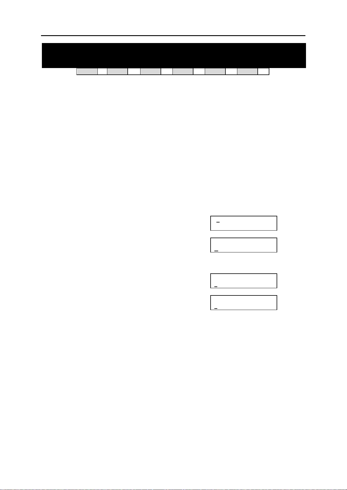
MC: 100 STATION LOCK
DCS
Allows the system administrator to lock or unlock an individual station or all stations simultaneously. The three options are:
0 UNLOCKED Unlocks a locked station.
1 LOCKED OUT Prevents the station from accessing a C.O. line and initiating an ex-
2 LOCKED ALL Prevents the station from initiating any actions.
PROGRAM KEYS
UP & DOWN Used to scroll through options
KEYPAD Used to enter selections
SOFT KEYS Move cursor left and right
SPEAKER Used to store data and advance to next MMC
HOLD Used to clear previous entry
ANS/RLS Used to select ALL
ACTION DISPLAY
1. Open programming and select 100
Display shows
2. Dial station number (e.g., 205)
OR
Use UP and DOWN to select station
and use RIGHT soft key to move cursor
OR
Press ANS/RLS to select all stations [ALL] STN LOCK
3. Enter 0 to unlock, 1 to lock out or 2 to lock all (e.g., 1)
OR
Press UP or DOWN key to make
selection and press RIGHT soft key
to return to step 2
4. Press TRSF to save and exit
OR
Press SPEAKER to save and advance
to next MMC
33
CI
ternal call
33
CII
33
816
33
408i
01] STN LOCK
[2
UNLOCKED
[205] STN LOCK
NLOCKED
U
?
?
[205] STN LOCK
OCKED OUT
L
33
408
33
Default Data: All stations unlocked
Related Items: Station user programming
MMC 100 (Page 1 of 1)
Page 42

DCS MMC PROGRAMS
COMBINED PROGRAMMING MANUAL NOVEMBER 2001
MMC: 101 CHANGE USER PASSCODE
DCS
33
CI
33
CII
33
816
33
408i
33
408
33
Allows the system administrator to reset keyset passcodes to their default value of “1234.” This
MMC cannot display station passcodes; it can only reset them to default.
The passcode is used to lock or unlock the keyset for toll restriction (call barring) override and to
access the DISA feature.
Note:
Default passcodes cannot be used for toll restriction override, DISA access or the walking class of service
function.
PROGRAM KEYS
UP & DOWN Used to scroll through options
KEYPAD Used to enter selections
SOFT KEYS Move cursor left and right
SPEAKER Used to store data and advance to next MMC
HOLD Used to clear previous entry
ACTION DISPLAY
1. Open programming and select 101
Display shows
2. Dial keyset number (e.g., 205)
OR
Use UP or DOWN to scroll through keyset numbers
and press RIGHT soft key to move the cursor right
3. Press HOLD to reset passcode
4. Press TRSF to store and exit
OR
Press SPEAKER to store and advance to next MMC
Default Data: All station passcodes = 1234
Related Items: MMC 100 Station Lock
01] PASSCODE
[ 2
PASSCODE: QQQQ
[205] PASSCODE
PASSCODE: Q
[ 205] PASSCODE
PASSCODE : 1234
QQQ
MMC 101 (Page 1 of 1)
Page 43
DCS MMC PROGRAMS
COMBINED PROGRAMMING MANUAL NOVEMBER 2001
MMC: 102 CALL FORWARD
DCS
33
CI
33
CII
33
816
33
408i
33
408
33
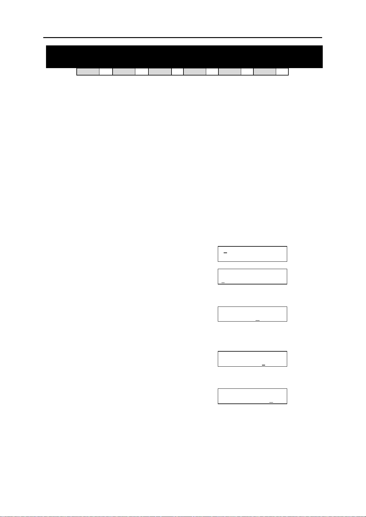
Allows the system administrator to program the call forward destinations for station users. Also
allows call forwarding to be set after the destination has been entered.
The system allows five types of call forwarding: FORWARD ALL, FORWARD BUSY, FORWARD
NO ANSWER, and FORWARD EXTERNAL. The FORWARD BUSY/NO ANSWER option allows
both BUSY and NO ANSWER options to be activated at the same time, provided that destinations have already been entered for both.
0 = FORWARD CANCEL 3 = NO ANSWER
1 = ALL CALL 4 = BUSY/NO ANSWER
2 = BUSY 5 = EXT (External)
PROGRAM KEYS
UP & DOWN Used to scroll through options
KEYPAD Used to enter selections
SOFT KEYS Move cursor left and right
SPEAKER Used to store data and advance to next MMC
HOLD Used to clear previous entry
ACTION DISPLAY
1. Open programming and select 102
Display shows
2. Dial station number (e.g., 205)
OR
Press UP or DOWN to select station and press
RIGHT soft key to move cursor
3. Dial 0–5 to select forward type
OR
Press UP or DOWN to select forward type and
press
RIGHT soft key to move cursor
4. Dial destination number (e.g., 201)
OR
Press UP or DOWN to select destination and
press RIGHT soft key to move cursor
5. Dial 1 for YES, 0 for NO
OR
Press UP or DOWN to select YES or NO
and press RIGHT soft key to return to step 2
6. Press TRSF to store and exit
OR
Press SPEAKER to store and advance
to next MMC
01] FORWARD
[2
0:FORWARD CANCEL
[205] FORWARD
:FORWARD CANCEL
0
[205] FORWARD
1:ALL CALL: N
[205] FORWARD
1:ALL CALL:201
[205] FORWARD
CURENTLY SET :Y
ONE
ES
MMC 102 (Page 1 of 2)
Page 44

DCS MMC PROGRAMS
COMBINED PROGRAMMING MANUAL NOVEMBER 2001
Default Data: All stations 0 (Forward Cancel)
Related Items: MMC 301 Assign Station COS
MMC 501 System -Wide Timers
MMC 502 Station-Wide Timers
MMC 701 Assign COS Contents
MMC 722 Station Key Programming
MMC 723 System Key Programming
MMC 102 (Page 2 of 2)
Page 45
DCS MMC PROGRAMS
COMBINED PROGRAMMING MANUAL NOVEMBER 2001
MMC: 103 SET ANSWER MODE
DCS
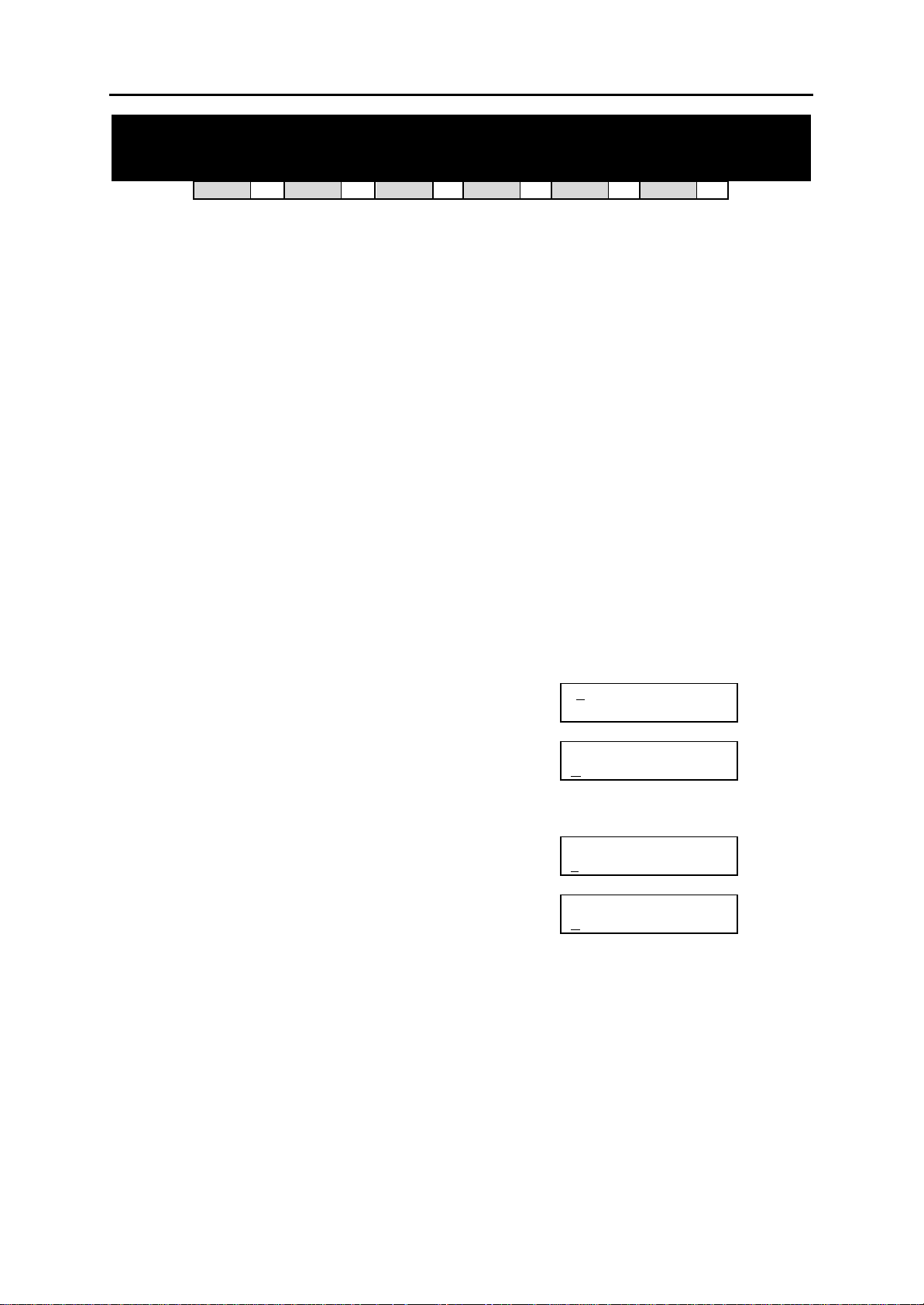
Allows the system administrator to change the answer mode of any keyset. Each keyset can
have its answer mode set to one of the following options:
0. RING: The keyset will ring in one of eight custom ring patterns. Calls are answered by pres sing
the ANS/RLS key or by lift ing the handset.
1. AUTO ANSWER: After giving a short attention tone, the keyset will automatically answer calls
on the speakerphone. When a C.O. line is transferred to a keyset in Auto Answer mode, the
screened portion of the call will be Auto Answer, but the keyset will ring when the transfer is
complete if the user has not pressed the ANS/RLS key or lifted the handset.
2. VOICE ANNOUNCE: The keyset will not ring. After a short attention tone, callers can make an
announcement but the ANS/RLS key or handset must be used to answer calls.
PROGRAM KEYS
UP & DOWN Used to scroll through options
KEYPAD Used to enter selections
SOFT KEYS Move cursor left and right
SPEAKER Used to store data and advance to next MMC
HOLD Used to clear previous entry
ANS/RLS Used to select ALL
ACTION DISPLAY
1. Open programming and select 103
Display shows
2. Dial keyset number (e.g., 205)
OR
Press UP or DOWN to select keyset
and press RIGHT soft key to move cursor
OR
Press ANS/RLS to select All [ALL] ANS MODE
3. Dial 0, 1 or 2 to change ring mode
OR
Press UP or DOWN to select ring mode and
press RIGHT soft key to return to step 2
4. Press TRSF to store and exit
OR
Press SPEAKER to store and advance to next MMC
Default Data: All keysets = RING
Ring frequency default = 5
Related Items: MMC 111 Keyset Ring Tone
33
CI
33
CII
33
816
33
408i
01] ANS MODE
[2
RING MODE
[205] ANS MODE
ING MODE
R
?
[205] ANS MODE
OICE ANNOUNCE
V
33
408
33
MMC 103 (Page 1 of 1)
Page 46
DCS MMC PROGRAMS
COMBINED PROGRAMMING MANUAL NOVEMBER 2001
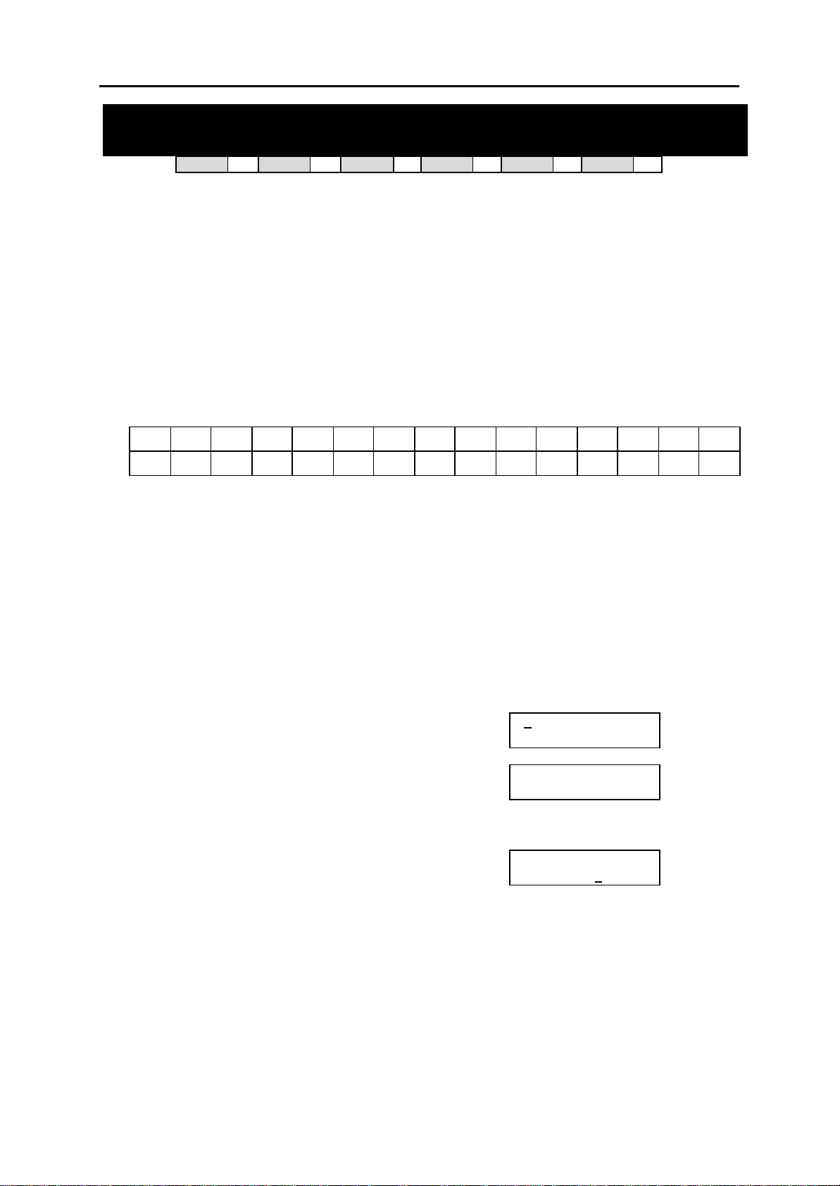
MMC: 104 STATION NAME
DCS
33
CI
33
CII
33
816
33
408i
33
408
33
Allows the system administrator to enter a name, up to 11 characters, to identify an individual st ation.
Names are written using the keypad. Each key press selects a character and moves the cursor to
the next position. For example, if the name is “SAM SMITH”, press the number “7” four times to
get the letter “S”. Now press the number “2” once to get the letter “A” Continue selecting characters from the keypad to complete your name. Press the programmable “A” key to toggle between
upper and lower case text.
Tip: When the character you want is on the same key as the previous character you typed in, press the UP
key to move the cursor to the right, then select the character.
The # key can be used for the following special characters (in sequence of key presses):
space
#
[ ] @ ^ ( ) _ + { } | ; "
PROGRAM KEYS
UP & DOWN Used to scroll through options
KEYPAD Used to enter selections
SOFT KEYS Move cursor left and right
SPEAKER Used to store data and advance to next MMC
HOLD Used to clear previous entry
“A” Key #19 (24B keyset) or key #7 (12B keyset) or key #1 (6B keyset)
ACTION DISPLAY
1. Open programming and select 104
Display shows
2. Dial station number (e.g., 205)
OR
Press UP or DOWN to select station and press
RIGHT soft key to move cursor
3. Enter the station name using the procedure described
above and press RIGHT soft key to return to step 2
4. Press TRSF to store and exit
OR
Press SPEAKER to store and advance to next MMC
Default Data: None
& ! : ? . , % $ - < > / =
→
toggles upper and lower case text.
01] STN NAME
[2
[205] STN NAME
_
[205] STN NAME
SAM SMITH _
`
Related Items: None
MMC 104 (Page 1 of 1)
Page 47
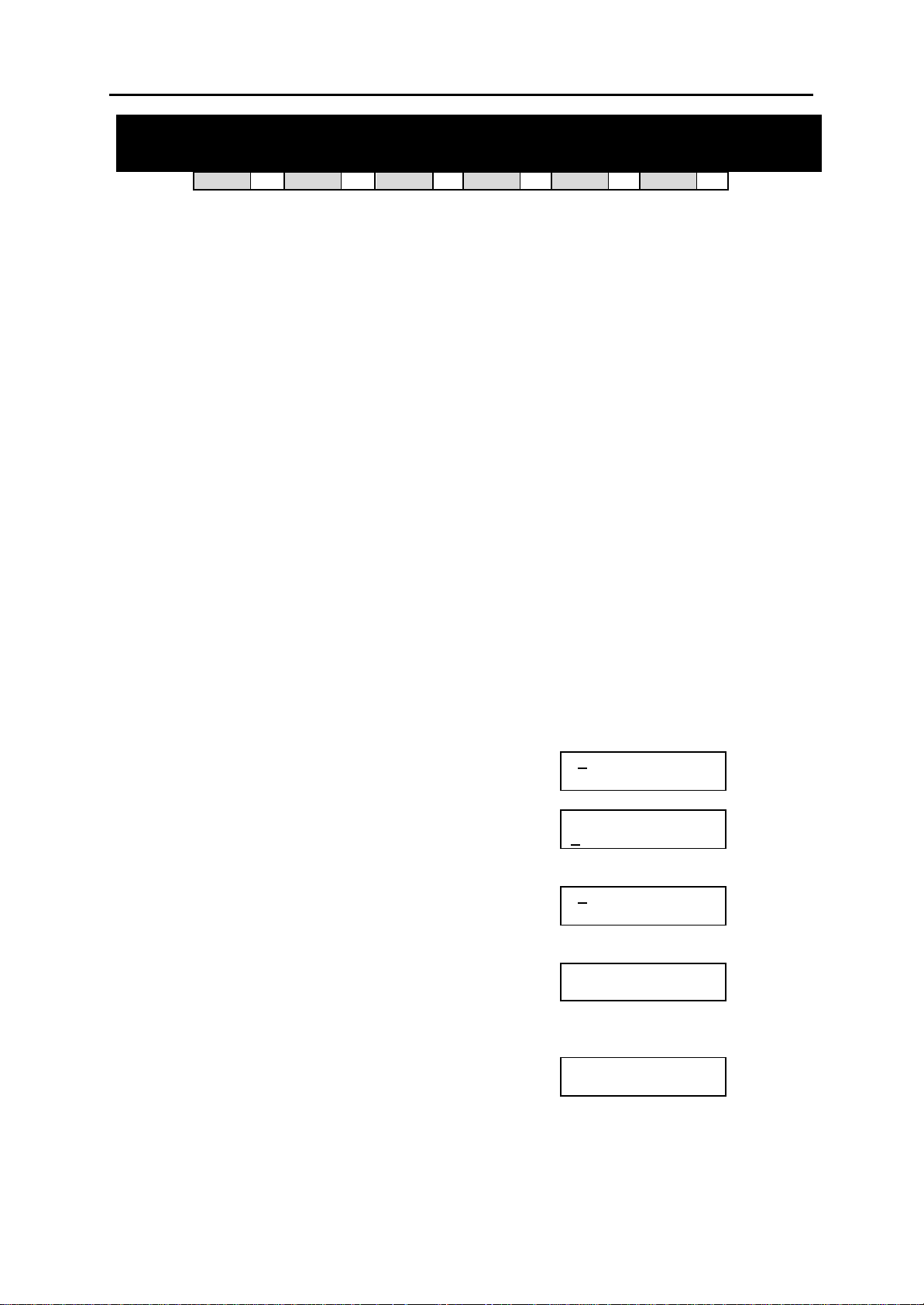
DCS MMC PROGRAMS
COMBINED PROGRAMMING MANUAL NOVEMBER 2001
MMC: 105 STATION SPEED DIAL
DCS
33
CI
33
CII
33
816
33
408i
33
408
33
Allows the system administrator to program personal speed dial numbers for stations. This may
be particularly useful for single line telephones which are more difficult to program by the station
user. Each station can have up to five blocks of speed dials—each containing 10 numbers (giving a total of 50 numbers) —assigned to it in MMC 606, Assign Speed Block. By default, each station has one block (for 10 numbers) assigned.
Speed dials are numbered 00–49. Each speed dial may contain a trunk or trunk group access
code (e.g. 9) fo llowed by a separator (–) and up to 24 digits to be dialled. These dialled digits
can be 0–9, [ and #. If the system recognises a valid trunk or trunk group access number, it will
automatically insert the separator.
PROGRAM KEYS
UP & DOWN Used to scroll through options
KEYPAD Used to enter selections
SOFT KEYS Move cursor left and right
SPEAKER Used to store data and advance to next MMC
HOLD Used to clear previous entry
“B” Used to insert a flash code “F”
”C” Used to insert a pause code “P”
”D” Used to insert a pulse/tone conversion code “C”
”E” Used to mask/unmask following digits (shows as “[“ or “]”)
”F” Used to enter name for speed dial bin (see MMC 106)
Keys “A” to “F” are keys #19 to #24 on 24B keysets, or keys #7 to #12 on 12B keysets, or keys
#1 to #6 on 6B keysets.
ACTION DISPLAY
1. Open programming and select 105
Display shows
2. Dial station number (e.g. 205)
OR
Press UP or DOWN to select station and press RIGHT
soft key to move cursor
If selected station has no speed dial blocks assigned,
the display will be as shown and a new station may be
selected.
3. Enter speed dial number (e.g., 05)
OR
Press UP or DOWN to select location and press RIGHT
soft key to move cursor
4. Enter trunk access code (e.g., 9) followed by the
number to be dialled (e.g., 08104264100)
If you make an error, press the HOLD key to clear an
entire entry or use the DOWN key to move the cursor
back
01] SPEED DIAL
[ 2
00 :
[205] SPEED DIAL
0 :
0
[ 205] SPEED DIAL
NO SPEED BLOCK
[205] SPEED DIAL
05: _
[205] SPEED DIAL
05 : 9-08104264100_
MMC 105 (Page 1 of 2)
Page 48

DCS MMC PROGRAMS
COMBINED PROGRAMMING MANUAL NOVEMBER 2001
5. Press the “F” key to access MMC 106, Station Speed
Dial Name, to enter name
OR
Press the LEFT soft key to return to step 3 (new dial no)
OR
Press the RIGHT soft key to return to step 2 (new stn)
OR
Press TRSF to save and exit
OR
Press SPEAKER to save and advance to next MMC
Default Data: None
Related Items: MMC 106 Station Speed Dial Name
MMC 606 Assign Speed Block
MMC 105 (Page 2 of 2)
Page 49
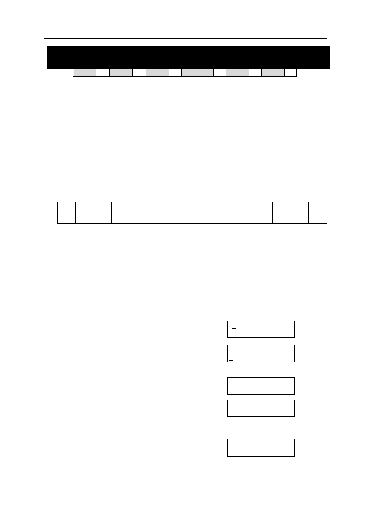
DCS MMC PROGRAMS
COMBINED PROGRAMMING MANUAL NOVEMBER 2001
MMC: 106
DCS
Allows a name, up to 11 characters, to be entered for each personal speed dial location. This
name enables the speed dial number to be located when the directory dial feature is used. The
directory dial feature allows the display keyset user to select a speed dial location by viewing its
name.
Names are written using the keypad. Each key press selects a character and moves the cursor to
the next position. For example, if the name is “SAM SMITH”, press the number “7” four times to
get the letter “S”. Now press the number “2” once to get the letter “A” Continue selecting characters from the keypad to complete your name. Press the programmable “A” key to toggle between
upper and lower case text.
Tip: When the character you want is on the same key as the previous character you typed in, press the UP
key to move the cursor to the right, then select the character.
The # key can be used for the following special characters (in sequence of key presses):
space
#
[ ] @ ^ ( ) _ + { } | ; "
PROGRAM KEYS
UP & DOWN Used to scroll through options
KEYPAD Used to enter selections
SOFT KEYS Move cursor left and right
SPEAKER Used to store data and advance to next MMC
HOLD Used to clear previous entry
“A” Key #19 (24B keyset) or key #7 (12B keyset) or key #1 (6B keyset)
ACTION DISPLAY
1. Open programming and select 106
Display shows
2. Dial station number (e.g., 205)
OR
Press UP or DOWN to select station and press
RIGHT soft key to move cursor
If selected station has no speed dial bins, the display
will be as shown and a new station may be selected
3. Dial speed dial location (e.g., 01)
OR
Press UP or DOWN to scroll through location
numbers and press RIGHT soft key to move cursor
4. Enter the location name using the procedure
described above and press RIGHT soft key to
return to step 2
33
CI
& ! : ? . , % $ - < > / =
STATION SPEED DIAL NAME
33
CII
toggles upper and lower case text.
33
816
33
408i
[ 2
00:
[205] SPEED NAME
00:
[ 2
NO SPEED BLOCK
[205] SPEED NAME
01:_
[205] SPEED NAME
01:SAM SMITH_
33
01] SPEED NAME
05] SPEED NAME
408
33
→
`
MMC 106 (Page 1 of 2)
Page 50

DCS MMC PROGRAMS
COMBINED PROGRAMMING MANUAL NOVEMBER 2001
5. Press TRSF to store and exit
OR
Press SPEAKER to store and advance to next MMC
Default Data: None
Related Items: MMC 105 Station Speed Dial
MMC 606 Assign Speed Block
MMC 106 (Page 2 of 2)
Page 51
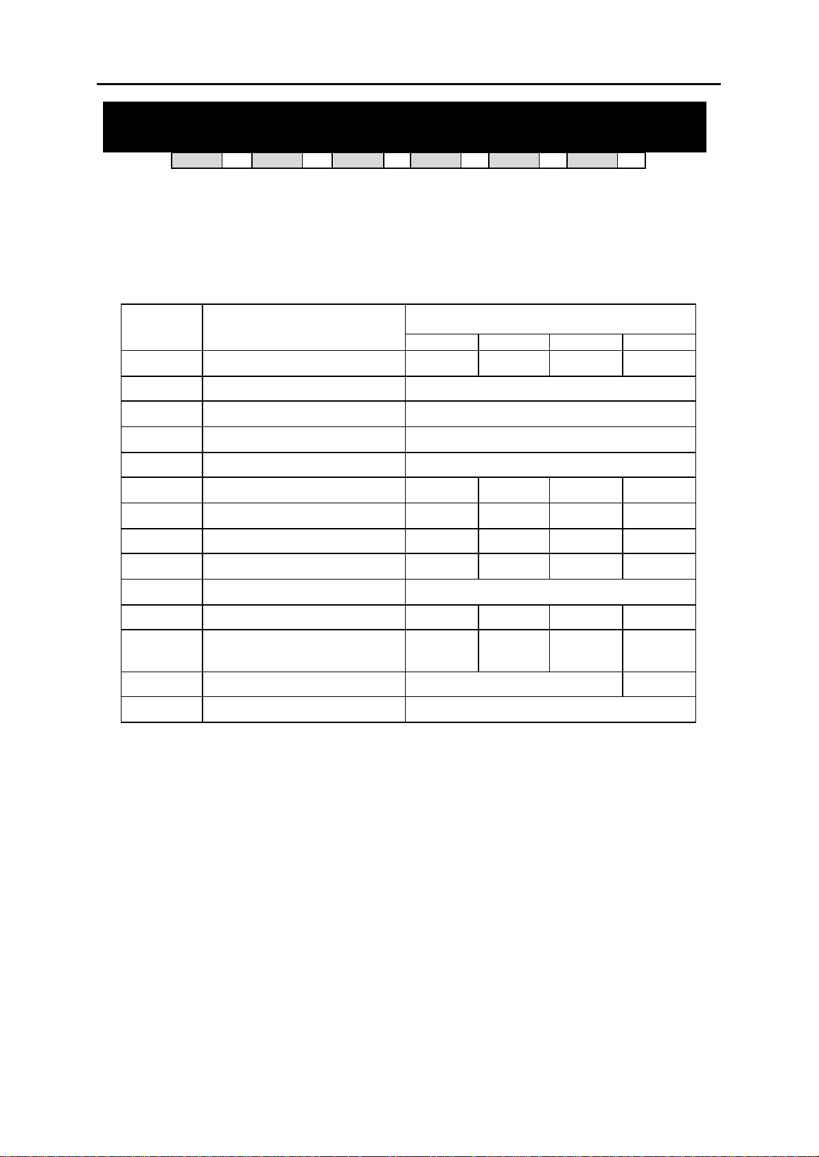
DCS MMC PROGRAMS
COMBINED PROGRAMMING MANUAL NOVEMBER 2001
MMC: 107 KEY EXTENDER
DCS
33
CI
33
CII
33
816
33
408i
33
408
33
Used to view the programmable keys assigned to keyset stations. In addition, it allows the
system administrator to assign key extenders to those programmed keys which can have extenders, making general access feature keys more specific. For example, you may want to
set an SPD (Speed Dial) key to dial personal speed dial code 01 when selected. (Extenders
may also be entered in MMC 722 or 723 when programming key assignments.) The feature
keys that can have extenders are listed below.
FEATURE
KEY
BOSS Boss and Secretary 1–4 1–4 1–4 1–2
DIR Directory dial by name type 1–3
DP Direct Pick Up Extension or station group number
DS Direct Station Select Station nu mber
FWRD Call Forward 0–5
GPIK Group Pick Up 01–20 01–20 01–08 01–04
IG In/Out Group 500–529 500–519 500–509 50–53
MMPG Meet Me Page 0–9, Q 0–9, Q 0–4, 5, Q 0–2, 5, Q
FUNCTION
EXTENDER
DCS CII 816 408/408i
PAGE Page 0–9, Q 0–9, Q 0–4, 5, Q 0–2, 5, Q
PMSG Programmed Station Message 01–20
SG Station Group 500–529 500–519 500–509 50–53
SPD Speed Dial 00–49,
500–999
SP UCD Supervisor UCD/ACD Group Nu mber N/A
VT VM Transfer VM/AA Group Number
PROGRAM KEYS
UP & DOWN Used to scroll through options
KEYPAD Used to enter selections
SOFT KEYS Move cursor left and right
SPEAKER Used to store data and advance to next MMC
HOLD Used to clear previous entry
00–49,
500–999
00–49,
500–799
00–49,
500–699
MMC 107 (Page 1 of 2)
Page 52
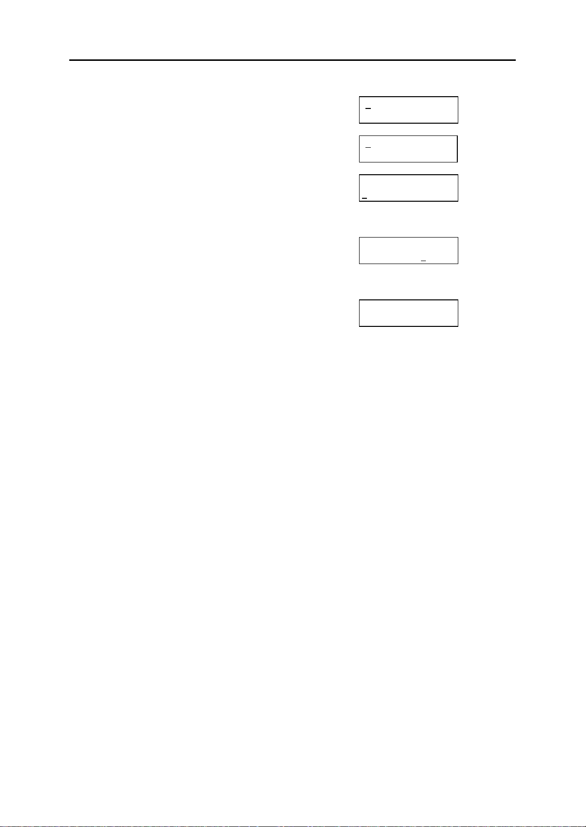
DCS MMC PROGRAMS
COMBINED PROGRAMMING MANUAL NOVEMBER 2001
ACTION DISPLAY
1. Open programming and select 107
Display shows
[201] EXT (MAST)
01:CALL1 →
OR OR
For 408 and 408i systems, display shows:
[21] EXT EXTEND
01:DT71 →
2. Dial station number (e.g., 205)
OR
Use UP or DOWN to scroll through station numbers
[205] EXT (MAST)
01:CALL1 →
and press RIGHT soft key to move the cursor
3. Enter key number (e.g., 18)
OR
Press UP and DOWN to scroll through keys and use
RIGHT soft key to move the cursor
OR
Use above table to select desired extender
System will return to this step
[205] EXT (MAST)
18:DS → _
205] EXT (MAST)
18:DS →DS207
4. Press TRSF to store and exit
OR
Press SPEAKER to store and advance to next MMC
Note: If the RIGHT soft key will not move the cursor to the right, you are attempting to add an extender to a key
that cannot have one (refer to the table, above, for allowed key extenders).
Default Data: None
Related Items: MMC 720 Copy Key Programming
MMC 721 Save Station Key Programming
MMC 722 Station Key Programming
MMC 723 System Key Programming
MMC 107 (Page 2 of 2)
Page 53
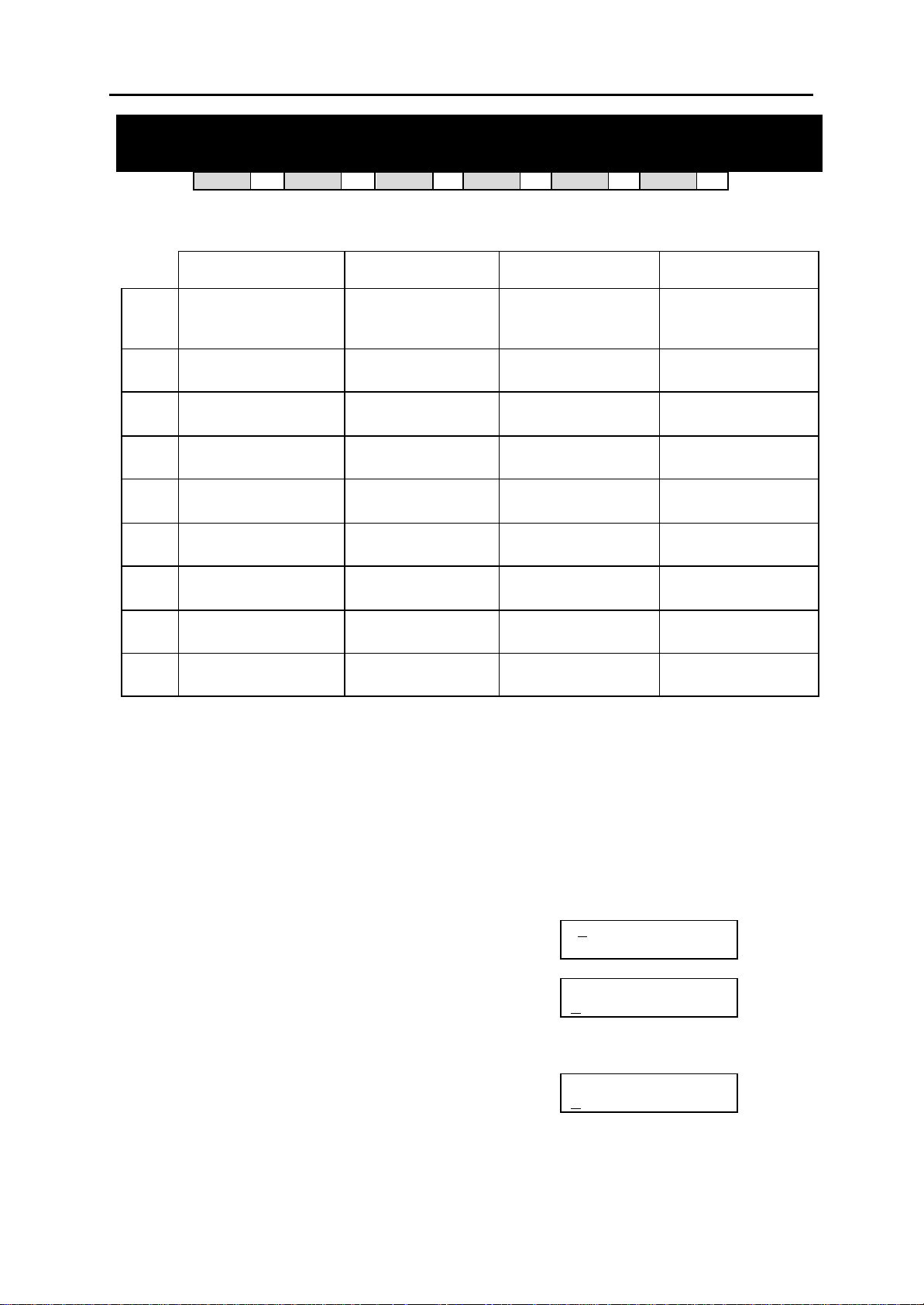
DCS MMC PROGRAMS
COMBINED PROGRAMMING MANUAL NOVEMBER 2001
MMC: 108 STATION STATUS
DCS
33
CI
33
CII
33
816
33
408i
This is a read-only MMC. Displays the following attributes of a station port:
0 PORT NO: #: Cabinet
(1–3)/Slot (1–7)/Port (1–
16)
1 TENANT NUMBER: 1–2 TYPE: Type of phone
2 TYPE: Type of phone
(e.g. 12B, 24B)
3 PICKUP GROUP: None,
01–20
4 SGR: Station Group
Number
5 BOSS-SECR: None,
BOSS, SECR
6 PAGE: Page Zone
(None, 1–4, *)
7 DAY COS NO: COS
(01–30)
DCS Compact II 816 408 / 408i
PORT NO: Slot
(BASE, OSLI, MISC,
EX1–7)/Port (1–16)
(e.g. 12B EU)
PICKUP GROUP:
None, 01–20
SGR: Stat ion Group
Number
BOSS-SECR: None,
BOSS, SECR
PAGE: Page Zone
(None, 1–4, *)
DAY COS NO: COS
(01–30)
NIGHT COS NO: COS
(01–30)
PORT NO: 8DLI (01–
08) or 4SLI (01–04)
TYPE: Type of phone
(e.g. 12B EU)
PICKUP GROUP:
None, 01–08
SGR: Station Group
Number
BOSS-SECR: None,
BOSS, SECR
PAGE: Page Zone
(None, 1–4, *)
DAY COS NO: COS
(01–10)
NIGHT COS NO: COS
(01–10)
33
408
33
PORT NO: 4DLI (01–
04) or 4SLI (01–04)
TYPE: Type of phone
(e.g. 12B EU)
PICKUP GROUP:
None, 01–04
SGR: Station Group
Number
BOSS-SECR: None,
BOSS, SECR
PAGE: Page Zone
(None, 1–2)
DAY COS NO: COS
(1–4)
NIGHT COS NO: COS
(1–4)
8 NIGHT COS NO: COS
(01–30)
— — —
PROGRAM KEYS
UP & DOWN Used to scroll through options
KEYPAD Used to enter selections
SOFT KEYS Move cursor left and right
SPEAKER Used to advance to next MMC
ACTION DISPLAY
1. Open programming and select 108
Display shows first station (e.g. for Compact II)
01] STN STATUS
[ 2
PORT NO:BASE01
2. Dial station number (e.g., 205)
OR
Press UP or DOWN to select station and press RIGHT
[205] STN STATUS
ORT NO:EX1-01
P
soft key to move cursor
3. Dial 0–8 using table above to select station status
option
[205] STN STATUS
ICKUP GROUP:01
P
OR
Press UP or DOWN to select status and press RIGHT
soft key to return to step 2
MMC 108 (Page 1 of 2)
Page 54

DCS MMC PROGRAMS
COMBINED PROGRAMMING MANUAL NOVEMBER 2001
4. Press TRSF to exit
OR
Press SPEAKER to advance to next MMC
Default Data: Port No: Follows hardware position
Type: Follows phone type
Tenant Number: 1 (DCS only)
Pickup Group: 01
SGR: None
Boss–Secr: None
Page: None
Day COS No: 01 (or 1)
Night COS No: 01 (or 1)
Related Items: MMC 301 Assign Station COS
MMC 302 Pickup Groups
MMC 303 Assign Boss/Secretary
MMC 601 Assign Station Group
MMC 604 Assign Station to Page Zone
MMC 803 Assign Tenant Group (DCS only)
MMC 108 (Page 2 of 2)
Page 55
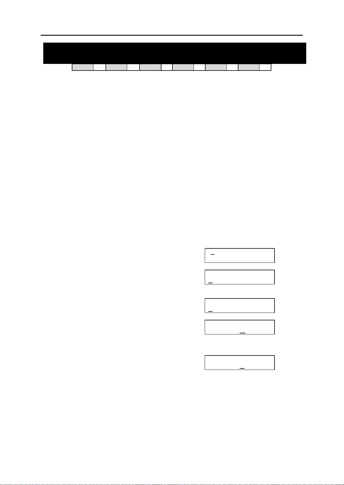
DCS MMC PROGRAMS
COMBINED PROGRAMMING MANUAL NOVEMBER 2001
MMC: 109 DATE DISPLAY
DCS
33
CI
33
CII
33
816
33
408i
33
408
33
Allows the system administrator to select the date and time display mode on a per-station basis
or system-wide.
0 COUNTRY Sets overall display format and has two options:
0 = ORIENTAL MM/DD DAY HH:MM
1 = WESTERN DAY DD MON HH:MM
1 CLOCK Sets format of clock display and has two options:
0 = 12 HOUR Displays 1
1 = 24 HOUR Displays 1
2 DISPLAY Sets format of DAY and MONTH display and has two options:
0 = UPPER CASE Displays Friday as FRI and March as MAR
1 = LOWER CASE Displays Friday as Fri and March as Mar
PROGRAM KEYS
UP & DOWN Used to scroll through options
KEYPAD Used to enter selections
SOFT KEYS Move cursor left and right
SPEAKER Used to store data and advance to next MMC
HOLD Used to clear previous entry
ANS/RLS Used to select ALL
ACTION DISPLAY
1. Open programming and select 109
Display shows
2. Dial station number (e.g., 205)
OR
Press UP or DOWN to select station and press
RIGHT soft key to move cursor
OR
Press ANS/RLS for all keysets
3. Dial 0–2 to select option (e.g. Country)
OR
Press UP or DOWN to scroll through modes and
press RIGHT soft key to move cursor
4. Dial 0 or 1 to select option format (e.g. Oriental)
OR
Press UP or DOWN to select format and
press RIGHT soft key to return to step 2
5. Press TRSF to store and exit
OR
Press SPEAKER to store and advance to next MMC
Default Data: Country: Western
Clock: 24 hour
Display: Lowercase
P.M. as 01:00
P.M. as 13:00
01] DAY FORMAT
[ 2
COUNTRY:WESTERN
[205] DAY FORMAT
OUNTRY:WESTERN
C
[ALL]DAY FORMAT
OUNTRY:?
C
[205] DAY FORMAT
COUNTRY:W
[205] DAY FORMAT
COUNTRY:O
ESTERN
RIENTAL
Related Items: MMC 505 Assign Date and Time
MMC 109 (Page 1 of 1)
Page 56

DCS MMC PROGRAMS
COMBINED PROGRAMMING MANUAL NOVEMBER 2001
MMC: 110 STATION ON/OFF
DCS
Allows the system administrator to set any of the following keyset features.
AUTO HOLD Automatically places an existing C.O. call on hold if a CALL key,
AUTO TIMER Automatically starts the stopwatch timer during a C.O. call. (CALL
HEADSET USE When ON, this feature disables the hookswitch allowing a headset
HOT KEYPAD When ON, this feature allows the user to dial numbers on the keypad
KEY TONE Allows the user to hear a slight tone when pressing keys on the key-
PAGE REJOIN Allows the user to hear the latter part of page announcements if the
RING PREFER When OFF, requires the user to press the fast flashing button to a n-
CALL COST If enabled (ON), LCD shows real-time call cost based on Metering
AME BGM Determines whether a station using Answering Machine Emulation
AME PSWD Sets the Answering Machine Emulation password ON or OFF. (Ca-
NOT CONT.CID When ON, the keyset displays the call timer for the duration of an in-
Note: Keyset users can set or change these options for their own keyset (refer to the Samsung DCS Keyset
User Guide for details).
PROGRAM KEYS
UP & DOWN Used to scroll through options
KEYPAD Used to enter selections
SOFT KEYS Move cursor left and right
SPEAKER Used to store data and advance to next MMC
HOLD Used to clear previous entry
ANS/RLS Used to select ALL
33
CI
33
CII
trunk key or trunk route key is pressed during that call.
COST option, below, should be OFF for this feature to work.)
user to answer all calls by pressing the ANS/RLS key.
without having to first lift the handset or press the SPEAKER key.
set.
keyset becomes free during a page.
swer a ringing call after lifting the handset.
Pulses arrived. (See AUTO TIMER option.)
will hear their personal greeting or background music (BGM) while
callers are listening to the personal greeting. A BGM source must be
selected for this to work. (Cadence and SVMi-4 voice mail systems
only.)
dence and SVMi-4 voice mail systems only.)
coming trunk call (if AUTO TI MER is ON). When OFF, the CLIP nu mber for a call is displayed for the dur ation of the call. (Not applicable
to 408 sy stems.)
33
816
33
408i
33
408
33
MMC 110 (Page 1 of 2)
Page 57

DCS MMC PROGRAMS
COMBINED PROGRAMMING MANUAL NOVEMBER 2001
ACTION DISPLAY
1. Open programming and select 110
Display shows
2. Dial station number (e.g., 205)
OR
Press UP or DOWN to select keyset and press
RIGHT soft key to move cursor
OR
Press ANS/RLS for ALL [ALL] STN ON/OFF
3. Press UP or DOWN to select option and
press RIGHT soft key to move cursor
4. Dial 1 for ON or 0 for OFF
OR
Press UP or DOWN to select ON or OFF and
press LEFT or RIGHT soft key to return to step 3
5. Press TRSF to store and exit
OR
Press SPEAKER to store and advance to next MMC
Default Data: Auto Hold Off
Auto Timer On
Headset Use Off
Hot Keypad On
Key Tone On
Page Rejoin On
Ring Pref On
Call Cost Off
Not Cont.CID Off
AME BGM Off
AME PSWD Off
Related Items: MMC 301 Assign Station COS
MMC 701 Assign COS Contents
01] STN ON/OFF
[ 2
AUTO HOLD :OFF
[205] STN ON/OFF
UTO HOLD :OFF
A
AUTO HOLD : ?
[205] STN ON/OFF
HOT KEYPAD : O
[205] STN ON/OFF
HOT KEYPAD :O
N
FF
MMC 110 (Page 2 of 2)
Page 58
DCS MMC PROGRAMS
COMBINED PROGRAMMING MANUAL NOVEMBER 2001
MMC: 111 KEYSET RING TONE
DCS
33
CI
33
CII
33
816
33
408i
33
408
33
Allows the system administrator to select the ring tone heard at each keyset. There are eight (1–
8) ring tones available. A short tone burst of the selection will be heard when a key is pressed.
PROGRAM KEYS
UP & DOWN Used to scroll through options
KEYPAD Used to enter selections
SOFT KEYS Move cursor left and right
SPEAKER Used to store data and advance to next MMC
HOLD Used to clear previous entry
ANS/RLS Used to select ALL
ACTION DISPLAY
1. Open programming and select 111
Display shows
2. Dial keyset number (e.g., 205)
OR
Press UP or DOWN to select station and press
RIGHT soft key to move cursor
OR
Press ANS/RLS to select All
3. Dial 1–8 to select ring tone
OR
Press UP or DOWN to select ring tone and press
RIGHT soft key to move cursor
4. Press TRSF to store and exit
OR
Press SPEAKER to store and advance to next MMC
Default Data: SELECTION 5
Related Items: MMC 114 Station Volume
01] RING TONE
[ 2
SELECTION 5
[205] RING TONE
SELECTION 5
[ALL] RING TONE
SELECTION ?
[205] RING TONE
SELECTION 6
MMC 111 (Page 1 of 1)
Page 59
DCS MMC PROGRAMS
COMBINED PROGRAMMING MANUAL NOVEMBER 2001
MMC: 112 ALARM REMINDER
DCS
33
CI
33
CII
33
816
33
408i
33
408
33
Allows the system administrator to set or change the alarm clock/appointment reminder feature
for any station. Keyset users can set their own alarms. A number of alarms may be set for each
station: three (1–3) for DCS systems or two (1– 2) for Compact II, 816 and 408/408i systems.
Each alarm may be defined as a one-time or TODAY alarm, or as a DAILY alarm, or NOTSET as
described below. The TODAY alarm is automatically cancelled after it rings, while the DAILY
alarm rings every day at the same time.
Dial 0: NOTSET Dial 1: TODAY Dial 2: DAILY
PROGRAM KEYS
UP & DOWN Used to scroll through options
KEYPAD Used to enter selections
SOFT KEYS Move cursor left and right
SPEAKER Used to store data and advance to next MMC
HOLD Used to clear previous entry
ACTION DISPLAY
1. Open programming and select 112
Display shows
2. Dial station number (e.g., 205)
OR
Press UP or DOWN to select station and
press RIGHT soft key to move cursor
3. Dial alarm number (e.g., 2)
OR
Press UP or DOWN to select alarm and
press RIGHT soft key to move cursor
OR
Press LEFT soft key to return to step 2
4. Enter alarm time in 24-hour clock format
(e.g., 1300)
Display will automatically advance to step 5
5. Dial valid entry from above list for alarm type (e.g. 2,
DAILY)
OR
Press UP or DOWN to select alarm type
and press RIGHT soft key to move cursor and
return to step 2
6. Press TRSF to store and exit
OR
Press SPEAKER to store and advance to next MMC
Default Data: Alarms set to NOTSET
Related Items: None
01] ALM CLK(1)
[2
HHMM: èNOTSET
[205] ALM CLK(1)
HHMM: èNOTSET
[205] ALM CLK(2
HHMM: èNOTSET
[205] ALM CLK (2)
HHMM:1300èN
[205] ALM CLK (2)
HHMM:1300èD
)
OTSET
AILY
MMC 112 (Page 1 of 1)
Page 60
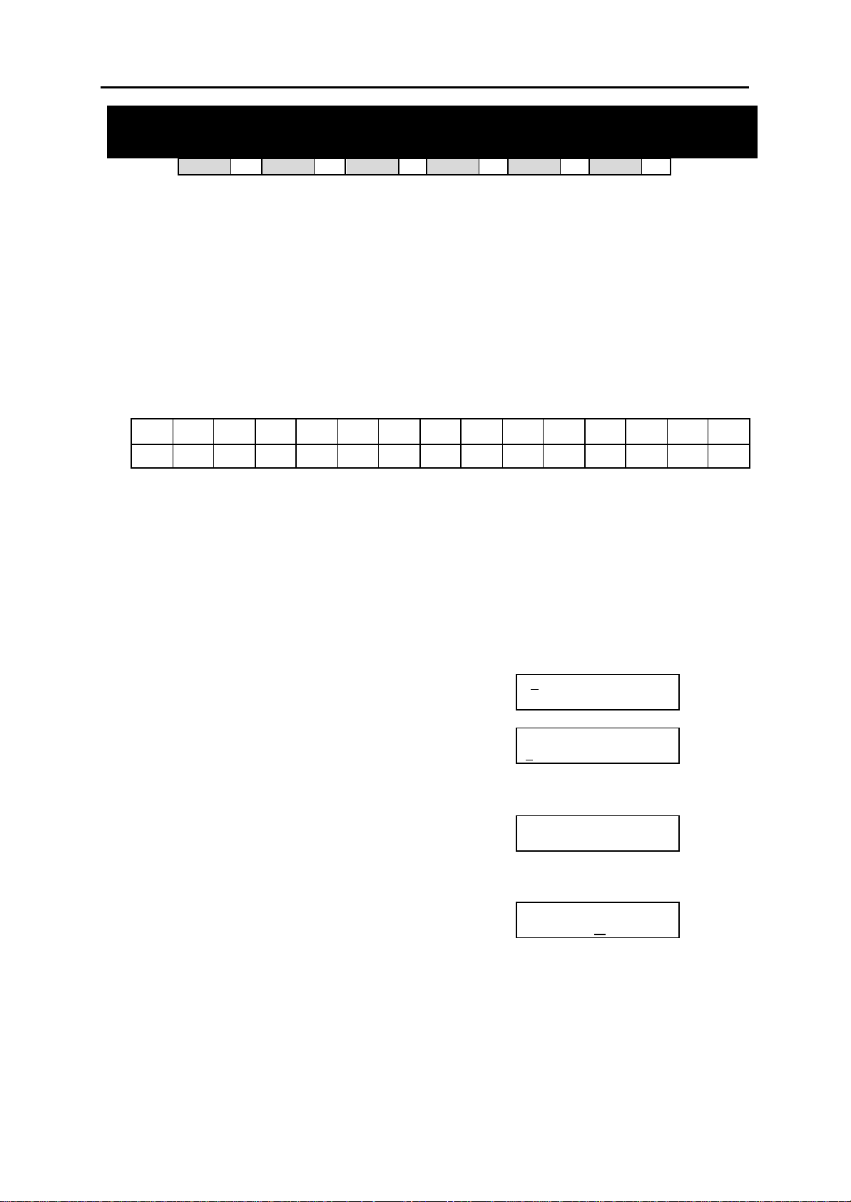
DCS MMC PROGRAMS
COMBINED PROGRAMMING MANUAL NOVEMBER 2001
MMC: 113 VIEW MEMO NUMBER
DCS
Allows the system administrator to enter memos on stations. Up to three memos can be entered,
depending on your system. MMC 116 (Alarm and Message) can be programmed to remind the
station user to read the memo(s).
Each memo can be up to 13 characters long and is entered using the dial keypad. For example,
press “6” once to enter the letter ”M”, and press ”3” twice for an ”E”. Continue selecting characters from the keypad to complete the memo. Press the programmable ”A” key to toggle between
upper and lower case text.
Tip: When the character you want is on the same key as the previous character you typed in, press the UP
key to move the cursor to the right, then select the character.
The # key can be used for the following special characters (in sequence of key presses):
space
#
[ ] @ ^ ( ) _ + { } | ; "
PROGRAM KEYS
KEYPAD Used to enter selections
SOFT KEYS Move cursor left and right
SPEAKER Used to store data and advance to next MMC
HOLD Used to clear previous entry
“A” Key #19 (24B keyset) or key #7 (12B keyset) or key #1 (6B keyset)
ACTION DISPLAY
1. Open programming and select 113
Display shows
2. Dial the station number (e.g., 205)
OR
Press UP or DOWN to select station and
press RIGHT soft key to move cursor
3. Dial memo number (1–3)
OR
Press UP or DOWN to select and press RIGHT soft
key to move cursor
4. Press RIGHT soft key to move cursor and add
memo via dial keypad using above procedure
5. Press TRSF to store and exit
OR
Press SPEAKER to store and advance to next MMC
Default Data: None
33
CI
& ! : ? . , % $ - < > / =
33
CII
toggles uppercase and lowercase text.
33
816
33
408i
01] VIEW MEMO
[2
1:
[205] VIEW MEMO
:
1
[205] VIEW MEMO
1:_
[205] VIEW MEMO
1:CALL TOM
33
408
33
→
`
Related Items: MMC 116 Alarm and Message
MMC 113 (Page 1 of 1)
Page 61
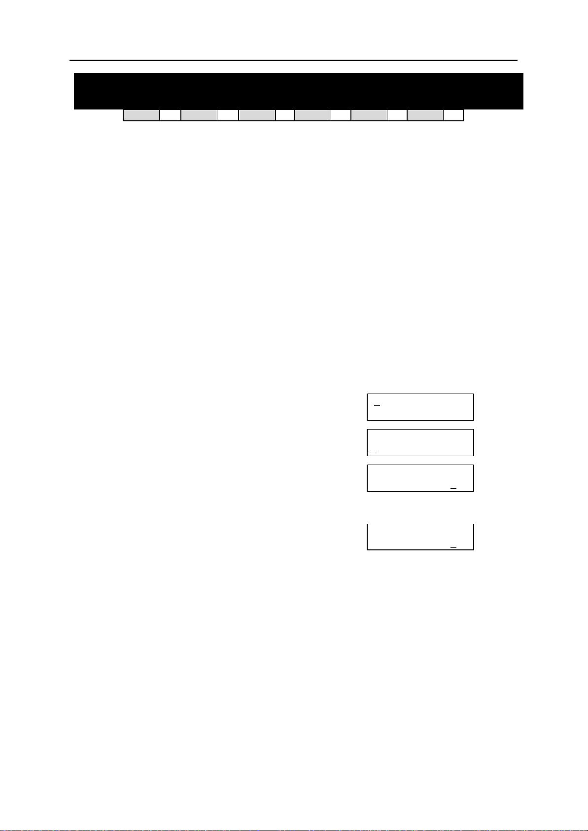
DCS MMC PROGRAMS
COMBINED PROGRAMMING MANUAL NOVEMBER 2001
MMC: 114 STATION VOLUME
DCS
Allows the system administrator to set volume levels for keysets.
0 RING VOLUME Set a level for ring volume. There are eight volume le vels: level 1 is
1 OFF-RING VOL Set a level for off -hook ring volume. There are eight vo lume levels:
2 HANDSET VOL Set a level for listening volume through handset. There are eight vol-
3 SPEAKER VOL Set a level for listening volume through speaker. There are 16 vo l-
4 BGM VOLUME Set a level for background music volume. There are 16 volume le v-
PROGRAM KEYS
UP & DOWN Used to scroll through options
KEYPAD Used to enter selections
SOFT KEYS Move cursor left and right
SPEAKER Used to store data and advance to next MMC
ANS/RLS Used to select ALL
ACTION DISPLAY
1. Open programming and select 114
Display shows
2. Dial station number (e.g. 205)
3. Dial option number
OR
Press UP or DOWN to select option and press
RIGHT soft key
4. Dial volume level using keypad (you will hear a brief tone
for the level you select) and system returns to step 3
OR
Press UP or DOWN to select volume (you will hear a brief
tone for each level) and press RIGHT soft key to return to
step 3
5. Press TRSF to store and exit
OR
Press SPEAKER to store and advance to next MMC
33
CI
33
CII
the lowest and level 8 the highest.
level 1 is the lowest and level 8 the highest.
ume levels: level 1 is the lowest and level 8 the highest.
ume levels: level 1 is the lowest and level 16 the highest.
els: level 1 is the lowest and level 16 the highest.
33
816
33
408i
33
408
[ 2
01] STN VOLUME
RING VOLUME : 4
[205] STN VOLUME
R ING VOLUME : 4
[205] STN VOLUME
OFF-RING VOL: 4
[205] STN VOLUME
OFF-RING VOL: 3
33
Default Data: Ring Volume 4
Off-Hook Ring Volume 4
Handset Volume 4
Speaker Volume 13
BGM Volume 13
Related Items: MMC 111 Keyset Ring Tone
MMC 114 (Page 1 of 1)
Page 62
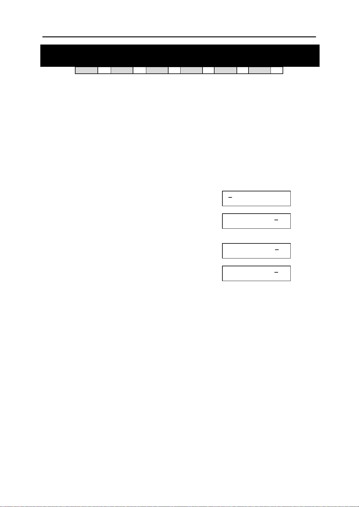
DCS MMC PROGRAMS
COMBINED PROGRAMMING MANUAL NOVEMBER 2001
MMC: 115
DCS
33
CI
SET PROGRAMMED MESSAGE
33
CII
33
816
33
408i
33
408
33
Allows the system administrator to set a programmed message at individual or all keysets. There
are 20 messages available (01–20). These messages are as set up in MMC 715, Programmed
Station Message.
PROGRAM KEYS
UP & DOWN Used to scroll through options
KEYPAD Used to enter selections
SOFT KEYS Move cursor left and right
SPEAKER Used to store data and advance to next MMC
HOLD Used to clear previous entry
ANS/RLS Used to select ALL
ACTION DISPLAY
1. Open programming and select 115
Display shows
2. Dial station number (e.g., 205)
OR
Press UP or DOWN to select station and press RIGHT
soft key to move cursor
OR
Press ANS/RLS to select All
3. Dial 01–20 to select message number (e.g., 05)
OR
Press UP or DOWN to select message and press RIGHT
soft key to return to step 2
OR
Select 00 to cancel a previously set message
4. Press TRSF to store and exit
OR
Press SPEAKER to store and advance to next MMC
Default Data: No messages selected
Related Items: MMC 715 Programmed Station Message
MMC 722 Station Key Programming
MMC 723 System Key Programming
01] PGMMSG(00)
[ 2
CANCEL PGM MSG
[205] PGMMSG(00)
CANCEL PGM MSG
[ALL] PGMMSG(? ?)
[205] PGMMSG(05)
PAGE ME
MMC 115 (Page 1 of 1)
Page 63

DCS MMC PROGRAMS
COMBINED PROGRAMMING MANUAL NOVEMBER 2001
MMC: 116 ALARM AND MESSAGE
DCS
33
CI
33
CII
33
816
33
408i
33
408
33
Allows the system administrator or technician to set or change the alarm clock/appointment reminder feature for individual or all stations. For DCS sy stems, three alarms (1–3) can be set
for each station. For other systems, two alarms (1–2) can be set. Each alarm may be defined
as a one-time or TODAY alarm, as a DAILY alarm, or NOTSET as described below. The TODAY
alarm is automatically cancelled a fter it rings, while the DAILY alarm rings every day at the same
time. It is also possible to set a message to display when the alarm is sounded.
Dial Alarm Type
0 NOTSET
1 TODAY
2 DAILY
Messages are written using the keypad. Each key press selects a character and moves the cursor to the next position. For example, if the message is “MEETING”, press the number “6” once
to get the letter “M”. Now press the number “3” twice to get the letter “E” Continue selecting
characters from the keypad to complete your message. Press the programmable “A” key to toggle between upper and lower case text.
Tip: When the character you want is on the same key as the previous character you typed in, press the UP
key to move the cursor to the right, then select the character.
The # key can be used for the following special characters (in sequence of key presses):
#
space
& ! : ? . , % $ - < > / =
[ ] @ ^ ( ) _ + { } | ; "
PROGRAM KEYS
UP & DOWN Used to scroll through options
KEYPAD Used to enter selections
SOFT KEYS Move cursor left and right
SPEAKER Used to store data and advance to next MMC
HOLD Used to clear previous entry
“A” Key #19 (24B keysets) or key #7 (12B keysets) or key #1 (6B key-
sets) toggles upper case and lower case text.
→
`
MMC 116 (Page 1 of 2)
Page 64

DCS MMC PROGRAMS
COMBINED PROGRAMMING MANUAL NOVEMBER 2001
ACTION DISPLAY
1. Open programming and select 116
Display shows
2. Dial station number (e.g., 205)
OR
Press UP or DOWN to select station and press RIGHT
soft key to move cursor
OR
Press ANS/RLS to select all stations
3. Dial alarm number (e.g., 2)
OR
Press UP or DOWN to select alarm and press RIGHT
soft key to move cursor
4. Enter alarm time in 24-hour clock format
(e.g., 1300 for 1pm)
Display will automatically advance to step 5
5. Dial valid entry from above list for alarm type (e.g. 2,
DAILY)
OR
Press UP or DOWN to select alarm type and press
RIGHT soft key to move cursor
6. Enter message using above method and press RIGHT
soft key to return to step 2
7. Press TRSF to store and exit
OR
Press SPEAKER to store and advance to next MMC
Default Data: Alarms set to NOTSET
Related Items: None
[ 201] ALM REM(1)
HHMM: è NOTSET
[205] ALM REM(1)
HHMM: è NOTSET
[ALL] ALM REM(1)
HHMM: è NOTSET
[205] ALM REM(2)
HHMM: è NOTSET
[205] ALM REM(2)
HHMM:1300èNOTSET
[205] ALM REM(2)
HHMM:1300èDAILY
[205] ALM REM(2)
Meeting
MMC 116 (Page 2 of 2)
Page 65
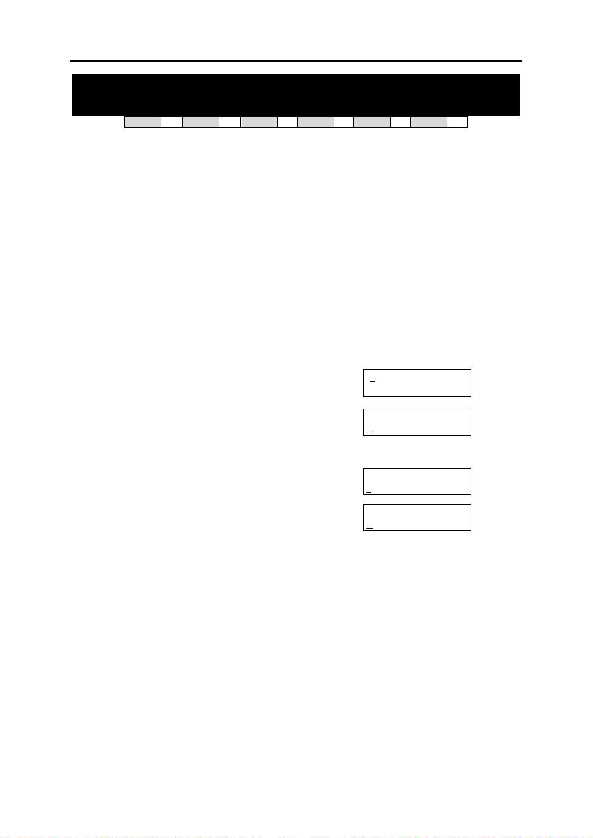
DCS MMC PROGRAMS
COMBINED PROGRAMMING MANUAL NOVEMBER 2001
MMC: 119 SET CLIP DISPLAY
DCS
33
CI
33
CII
33
816
33
408i
33
408
77
Allows the system administrator or keyset user to change the order in which CLIP information is
displayed on a keyset LCD. CLIP display options are as follows:
0 NO DISPLAY No CLIP data is displayed.
1 NUMBER FIRST CLIP number received from central office is displayed first.
2 NAME FIRST CLIP name is displayed first (if set in MMC 728)
PROGRAM KEYS
UP & DOWN Used to scroll through options
KEYPAD Used to enter selections
SPEAKER Save data and advance to next MMC
ANS/RLS Used to select ALL
ACTION DISPLAY
1. Open programming and select 119
Display shows
2. Enter station number (e.g. 204)
OR
Press UP or DOWN to scroll through stations and
press RIGHT soft key to select a station
OR
Press ANS/RLS to select ALL
3. Dial display option 0, 1 or 2 (e.g. 1)
Press UP or DOWN to select option and press
RIGHT or LEFT soft key to return to step 2
4. Press TRSF to store and exit
OR
Press SPEAKER to save and advance to next MMC
Default Data : NAME FIRST
Related Items: MMC 728 CLIP Translation Table
01] CLIP DISP.
[2
NAME FIRST
[204] CLIP DISP.
NAME FIRST
[ALL] CLIP DISP.
?
[204] CLIP DISP.
NUMBER FIRST
MMC 119 (Page 1 of 1)
Page 66
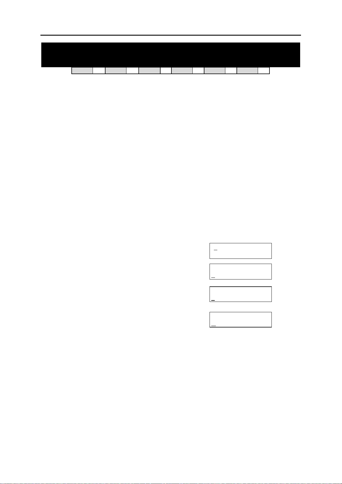
DCS MMC PROGRAMS
COMBINED PROGRAMMING MANUAL NOVEMBER 2001
MMC: 121 KEYSET LANGUAGE
DCS
Used to assign an LCD display based on a keyset user’s own language. Options include some or
all of the following, depending on your system:
ENGLISH
GERMAN
PORTUGAL
NORSK (NORWAY)
DANISH
DUTCH
ITALY
SPANISH
PROGRAM KEYS
UP & DOWN Used to scroll through options
KEYPAD Used to enter selections
SOFT KEYS Move cursor left and right
SPEAKER Used to store data and advance to next MMC
HOLD Used to clear previous entry
ANS/RLS Used to select ALL
ACTION DISPLAY
1. Open programming and select 121
Display shows
2. Dial keyset number (e.g., 205)
OR
Press UP or DOWN to select keyset and press RIGHT
soft key
OR
Press ANS/RLS to select All
3. Press UP or DOWN to select language and press
RIGHT soft key.
4. Press TRSF to store and exit
OR
Press SPEAKER to store and advance to next MMC
Default Data: ENGLISH
Related Items: Multi-Language
33
CI
77
CII
33
816
33
408i
[ 2
ENGLISH
[205] LANGUAGE
ENGLISH
[ALL] LANGUAGE
?
[205] LANGUAGE
GERMAN
33
408
01] LANGUAGE
33
MMC 121 (Page 1 of 1)
Page 67
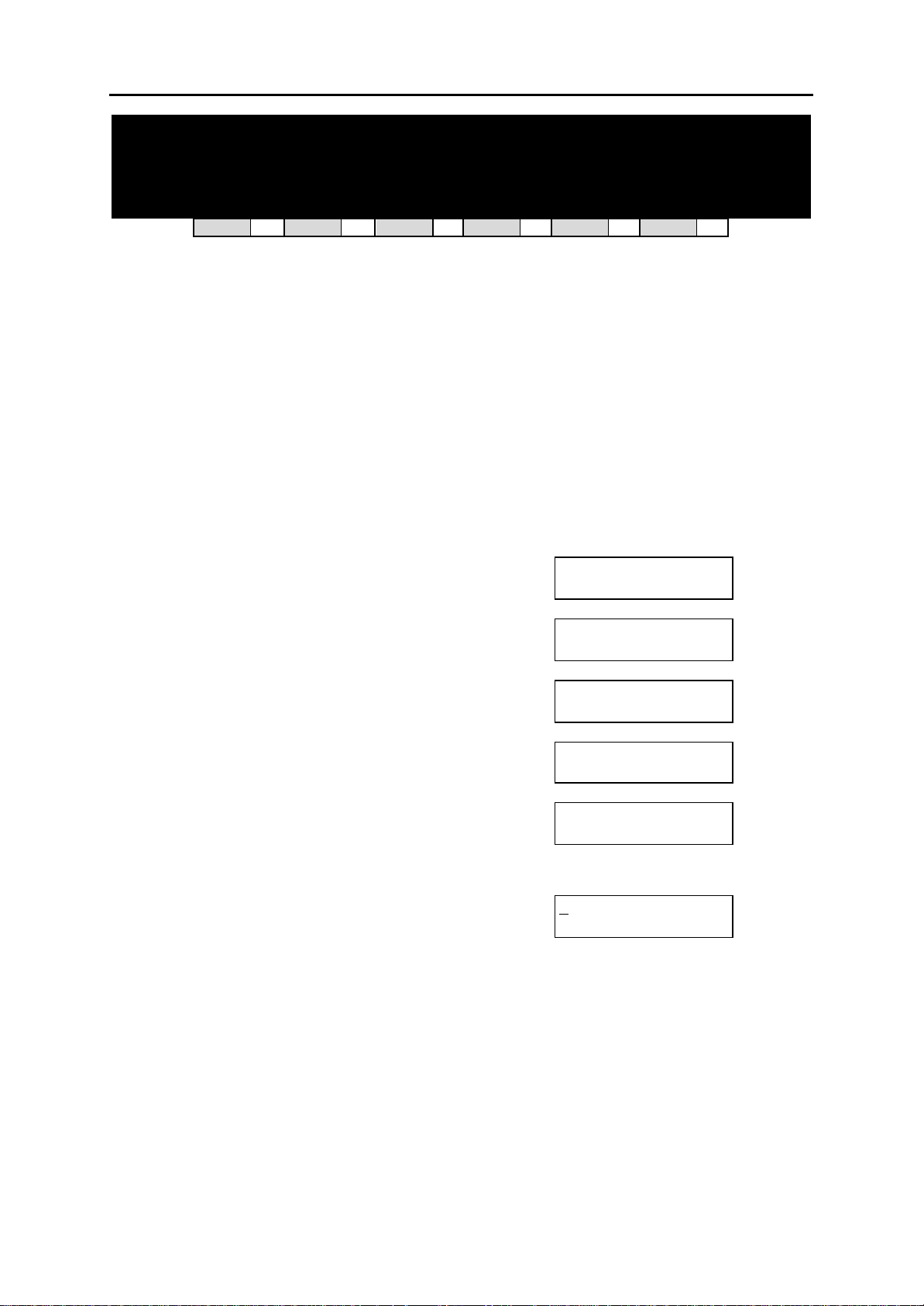
DCS MMC PROGRAMS
COMBINED PROGRAMMING MANUAL NOVEMBER 2001
MMC: 200 OPEN CUSTOMER PROGRAMMING
DCS
33
CI
33
CII
33
816
33
408i
33
408
33
Used to open (enable) or close (disable) customer-level programming by the system administrator. If programming is not opened and an attempt is made to access a customer -level MMC, the
error message [NOT PERMIT] will be displayed. A four-digit passcode is required to enable customer programming (which can be changed in MMC 201, if required). Each digit can be 0–9.
When opened, this MMC allows access to all MMCs specified by the system installer in MMC
802, Customer Access MMC Number.
PROGRAM KEYS
UP & DOWN Select open or closed
KEYPAD Used to enter passcode
SPEAKER Save data and advance to next MMC
TRSF Exit Programming
ACTION DISPLAY
1. Press TRSF 200
Display shows
2. Enter passcode
Correct code shows
Incorrect code shows
3. Dial 1 for ENABLE or 0 for DISABLE
OR
Press UP or DOWN arrow key to select ENABLE or
DISABLE and press RIGHT soft key
4. Press SPEAKER to advance to MMC entry level and
press UP or DOWN key to select MMC (e.g. 212)
OR
Enter MMC number and press RIGHT soft
key to enter MMC
5. Press TRSF key to exit
Default Data: DISABLE (closed)
Passcode=1234
Related Items: MMC 201 Change Customer Passcode
MMC 501 System -Wide Timers
MMC 802 Customer Access MMC Number
ENABLE CUS.PROG.
PASSCODE:_
ENABLE CUS.PROG.
PASSCODE: ∗∗∗∗
ENABLE CUS.PROG.
DISABLE
ENABLE CUS.PROG.
PASSWORD ERROR
ENABLE CUS.PROG.
ENABLE
12:ALARM RING
2
SELECT PROG. ID
MMC 200 (Page 1 of 1)
Page 68
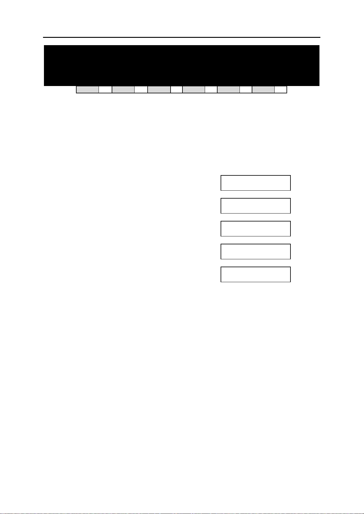
DCS MMC PROGRAMS
COMBINED PROGRAMMING MANUAL NOVEMBER 2001
MMC: 201 CHANGE CUSTOMER
PASSCODE
DCS
33
CI
33
CII
33
816
33
408i
33
408
33
Used to change the pas scode allowing access to MMC 200, Open Customer Programming , from
its current value.
PROGRAM KEYS
KEYPAD Used to enter passcodes
SPEAKER Save data and advance to next MMC
ACTION DISPLAY
1. Open programming and select 201
2. Enter new passcode via dial keypad (maximum four
digits)
3. Verify new passcode via dial keypad CUST. PASSCODE
PASSCODE verify successful
(go to step 4)
OR
PASSCODE verify failure
(return to step 2)
4. Press TRSF to store and exit
OR
Press SPEAKER to store and advance to
next MMC
Default Data: Passcode = 1234
Related Items: MMC 200 Open Customer Programming
CUST. PASSCODE
NEW CODE:_
CUST. PASSCODE
NEW CODE: QQQQ
VERIFY : QQQQ
CUST. PASSCODE
VERIFY :SUCCESS
CUST. PASSCODE
VERIFY :FAILURE
MMC 201 (Pages 1 of 1)
Page 69
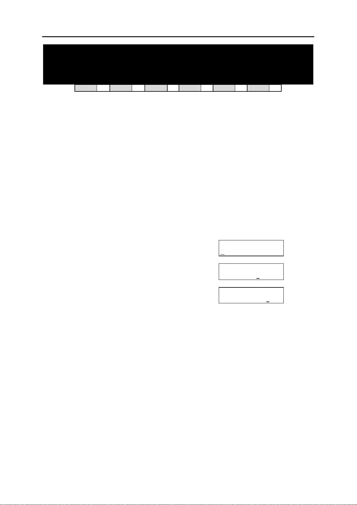
DCS MMC PROGRAMS
COMBINED PROGRAMMING MANUAL NOVEMBER 2001
MMC: 202 CHANGE FEATURE PASSCODES
DCS
33
CI
77
CII
33
816
33
408i
33
Your system supports some or all of the following features:
DAY/NIGHT
DISA ALARM
ALARM CLR
AA RECORD
DECT (BSI) REGISTER
This MMC is used to change the passcode for supported features
Note: The passcode is four digits long. Each digit can be 0–9.
PROGRAM KEYS
UP & DOWN Used to scroll through options
KEYPAD Used to enter passcodes
SPEAKER Save data and advance to next MMC
ACTION DISPLAY
1. Open programmi ng and select 202
Display shows
2. Press UP or DOWN key to make selection
Press RIGHT soft key to move cursor to passcode entry
3. Enter new passcode via digits from
dial keypad
Press RIGHT soft key to return to step 2
Continue to change other passcodes
4. Press TRSF to store and exit
OR
Press SPEAKER to store and advance to
next MMC
Default Data: DAY/NIGHT 0000
DISA ALARM 5678
ALARM CLR 8765
AA RECORD 4321
DECT REGISTER 4321
Related Items: MMC 212 Alarm Ringing Station
MMC 214 DISA Alarm Ringing Station
MMC 410 Assign DISA Trunk
MMC 507 Assign Auto Night Time
MMC 737 DECT System Code
MMC 744 BSI Registration On/Off
CHANGE PAS SCODE
DAY/NIGHT :0000
CHANGE PAS SCODE
ALARM CLR :8765
CHANGE PAS SCODE
ALARM CLR :9999
408
33
MMC 202 (Pages 1 of 1)
Page 70
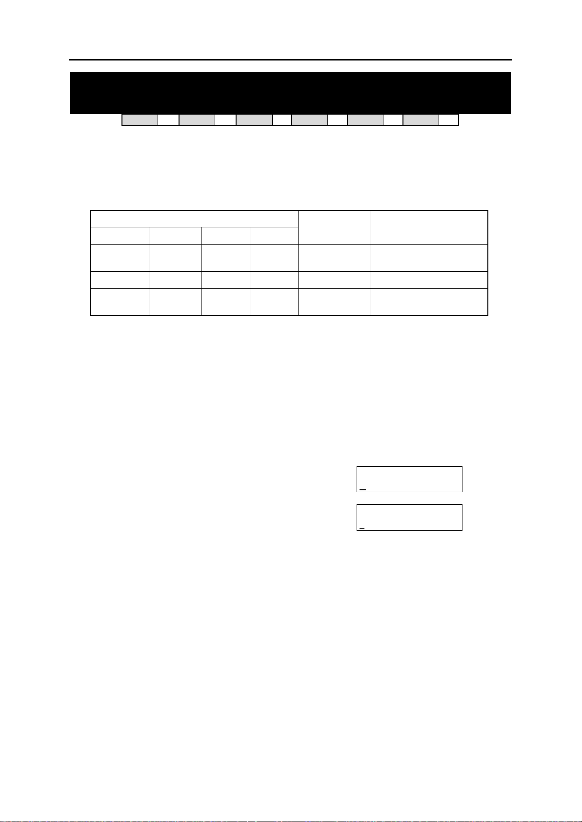
DCS MMC PROGRAMS
COMBINED PROGRAMMING MANUAL NOVEMBER 2001
MMC: 203 ASSIGN UA DEVICE
DCS
33
CI
33
CII
33
816
33
408i
33
408
33
Assigns the ringing device to be accessed when a Universal Answer (UA) key is pressed or the
UA pickup code is dialled. UA assignment is made in MMC 601, Assign Station Group, for a
group and then the group is entered here. The UA device can be one of the device types listed
below. The device type is automatically determined by the directory number (DN) entered.
DIRECTORY NUMBER (DN)
DCS CII 816 408/408i
201–349 201–308 201–216 21–28 STATION
3601–3602 361–365 361–362 361 RING PAGE Ring over page.
500–529 500–519 500–509 50–53
Note: Only one of the above options can be selected. If the ability to ring more than one item (e.g., all four
external page zones) is required, a station group containing all four zone codes must be created.
PROGRAM KEYS
UP & DOWN Used to scroll through options
KEYPAD Used to enter DN of selected device
SPEAKER Used to store data and advance to next MMC
HOLD Used to clear previous entry
ACTION DISPLAY
1. Open programming and select 203
Display shows current assignment
2. Dial DN of UA device (e.g., 205)
OR
Use UP and DOWN keys to scroll through
available devices
3. Press TRSF to store and exit
OR
Press SPEAKER to store and advance to next MMC
Default Data: None
Related Items: MMC 204 Common Bell Control
MMC 219 Common Relay Service Type
MMC 601 Assign Station Group
MMC 605 Assign External Page Zone
DEVICE TYPE DESCRIPTION
The UA device is a keyset
or SLT.
STATION
GROUP
The UA device is a station
group.
ASSIGN UA PORT
NONE-NO UA
ASSIGN UA PORT
205 -STATION
MMC 203 (Pages 1 of 1)
Page 71
DCS MMC PROGRAMS
COMBINED PROGRAMMING MANUAL NOVEMBER 2001
MMC: 204 COMMON BELL CONTROL
DCS
33
CI
33
CII
33
816
33
408i
33
408
33
Determines whether the common bell relay contacts have an interrupted or continuous clo sure
when activated. If interrupted is chosen, the relay follows an internal ring pattern of one second
closed followed by three seconds open.
By default, all common bell relay pairs are assigned as:
DCS: 380x
Compact II: 363–365
816: 362
408 an d 408i: 361
PROGRAM KEYS
UP & DOWN Used to scroll through options
KEYPAD Used to enter selections
SOFT KEYS Move cursor
SPEAKER Used to store data and advance to next MMC
ACTION DISPLAY
1. Open programming and select 204
Display shows current setting
(Note: Display differs according to system) OR
2. Dial common bell number
OR
Press UP or DOWN key to make selection of
common bell numbers and press RIGHT soft key to
advance cursor
3. Dial 0 for continuous or 1 for interrupted operation
OR
Use UP or DOWN to scroll through options
Press RIGHT soft key to return to step 2
4. Press TRSF to store and exit
OR
Press SPEAKER to store and advance to next MMC
Default Data: Continuous
Related Items: MMC 203 Assign UA Device
MMC 219 Common Relay Service Type
MMC 601 Assign Station Group
801]COM. BELL
[3
CONTINUOUS
[3
63] COM/LD BELL
CONTINUOUS
[3801]COM. BELL
INTERRUPTED
OR
[363] COM/LD BELL
INTERRUPTED
MMC 204 (Page 1 of 1)
Page 72

DCS MMC PROGRAMS
COMBINED PROGRAMMING MANUAL NOVEMBER 2001
MMC: 205 ASSIGN LOUD BELL
DCS
33
CI
77
CII
33
816
33
408i
33
408
33
Designates the station that controls the loud bell ring output of one of the following:
DCS systems—a Trunk A card. Each Trunk A card has one loud bell output; these outputs are
given a Directory Number of 3901–3920 as a default value to enable them to be assigned.
Compact II systems —a Misc card (assigned in MMC 219, Common Relay Service Type).
816 and 408/408i systems—a base board (assigned in MMC 219, Common Relay Service
Type).
The loud bell will follow the ring cadence of the designated station. Only a station can be assigned to control the loud bell; a station group cannot be assigned.
PROGRAM KEYS
UP & DOWN Used to scroll through options
KEYPAD Used to enter selections
SOFT KEYS Move cursor left and right
SPEAKER Used to store data and advance to next MMC
HOLD Clears previous entry
ACTION DISPLAY
1. Open programming and select 205
Display shows current setting
2. Dial loud bell number (e.g., 362)
OR
Use UP or DOWN to scroll through loud bell
numbers and press RIGHT soft key to move the cursor
3. Enter station number (e.g., 201)
OR
Press UP or DOWN key to make selection and
press RIGHT soft key to return to step 2
4. Press TRSF to store and exit
OR
Press SPEAKER to store and advance to next MMC
Default Data: NONE (Unassigned)
Related Items: MMC 219 Common Relay Service Type
61] LOUD BELL
[3
RING PAIR : NONE
[362] LOUD BELL
RING PAIR : NONE
[362] LOUD BELL
RING PAIR :201
MMC 205 (Page 1 of 1)
Page 73

DCS MMC PROGRAMS
COMBINED PROGRAMMING MANUAL NOVEMBER 2001
MMC: 206 BARGE-IN TYPE
DCS
33
CI
33
CII
33
816
33
408i
33
408
33
The Barge In feature allows selected keysets to intrude on other keysets which are not set as secure from barge in. This MMC sets the type of barge-in that is permitted.
DIAL TYPE OF BARGE-IN DESCRIPTION
0 NO BARGE IN Barge-in feature is unavailable regardless of a sta-
tion’s barge-in status.
1 WITH TONE Barge-in will have an intrusion tone and display at
the barged-in on station.
2 WITHOUT TONE There is no barge-in tone or display at the barged-in
on station and the barging-in station will be muted.
PROGRAM KEYS
UP & DOWN Used to scroll through options
KEYPAD Used to enter selections
SOFT KEYS Move cursor left and right
SPEAKER Used to store data and advance to next MMC
ACTION DISPLAY
1. Open programming and select 206
Display shows
2. Dial 0–2 to select barge-in type (e.g., 2)
OR
Press UP or DOWN to select barge-in type
and press RIGHT soft key
3. Press TRSF to store and exit
OR
Press SPEAKER to store and advance to next MMC
Default Data: NO BARGE IN
Related Items: MMC 301 Assign Station COS
MMC 701 Assign COS Contents
BARGE IN TYPE
NO BARGE IN
BARGE IN TYPE
WITHOUT TONE
MMC 206 (Page 1 of 1)
Page 74
DCS MMC PROGRAMS
COMBINED PROGRAMMING MANUAL NOVEMBER 2001
MMC: 207 ASSIGN VM/AA PORT
DCS
33
CI
33
CII
33
816
33
408i
33
408
33
Enables SLI ports to be designated as NORMAL or VMAA. VMAA ports receive digits desi gnated
in MMC 726, VM/AA Options, and also receive a true disconnect signal upon completion of a call.
Do not make VMAA ports data; this will return them to a single line port and stop voice mail int egration. VMAA ports have the equivalent of data protect written in the program and are protected
against tones.
PROGRAM KEYS
UP & DOWN Used to scroll through options
KEYPAD Used to enter selections
SOFT KEYS Move cursor left and right
SPEAKER Used to store data and advance to next MMC
HOLD Used to clear previous entry
ANS/RLS Used to select ALL
ACTION DISPLAY
1. Open programming and select 207
Display shows
2. Dial station number (e.g., 205)
OR
Press UP or DOWN to select station
and press RIGHT soft key to move cursor
3. Dial 1 or 0 to select port type (1=VMAA, 0=NORMAL)
OR
Press UP or DOWN to select option and press
RIGHT soft key
4. Press TRSF to store and exit
OR
Press SPEAKER to store and advance to next MMC
Default Data: NORMAL PORT
Related Items: MMC 601 Assign Station Group
MMC 726 VM/AA Options
09] VMAA PORT
[2
NORMAL PORT
[205] VMAA PORT
NORMAL PORT
[205] VMAA PORT
VMAA PORT
MMC 207 (Page 1 of 1)
Page 75
DCS MMC PROGRAMS
COMBINED PROGRAMMING MANUAL NOVEMBER 2001
MMC: 208 ASSIGN RING TYPE
DCS
33
CI
33
CII
33
816
33
408i
33
408
33
Provides the flexibility to program SLTs to have ICM ringing, C.O. ringing and data secure. With
the many types of external ringing devices, all configurations can be met. DATA RING also has a
positive disconnect signal. Do not make VM/AA ports data; this will return them to a single line
port and stop voice mail integration.
OPTIONS
0 ICM RING
1 C.O. RING
2 DATA RING
PROGRAM KEYS
UP & DOWN Used to scroll through options
KEYPAD Used to enter selections
SOFT KEYS Move cursor left and right
SPEAKER Used to store data and advance to next MMC
HOLD Used to clear previous entry
ANS/RLS Used to select ALL
ACTION DISPLAY
1. Open programming and select 208
Display shows
2. Dial SLT station number (e.g., 205)
OR
Press UP or DOWN to select station and
press RIGHT soft key to move cursor
3. Dial 0, 1 or 2 to select port type (e.g. 2)
OR
Press UP or DOWN to select option and press
LEFT or RIGHT soft key to return to step 2 above
4. Press TRSF to store and exit
OR
Press SPEAKER to store and advance to next MMC
Default Data: ICM RING
Related Items: None
09] RING TYPE
[2
ICM RING
[205] RING TYPE
ICM RING
[205] RING TYPE
DATA RING
MMC 208 (Page 1 of 1)
Page 76
DCS MMC PROGRAMS
COMBINED PROGRAMMING MANUAL NOVEMBER 2001
MMC: 209 ASSIGN ADD-ON MODULE
DCS
33
CI
33
CII
33
816
33
408i
77
Designates to which station an add-on module (AOM) is assigned.
PROGRAM KEYS
UP & DOWN Used to scroll through options
KEYPAD Used to enter selections
SOFT KEYS Move cursor left and right
RELEASE Used to store data and advance to next MMC
HOLD Clears previous entry
ACTION DISPLAY
1. Open programming and select 209
Display shows first AOM
2. Dial AOM number
OR
Press UP or DOWN to scroll through AOM numbers
and press RIGHT soft key to move the cursor
3. Enter station number, (e.g., 201)
OR
Press UP or DOWN to select station numbers
4. Press TRSF to store and exit
OR
Press SPEAKER to store and advance to next MMC
Default Data: MASTER = NONE
Related Items: None
01] AOM MASTER
[3
MASTER:NONE
[301] AOM MASTER
MASTER:NONE
[301] AOM MASTER
MASTER:201
408
77
MMC 209 (Page 1 of 1)
Page 77
DCS MMC PROGRAMS
COMBINED PROGRAMMING MANUAL NOVEMBER 2001
MMC: 210 CUSTOMER ON/OFF
DCS
33
CI
33
CII
33
816
33
408i
33
408
33
Allows the system administrator to set system features on or off. Not all features are available on
all systems. Refer to the following table for details (a tick means “available”).
FEATURE
DISA PSWD Determines whether outside customers are required to
LCR ENABLE Enables LCR feature in the system.
SMDI VMS SET Allows SMDI integration through RS-232 port for the ex-
PERI UCD SET Periodic UCD information provider. Enables UCD statis-
CID CODE INS Allows the digit ‘1’ to be automatically inserted for a toll
DISA MOH An additional option that can be presented to outside
DESCRIPTION
enter DISA passcode (Yes=ON, No=OFF).
ternal PC-based Voice Mail system
tics data on a per UCD group basis to print out on the I/O
port which has been set as SMDR or UCD REPT in real
time (see MMC 501- PERI UCD REPORT timer option).
This allows extended manipulation of the information by
an external third-party-provided software package.
call. (Not used in UK.)
DISA callers: a variable indication provided by an MOH
source instead of a fixed DISA dial tone.
DCS / C II 816 408/408i
SYSTEM
33 33 33
33 33 33
33
33 33
33 33
33 33 33
7 7
7
408i only
TRANSFER MOH Callers who have been transferred from an exte nsion or
UCD group or AA group will hear MOH, until answered
by the called extension, instead of ring back tone.
DSP SSPDNAME LCD displays programmed name of SYSTEM SPEED bin
(in MMC 706) if it has been programmed; if not, it shows
digits programmed in MMC 705 even if this is set to ON.
DID BSY ROUT DDI calls to a busy extension can be routed to an as-
signed destination, in MMC 406, before the call is
dropped.
DID NOT ROUT DDI calls with no mapping in MMC 714 can be routed to
an assigned destination in MMC 406.
ALL PICK UP Independent pickup group, can pick up all calls.
ARD TONE CHK When system dete cts CO BUSY TONE from Central Of-
fice, it returns to autoredial state.
VPN ENABLE Allows use of VPN (Virtual Private Network) feature linked
with network. (For future use.)
ISDNTRK BUSY Allows busy tone to be returned to incoming DDI calls to
station group if all group members are busy. (Sequential
or distribute groups only.)
IN TOLL CHK For future use.
ISDN PROGCON For future use.
ISDN KEYFAC ISDN Key Facility.
33 33 33
33 33 33
33 33
33 33
7
33 33 33
33 33
33
33 33 33
33 33
33 33
7 408i only
408i only
408i only
33 33
408 only
408i only
408i only
MMC 210 (Page 1 of 2)
Page 78

DCS MMC PROGRAMS
COMBINED PROGRAMMING MANUAL NOVEMBER 2001
PROGRAM KEYS
UP & DOWN Used to scroll through options
KEYPAD Used to enter selections
SOFT KEYS Move cursor left and right
SPEAKER Used to store data and advance to next MMC
ACTION DISPLAY
1. Open programming and select 210
Display shows
2. Dial option number (e.g. 01)
OR
Press UP or DOWN to select option
Press RIGHT soft key to move cursor
3. Dial 1 for ON or 0 for OFF
OR
Press UP or DOWN to make selection and press
RIGHT soft key
4. Repeat steps 2-3 for other options
OR
Press TRSF to store and exit
OR
Press SPEAKER to store and advance to next MMC
Default Data: DISA PSWD On
LCR ENABLE Off
SMDI VMS SET Off
PERI UCD SET Off
CID CODE INS Off
DISA MOH Off
TRANSFER MOH Off
DSP SSPDNAME Off
DID BSY ROUT Off
DID NOT ROUT On
ALL PICK UP Off
ARD TONE CHK On
VPN ENABLE Off
ISDNTRK BUSY Off
IN TOLL CHK Off
ISDN PROGCON Off
Related Items: None
TEN. ON AND OFF
DISA PSWD :ON
TEN. ON AND OFF
LCR ENABLE :OFF
TEN. ON AND OFF
LCR ENABLE :ON
MMC 210 (Page 2 of 2)
Page 79

DCS MMC PROGRAMS
COMBINED PROGRAMMING MANUAL NOVEMBER 2001
MMC: 211 DOOR RING ASSIGNMENT
DCS
Designates which devices will ring when a doorphone button is pressed for both day and night
mode. Two types of device can ring: station and station group; these are listed below with their
default directory numbers.
Station 201–349 201–308 201–216 21–28
Station group 500–529 500–519 500–509 50–53
PROGRAM KEYS
UP & DOWN Used to scroll through options
KEYPAD Used to enter selections
SOFT KEYS Move cursor left and right
SPEAKER Used to store data and advance to next MMC
HOLD Clears previous entry
ANS/RLS Used to select ALL
ACTION DISPLAY
1. Open programming and select 211
Display shows first doorphone
(If there is no doorphone interface module, you
see “DOOR NOT EXIST”)
2. Dial doorphone number (e.g., 210)
OR
Press UP or DOWN to scroll through
doorphone numbers and use the RIGHT
soft key to mo ve cursor
OR
Press ANS/RLS to select all door ring
3. Enter new DAY selection via dial keypad (e.g. 301)
OR
Press UP or DOWN key to make selection and
press RIGHT soft key
4. Enter new NIGHT selection via dial keypad (e.g. 302)
OR
Press UP or DOWN key to make selection and
press RIGHT soft key
5. Press RIGHT soft key to return to step 2
OR
Press LEFT soft key to return to step 3
OR
Press TRSF to store and exit
OR
Press SPEAKER to store and advance to next MMC
Default Data: Station group 500 for day and night (group 50 for 408/408i systems)
33
CI
33
CII
DCS Compact II 816 408/408i
33
816
DEFAULT DIRECTORY NUMBER DEVICE
33
408i
01] DOOR RING
[2
D:500 N:500
[210] DOOR RING
D:500 N:500
[ALL] DOOR RING
D:500 N:500
[210] DOOR RING
D:301 N: 500
[210] DOOR RING
D:301 N:302
33
408
33
Related Items: None
MMC 211 (Page 1 of 1)
Page 80
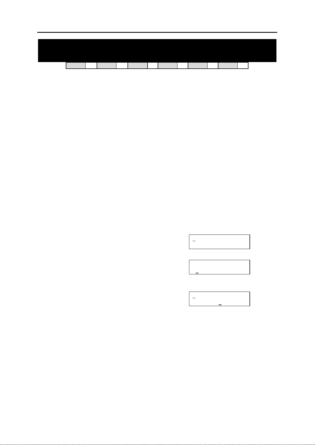
DCS MMC PROGRAMS
COMBINED PROGRAMMING MANUAL NOVEMBER 2001
MMC: 212 ALARM RINGING STATION
DCS
33
CI
77
CII
33
816
77
408i
77
408
77
Used to determine which devices will be alerted when an alarm sensor is activated.
Device DCS Compact II
Station 201–349 201 - 308
Station group 500–529 500 - 519
The above devices will ring like a doorphone and follow the door ring time-out. When ringing,
display keysets show the display assigned in MMC 213, Alarm Message. The bottom line of the
keyset display gives an option to clear the alarm. Ringing initiated by an alarm sensor is answered by going off-hook and on-hook again at a ringing keyset. If a device such as Ring Over
Page or a common bell is the only device assigned to ring, it may be answered by assigning a
direct pickup key with this device as the extender. If the alarm is unanswered by the door ring
time-out, ringing will cease but the display will remain until cleared by dialling the alarm clear feature code (57) and passcode (default 8765).
PROGRAM KEYS
UP & DOWN Used to scroll through options
KEYPAD Used to enter selections
SOFT KEYS Move cursor left and right
SPEAKER Used to store data and advance to next MMC
HOLD Used to clear previous entry
ACTION DISPLAY
1. Open programming and select 212
Display shows first sensor (3501 on DCS system or
351 on Compact II system)
2. Dial sensor number (e.g., 3502 or 352)
OR
Use UP or DOWN to scroll through sensor numbers
and press RIGHT soft key to advance cursor
3. Enter valid ring destination for day (e.g., 205)
OR
Press UP or DOWN key to make selection and press
RIGHT soft key to advance cursor
Select night destination in the same way
4. Press TRSF to store and exit
OR
Press SPEAKER to store and advance to next MMC
501]ALARM RING
[3
D:500 N:500
[3502]ALARM RING
D:500 N:500
502]ALARM RING
[3
D:205 N: 500
Default Data: All sensors ring 500 day/night
Related Items: MMC 213 Alarm Message
MMC 212 [DCS / Compact II] (Page 1 of 1)
Page 81
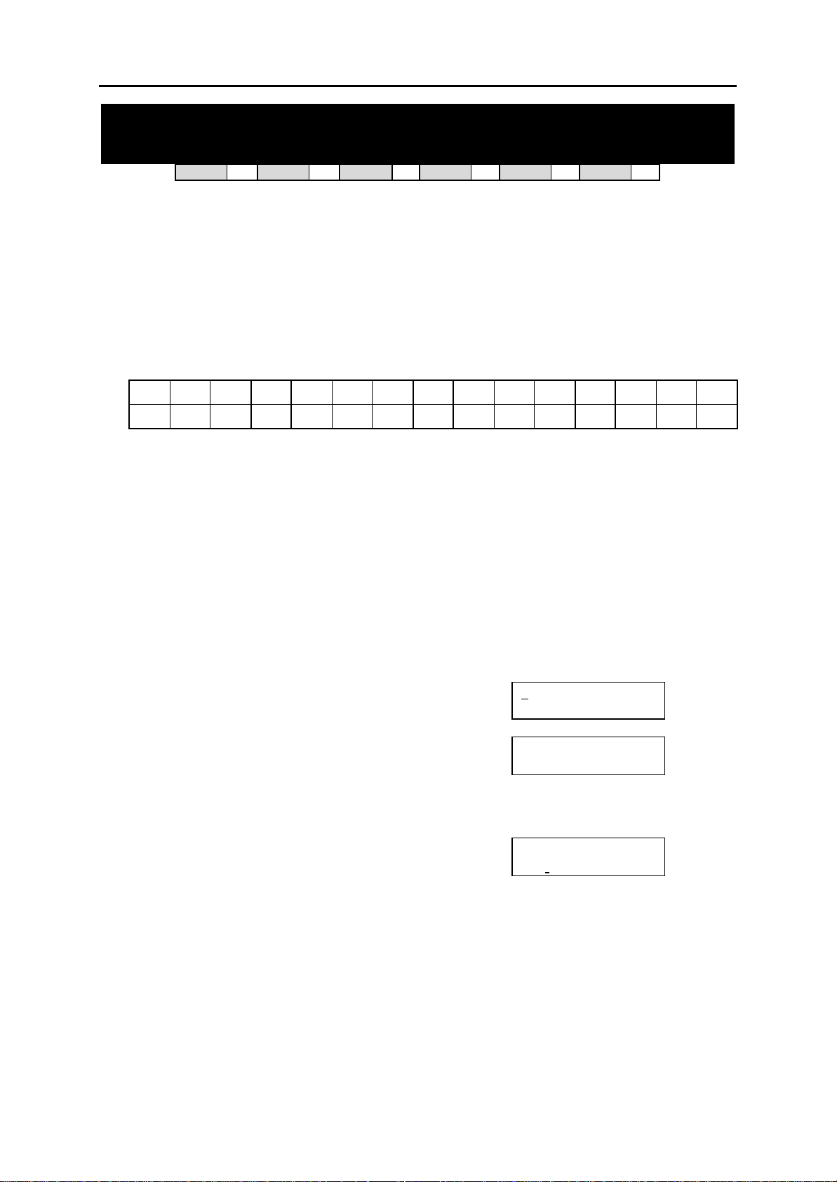
DCS MMC PROGRAMS
COMBINED PROGRAMMING MANUAL NOVEMBER 2001
MMC: 213 ALARM MESSAGE
DCS
Allows the assignment of a name to an alarm sensor. Names are written using the dial keypad.
Each press of a key selects a character and mo ves the cursor to the next position. For example,
if the sensor name is “FIRE,” press the number “3” three times to get the letter “F.” Now press
the number “4” three times to get the letter “I", and so on to complete the name. Press the programmable ”A” key to toggle between upper and lower case text.
Tip: When the character you want is on the same key as the previous character you typed in, press the UP
key to move the cursor to the right, then select the character.
The # key can be used for the followi ng special characters (in sequence of key presses):
space
#
[ ] @ ^ ( ) _ + { } | ; "
PROGRAM KEYS
UP & DOWN Used to scroll through options
KEYPAD Used to enter selections
SOFT KEYS Move cursor left and right
SPEAKER Used to store data and advance to next MMC
HOLD Used to clear previous entry
“A” Key #19 (24B keyset) or key #7 (12B keyset) or key #1 (6B keyset)
ACTION DISPLAY
Open programming and select 213
1.
Default Data: None
Related Items: MMC 212 Alarm Ringing Station
Display shows (e.g. 351 for Compact II)
2. Dial ALARM (e.g., 351 for Compact II or 3502
for DCS)
OR
Press UP or DOWN key to make selection
and press RIGHT soft key to move cursor
3. Enter name using method described above and
press RIGHT soft key to return to step 2
4. Press TRSF to store and exit
OR
Press SPEAKER to store and advance to next MMC
33
CI
& ! : ? . , % $ - < > / =
77
CII
toggles upper case and lower case text.
33
816
77
408i
51] ALARM NAME
[3
[351] ALARM NAME
_
[351] ALARM NAME
FIRE!
77
408
77
→
`
MMC 213 [DCS / Compact II] (Page 1 of 1)
Page 82
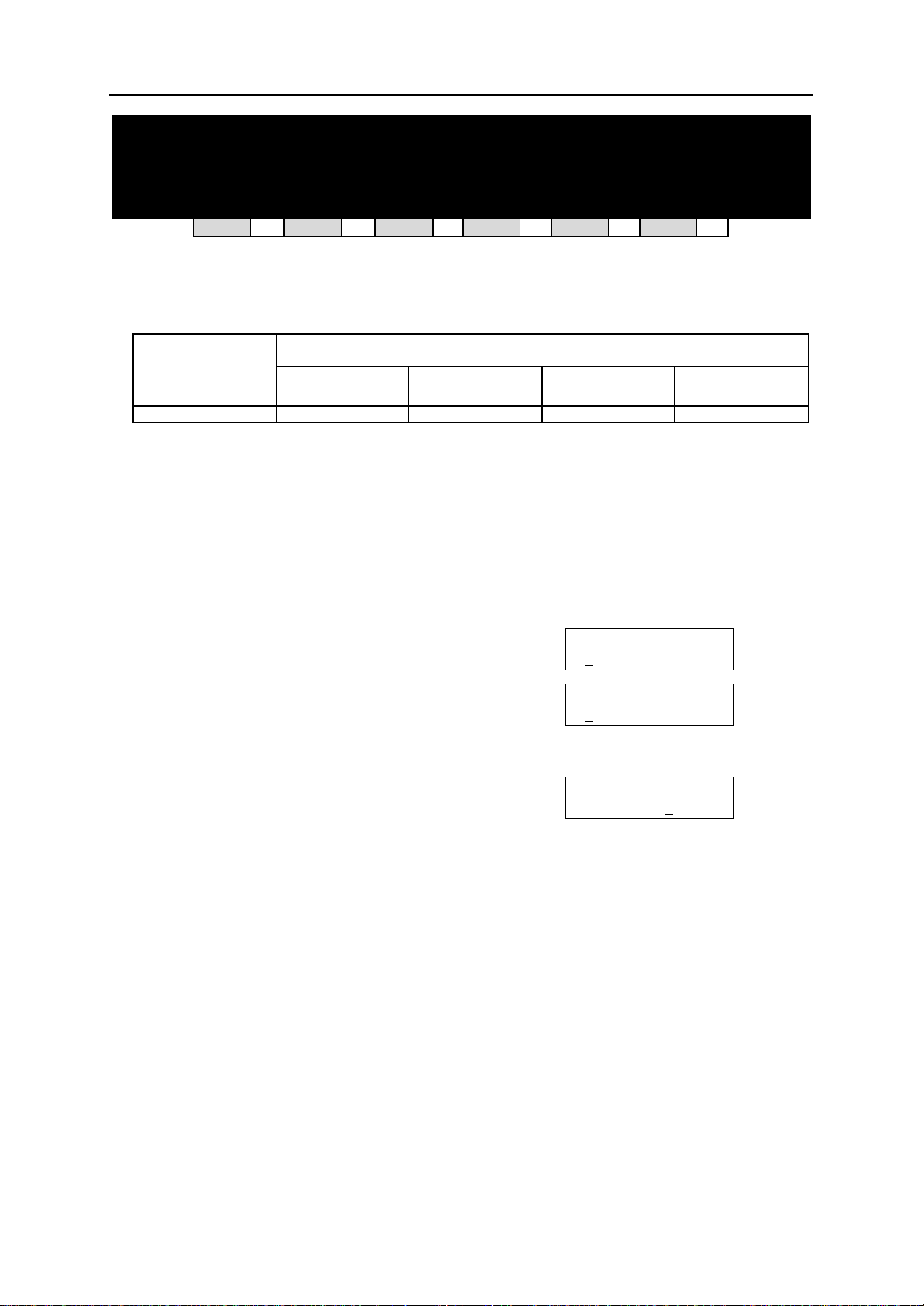
DCS MMC PROGRAMS
COMBINED PROGRAMMING MANUAL NOVEMBER 2001
MMC: 214 DISA ALARM RINGING
STATION
DCS
33
CI
33
CII
33
816
33
408i
33
408
33
Assigns the DISA alarm to ring at a specific phone. It is recommended that the person who can
clear the alarm also receives the notification. Both a day and a night destination can be selected.
A valid destination can be:
DEFAULT DIRECTORY NUMBER DEVICE
DCS Compact II 816 408/408i
Station 201–349 201–308 201–216 21–28
Station group 500–529 500–519 500–509 50–53
PROGRAM KEYS
UP & DOWN Used to scroll through options
KEYPAD Used to enter selections
SOFT KEYS Move cursor left and right
SPEAKER Used to store data and advance to next MMC
HOLD Used to clear previous entry
ACTION DISPLAY
1. Open programming and select 214
Display shows
2. Enter in valid day destination number (e.g., 212)
OR
Press UP or DOWN key to make selection
and press RIGHT soft key to advance cursor
3. Enter in valid night destination number (e.g., 205)
OR
Press UP or DOWN key to make selection
and press RIGHT soft key to return to step 2
4. Press TRSF to store and exit
OR
Press SPEAKER to store and advance to next MMC
Default Data: Day 500 (50 for 408/408i)
Night 500 (50 for 408/408i)
Related Items: MMC 202 Change Feature Passcodes
MMC 410 Assign DISA Trunk
DISA ALARM RING
D:500 N:500
DISA ALARM RING
D:212 N:500
DISA ALARM RING
D:212 N: 205
MMC 214 (Page 1 of 1)
Page 83
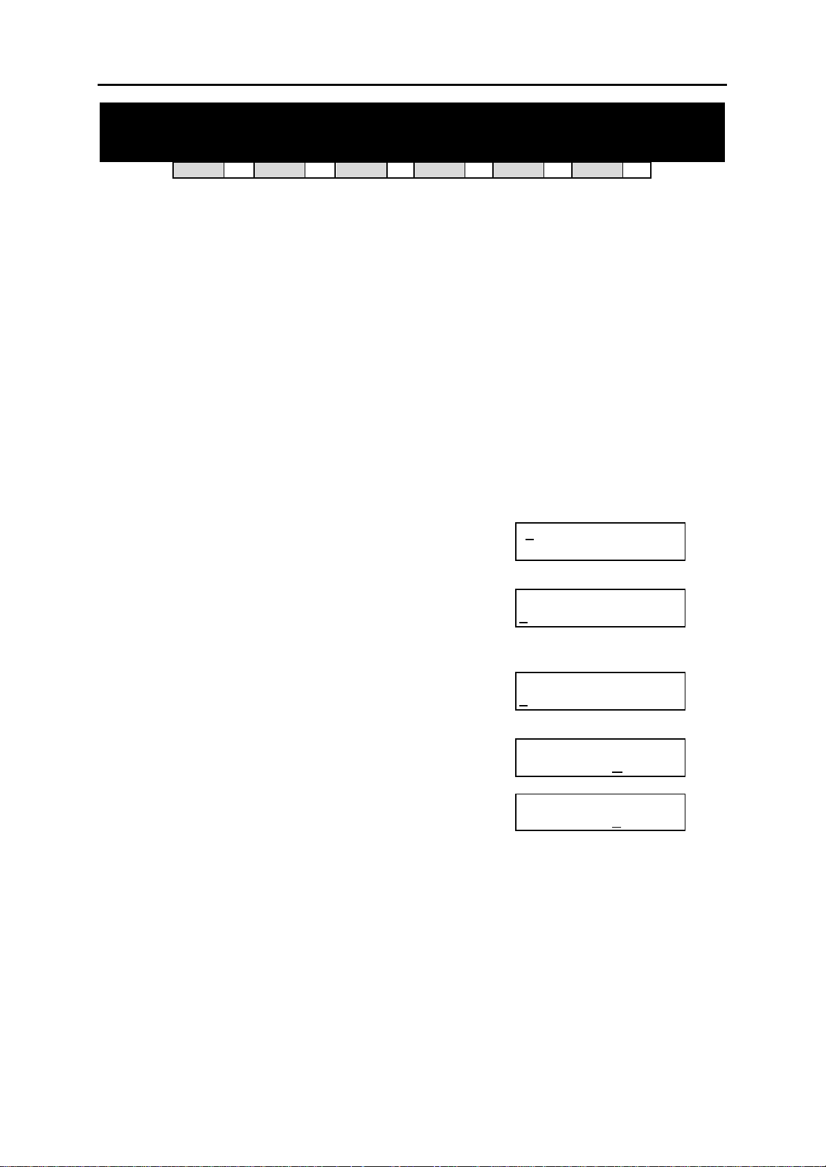
DCS MMC PROGRAMS
COMBINED PROGRAMMING MANUAL NOVEMBER 2001
MMC: 215 VOICE DIALLER OPTIONS
DCS
33
CI
33
CII
33
816
77
408i
77
408
77
Assigns the VDIAL card with two (2) channels and seven (7) users or one (1) channel and five (5) users. When changing channel size, you will be prompted to ‘clear RAM’. This is only for Voice Dialler,
not the system. This will prevent accidental usage of pre-recorded names. It is advised that you clear
RAM before assigning users in MMC 216, Voice Dialler Assignments.
VDIAL cards are numbered with odd numbers. For example, the first VDIAL card in the system is
numbered 3551 (DCS) or 355 (Compact II). The second channel, if used, will be numbered 3552 (or
356).The second VDIAL card is numbered 3553 (or 357), a nd a second channel 3554 (or 358). If only
one channel is assigned, the even number 3552 or 3554 (356 or 358) will not appear in MMC 216.
Option - 0 : 2CH-7USER-20BIN ( 7 USERS )
1 : 1CH-5USER-40BIN ( 5 USERS )
PROGRAM KEYS
UP & DOW N Used to scroll through options
KEYPAD Used to enter selections
SOFT KEYS Move cursor left and right
SPEAKER Used to store data and advance to next MMC
ACTION DISPLAY
1. Open programming and select 215
Display shows (3551 for DCS or 355 for CII,
e.g. 3551)
2. Enter Voice Dialler number, e.g. 3552, via dial keypad
OR
Press UP or DOWN key to make selection
Press RIGHT soft key to move cursor
3. Select channel option by pressing UP or DOWN key to
view selection
Press RIGHT soft key to make selection
4. Enter 0 for NO or 1 for YES
OR
Press UP and DOWN key to view selection
Press RIGHT soft key to make selection
5. Press TRSF to store and exit
OR
Press SPEAKER to store and advance
to next MMC
Default Data: 2CH-7USER-20BIN
Related Items: MMC 216 Voice Dialler Assignments
MMC 722 Station Key Programming
MMC 723 System Key Programming
MMC 724 Dial Numbering Plan
Keyset User Guide
551]VDIALER OPTN
[ 3
2CH-7USER -20BIN
[3552]VDIALER OPTN
2CH-7USER -20BIN
[3552]VDIALER OPTN
1CH-5USER -40BIN
[3552]VDIALER OPTN
CLEAR RAM? NO
[3552]VDIALER OPTN
CLEAR RAM? YES
MMC 215 [DCS / Compact II] (Page 1 of 1)
Page 84
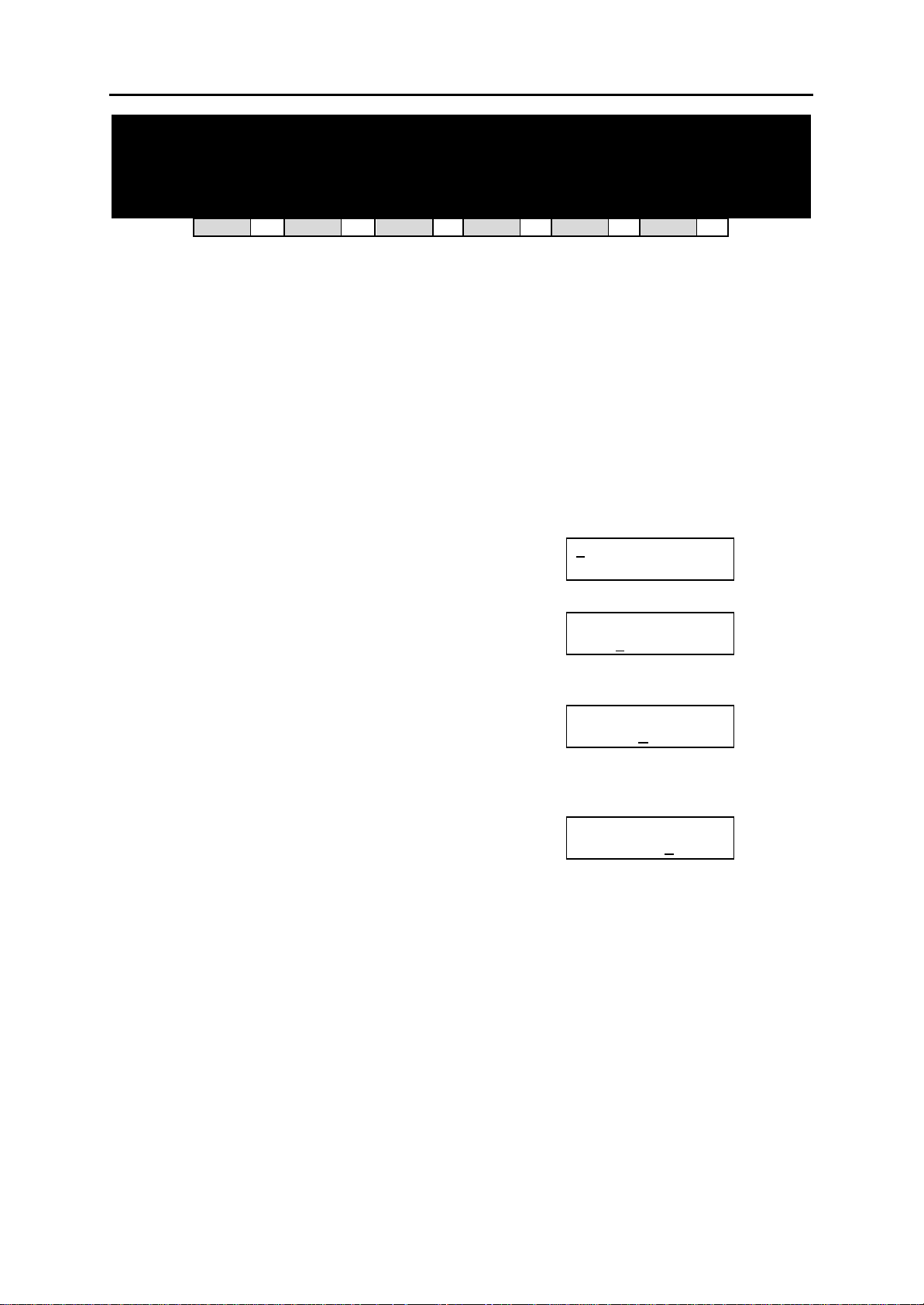
DCS MMC PROGRAMS
COMBINED PROGRAMMING MANUAL NOVEMBER 2001
MMC: 216 VOICE DIALLER
ASSIGNMENTS
DCS
33
CI
33
CII
33
816
77
408i
77
408
77
Allows a station to be assigned to a channel of the VDIAL card, to dial a personal speed dial
number. The number of users assigned to this feature is controlled by MMC 215, Voice Dialler
Options, which allows either two (2) channels with seven (7) users or one (1) channel with five (5)
users.
PROGRAM KEYS
UP & DOWN Used to sc roll through options
KEYPAD Used to enter selections
SOFT KEYS Move cursor left and right
SPEAKER Used to store data and advance to next MMC
HOLD Used to clear previous entry
ACTION DISPLAY
1. Open programming and select 216
Display shows (DCS=3551, Compact II=355,
e.g. 355)
2. Enter Voice Dialler number (e.g. 356) via dial keypad
OR
Press UP or DOWN key to make selection
Press RIGHT soft key to move cursor
3. Enter user number (1-7/1-5) dependent on number of
users allowed via MMC 215 (e.g. 5)
OR
Press UP or DOWN key to make selection
Press RIGHT soft key to move cursor
4. Enter station number (e.g., 205) via dial keypad
OR
Press UP or DOWN key to make selection and press
RIGHT soft key to return to step 3 to continue with entries
5. Press TRSF to store and exit
OR
Press SPEAKER to store and advance to next MMC
55]VDIALER USER
[3
USER 1 : NONE
[356]VDIALER USER
USER 1 : NONE
[356]VDIALER USER
USER 5 : NONE
[356]VDIALER USER
USER 5 : 205
Default Data: NONE
Related Items: MMC 215 Voice Dialler Options
MMC 722 Station Key Programming
MMC 723 System Key Programming
MMC 724 Dial Numbering Plan
Keyset User Guide
MMC 216 [DCS / Compact II] (Page 1 of 1)
Page 85
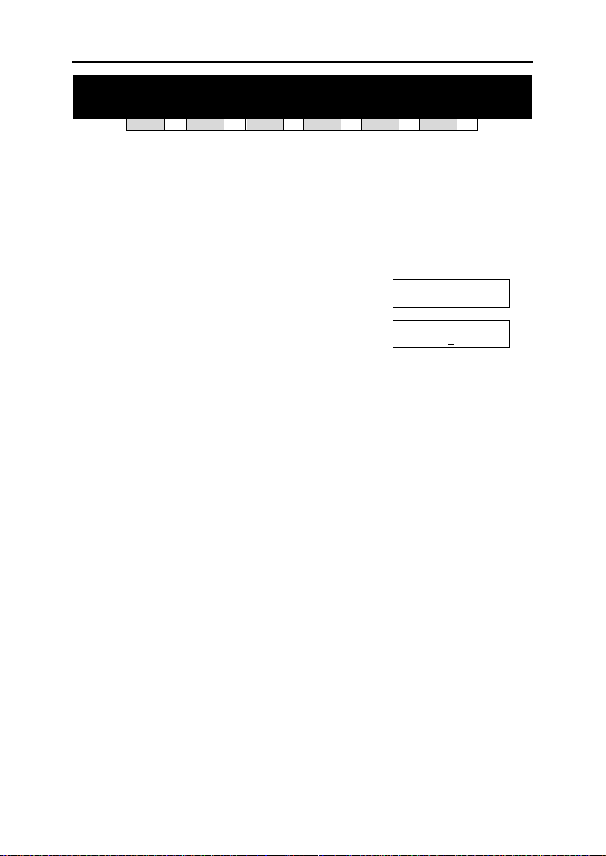
DCS MMC PROGRAMS
COMBINED PROGRAMMING MANUAL NOVEMBER 2001
MMC: 217 CCC OPTION
DCS
77
CI
33
CII
77
816
77
408i
77
Used to select Call Cost Option and is related only to 131 Cable & Wireless service.
PROGRAM KEYS
UP & DOWN Used to scroll through options
KEYPAD Used to enter selections
SOFT KEYS Move cursor left and right
SPEAKER Used to store data and advance to next MMC
ACTION DISPLAY
1. Open programming and select 217
Display shows
2. Use UP or DOWN to scroll through options
3. Press TRANSFER to store and exit
OR
Press SPEAKER to store and advance
to next MMC
Default Data: NONE
Related Items: MMC 313 Assign PIN Code
CCC OPTION
OPTION : NONE
CCC OPTION
OPTION : STATION #
408
77
MMC 217 [Compact I] (Page 1 of 1)
Page 86
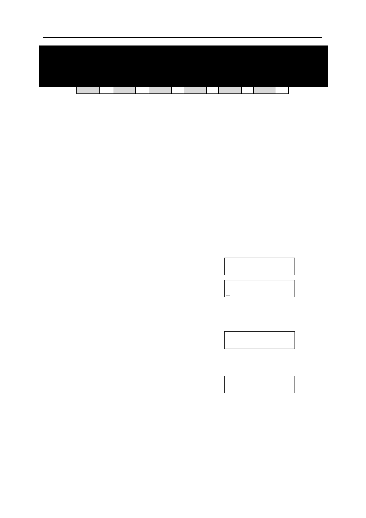
DCS MMC PROGRAMS
COMBINED PROGRAMMING MANUAL NOVEMBER 2001
MMC: 219 COMMON RELAY SERVICE
TYPE
DCS
77
CI
77
CII
33
816
33
408i
This MMC is used to define the function of :
• three common relays in the Compact II MISC card (363–365), or
• the common relay in the 816 base board (362), or
• the common relay in the 408/408i base board (361).
Each relay can be used for one of the fo llowing:
0 EXTERNAL PAGE
1 COMMON BELL
2 LOUD BELL
3 NOT US E
PROGRAM KEYS
UP & DOWN Used to scroll through options
KEYPAD Used to enter selections
SOFT KEYS Move cursor left and right
SPEAKER Used to store data and advance to next MMC
ACTION DISPLAY
1. Open programming and select 219
Display shows (e.g. 363)
2.
Compact II only – dial relay number (e.g. 364)
OR
Use UP or DOWN to scroll through numbers and
press RIGHT soft key to move cursor
816/408/408i – press RIGHT soft key to move cursor
3. Dial relay function 0–3 (see table above)
OR
Press UP or DOWN to scroll through options
and press RIGHT soft key
4.
Compact II only–Repeat step 2 for next relay
5. Press TRSF to store and exit
OR
Press SPEAKER to store and advance to next MMC
Default Data: EXTERNAL PAGE
Related Items: MMC 203 Assign UA Device
MMC 204 Common Bell Control
MMC 205 Assign Loud Bell
MMC 605 Assign External Page Zone
[363]RELAY TYPE
EXTERNAL PAGE
[364]RELAY TYPE
EXTERNAL PAGE
[364]RELAY TYPE
LOUD BELL
[364]RELAY TYPE
NOT USE
33
408
33
MMC 219 [Compact II / 816] (Page 1 of 1)
Page 87
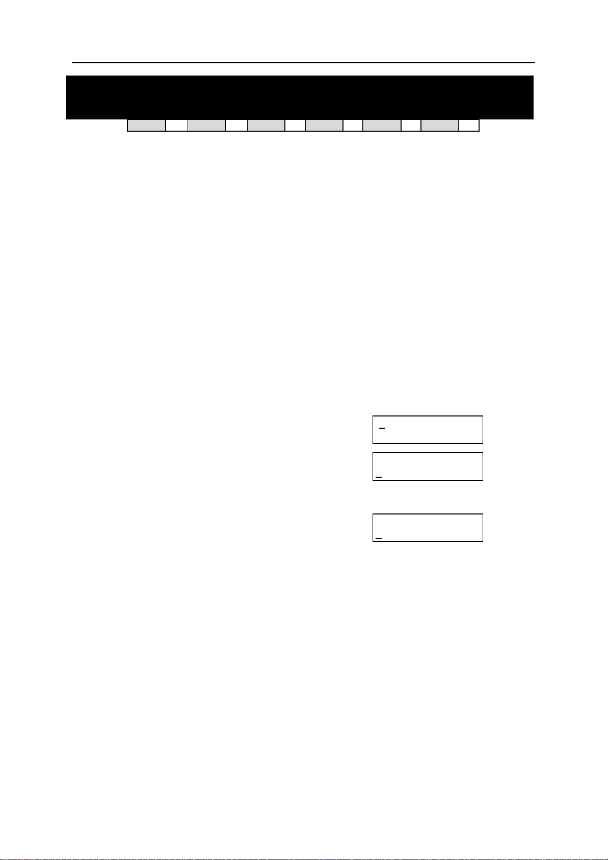
DCS MMC PROGRAMS
COMBINED PROGRAMMING MANUAL NOVEMBER 2001
MMC: 220 ISDN SERVICE TYPE
DCS
33
CI
33
CII
33
816
33
408i
33
408
77
Assigns the ISDN service type for SLT stations. Services consist of BC (Bearer Capability) and
HLC (High Layer Capability).
TYPE DESCRIPTION BC HLC
0 VOICE Voice service Speech Telephony
1 FAX 3 G3 FAX service 3.1kHz Audio FAX G2/G3
2 AUDIO 3.1 3.1kHz Audio service 3.1kHz Audio None
3 MODEM MODEM service 3.1kHz Audio Telephony
PROGRAM KEYS
UP & DOWN Used to scroll through options
KEYPAD Used to enter selections
SOFT KEYS Move cursor left and right
SPEAKER Used to store data and advance to next MMC
HOLD Used to clear previous entry
ACTION DISPLAY
1. Open programming and select 220
Display shows
2. Dial station number (SLT only) (e.g., 215)
OR
Press UP or DOWN to select station
and press RIGHT soft key to move cursor
3. Select service type 0 - 3 (e.g. 2)
OR
Press UP or DOWN to select option and press
RIGHT soft key
4. Press TRSF to store and exit
OR
Press SPEA KER to store and advance to next MMC
Default Data: VOICE
Related Items: None
13] ISDN SRV
[2
VOICE
[215] ISDN SRV
VOICE
[215] ISDN SRV
AUDIO 3.1
MMC 220 (Page 1 of 1)
Page 88

DCS MMC PROGRAMS
COMBINED PROGRAMMING MANUAL NOVEMBER 2001
MMC: 300 CUSTOMER ON/OFF PER
STATION
DCS
33
CI
33
CII
33
816
33
408i
33
408
33
Allows the following features to be enabled on individual stations.
ACCESS DIAL Determines whether a user can select a trunk or trunk group by dial-
ling its directory number (DN). This selection should be turned OFF
when using LCR.
MICROPHONE Allows keyset to be used in speakerphone mode.
OFF-HOOK RING Allows a short burst of ring tone to indicate another call.
SMDR PRINT When this is set OFF, C.O. calls to and from the station will not print
on SMDR. This includes transferred calls or calls picked up from
hold or park.
TGR ADV.TONE When this feature is set to ON, a warning tone will be heard each
time LCR advances to the next route.
VMAA FORWARD When this feature is set to ON, it allows calls to be forwarded to
voice mail.
STN CALL PRT Allows print out of station to station call.
FWD DLY USE When this feature is set to ON, calls will overflow to Forward No An-
swer destination when the Forward No Answer timer expires even
when the Forward No Answer feature is not activated at the called
party extension.
Set Forward No Answer destination in MMC 102, Call Forward , but
do not enable the feature. (Alternatively, use code 603 plus the st a-
tion number, then code 600 to cancel the feature.)
PROGRAM KEYS
UP & DOWN Used to scroll through options
KEYPAD Used to enter selections
SOFT KEYS Move cursor left and right
SPEAKER Used to store data and advance to next MMC
HOLD Used to clear previous entry
ANS/RLS Used to select ALL
MMC 300 (Page 1 of 2)
Page 89

DCS MMC PROGRAMS
COMBINED PROGRAMMING MANUAL NOVEMBER 2001
ACTION DISPLAY
1. Open programming and select 300
Display shows
2. Dial station number (e.g., 205)
OR
Press UP or DOWN to select station
OR
Press ANS/RLS for all and press RIGHT soft key to
move cursor
3. Press UP or DOWN to select feature and
press RIGHT soft key to move cursor
4. Dial 1 for ON or 0 for OFF
OR
Press UP or DOWN to select ON/OFF and press RIGHT
soft key
5. Press LEFT soft key to return to step 2
Press RIGHT soft key to return to step 1
OR
Press TRSF to store and exit
OR
Press SPEAKER to store and advance to next MMC
Default Data: STN CALL PRT : OFF
FWD DLY USE : OFF
All other features set to ON
Related Items: LCR programming
[201] CUS.ON/OFF
ACCESS DIAL :ON
[205] CUS.ON/OFF
ACCESS DIAL :ON
[ALL] CUS.ON/OFF
ACCESS DIAL :ON
[ALL] CUS.ON/OFF
ACCESS DIAL :ON
[ALL] CUS.ON/OFF
ACCESS DIAL :OFF
MMC 300 (Page 2 of 2)
Page 90
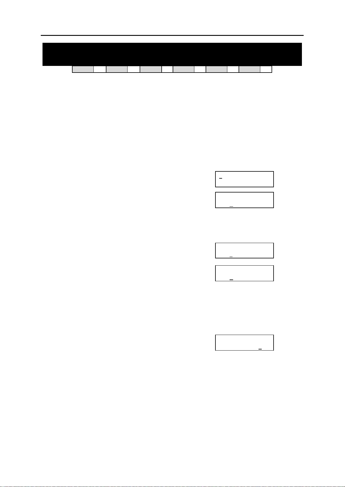
DCS MMC PROGRAMS
COMBINED PROGRAMMING MANUAL NOVEMBER 2001
MMC: 301 ASSIGN STATION COS
DCS
33
CI
33
CII
33
816
33
408i
33
408
33
Used to assign a day and night class of service to each station. A number of different classes of
service can be defined in MMC 701, Assign COS Contents—i.e. 30 for DCS/Compact II systems
(01–30), 10 for 816 systems (01–10) and four for 408/408i systems (1–4).
PROGRAM KEYS
UP & DOWN Used to scroll through options
KEYPAD Used to enter selections
SOFT KEYS Move cursor left and right
SPEAKER Used to store data and advance to next MMC
HOLD Used to clear previous entry
ANS/RLS Used to select ALL
ACTION DISPLAY
1. Open programming and select 301
Display shows
2. Dial station number (e.g., 205)
OR
Press UP and DOWN to scroll through stations and press
RIGHT soft key to advance to step 3 to enter Day COS
OR
Press UP and DOWN to scroll through stations and press
LEFT soft key to advance to step 4 to enter Night COS
OR
Press ANS/RLS to select all stations
3. Enter day class of service (e.g., 05)
OR
Press UP and DOWN to scroll through classes of service
and press RIGHT soft key to advance to step 4 to enter
Night COS
OR
Press UP and DOWN to scroll through classes of service
and press LEFT soft key to return to step 2 to enter other
stations
4. Enter night class of service (e.g., 05)
OR
Press UP and DOWN to scroll through classes of service
and press RIGHT soft key to return to step 2 to enter
other stations
OR
Press UP and DOWN to scroll through classes of service
and press LEFT soft key to return to step 3
5. Press TRSF to save and exit
OR
Press SPEAKER to save and advance to next MMC
Default Data: Day class = 01 (or 1)
Night class = 01 (or 1)
Related Items: MMC 701 Assign COS Contents
01] STN COS
[2
DAY:01 NIGHT:01
[205] STN COS
DAY:01 NIGHT: 01
OR
[ALL] STN COS
DAY:?? NIGHT:??
[205] STN COS
DAY:05 NIGHT:01
[205] STN COS
DAY:05 NIGHT:05
MMC 301 (Page 1 of 1)
Page 91
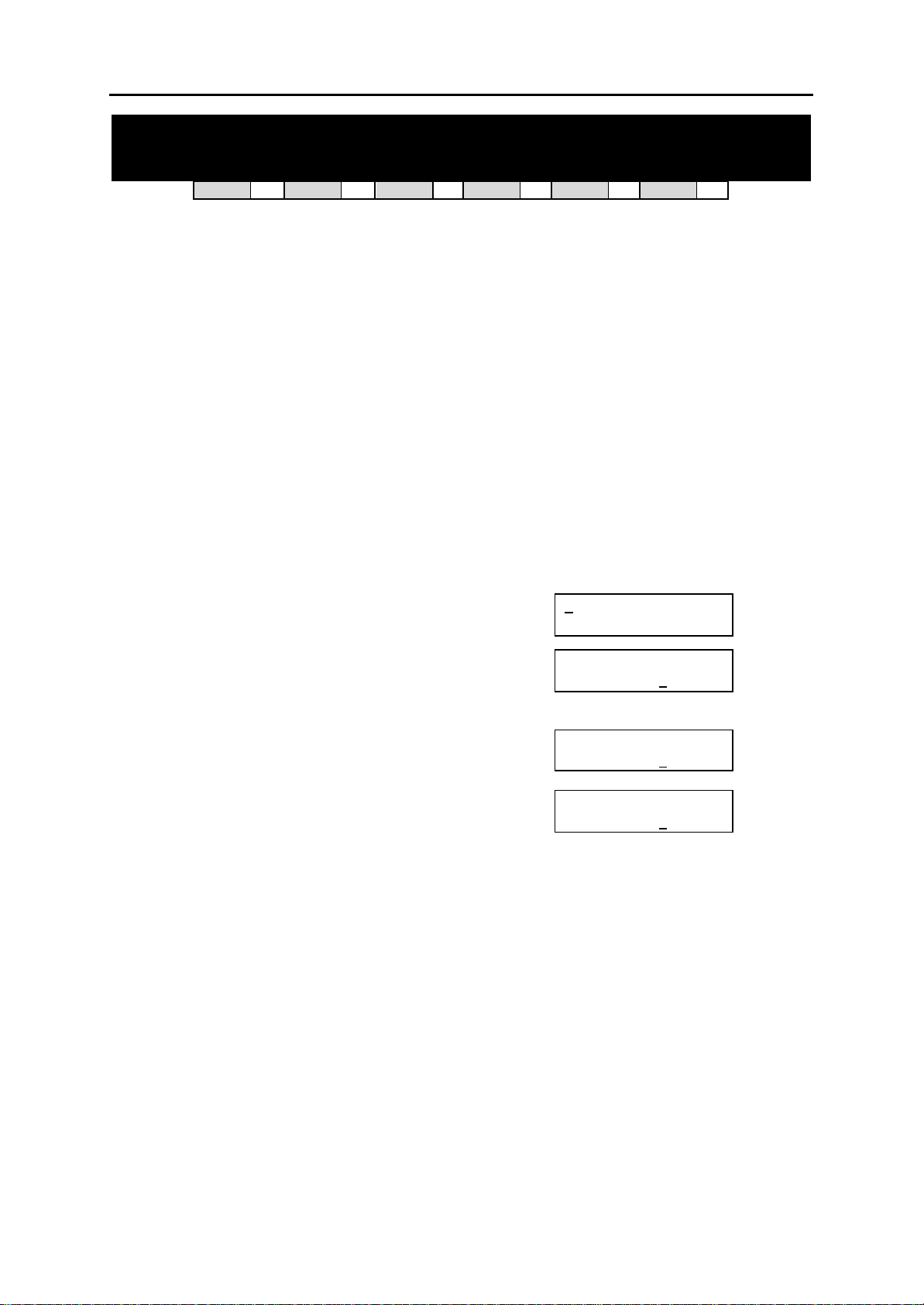
DCS MMC PROGRAMS
COMBINED PROGRAMMING MANUAL NOVEMBER 2001
MMC: 302 PICKUP GROUPS
DCS
33
CI
33
CII
33
816
33
408i
33
408
33
Allows the assignment of stations into call pickup groups. Maximum number of pickup groups is:
DCS and Compact II – 20
816 – 8
408/408i – 4
An unlimited number of members can belong to each group. Stations can only be in one pickup
group at any given time.
PROGRAM KEYS
UP & DOWN Used to scroll through options
KEYPAD Used to enter selections
SOFT KEYS Move cursor left and right
SPEAKER Used to store data and advance to next MMC
HOLD Used to clear previous entry
ANS/RLS Used to select ALL
ACTION DISPLAY
1. Open programming and select 302
Display shows
2. Dial station number ( e.g., 205)
OR
Use UP or DOWN to select station number and
press RIGHT soft key
OR
Press ANS/RLS key to select all
3. Dial pickup group number (e.g. 04)
OR
Press UP or DOWN to select group number
4. Press RIGHT soft key to return to step 2 to enter more
stations
OR
Press LEFT soft key to return to step 3
OR
Press TRSF to store and exit
OR
Press SPEAKER to store and advance to next MMC
Default Data: All stations = group 01
Related Items: MMC 107 Key Extender
MMC 722 Station Key Programming
MMC 723 System Key Programming
01] PICKUP GRP
[2
PICKUP GRP :01
[205] PICKUP GRP
PICKUP GRP :01
OR
[ALL] PICKUP GRP
PICKUP GRP :??
[205] PICKUP GRP
PICKUP GRP :04
MMC 302 (Page 1 of 1)
Page 92
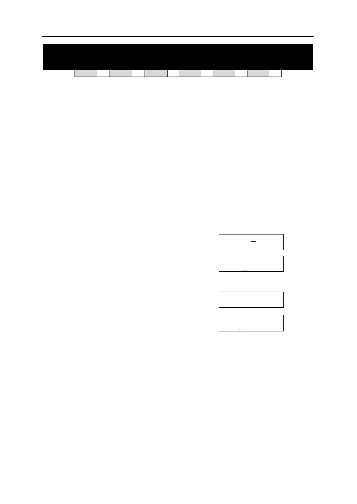
DCS MMC PROGRAMS
COMBINED PROGRAMMING MANUAL NOVEMBER 2001
MMC: 303 ASSIGN BOSS/SECRETARY
DCS
Assigns BOSS stations to SECRETARY stations. One BOSS station can have up to four SECR ETARY stations, and one SECRETARY station can have up to four BOSS stations.* A dedicated
BOSS key must be programmed on the SECRETARY keyset(s). A dedicated BOSS key must
also be programmed on the BOSS keyset(s).
*Note: For 408/408i systems, a BOSS station can have up to two SECRETARY stations, and vice versa.
PROGRAM KEYS
UP & DOWN Used to scroll through options
KEYPAD Used to enter selections
SOFT KEYS Move cursor left and right
SPEAKER Used to store data and advance to next MMC
HOLD Used to clear previous entry
ANS/RLS Used to select ALL
“F” Key #24 (24B keyset) or key #12 (12B keyset) or key #6 (6B keyset) is used
ACTION DISPLAY
1. Open programming and select 303
Display shows
2. Dial BOSS station number (e.g., 205)
OR
Press UP or DOWN to select station and press RIGHT
soft key
3. Dial SECRETARY station number (e.g., 201)
OR
Press UP or DOWN to select station
Press RIGHT soft key to return to step 3 to enter more
SECR numbers
4. Press LEFT soft key to return to step 2 and continue
entries
OR
Press TRSF to store and exit
OR
Press SPEAKER to store and advance to next MMC
Default Data: NONE
Related Items: MMC 722 Stati on Key Programming
33
CI
to toggle BOSS/SECRETARY field
33
CII
33
816
33
408i
BOSS STN: N
SECR 1:NONE
BOSS STN :205
SECR 1:NONE
BOSS STN:205
SECR 1:201
BOSS STN:205
SECR 2:202
33
408
ONE
33
MMC 303 (Page 1 of 1)
Page 93
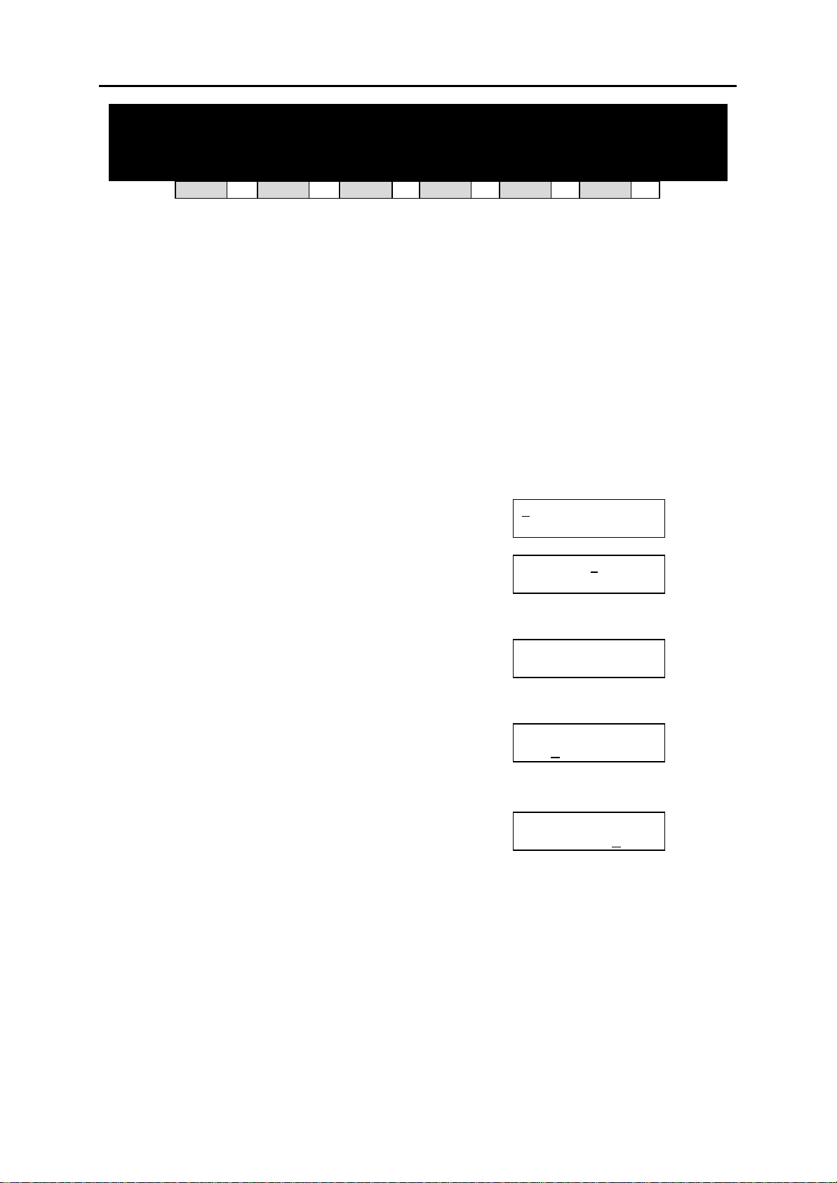
DCS MMC PROGRAMS
COMBINED PROGRAMMING MANUAL NOVEMBER 2001
MMC: 304 ASSIGN STATION /
TRUNK USE
DCS
Allows trunks, on a per-station basis, to answer incoming calls, to dial out or to do both. If a st ation is set to DIAL:NO, the station will not have the ability to place a call. If the station is set to
ANS:NO, the station cannot answer an incoming call.
Note: MMC 406, Trunk Ring Assignment , overrides this MMC for the Answer option.
PROGRAM KEYS
UP & DOWN Used to scroll through options
KEYPAD Used to enter selections
SOFT KEYS Move cursor left and right
SPEAKER Used to store data and advance to next MMC
HOLD Used to clear previous entry
ANS/RLS Used to select ALL
ACTION DISPLAY
1. Open programming and select 304
Display shows
2. Dial the station number (e.g., 205)
OR
Press UP or DOWN key to select station and press
RIGHT soft key
3. Dial the trunk ID number (e.g., 704)
OR
Press UP or DOWN key to select trunk and press
RIGHT soft key
4. Press UP or DOWN key to select YES/NO option
OR
Dial 1 for YES or 0 for NO and press RIGHT soft key
to move cursor to ANS option
Press UP or DOWN key to select YES/NO
Option
OR
Dial 1 for YES or 0 for NO and press RIGHT soft key
to return to step 2
5. Press TRSF to store and exit
OR
Press SPEAKER to store and advance to next MMC
Default Data: DIAL = YES
ANS = YES
Related Items: MMC 316 Copy Station Usable
MMC 406 Trunk Ring Assignment
MMC 722 Station Key Programming
MMC 723 System Key Programming
33
CI
33
CII
33
816
33
408i
[2
DIAL:YES ANS:YES
[205] USE [7
DIAL:YES ANS:YES
[205] USE [704]
DIAL:YES ANS:YES
[205] USE [704]
DIAL:NO ANS:YES
[205] USE [704]
DIAL:NO ANS:NO
33
01] USE [701]
408
01]
33
MMC 304 (Page 1 of 1)
Page 94
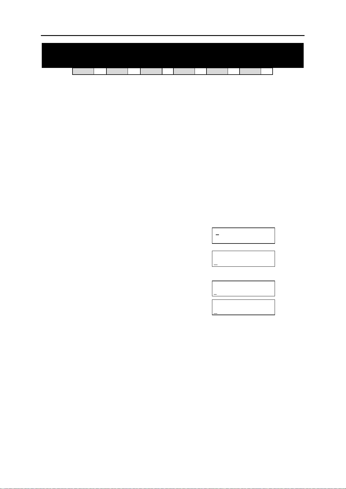
DCS MMC PROGRAMS
COMBINED PROGRAMMING MANUAL NOVEMBER 2001
MMC: 305 ASSIGN FORCED CODE
DCS
Allows the assignment of either account or authorisation codes on a per-station basis or on an
all-station basis.
PROGRAM KEYS
UP & DOWN Used to scroll through options
KEYPAD Used to enter selections
SOFT KEYS Move cursor left and right
SPEAKER Used to store data and advance to next MMC
ANS/RLS Used to select ALL
FEATURE KEYS
0 NONE
1 AUTHORISE CODE
2 ACCOUNT CODE
ACTION DISPLAY
1. Open programming and select 305
Display shows
2. Dial station number ( e.g., 205)
OR
Press UP or DOWN key to select station and press
RIGHT soft key to move cursor
OR
Press ANS/RLS to select all stations
3. Dial a feature option 0–2 (e.g., 2)
OR
Press UP or DOWN key to select option
and press RIGHT soft key to return step 2
4. Press TRSF to store and exit
OR
Press SPEAKER to store and advance to next MMC
Default Data: None
Related Items: MMC 707 Authorisation Code
MMC 708 Account Code
33
CI
33
CII
33
816
33
408i
[2
NONE
[205] FORCD CODE
NONE
OR
[ALL] FORCD CODE
?
[205] FORCD CODE
ACCOUNT CODE
33
01] FORCD CODE
408
33
MMC 305 (Page 1 of 1)
Page 95
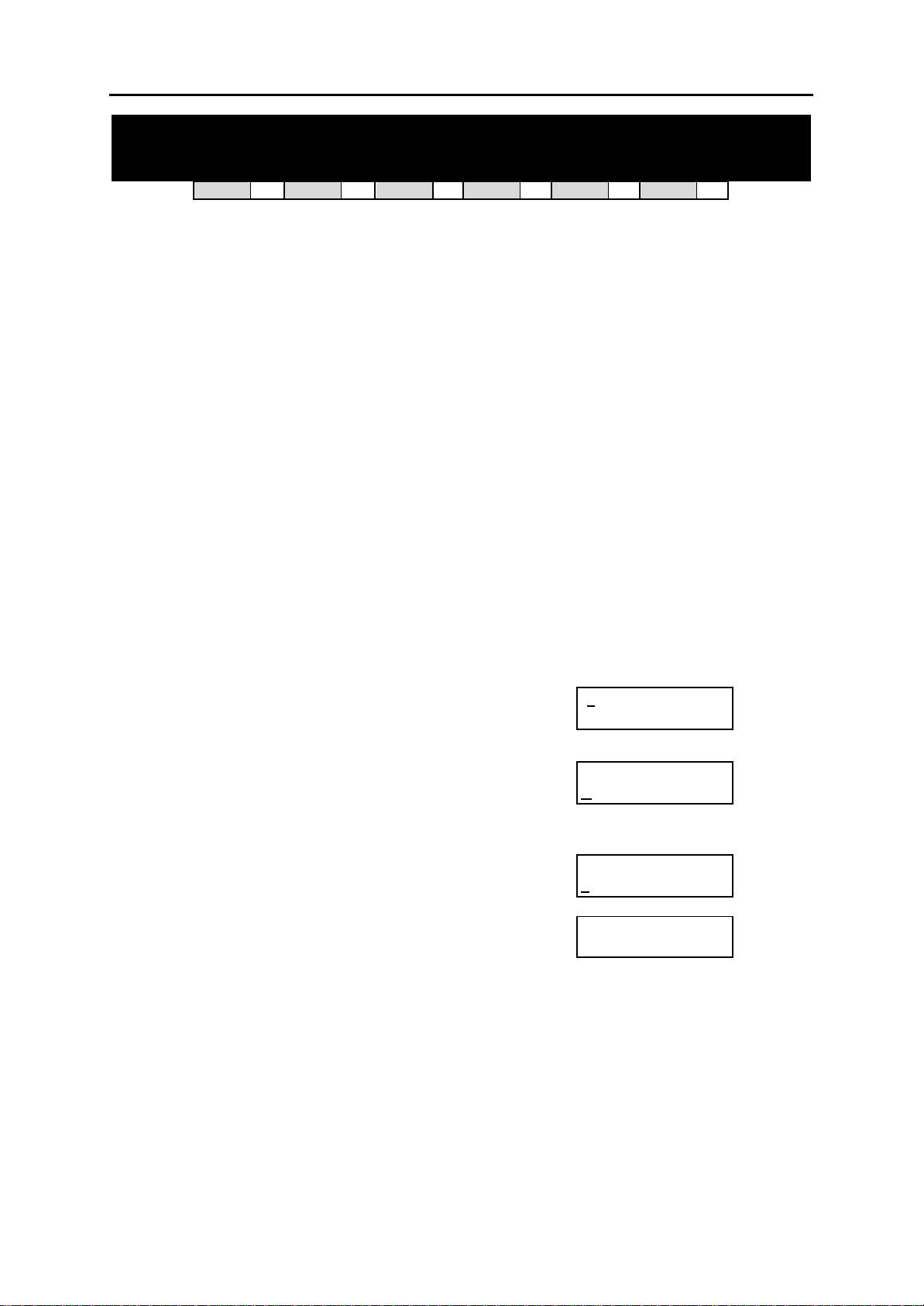
DCS MMC PROGRAMS
COMBINED PROGRAMMING MANUAL NOVEMBER 2001
MMC: 306 HOT LINE
DCS
33
CI
33
CII
33
816
33
408i
33
408
33
Allows a station to make an automatic internal or external call upon the expiration of a timer (see
MMC 501, System-Wide Timers: ‘Off-Hook Select Timer’ option) to a predetermined number
when the handset is lifted. The number can be a maximum of 18 digits including pauses, flash
etc., in the dial string (the access code for a trunk is not counted).
PROGRAM KEYS
UP & DOWN Used to scroll through options
KEYPAD Used to enter selections
SOFT KEYS Move cursor left and right
SPEAKER Used to store data and advance to next MMC
HOLD Used to clear previous entry
ANS/RLS Used to select ALL
“B” Used to insert a flash code “F”
”C” Used to insert a pause code “P”
”D” Used to insert a pulse/tone conversion code “C”
”E” Used to mask/unmask following digits (shows as “[” or “]”)
Keys “A” to “F” are keys #19 to #24 on 24B keysets, or keys #7 to #12 on 12B keysets, or keys
#1 to #6 on 6B keysets.
ACTION DISPLAY
1. Open programming and select 306
Display shows
Press RIGHT soft key to advance cursor
2. Enter station number via dial keypad (e.g. 201)
OR
Press UP or DOWN to make selection and press RIGHT
soft key
2. Enter station number to automatically dial via keypad
(e.g. 202)—or press UP or DOWN to select
OR
Enter a trunk to automatically dial (e.g. 701)—or press UP
or DOWN to select—then press the RIGHT soft key and
enter a maximum of 18 digits to dial.
3. Press RIGHT soft key to return to step 2
4. Press TRSF to store and exit
OR
Press SPEAKER to store and advance to next MMC
01] HOT LINE
[2
NONE
[201] HOT LINE
NONE
[201] HOT LINE
202
[201] HOT LINE
701-01235987654_
Default Data: NONE
Related Items: MMC 501 System -Wide Timers (Off-Hook Select Timer)
MMC 306 (Page 1 of 1)
Page 96
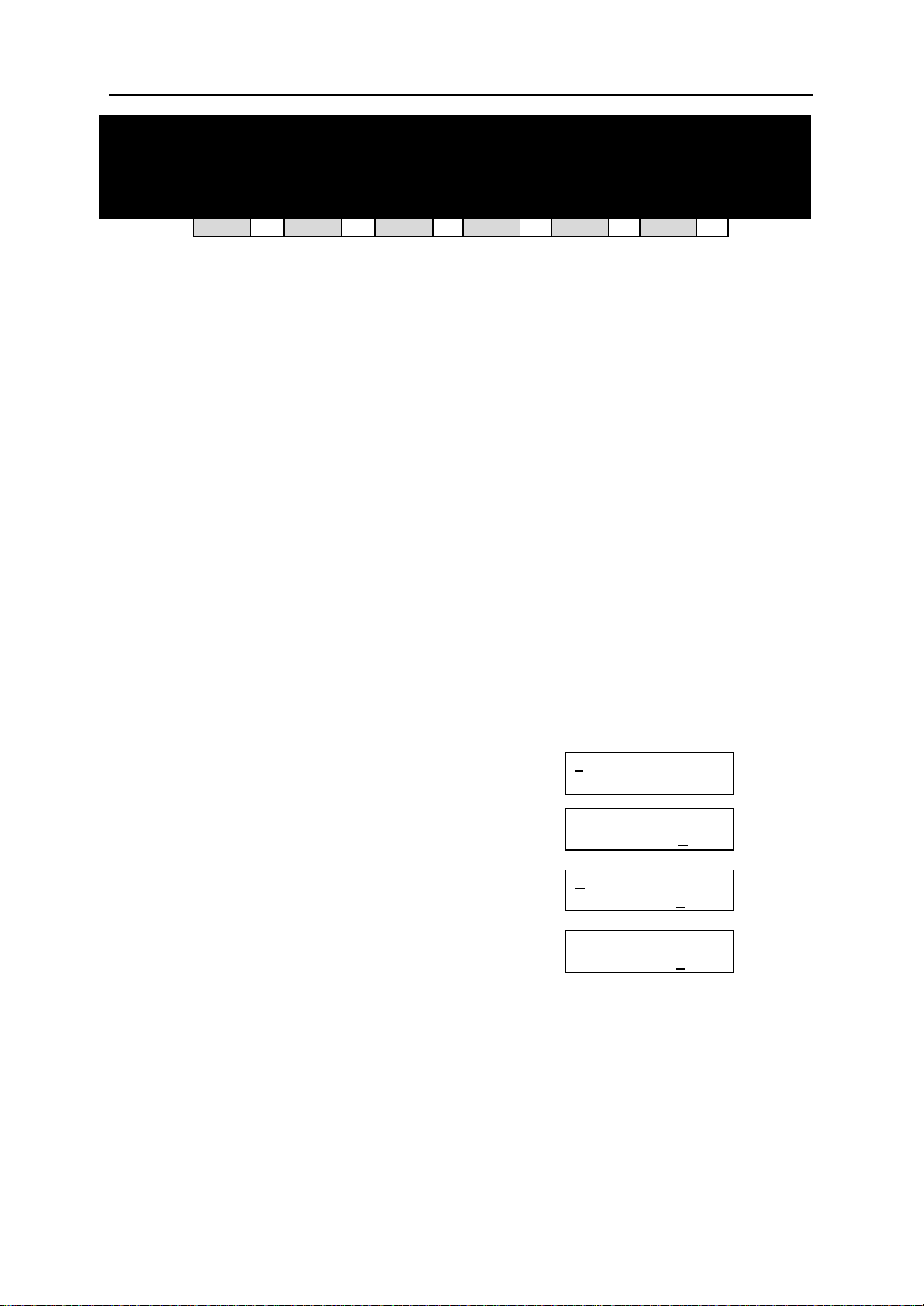
DCS MMC PROGRAMS
COMBINED PROGRAMMING MANUAL NOVEMBER 2001
MMC: 308 ASSIGN BACKGROUND MUSIC SOURCE
DCS
33
CI
33
CII
33
816
33
408i
33
408
33
Assigns a background music (BGM) source to keysets as follows.
DCS –There is a total of 19 possible music selections, but this is dependent on the number of
Trunk A cards that are installed in the system. Only one music source is provided per Trunk A
card. The system must have a Trunk A card installed to provide a BGM source. The default directory number of a BGM source is 3701–3719. (Internal music is always the odd numbered address, e.g. 3701, 3703.)
Compact II–There is a total of two possible music selections, but this depends on whether a
Misc card is installed in the system. One music source is provided on the base board (switch select internal/external); the other external source is provided on the Misc card. The default directory number of a BGM source is 371–372.
816 and 408/408i –There is a music source on the base board (switch select internal/external).
The default directory number of a background music source is 371.
PROGRAM KEYS
UP & DOWN Used to scroll through options
KEYPAD Used to enter selections
SOFT KEYS Move cursor left and right
SPEAKER Used to store data and advance to next MMC
HOLD Used to clear previous entry
ANS/RLS Used to select ALL
ACTION DISPLAY
1. Open programming and select 308
Display shows current setting
2. Dial keyset number (e.g., 205)
OR
Use UP or DOWN to scroll through keyset numbers
and press RIGHT soft key to move the cursor
OR
Press ANS/RLS to select all stations
3. Enter source number (e.g., 3701)
OR
Press UP or DOWN key to make selection and press
RIGHT soft key to return to step 2
4. Press TRSF to store and exit
OR
Press SPEAKER to store and advance to next MMC
Default Data: NONE
Related Items: MMC 309 Assign Station Music On Hold
MMC 408 Assign Trunk Music On Hold Source
01] BGM SOURCE
[2
BGM SOURCE:NONE
[205] BGM SOURCE
BGM SOURCE: NONE
OR
[A
LL] BGM SOURCE
BGM SOURCE:?
[205] BGM SOURCE
BGM SOURCE:3701
MMC 308 (Page 1 of 1)
Page 97
DCS MMC PROGRAMS
COMBINED PROGRAMMING MANUAL NOVEMBER 2001
MMC: 309 ASSIGN STATION MUSIC
ON HOLD
DCS
33
CI
33
CII
33
816
33
408i
33
408
33
Allows the system administrator to select which Music On Hold (MOH) source can be heard on
each station. There are four possible selections for each music source: TONE, NONE, internal
and external (customer -provided MOH source).
DCS–The system must have a Trunk A card installed to provide a music source. There is a total
of 19 possible music selections, but this is dependent on the number of Trunk A cards in the sy stem. Only one external music source is provided per Trunk A card. The default directory number
of a music source is 3701–3719. (Internal music is always the odd numbered address, e.g. 3701,
3703.)
Compact II– There is a total of two possible music sources, but this depends on whether a MISC
card is installed in the system. One music source is provided on the base board (switch select internal/external); the other external source is provided on the MISC card. The default directory
number of a background music source is 371–372. (Internal music is always address 371.)
816 and 408/408i –There is a music source on the base board (switch select internal/external).
The default directory number of a background music source is 371.
PROGRAM KEYS
UP & DOWN Used to scroll through options
KEYPAD Used to enter selections
SOFT KEYS Move cursor left and right
SPEAKER Used to store data and advance to next MMC
HOLD Used to clear previous entry
ANS/RLS Used to select ALL
ACTION DISPLAY
1. Open programming and select 309
Display shows current setting
2. Dial keyset number (e.g., 205)
OR
Use UP or DOWN to scroll through keyset numbers and
press RIGHT soft key to move the cursor
OR
Press ANS/RLS to select all stations
3. Enter source number (e.g., 371)
OR
Press UP or DOWN key to make selection and press
RIGHT soft key to return to step 2
4. Press TRSF to store and exit
OR
Press SPEAKER to store and advance to next MMC
01] STN MOH
[2
MOH SOURCE:TONE
[205] STN MOH
MOH SOURCE: TONE
OR
[ALL] STN MOH
MOH SOURCE:?
[205] STN MOH
MOH SOURCE:371
Default Data: None
Related Items: MMC 308 Assign Background Music Source
MMC 408 Assign Trunk Music On Hold Source
MMC 309 (Page 1 of 1)
Page 98
DCS MMC PROGRAMS
COMBINED PROGRAMMING MANUAL NOVEMBER 2001
MMC: 310 LCR CLASS OF SERVICE
DCS
33
CI
33
CII
33
816
33
408i
33
408
33
Assigns the LCR class of service allowed for a station on a per-station basis. Eight classes (1–8)
can be assigned. (408/408i systems have four classes, 1–4.)
PROGRAM KEYS
UP & DOWN Used to scroll through options
KEYPAD Used to enter selections
SOFT KEYS Move cursor left and right
SPEAKER Used to store data and advance to next MMC
HOLD Used to clear previous entry
ANS/RLS Used to select ALL
ACTION DISPLAY
1. Open programming and select 310
Display shows
2. Dial station number (e.g., 205)
OR
Press UP or DOWN to select station and press
RIGHT soft key to move cursor
OR
Press ANS/RLS to select All stations
3. Dial 1–8 to select class type (e.g. 3)
OR
Press UP or DOWN to select class type and
press RIGHT soft key to return to step 2
4. Press TRSF to store and exit
OR
Press SPEAKER to store and advance to next MMC
01] LCR CLASS
[2
LCR CLASS 1
[205] LCR CLASS
LCR CLASS 1
OR
[ALL] LCR CLASS
LCR CLASS ?
[205] LCR CLASS
LCR CLASS 3
Default Data: Least Cost Routing COS 1
Related Items: LCR programming
MMC 310 (Page 1 of 1)
Page 99
DCS MMC PROGRAMS
COMBINED PROGRAMMING MANUAL NOVEMBER 2001
MMC: 311
DCS
ASSIGN SIM PARAMETER
✓✓✓✓
CI
✗✗✗✗
CII
✗✗✗✗
816
✗✗✗✗
408i
✗✗✗✗
408
✗✗✗✗
Assigns and sets parameters for the serial interface module (SIM). Refer to tables 1–12, below.
PROGRAM KEYS
UP & DOWN Used to scroll through options
KEYPAD Used to enter selections
SOFT KEYS Move cursor left and right
SPEAKER Used to store data and advance to next MMC
HOLD Used to clear previous entry
ACTION DISPLAY
1. Open programming and select 311
Display shows
2. Enter station number connected to SIM (e.g., 257)
from dial keypad
OR
Press UP or DOWN key to make selection and press
RIGHT soft key to move cursor
3. Enter desired selection from table 1 (00–10, e.g. 01)
OR
Press UP or DOWN key to make selection and press
RIGHT soft key to move cursor
Refer to table 1 for your selected option and go to
the table indicated (e.g. 3) to enter required
value (e.g. 0) using dial keypad or by pressing UP or
DOWN key
Press RIGHT soft key to move cursor
4. Repeat step 3 for all required options (00–10 in table 1)
[2
56] SIM PARA
SIM TYPE :DTE
[257] SIM PARA.
SIM TYPE :DTE
[257] SIM PARA.
CALL MODE:AWITH
[2
57] SIM PARA.
CALL MODE:MANUAL
5. Press TRSF to store and exit
OR
Press SPEAKER to store and advance to next MMC
TABLE 1. SIM PARAMETER
00 SIM TYPE = Table 2
01 CALL MODE = Table 3
02 ANS MODE = Table 4
03 AUTO BAUD = Table 5
04 DTR CHECK = Table 6
05 ECHO = Table 7
06 PROTOCOL = Table 8
07 SPEED = Table 9
08 CHAR LENGTH = Table 10
09 PARITY = Table 11
10 STOP BIT = Table 12
MMC 311 [DCS] (Page 1 of 2)
Page 100

DCS MMC PROGRAMS
COMBINED PROGRAMMING MANUAL NOVEMBER 2001
TABLE 2. SIM TYPE
0 HOST
1 MODEM
2 DTE
3 PRT
TABLE 3. CALL MODE
0 MANUAL
1 AUTO WITH
2 AUTO WITHOUT
TABLE 4. ANS MODE
0 MANUAL
1 AUTO
TABLE 5. AUTO BAUD
0 OFF
1 ON
TABLE 6. DTR CHECK
0 OFF
1 ON
TABLE 7. ECHO
0 OFF
1 ON
TABLE 8. PROTOCOL
0 V110
1 V120
TABLE 9. SPEED TABLE
0 300
1 600
2 1200
3 2400
4 4800
5 9600
6 19200
7 38400
8 48000
9 56000
TABLE 10. CHAR LENGTH
0 8
1 7
2 6
3 5
TABLE 11. PARITY TABLE
0 NONE
1 ODD
2 EVEN
TABLE 12. STOP BIT
0 1
1 1.5
2 2
Default Data: SIM Type = DTE
Call Mode = Manual
Ans Mode = Manual
Auto Baud = ON
DTR Check = ON
Echo = ON
Protocol = V110
Speed = 9600
Char Length = 8 Bits
Parity = None
Stop Bit = 1
Related Items: MMC 804 System I/O Parameter
MMC 311 [DCS] (Page 2 of 2)
 Loading...