

Samsung CW29M066VGXXEC, CW29M066TGXXEC Service Manual
COLOR TELEVISION RECEIVER
Chassis : K55A(P) Youngstar_Rev.1
Model : CW29M066VGXXEC
CW29M066TGXXEC
COLOR TELEVISION RECEIVER CONTENTS
Alignment and Adjustments
Exploded Views and Parts List
Electrical Parts List
PCB Diagrams
Schematic Diagrams
1.
2.
3.
4.
5.
SERVICE
Manual

ELECTRONICS
©
Samsung Electronics Co., Ltd. Mar. 2004
Printed in Korea
AA82-01386A
This Service Manual is a property of Samsung Electronics Co.,Ltd.
Any unauthorized use of Manual can be punished under applicable
International and/or domestic law.
Alignment and Adjustments
Samsung Electronics 1-1
1. Alignment and Adjustments
1-1 Adjustments
1-1-1 General Alignment Instructions
Usually, a color TV needs only slight touch-up adjustment upon installation. Check the basic
characteristics such as vertical size, horizontal size, and focus. Observe the picture and check for
good black and white details. There must be no objectionable color shading: If color shading is
present, demagnetize the receiver. If color shading persists, re-do purity and convergence adjustments.
Note :
1. This ‘4. Alignment and Adjustments’ applies to K55A chassis applications.
2. AC Power Supply: 160~300V or 100~240V, 50Hz
3. This service manual has been written on the basis of domestic remote-control model adopting K55A
chassis. Depending on sales location and product specifications, some of specifications herein may
be changed.
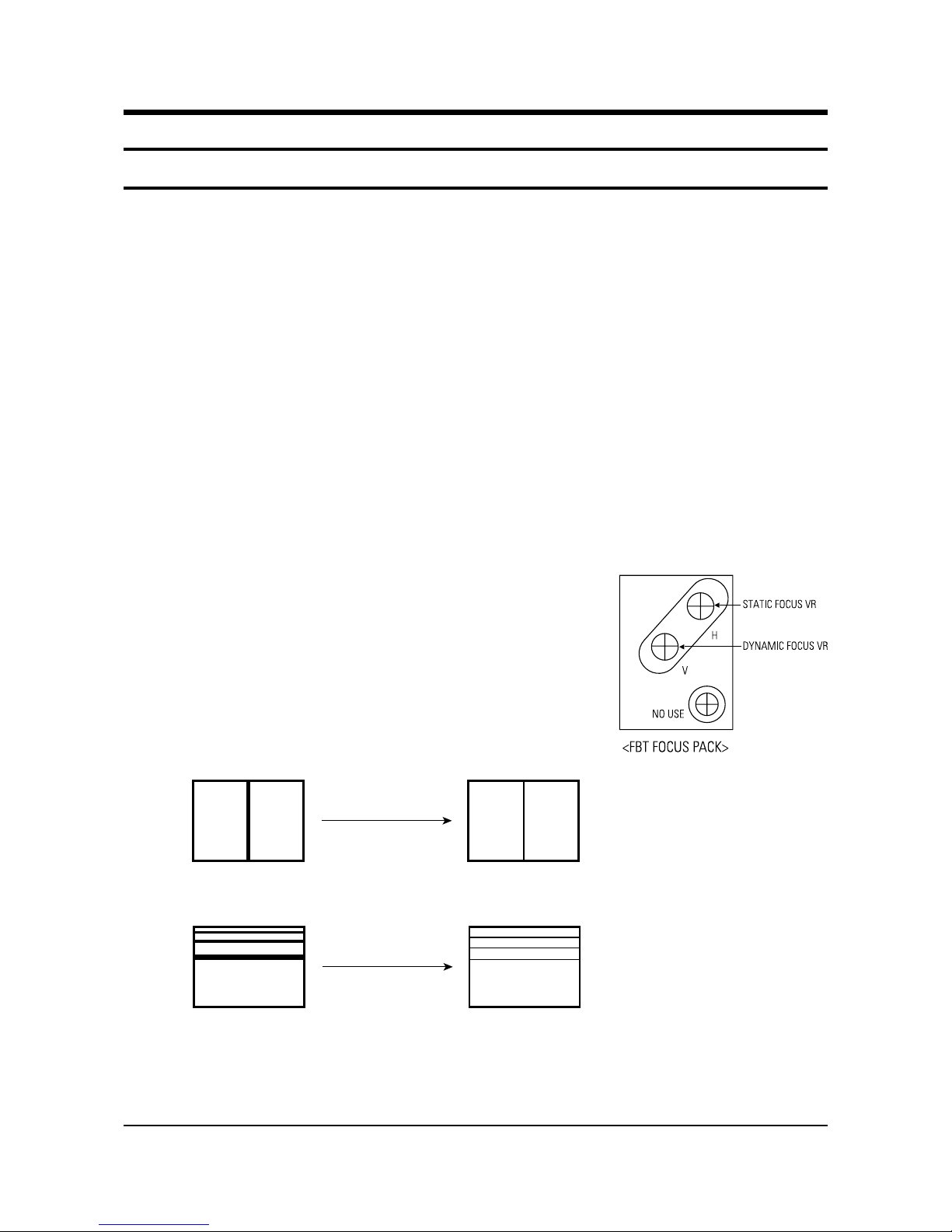
1-1-2 Focus Adjustment
K55A contains a dynamic focus circuit. When CRT PCB, FBT or CRT is replaced, be sure to adjust in the
following sequence:
Dynamic Focus Adjustment
1. Input a crosshatch pattern.
2. Select “Standard” from the menu,
3. Turn the Static Focus VR clockwise to set it to its maximum.
4. Turn the Dynamic Focus VR counterclockwise to set it to its
maximum.
5. Turn the Static Focus VR counterclockwise slowly for the clearest
center vertical line.
6. Turn the Dynamic Focus VR clockwise slowly for the clearest third line.
7. Check for the FOCUS of entire screen. If necessary, re-do adjustments 3~6.
After Adjustment
1
2
3
Alignment and Adjustments
1-2 Samsung Electronics
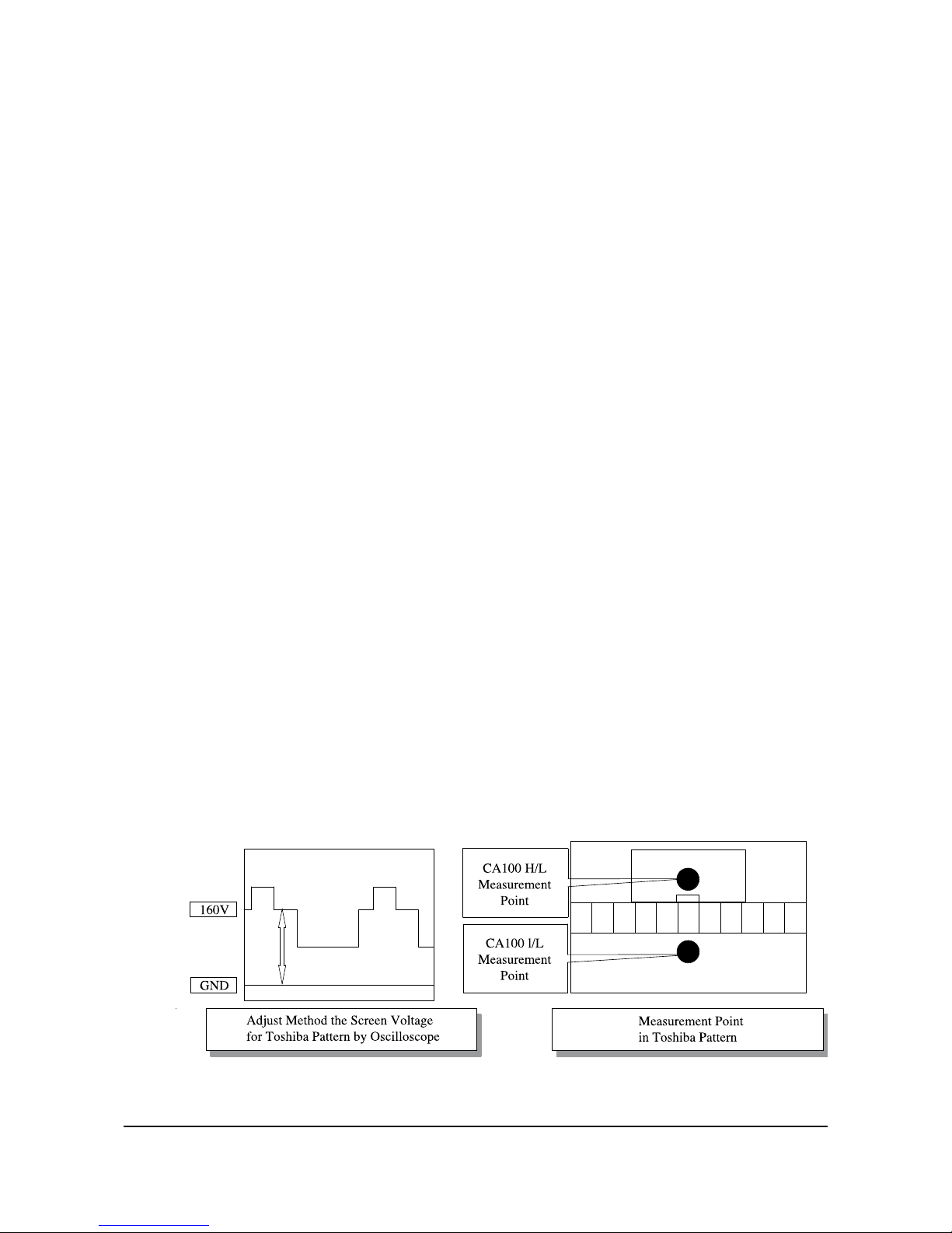
1-1-3 Screen Voltage Adjustment
1. Input a Toshiba pattern.
2. Use an oscilloscope to identify RK, BK, GK. And then adjust FBT Screen VR so that the voltage of
pedestal level doesn’t exceed 160V.
If a Toshiba pattern is not available, cancel the blue screen and input “No Signal” to AV IN so the voltage
of pedestal level doesn’t exceed 175V.
If an oscilloscope is not available, use a DC multi-meter in No Signal (black screen) to adjust RK, BK, GK
so that the highest voltage becomes 160Vp-p.
1-1-4 White Balance Adjustment
1. Warm up the TV set for at least 30 minutes.
2. Enter the Service Mode by pressing the remote control keys in the following sequence:
Power Off ➞ Display ➞ Menu ➞ Mute ➞ Power On
3. Initialize all set data.
4. Input a Toshiba pattern.
5. Using a probe(CA100), do the White Balance adjustments.
(1) Adjust Low-Light.
- Adjust Sub Brightness to set Y.
- Adjust B Cutoff to set y.
- Adjust R Cutoff to set x.
(2) Adjust High-Light.
- Adjust Sub Contrast to set Y.
- Adjust B Drive to set y.
- Adjust R Drive to set x.
(3) Check the value of Low-Light. If necessary, readjust Low-Light.
(4) Check the value of High-Light. If necessary, readjust High-Light.15

Alignment and Adjustments
Samsung Electronics 1-3
1-1-5 When adjusting Screen Voltage and White Balance
1. Screen Voltage and White Balance are related each other. Make sure both adjustments are correct.
2. Adjust Screen Voltage before White Balance Adjustments. Make sure Screen Voltage is correct.
3. If White Balance has been readjusted, re-check Screen Voltage.
4. After adjustments are complete, check the following.
- If spots appear on the screen after pressing the Power On/Off key, readjust Screen Voltage.
- If flyback lines appear on the screen, readjust Screen Voltage.

Alignment and Adjustments
1-4 Samsung Electronics
1-1-6 White Balance Adjustement.
Youngstar W/B adjusting method
DNIe "ON "
EnterFactory Mode
V ideo Adj ust 1
Set Colo r On/Off item to "0 " .
Read X1, Y1 value with W/B measuring equipment.
V ideo Adj us t1
Set Color On/Off item to "1 " .
Enter V ideo Adjust DN I e, and a d just X2 a nd Y 2 c lo s e t o X
1
an d Y1 b y changing AD9883 R Offset , Boffs e t val ue.
20, Y1 20)
At this time , th e value read by W/B measuring
equipment refers to X 2 , Y2 .
Move to V ideoAdjust 1, an d adjus t the value to X 1 3 ,
Y 1 3 by c ha nging C r , Cb Of fse t value.
A dju st X and Y value with W /B ad juste d v alu e
per area by ch an g ing R/B C u toff a nd R /B D r iv e
value.
(Spec: X1
+
+
+
+
Alignment and Adjustments
Samsung Electronics 1-5
ASSIGNMENT
RESET Control jack during E2PROM latch UP(Function:Low)SERIAL H
E2PROM only SDA LINE
E2PROM only SDA LINE
Automation and after-sales service related BUS STOP(STOP : LOW)
CXA2165 /CXA2151Q/VSP940X/BA7654F/MSP34XX/TUNER Control jack
CXA2165 /CXA2151Q/VSP940X/BA7654F/MSP34XX/TUNER Control jack
Reset when MSP34XX IC(SOUND PROCESS IC)has an error(Active : LOW)
Reset when VSP940X IC(1-chip IC)has an error
Analog GND
TTX and USA Caption Input source line(1V p-p)
Main AFT Control jack(0 ~ 3.3V)
MICOM “H-SYNC” Input, POSITIVE Input(3.3V p-p)
MICOM “V-SYNC” Input, POSITIVE Input(3.3V p-p)
OPEN
TV/VIDEO switching control jack
Function : LOW
Remote Control Input Jack
STAND BY : Hight, OFF : LOW
TIME ON : H TIME OFF : L
DEGAUSSIGN COIL CONTROL:Based on standard specifications
H : IN1, L : IN2(BA7657F) PIN(#16) Control jack
Reset active : HIGH
Crystal oscillation input jack
1-2 MICOM PORT
PIN
1
2
3
4
5
6
7
8
9
10
11
12
13
14
15
16
17
18
19
20
21
22
23
24
25
26
27
28
29
30
33
34
35
FUNCTION
W-PORT
ROM SDA
ROM SCL
BUS-STOP
MAIN SDA
MAIN SCL
S-RESET
V-RESET
VDD 2.5V
GND
VDD3.3V
CVBS IN
VDD2.5V
GND
AFT
SC1-ID
SC2-ID
KEY-1
H-SYNC
V-SYNC
KEY-3
KEY-2
X-RAY
IR-IN
STD-LED
TIM-LED
RELAY
SW1
GND
VDD 3.3V
RESET
X-IN
X-OUT
FIRST STATE
HIGH
SERIAL H
SERIAL H
HIGH
SERIAL H
SERIAL H
HIGH
HIGH
HIGH
HIGH
IV p-p
HIGH
HIGH
POSITIVE
POSITIVE
HIGH
HIGH
HIGH
HIGH
LOW
HIGH
HIGH
LOW
RANGE
TV MODE
0 ~ 2V
16 : 9 MODE
4.5 ~ 7V
4 : 3 MODE
9.5 ~ 12V
AV MODE
16 : 9 MODE
0 ~ 2V
MEMU
0~0.1V
VOL-
0.1~0.7V
VOL+
07~13V
CH-
1.3~1.9V
CH+
0.9~2.4V

Alignment and Adjustments
1-6 Samsung Electronics
ASSIGNMENT
OSD R-OUT Output jack (0.38V p-p), half tone : 0.9V p-p
OSD G-OUT Output jack (0.38V p-p), half tone : 0.9V p-p
OSD B-OUT Output jack (0.38V p-p), half tone : 0.9V p-p
OSD F/B-OUT Output jack (Clamped at STAND PULSE, Half Tone : LOW)
LOW : GNDHIGH : OPEN STATUS
Initially, these pins select an input source at LOW state
System (NTSC/PAL) MUST be separated
Active “LOW”
1080i control jack : 1080i (LOW), RF (Hight)
Magnetic field control
PIN
36
37
38
39
40
41
42
43
44
45
46
47
48
49
50
51
52
FUNCTION
GND
VDD 2.5V
OSD-R
OSD-G
OSD-B
CPRE
VDD 2.5V
GND
VDD 3.3V
PX, Y
PX, Y
SW3
SW2
S-MUTE
POWER
H,P-ID
TILT
FIRST STATE
HIGH
1.2V p-p
1.2V p-p
1.2V p-p
0.9V p-p
HIGH
HIGH
HIGH
HIGH
H
L
HIGH
F1
L
M
F0
M
L
fH
1.75KHz (480i/480P)
33.75KHz (1080i)
Alignment and Adjustments
Samsung Electronics 1-7
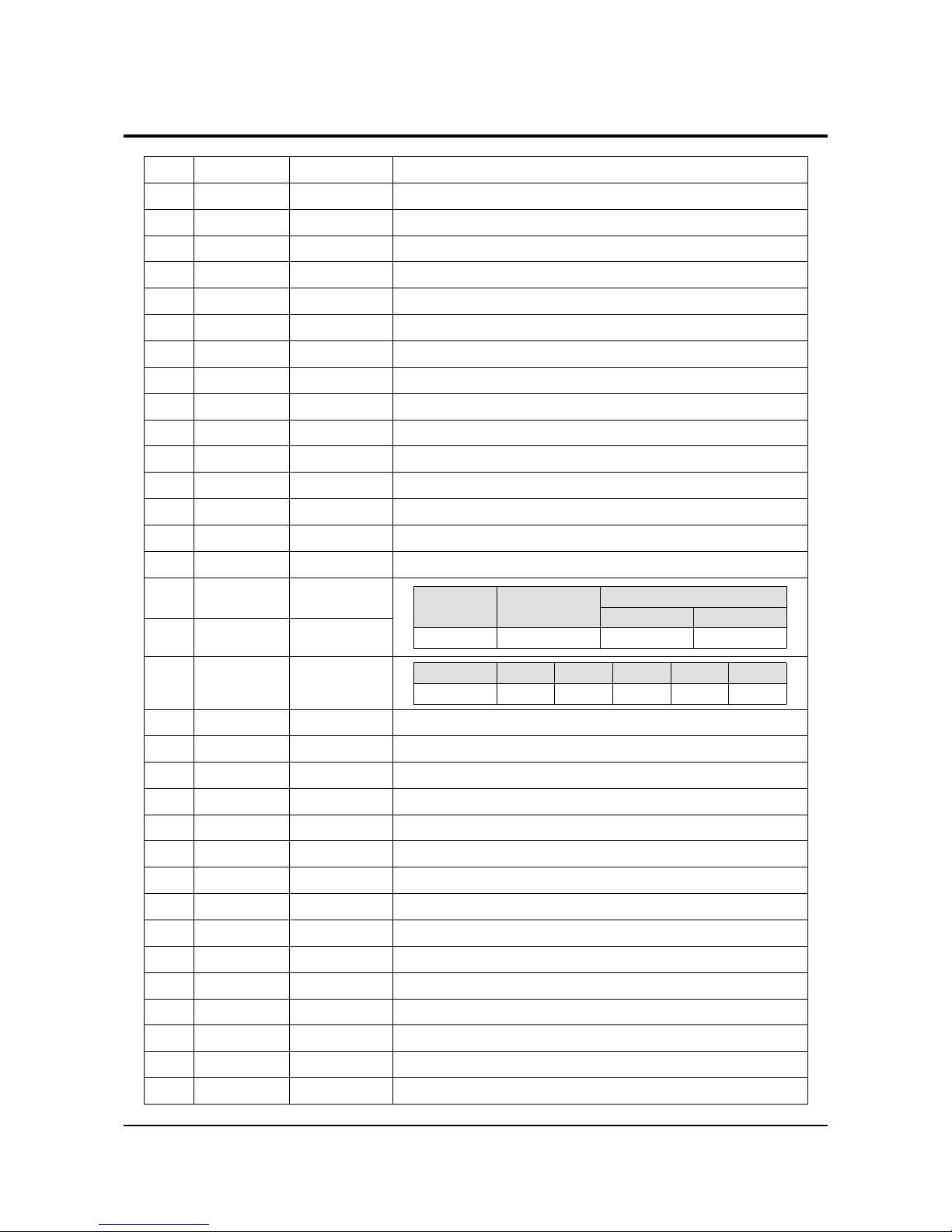
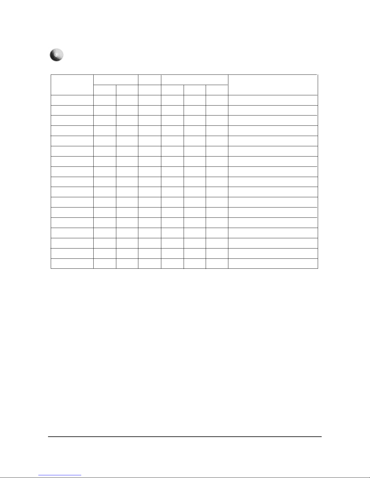
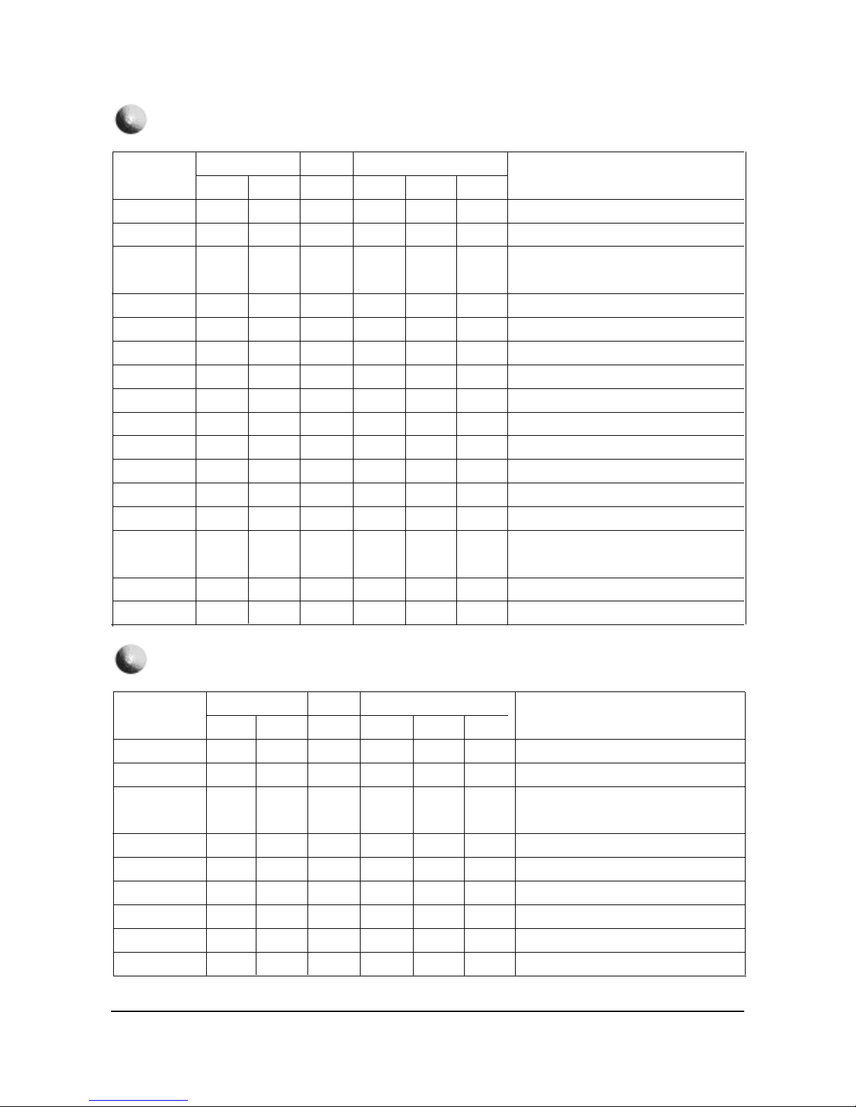
1-3 Factory Adjustment
1-3-1 Factory Adjustment values
SERVICE
Deflection
VGE offset
Video Adjust1
Video Adjust2
Video Adjust3
VGE Adujust
Video Adujust DNle
Option
YC Delay
EEPROM
Reset
1-3-2 Factory Data
ITEMS
V-AMP
V-SHIFT
H-EW
H-SHIFT
V-LIN
UP-LIN(Fix)
LOW-LIN(Fix)
V-SC(Fix)
H-PAR
UP-COR
LOW-COR
H-TRA
BOW
ANGLE
V-POSI(Fix)
29”
27
22
20
15
9
9
4
3
45
35
36
40
32
30
40
32”
30
23
16
12
9
9
3
1
23
35
34
40
32
30
40
34"
40
23
40
25
9
9
2
3
37
34
37
25
32
32
40
29"
25
24
43
13
7
9
4
5
49
36
36
31
29
27
40
32"
34
21
24
7
9
9
3
1
33
30
34
25
33
30
40
REMARK
Vertical AMP adj( Gain Control)
Vertical Position adj (DC bias adj)
Horizontal AMP adj(Gain Control)
Horizontal Position adj (DC bias adj)
Vertical Linearity adj(TOP/Bottom adj)
Vertical Linearity adj(TOP adj)
Vertical Linearity adj(Bottom adj)
Vertical S correction adj
Horizontal pin distortion adj
Horizontal pin distortion up adj
Horizontal pin distortion low adj
Horizontal Trapezium distortion adj
Vertical line slope adj(parabola)
Vertical Linearity adj(sawtooth)
V-POSITION ADJ as to CRT INCH
DEFLECTION : PAL
* CIS W/B Angular
H/L:285/285 45(+,-5)FT L/L:285/285 1.5(+,- 0.3FT)
*EUROPE W/B Angular
H/L:290/290 35FT L/L:290/290 1.5FT
CIS EUROPE
Alignment and Adjustments
1-8 Samsung Electronics
ITEMS
V-AMP
V-SHIFT
H-EW
H-SHIFT
V-LIN
UP-LIN(Fix)
LOW-LIN(Fix)
V-SC(Fix)
H-PAR
UP-COR
LOW-COR
H-TRA
BOW
ANGLE
V-POSI(Fix)
CXA2151SUB01
CXA2151SUB02
29”SDI
25
23
26
5
9
9
2
4
26
22
29
50
32
33
40
E8
61
REMARK
Vertical AMP adj( Gain Control)
Vertical Position adj (DC bias adj)
Horizontal AMP adj(Gain Control)
Horizontal Position adj (DC bias adj)
Vertical Linearity adj(TOP/Bottom adj)
Vertical Linearity adj(TOP adj)
Vertical Linearity adj(Bottom adj)
Vertical S correction adj
Horizontal pin distortion adj
Horizontal pin distortion up adj
Horizontal pin distortion low adj
Horizontal Trapezium distortion adj
Vertical line slope adj(parabola)
Vertical Linearity adj(sawtooth)
V-POSITION ADJ as to CRT INCH
Australia
32”LG
21
23
27
11
9
9
3
1
22
33
38
31
30
30
40
E8
61
29
35
22
46
18
9
9
4
1
37
17
25
55
32
31
40
E8
61
29”SDI
33
24
21
13
7
9
4
1
25
27
25
50
32
30
40
E8
61
32”LG
23
25
37
8
9
9
3
1
23
35
36
38
30
31
40
E8
61
34”TSB
28
21
44
16
9
9
3
3
28
30
38
18
33
28
40
E8
61
Southeast Asia/Hongkong
S.Asia
DEFLECTION : PAL
Alignment and Adjustments
Samsung Electronics 1-9
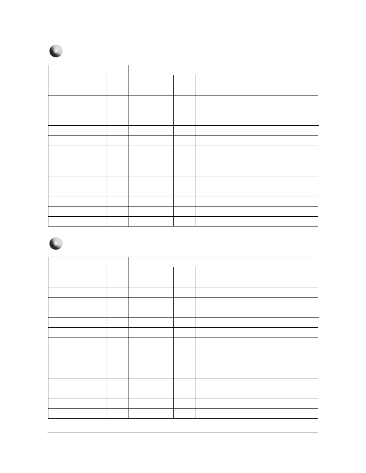
ITEMS
V-AMP
V-SHIFT
H-EW
H-SHIFT
V-LIN
UP-LIN(Fix)
LOW-LIN(Fix)
V-SC(Fix)
H-PAR
UP-COR
LOW-COR
H-TRA
BOW
ANGLE
V-POSI(Fix)
29”
-2
-3
-2
10
-4
-1
3
0
12
8
3
7
-1
-1
0
32”
3
-2
-2
11
-4
-1
3
0
1
5
-2
5
-1
0
0
34"
2
-1
-3
11
-4
1
3
0
-1
-1
-3
4
1
0
0
29"
4
-2
2
10
-4
-1
3
0
8
7
3
7
-1
-1
0
32"
2
-3
0
15
-4
-1
3
0
4
8
1
10
-1
1
0
REMARK
Vertical AMP adj( Gain Control)
Vertical Position adj (DC bias adj)
Horizontal AMP adj(Gain Control)
Horizontal Position adj (DC bias adj)
Vertical Linearity adj(TOP/Bottom adj)
Vertical Linearity adj(TOP adj)
Vertical Linearity adj(Bottom adj)
Vertical S correction adj
Horizontal pin distortion adj
Horizontal pin distortion up adj
Horizontal pin distortion low adj
Horizontal Trapezium distortion adj
Vertical line slope adj(parabola)
Vertical Linearity adj(sawtooth)
V-POSITION ADJ as to CRT INCH
DEFLECTION : NTSC
CIS EUROPE
CIS W/B Angular
H/L:285/285 50(+,-5)FT L/L:285/285 2.5(+,- 0.3FT)
Alignment and Adjustments
1-10 Samsung Electronics
29”
0
-2
-2
8
-4
-1
2
0
3
6
-1
3
0
0
0
E8
61
Southeast Asia/Hongkong
Australia
32”
-6
-3
1
9
-4
-1
3
0
5
10
-2
16
0
0
0
E8
61
29
0
-2
-2
8
-4
-1
2
0
-8
1
5
27
0
0
0
E8
61
29”
1
-2
-1
7
-4
-1
2
0
0
-10
-6
4
1
0
0
E8
61
32”
1
4
-1
11
-4
-1
3
0
-2
1
-4
-1
2
2
2
E8
61
34”
3
-2
0
10
-4
-1
3
0
8
7
3
7
-1
-1
0
E8
61
ITEMS
V-AMP
V-SHIFT
H-EW
H-SHIFT
V-LIN
UP-LIN(Fix)
LOW-LIN(Fix)
V-SC(Fix)
H-PAR
UP-COR
LOW-COR
H-TRA
BOW
ANGLE
V-POSI(Fix)
CXA2151SUB01
CXA2151SUB02
REMARK
Vertical AMP adj( Gain Control)
Vertical Position adj (DC bias adj)
Horizontal AMP adj(Gain Control)
Horizontal Position adj (DC bias adj)
Vertical Linearity adj(TOP/Bottom adj)
Vertical Linearity adj(TOP adj)
Vertical Linearity adj(Bottom adj)
Vertical S correction adj
Horizontal pin distortion adj
Horizontal pin distortion up adj
Horizontal pin distortion low adj
Horizontal Trapezium distortion adj
Vertical line slope adj(parabola)
Vertical Linearity adj(sawtooth)
V-POSITION ADJ as to CRT INCH
S.Asia
DEFLECTION : NTSC
Alignment and Adjustments
Samsung Electronics 1-11
29”
-3
1
2
8
0
-1
-3
2
6
4
3
-1
2
2
0
E8
61
Southeast Asia/Hongkong
Australia
32”
-11
0
5
10
0
0
0
0
-1
1
-1
10
1
0
0
E8
61
29
0
-2
-2
8
-4
-1
2
0
-8
1
5
27
0
0
0
E8
61
29”
-1
2
3
8
-1
0
0
0
-2
0
0
5
1
0
0
E8
61
32”
-3
0
2
9
0
0
0
0
0
1
0
6
1
-1
0
E8
61
34”
-2
2
2
-16
0
0
0
0
-4
0
-2
8
-2
0
0
E8
61
ITEMS
V-AMP
V-SHIFT
H-EW
H-SHIFT
V-LIN
UP-LIN(Fix)
LOW-LIN(Fix)
V-SC(Fix)
H-PAR
UP-COR
LOW-COR
H-TRA
BOW
ANGLE
V-POSI(Fix)
CXA2151SUB01
CXA2151SUB02
REMARK
Vertical AMP adj( Gain Control)
Vertical Position adj (DC bias adj)
Horizontal AMP adj(Gain Control)
Horizontal Position adj (DC bias adj)
Vertical Linearity adj(TOP/Bottom adj)
Vertical Linearity adj(TOP adj)
Vertical Linearity adj(Bottom adj)
Vertical S correction adj
Horizontal pin distortion adj
Horizontal pin distortion up adj
Horizontal pin distortion low adj
Horizontal Trapezium distortion adj
Vertical line slope adj(parabola)
Vertical Linearity adj(sawtooth)
V-POSITION ADJ as to CRT INCH
S.Asia
DEFLECTION : 480P OFFSET

Alignment and Adjustments
1-12 Samsung Electronics
29”
-4
-1
-6
-7
-1
0
-1
0
-4
0
3
-10
0
1
0
C0
61
Southeast Asia/Hongkong
Australia
32”
-16
-1
-6
7
0
-1
-2
-1
2
7
-3
16
0
0
0
C0
61
29
-20
0
14
6
0
0
-1
1
-5
-7
-3
-7
0
1
0
C4
61
29”
-11
-2
13
4
1
0
-1
1
-5
-18
-5
1
0
0
0
C4
61
32”
-20
-2
15
6
0
-1
-2
-1
1
0
-1
0
0
0
0
C4
61
34”
-11
-1
10
6
0
-1
-1
-1
-4
-4
-8
14
-2
0
0
C4
61
ITEMS
V-AMP
V-SHIFT
H-EW
H-SHIFT
V-LIN
UP-LIN(Fix)
LOW-LIN(Fix)
V-SC(Fix)
H-PAR
UP-COR
LOW-COR
H-TRA
BOW
ANGLE
V-POSI(Fix)
CXA2151SUB01
CXA2151SUB02
REMARK
Vertical AMP adj( Gain Control)
Vertical Position adj (DC bias adj)
Horizontal AMP adj(Gain Control)
Horizontal Position adj (DC bias adj)
Vertical Linearity adj(TOP/Bottom adj)
Vertical Linearity adj(TOP adj)
Vertical Linearity adj(Bottom adj)
Vertical S correction adj
Horizontal pin distortion adj
Horizontal pin distortion up adj
Horizontal pin distortion low adj
Horizontal Trapezium distortion adj
Vertical line slope adj(parabola)
Vertical Linearity adj(sawtooth)
V-POSITION ADJ as to CRT INCH
S.Asia
DEFLECTION : 1080i OFFSET

Alignment and Adjustments
Samsung Electronics 1-13
29”
24
22
30
25
7
9
4
3
38
25
29
53
32
32
40
68
61
Southeast Asia/Hongkong
Australia
32”
24
22
30
25
7
9
4
3
38
25
29
53
32
32
40
68
61
29
24
22
30
25
7
9
4
3
38
25
29
53
32
32
40
68
61
29”
24
22
30
25
7
9
4
3
38
25
29
53
32
32
40
68
61
32”
24
22
30
25
7
9
4
3
38
25
29
53
32
32
40
68
61
34”
24
22
30
25
7
9
4
3
38
25
29
53
32
32
40
68
61
ITEMS
V-AMP
V-SHIFT
H-EW
H-SHIFT
V-LIN
UP-LIN(Fix)
LOW-LIN(Fix)
V-SC(Fix)
H-PAR
UP-COR
LOW-COR
H-TRA
BOW
ANGLE
V-POSI(Fix)
CXA2151SUB01
CXA2151SUB02
REMARK
Vertical AMP adj( Gain Control)
Vertical Position adj (DC bias adj)
Horizontal AMP adj(Gain Control)
Horizontal Position adj (DC bias adj)
Vertical Linearity adj(TOP/Bottom adj)
Vertical Linearity adj(TOP adj)
Vertical Linearity adj(Bottom adj)
Vertical S correction adj
Horizontal pin distortion adj
Horizontal pin distortion up adj
Horizontal pin distortion low adj
Horizontal Trapezium distortion adj
Vertical line slope adj(parabola)
Vertical Linearity adj(sawtooth)
V-POSITION ADJ as to CRT INCH
S.Asia
DEFLECTION : VGA OFFSET
Alignment and Adjustments
1-14 Samsung Electronics
ITEMS
R-Cutoff
G-Cutoff
B-Cutoff
Color on/off
CR offset
CB offset
R-Drive
G-Drive
B-Drive
Sub-Bright
Sub-Contrast
Sub-Color
Sub-Tint
CTI-Level
COL AXIS
LTI-Level
VSU
Merody Volume
29"
39
30
33
1
32
32
30
30
34
31
7
15
28
1
1
1
2
7
32"
31
32
35
1
32
32
32
25
30
26
7
15
28
1
1
1
2
7
34"
32
34
32
1
37
32
41
32
33
36
6
15
28
1
1
1
3
7
29"
41
32
28
1
32
32
37
32
32
32
7
12
28
1
1
1
2
7
32"
37
32
43
1
30
30
35
25
30
33
10
12
28
1
1
1
2
7
REMARK
R-cutoff control adj
G-cutoff control adj
B-cutoff control adj
Initial Value : "0"--> 1
DC-offset canceling
DC-offset canceling
R-Drive control adj
G-Drive control adj
B-Drive control adj
Sub-Bright control
Sub-Contrast control
color gain control(PAL SETTING AGAIN)
HUE control
Chrominance Transient Improvement
color detection axis setting(NTSC/USA)
Luminance Transient Improvement
vertical osd position
Volume gain control
Video Adjust 1
CIS EUROPE
Alignment and Adjustments
Samsung Electronics 1-15
29”SDI
31
25
41
1
35
34
35
32
37
29
7
15
28
1
1
1
3
7
Australia
32”LG
31
25
43
1
32
32
37
32
43
33
7
15
28
1
1
1
3
7
29”SDI
41
32
28
1
32
32
37
32
32
32
7
15
28
1
1
1
3
7
29”SDI
41
32
28
1
32
32
37
32
32
32
7
15
28
1
1
1
3
7
32”LG
31
32
43
1
32
32
37
32
43
33
7
15
28
1
1
1
3
7
34”TSB
34
25
35
1
32
32
43
32
36
34
7
15
28
1
1
1
3
7
Southeast Asia/Hongkong
S.Asia
ITEMS
R-Cutoff
G-Cutoff
B-Cutoff
Color on/off
CR offset
CB offset
R-Drive
G-Drive
B-Drive
Sub-Bright
Sub-Contrast
Sub-Color
Sub-Tint
CTI-Level
COL AXIS
LTI-Level
VSU
Merody Volume
REMARK
R-cutoff control adj
G-cutoff control adj
B-cutoff control adj
Initial Value : "0"--> 1
DC-offset canceling
DC-offset canceling
R-Drive control adj
G-Drive control adj
B-Drive control adj
Sub-Bright control
Sub-Contrast control
color gain control(PAL SETTING AGAIN)
HUE control
Chrominance Transient Improvement
color detection axis setting(NTSC/USA)
Luminance Transient Improvement
vertical osd position
Volume gain control
Video Adjust 1
Alignment and Adjustments
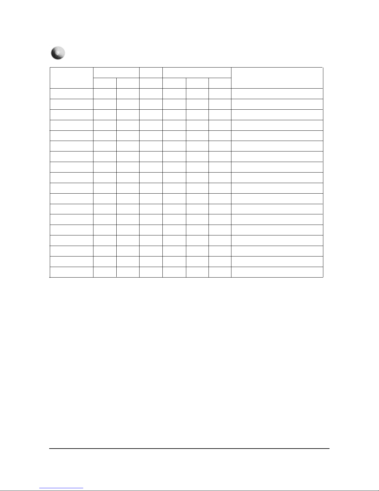
1-16 Samsung Electronics
ITEMS
ABL Mode
Gamma
DPIC Level
DC Trans
ABL-TH
VM-Level
VM-Coring
VM-f0
VM-Limit
VM-Delay
SHP CD
SHP f0
SHP f1&p/o
AKB Time
Bandpass 9407
Highpass 9407
29"
3
2
2
2
14
1
2
2
2
3
1
0
8
13
16
23
32"
3
2
2
2
15
1
2
2
2
3
1
0
8
13
16
23
34"
3
2
2
2
14
1
2
2
2
3
1
0
8
13
16
23
29"
3
2
3
3
14
1
2
2
2
3
1
0
8
13
20h
23h
32"
3
2
3
3
14
1
2
2
2
3
1
0
8
13
20h
23h
REMARK
picture/bright ABL gain control(PAL SETTING AGAIN)
RGB output correction control(PAL SETTING AGAIN)
Dynamic picture black expansion control
(PAL SETTING AGAIN)
Y-System DC transmission ratio(PAL SETTING AGAIN)
Threshold voltage adj ABL-IN(PAL SETTING AGAIN)
VM-OUT Level control
VM-OUT coring control
VM-f0 control
VM-Limit level control
VM-OUT phase control(reference to R-OUT)
Sharpness gain control(color satuation)
Sharpness f0 control (3Mhz)
Sharpness gain control(PAL SETTING AGAIN)
AKB Bch reference pulse time control
(PAL SETTING AGAIN)
VSP9407 Band/High pass filter(Peaking)
VSP9407 High pass filter
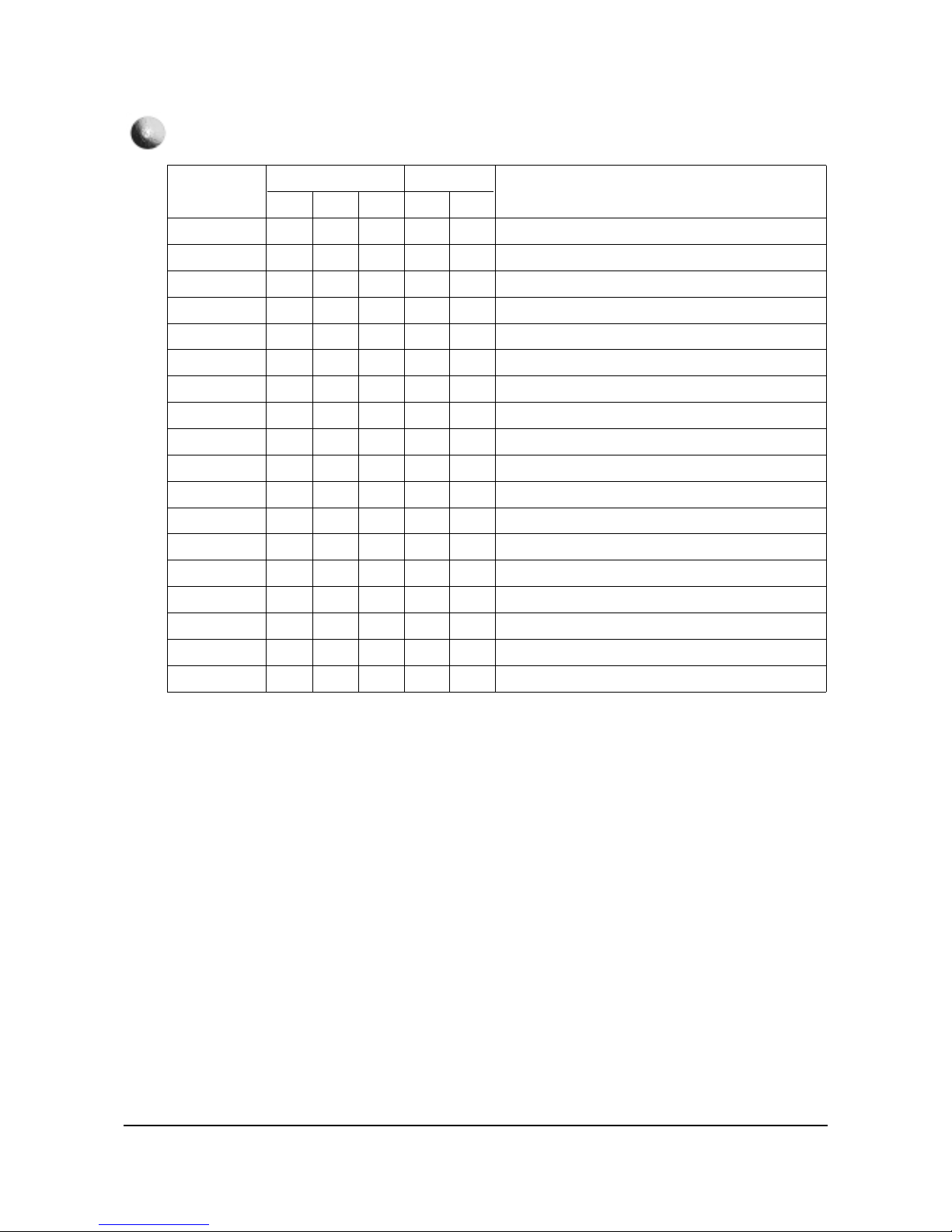
Video Adjust 2
CIS EUROPE
ITEMS
H comp
V comp
PIN comp
AFC comp
Sync phase
NR Off Value
Sync phase(VGA)
29"
7
4
2
0
0
6
0
32"
8
5
2
0
0
6
0
34"
4
4
7
0
0
6
0
29"
7
4
2
0
0
6
0
32"
7
4
2
0
0
6
0
REMARK
H-EHT compensation setting(PAL SETTING AGAIN)
V-EHT compensation setting(PAL SETTING AGAIN)
PIN-EHT compensation setting
(PAL SETTING AGAIN)
AFC-EHT compensation
WHEN USED 74HC123
Not used
Sync phase control of VGE mode
Video Adjust 3
CIS EUROPE
Alignment and Adjustments
Samsung Electronics 1-17
Australia
Southeast Asia/Hongkong
S.Asia
Video Adjust 2
Video Adjust 3
ITEMS
ABL Mode
Gamma
DPIC Level
DC Trans
ABL-TH
VM-Level
VM-Coring
VM-f0
VM-Limit
VM-Delay
SHP CD
SHP f0
SHP f1&p/o
AKB Time
Bandpass 9407
Highpass 9407
REMARK
picture/bright ABL gain control(PAL SETTING AGAIN)
RGB output correction control(PAL SETTING AGAIN)
Dynamic picture black expansion control
(PAL SETTING AGAIN)
Y-System DC transmission ratio(PAL SETTING AGAIN)
Threshold voltage adj ABL-IN(PAL SETTING AGAIN)
VM-OUT Level control
VM-OUT coring control
VM-f0 control
VM-Limit level control
VM-OUT phase control(reference to R-OUT)
Sharpness gain control(color satuation)
Sharpness f0 control (3Mhz)
Sharpness gain control(PAL SETTING AGAIN)
AKB Bch reference pulse time control
(PAL SETTING AGAIN)
VSP9407 Band/High pass filter(Peaking)
VSP9407 High pass filter
29"SDI
3
2
3
2
14
1
2
2
2
3
1
0
8
13
16
42
32”LG
3
2
3
2
15
1
2
2
2
3
1
0
8
13
16
42
29"SDI
3
2
3
2
14
1
2
2
2
3
1
0
8
13
16
42
29"SDI
3
2
3
2
14
1
2
2
2
3
1
0
8
13
16
42
32"LG
3
2
3
2
15
1
2
2
2
3
1
0
8
13
16
42
35”TSB
3
2
3
2
14
1
2
2
2
3
1
0
8
13
16
42
Australia
Southeast Asia/Hongkong
S.Asia
29"SDI
4
2
2
0
0
6
0
0
1
32”LG
4
2
2
0
0
6
0
0
1
29"SDI
4
2
2
0
0
6
0
0
1
29"SDI
4
2
2
0
0
6
0
0
1
32"LG
4
2
2
0
0
6
0
0
1
35”TSB
4
4
7
0
0
6
0
0
1
ITEMS
H comp
V comp
PIN comp
AFC comp
Sync phase
NR Off Value
Sync phase(480)
Sync phase(1080)
Sync phase(VGA)
REMARK
H-EHT compensation setting(PAL SETTING AGAIN)
V-EHT compensation setting(PAL SETTING AGAIN)
PIN-EHT compensation setting
(PAL SETTING AGAIN)
AFC-EHT compensation
WHEN USED 74HC123
Not used
Sync phase control of VGE mode
Alignment and Adjustments
1-18 Samsung Electronics
Australia
Southeast Asia/Hongkong
S.Asia
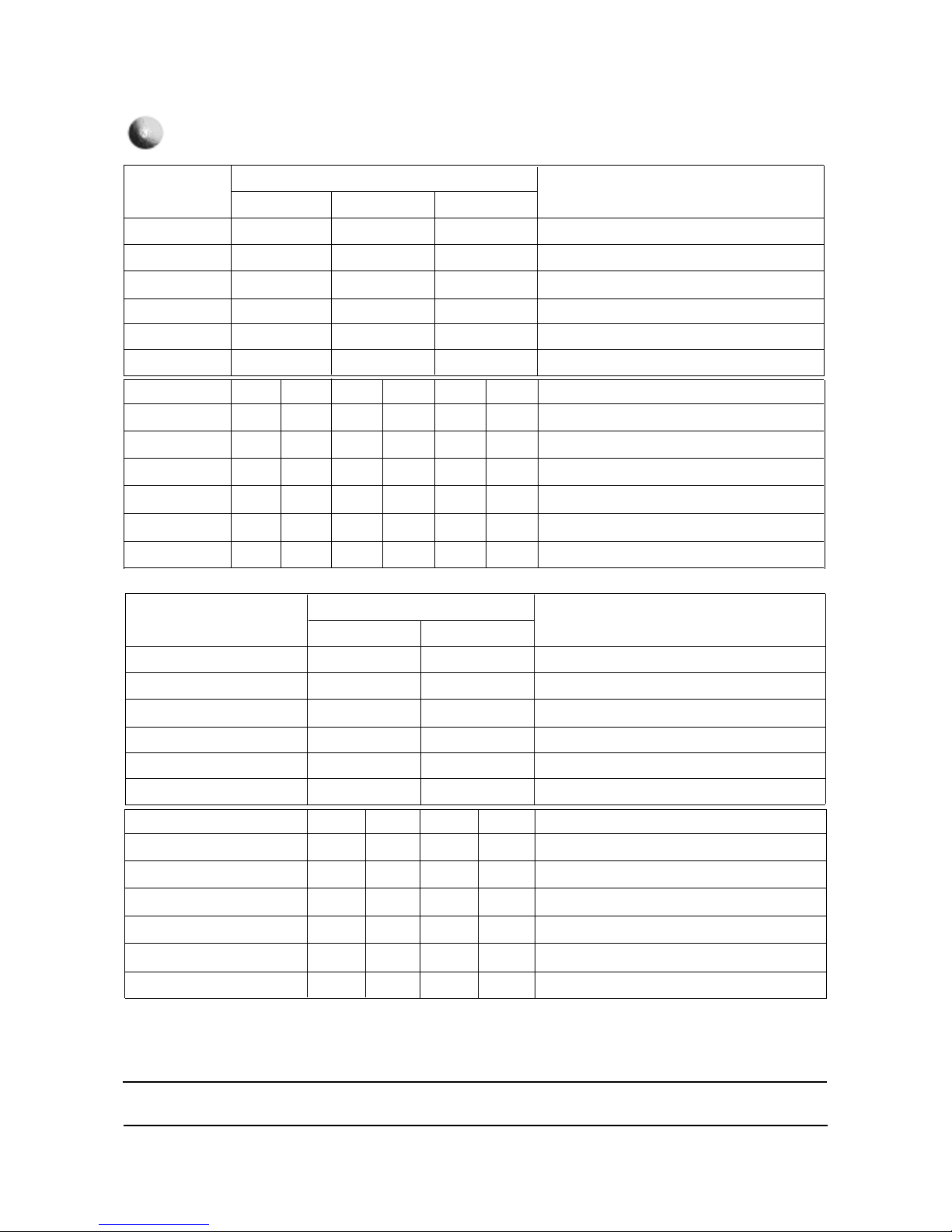
VGA Adjust
ITEMS
Sub-Bright
Sub-Contrast
Sub-Color
Sub-Tint
COL AXIS
LTI-Level
VM-Level
VM-Coring
VM-f0
VM-Limit
VM-Delay
SHP CD
SHP f0
SHP f1&p/o
REMARK
29"SDI
20
7
15
28
1
1
1
2
2
2
3
1
1
8
32”LG
20
7
15
28
1
1
1
2
2
2
3
1
1
8
29"SDI
20
7
15
28
1
1
1
2
2
2
3
1
1
8
29"SDI
20
7
15
28
1
1
1
2
2
2
3
1
1
8
32"LG
20
7
15
28
1
1
1
2
2
2
3
1
1
8
35”TSB
20
7
15
28
1
1
1
2
2
2
3
1
1
8
Australia
Southeast Asia/Hongkong
S.Asia
ITEMS
Sub-Bright
Sub-Contrast
Sub-Color
Sub-Tint
COL AXIS
LTI-Level
VM-Level
VM-Coring
VM-f0
VM-Limit
VM-Delay
SHP CD
SHP f0
SHP f1&p/o
REMARK
29"SDI
19
7
15
28
1
1
1
2
2
2
3
1
1
8
32”LG
19
7
15
28
1
2
1
2
2
2
3
1
0
8
29"SDI
19
7
15
28
1
1
1
2
2
2
3
1
1
8
29"SDI
19
7
15
28
1
1
1
2
2
2
3
1
1
8
32"LG
19
7
15
28
1
2
1
2
2
2
3
1
0
8
35”TSB
19
7
15
28
1
2
1
2
2
2
3
1
0
8
DTV Adjust (480)

Alignment and Adjustments
Samsung Electronics 1-19
Australia
Southeast Asia/Hongkong
S.Asia
ITEMS
Sub-Bright
Sub-Contrast
Sub-Color
Sub-Tint
COL AXIS
LTI-Level
VM-Level
VM-Coring
VM-f0
VM-Limit
VM-Delay
SHP CD
SHP f0
SHP f1&p/o
REMARK
29"SDI
38
7
15
28
1
1
1
2
2
2
3
1
1
8
32”LG
38
7
15
28
1
2
1
2
2
2
3
1
1
8
29"SDI
38
7
15
28
1
1
1
2
2
2
3
1
1
8
29"SDI
38
7
15
28
1
1
1
2
2
2
3
1
1
8
32"LG
38
7
15
28
1
2
1
2
2
2
3
1
1
8
35”TSB
38
7
15
28
1
2
1
2
2
2
3
1
1
8
DTV Adjust (1080)
Alignment and Adjustments
1-20 Samsung Electronics
ITEMS
AD9883 R Gain
AD9883 G Gain
AD9883 B Gain
AD9883 R Offset
AD9883 G Offset
AD9883 B Offset
DNIe On/Off/Demo
SNI OVG H
SNI OVG V
SNI HPF
SNI COR
SNI CLIP
SNI LPF/DIF
32"
185
185
185
60
64
60
29"
185
185
185
60
64
60
On/Off
20
8
30
3
30
9
Demo
20
10
30
3
30
9
On/Off
20
8
30
3
30
9
Demo
20
10
30
3
30
9
On/Off
20
8
30
3
30
9
Demo
20
10
30
3
30
9
34"
185
185
185
60
64
60
REMARK
H-EHT compensation setting(PAL SETTING AGAIN)
V-EHT compensation setting(PAL SETTING AGAIN)
PIN-EHT compensation setting
AFC-EHT compensation
WHEN USED 74HC123
Not used
SNI Horizontal overgain control
SNI Vertical overgain control
SNI High pass filtering
SNI Corring control
SNI Clipping control
SNI LPF/DIF control
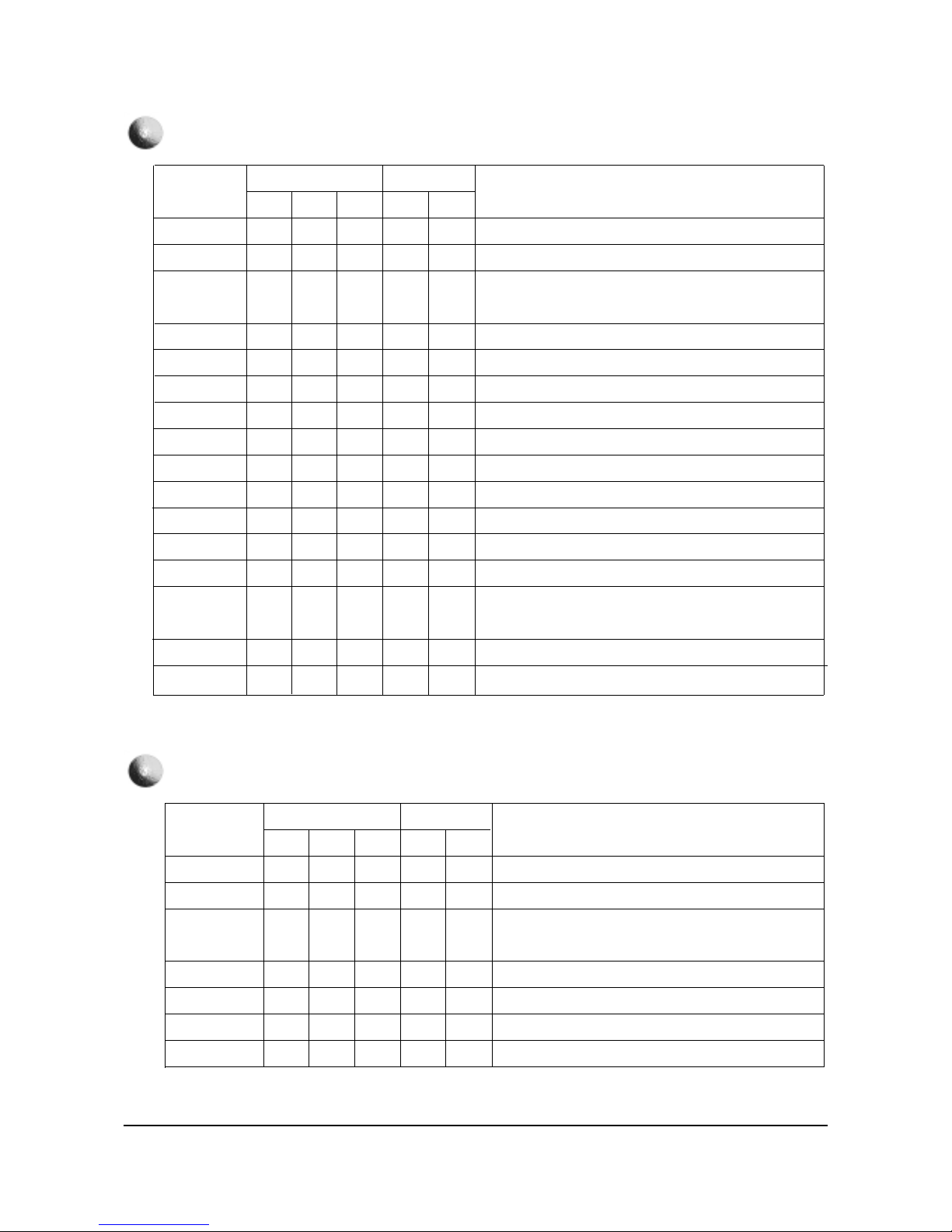
VIDEO ADUJUST DNIe
CIS
ITEMS
AD9883 R Gain
AD9883 G Gain
AD9883 B Gain
AD9883 R Offset
AD9883 G Offset
AD9883 B Offset
DNIe On/Off/Demo
SNI OVG H
SNI OVG V
SNI HPF
SNI COR
SNI CLIP
SNI LPF/DIF
32"
185
185
185
60
64
60
29"
185
185
185
60
64
60
On/Off
20
5
25
3
30
9
Demo
20
8
30
3
30
9
On/Off
20
5
25
3
30
9
Demo
20
8
30
3
30
9
REMARK
H-EHT compensation setting(PAL SETTING AGAIN)
V-EHT compensation setting(PAL SETTING AGAIN)
PIN-EHT compensation setting
AFC-EHT compensation
WHEN USED 74HC123
Not used
SNI Horizontal overgain control
SNI Vertical overgain control
SNI High pass filtering
SNI Corring control
SNI Clipping control
SNI LPF/DIF control
EUROPE
DNIe On/Off/Demo How to set up :
Please set up the DNIe:On/Off on the OSD screen and than change.
 Loading...