

Samsung CW29M066V7XXEC Service Manual
COLOR TELEVISION RECEIVER
Chassis : S61B(P)_Negotiator-2
Model : CW29M066V7XXEC
COLOR TELEVISION RECEIVER FEATURES
■■
SRS, WOW(NICAM/STEREO)
■
Simple 100Hz SCAN
■
■
2SCARTS / HALF TONE OSD
■
10Page TTX
SERVICE
Manual
CW-29M066V

This Service Manual is a property of Samsung Electronics Co.,Ltd.
Any unauthorized use of Manual can be punished under applicable
International and/or domestic law.
© Samsung Electronics Co., Ltd. Sep. 2005
Printed in Korea
AA82-02990A
ELECTRONICS

Table of Contents
Chapter 1 Precaution
■ 1-1 Safety Precautions . . . . . . . . . . . . . . . . . . . . . . . . . . . . . . . . . . . . . . . . . . . . . . . . . . . . . . . . . . . 1-1
■ 1-2 Servicing Precautions . . . . . . . . . . . . . . . . . . . . . . . . . . . . . . . . . . . . . . . . . . . . . . . . . . . . . . . . 1-3
■ 1-3 Static Electricity Precautions . . . . . . . . . . . . . . . . . . . . . . . . . . . . . . . . . . . . . . . . . . . . . . . . . . . 1-4
■ 1-4 Installation Precautions . . . . . . . . . . . . . . . . . . . . . . . . . . . . . . . . . . . . . . . . . . . . . . . . . . . . . . . 1-5
Chapter 2 Product Specification
■ 2-1 Product Features . . . . . . . . . . . . . . . . . . . . . . . . . . . . . . . . . . . . . . . . . . . . . . . . . . . . . . . . . . . . 2-1
■ 2-2 Key Features . . . . . . . . . . . . . . . . . . . . . . . . . . . . . . . . . . . . . . . . . . . . . . . . . . . . . . . . . . . . . . . 2-2
■ 2-3 Specifications Analysis . . . . . . . . . . . . . . . . . . . . . . . . . . . . . . . . . . . . . . . . . . . . . . . . . . . . . . . . 2-4
■ 2-4 Accessories . . . . . . . . . . . . . . . . . . . . . . . . . . . . . . . . . . . . . . . . . . . . . . . . . . . . . . . . . . . . . . . . 2-5
Chapter 3 Alignment & Adjustment
■ 3-1 Service Instruction . . . . . . . . . . . . . . . . . . . . . . . . . . . . . . . . . . . . . . . . . . . . . . . . . . . . . . . . . . . 3-1
■ 3-2 How to Access Service Mode . . . . . . . . . . . . . . . . . . . . . . . . . . . . . . . . . . . . . . . . . . . . . . . . . . . 3-2
■ 3-3 Factory Data . . . . . . . . . . . . . . . . . . . . . . . . . . . . . . . . . . . . . . . . . . . . . . . . . . . . . . . . . . . . . . . . 3-3
■ 3-4 Service Adjustment . . . . . . . . . . . . . . . . . . . . . . . . . . . . . . . . . . . . . . . . . . . . . . . . . . . . . . . . . . 3-21
■ 3-5 Replacements & Calibration . . . . . . . . . . . . . . . . . . . . . . . . . . . . . . . . . . . . . . . . . . . . . . . . . . . . 3-23
Chapter 4 Exploded View & Part List
■ 4-1 CW29M066V7XXEC . . . . . . . . . . . . . . . . . . . . . . . . . . . . . . . . . . . . . . . . . . . . . . . . . . . . . . . . . 4-1
Chapter 5 Electrical Part List
■ 5-1 CW29M066V7XXEC . . . . . . . . . . . . . . . . . . . . . . . . . . . . . . . . . . . . . . . . . . . . . . . . . . . . . . . . . 5-1
Chapter 6 Troubleshooting
■ 6-1 Checkpoints by Error Mode . . . . . . . . . . . . . . . . . . . . . . . . . . . . . . . . . . . . . . . . . . . . . . . . . . . . 6-1
■ 6-2 Troubleshooting Procedures by Error Modes . . . . . . . . . . . . . . . . . . . . . . . . . . . . . . . . . . . . . . . 6-4
■ 6-3 Troubleshooting Procedures by ASS'Y . . . . . . . . . . . . . . . . . . . . . . . . . . . . . . . . . . . . . . . . . . . 6-5
■ 6-4 Troubleshooting by Blocks . . . . . . . . . . . . . . . . . . . . . . . . . . . . . . . . . . . . . . . . . . . . . . . . . . . . . 6-9
Chapter 7 Block Diagram
■ 7-1 Overall Block Diagram . . . . . . . . . . . . . . . . . . . . . . . . . . . . . . . . . . . . . . . . . . . . . . . . . . . . . . . . 7-1
■ 7-2 Partial Block Diagram . . . . . . . . . . . . . . . . . . . . . . . . . . . . . . . . . . . . . . . . . . . . . . . . . . . . . . . . . 7-2
■ 7-3 Power Block Diagram . . . . . . . . . . . . . . . . . . . . . . . . . . . . . . . . . . . . . . . . . . . . . . . . . . . . . . . . . 7-5

Chapter 8 Wiring Diagram
■ 8-1 Overall Wiring . . . . . . . . . . . . . . . . . . . . . . . . . . . . . . . . . . . . . . . . . . . . . . . . . . . . . . . . . . . . . . . 8-1
■ 8-2 Pin Connection . . . . . . . . . . . . . . . . . . . . . . . . . . . . . . . . . . . . . . . . . . . . . . . . . . . . . . . . . . . . . . 8-2
Chapter 9 PCB Diagram
■ 9-1 Main Board . . . . . . . . . . . . . . . . . . . . . . . . . . . . . . . . . . . . . . . . . . . . . . . . . . . . . . . . . . . . . . . . . 9-1
■ 9-2 F/BOX Module . . . . . . . . . . . . . . . . . . . . . . . . . . . . . . . . . . . . . . . . . . . . . . . . . . . . . . . . . . . . . . 9-3
■ 9-3 CRT Board . . . . . . . . . . . . . . . . . . . . . . . . . . . . . . . . . . . . . . . . . . . . . . . . . . . . . . . . . . . . . . . . . 9-5
Chapter 10 Schematic Diagram
■ 10-1 CRT DRIVE . . . . . . . . . . . . . . . . . . . . . . . . . . . . . . . . . . . . . . . . . . . . . . . . . . . . . . . . . . . . . . . 10-1
■ 10-2 MICOM . . . . . . . . . . . . . . . . . . . . . . . . . . . . . . . . . . . . . . . . . . . . . . . . . . . . . . . . . . . . . . . . . . . 10-2
■ 10-3 Power & Deflection . . . . . . . . . . . . . . . . . . . . . . . . . . . . . . . . . . . . . . . . . . . . . . . . . . . . . . . . . . 10-3
■ 10-4 Sound & Scart . . . . . . . . . . . . . . . . . . . . . . . . . . . . . . . . . . . . . . . . . . . . . . . . . . . . . . . . . . . . . 10-4
■ 10-5 Sound processor . . . . . . . . . . . . . . . . . . . . . . . . . . . . . . . . . . . . . . . . . . . . . . . . . . . . . . . . . . . 10-5
■ 10-6 Tuner & F_box Interface . . . . . . . . . . . . . . . . . . . . . . . . . . . . . . . . . . . . . . . . . . . . . . . . . . . . . 10-6
■ 10-7 Video processor . . . . . . . . . . . . . . . . . . . . . . . . . . . . . . . . . . . . . . . . . . . . . . . . . . . . . . . . . . . . 10-7
■ 10-8 Video SW & AD . . . . . . . . . . . . . . . . . . . . . . . . . . . . . . . . . . . . . . . . . . . . . . . . . . . . . . . . . . . . 10-8
Chapter 11 Operation Instruction & Installation
■ 11-1 Product Features and Functions . . . . . . . . . . . . . . . . . . . . . . . . . . . . . . . . . . . . . . . . . . . . . . . 11-1
Chapter 12 Disassembly & Reassembly
■ 12-1 Overhaul Disassembly & Reassembly . . . . . . . . . . . . . . . . . . . . . . . . . . . . . . . . . . . . . . . . . . . 12-1
Chapter 13 Circuit Description
■ 13-1 Overall Block Description . . . . . . . . . . . . . . . . . . . . . . . . . . . . . . . . . . . . . . . . . . . . . . . . . . . . . 13-1
■ 13-2 IC Line up . . . . . . . . . . . . . . . . . . . . . . . . . . . . . . . . . . . . . . . . . . . . . . . . . . . . . . . . . . . . . . . . . 13-3
Chapter 14 Reference Information
■ 14-1 Other issues related to other products . . . . . . . . . . . . . . . . . . . . . . . . . . . . . . . . . . . . . . . . . . . 14-1
■ 14-2 Technical Terms . . . . . . . . . . . . . . . . . . . . . . . . . . . . . . . . . . . . . . . . . . . . . . . . . . . . . . . . . . . . 14-2
1. Make sure all protective devices are properly installed
including non-metallic handles and compartment covers
when installing or re-installing the chassis or chassis
assemblies.
2. Make sure that no gaps exist between the cabinets for
children to insert their fingers in to prevent children from
receiving electric shocks. Gaps mentioned above include
ventilation holes of a too great magnitude between the
vaccum tube and the cabinet mask, and the improper
installation of the rear cabinet.
Errors may occur when the resistance is below 1.0 ㏁ or
over 5.2 ㏁.
In these cases, make sure that the device is repaired
before sending it back to the customer.
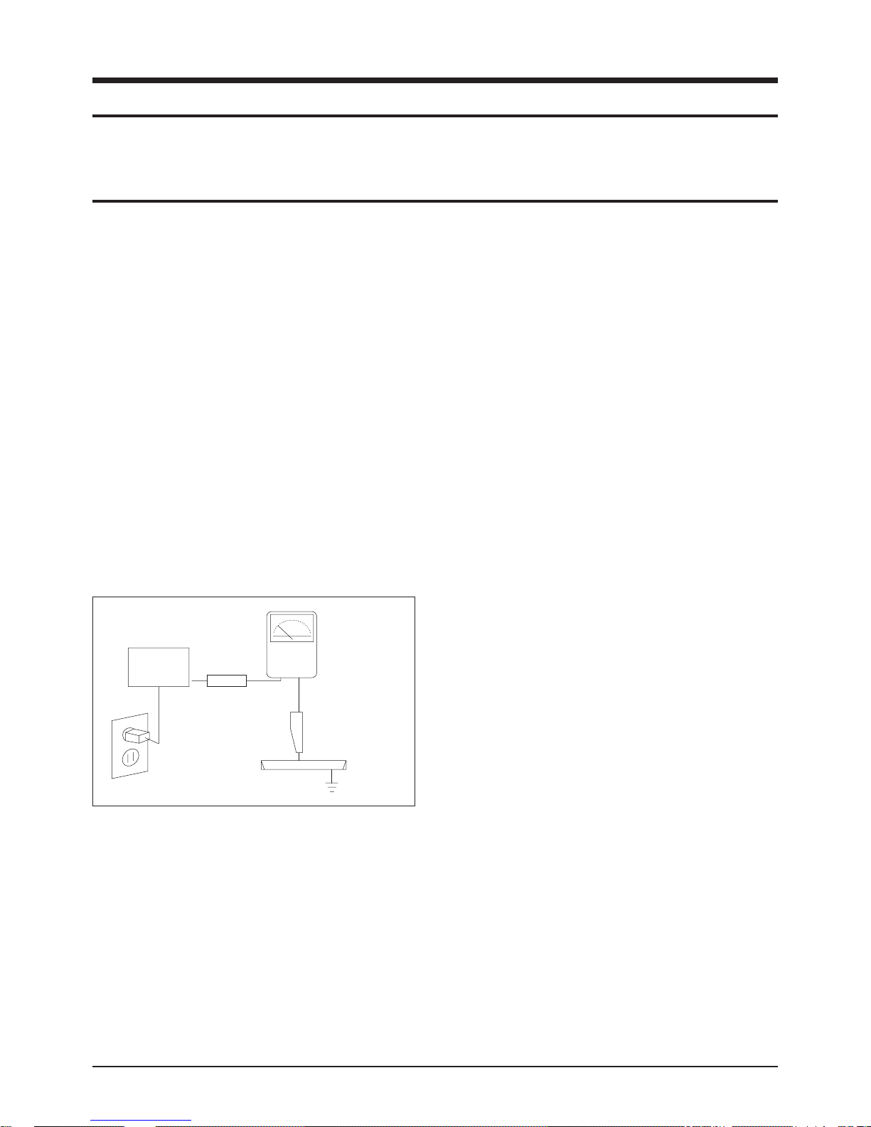
3. Check for Electricity Leakage (Figure 1-1)
Warning: Do not use an insulated transistor for checking
the leakage. Use only those current leakage testers or
mirroring systems that comply with ANSIC 101.1 and the
Underwriter Laboratory's specifications (UL1410, 59.7).
Fig. 1-1 AC Leakage Test
4. A high voltage is maintained within the specified limits
using safety parts, calibration and tolerances. When
voltage exceeds the specified limits, check each special
part.
5. Warning for Engineering Changes:
Never make any changes or additions to the circuit
design or the internal part for this product.
Ex: Do not add any audio or video accessory
connectors. This might cause physical damage.
Furthermore, any changes or additions to the original
design/engineering will invalidate the warranty.
6. Warning - Hot Chassis:
Some TV chassis are directly connected to one end of
the AC power cord for electrical reasons.
Without insulated transistors, the product can only be
repaired safely when the chassis is connected to the
earthed end of the AC power source.
To make sure the AC power cord is properly connected,
follow the instructions below. Use the voltmeter to
measure the voltage between the chassis and the
earthed ground. If the measurement is over 1.0V, unplug
the AC power cord and change the polarity before reinserting it. Measure the voltage between the chassis
and the ground again.
7. Some TV chassis are shipped with an additional
secondary grounding system. The secondary system is
adjacent to the AC power line. These two grounding
systems are separated in the circuit using an
unbreakable/unchangeable insulation material.
8. When any parts, material or wiring appear overheated or
damaged, replace them with new regular ones
immediately. When any damage or overheating is
detected, correct this immediately and make a regular
check of possible errors.
9. Check for the original shape of the lead, especially that
of the antenna wiring, any sharp edges, the AC power
and the high voltage power. Carefully check if the wiring
is too tight, incorrectly placed or loose. Never change the
space between the part and the printed circuit board.
Check the AC power cord for possible damages. Keep
the part or the lead away from any heat-emitting
materials.
Precaution
Samsung Electronics 1-1
To avoid possible damages or electric shocks or exposure to radiation, follow the instructions below with regard to safety,
installation, service and ESD..
1. Precaution
1-1 Safety Precautions
(READING SHOULD
DEVICE
UNDER
TEST
EXPOSED METAL
2-WIRE CORD
ALSO TEST WITH
PLUG REVERSED
(USING AC ADAPTER
PLUG AS REQUIRED)
TEST ALL
SURFACES
LEAKAGE
CURRENT
TESTER
NOT BE ABOVE
0.5mA)
EARTH
GROUND

10. Safety Indication:
Some electrical circuits or device related materials
require special attention to their safety features, which
cannot be viewed by the naked eye. If an original part is
replaced with another irregular one, the safety or
protective features will be lost even if the new one has a
higher voltage or more watts.
Critical safety parts should be bracketed with ( ).
Use only regular parts for replacements (in particular,
flame resistance and dielectric strength specifications).
Irregular parts or materials may cause electric shock or
fire.
Precaution
1-2 Samsung Electronics
!

1. The service instructions are printed on the cabinet, and
should be followed by any service personnel.
2. Make sure to unplug the AC power cord from the power
source before starting any repairs.
(a) Remove or re-install parts or assemblies.
(b) Disconnect the electric plug or connector, if any.
(c) Connect the test part in parallel with the electrolytic
capacitor.
3. Some parts are placed at a higher position than the
printed board. Insulated tubes or tapes are used for this
purpose. The internal wiring is clamped using buckles to
avoid contact with heat emitting parts. These parts are
installed back to their original position.
4. After the repair, make sure to check if the screws, parts
or cables are properly installed. Make sure no damage is
caused to the repaired part and its surroundings.
5. Check for insulation between the blade of the AC plug
and that of any conductive materials (i.e. the metal
panel, input terminal, earphone jack, etc).
6. Insulation Check Process: Unplug the power cord from
the AC source and turn the switch on. Connect the insulating resistance meter (500v) to the AC plug blade.
The insulating resistance between the blade of the AC
plug and that of the conductive material should be more
than 1 ㏁.
7. Any B+ interlock should not be damaged.
If the metal heat sink is not properly installed, no
connection to the AC power should be made.
8. Make sure the grounding lead of the tester is connected
to the chassis ground before connecting to the positive
lead. The ground lead of the tester should be removed
last.
9. Beware of risks of any current leakage coming into
contact with the high-capacity capacitor.
10. The sharp edges of the metal material may cause
physical damage, so ensure wearing protective gloves
during the repair.
Precaution
Samsung Electronics 1-3
Warning 1: First carefully read the "Safety Instruction" in this service manual.
When there is a conflict between the service and the safety instructions, follow the safety instruction at all times.
Warning 2: Any electrolytic capacitor with the wrong polarity will explode.
1-2 Servicing Precautions

1-3 Static Electricity Precautions
1. Some semi-conductive ("solid state") devices are
vulnerable to static electricity. These devices are known
as ESD. ESD includes the integrated circuit and the field
effect transistor. To avoid any materials damage from
electrostatic shock, follow the instructions described
below.
2. Remove any static electricity from your body by
connecting the earth ground before handling any
semi-conductive parts or ass'ys. Alternatively, wear a
dischargeable wrist-belt.
(Make sure to remove any static electricity before
connecting the power source - this is a safety instruction
for avoiding electric shock)
3. Remove the ESD ass'y and place it on a conductive
surface such as aluminum foil to prevent accumulating
static electricity.
4. Do not use any Freon-based chemicals.
Such chemicals will generate static electricity that
causes damage to the ESD.
5. Use only grounded-tip irons for soldering purposes.
6. Use only anti-static solder removal devices.
Most solder removal devices do not support an
anti-static feature. A solder removal device without an
anti-static feature can store enough static electricity to
cause damage to the ESD.
7. Do not remove the ESD from the protective box until the
replacement is ready. Most ESD replacements are
covered with lead, which will cause a short to the entire
unit due to the conductive foam, aluminum foil or other
conductive materials.
8. Remove the protective material from the ESD
replacement lead immediately after connecting it to the
chassis or circuit ass'y.
9. Take extreme caution in handling any uncovered ESD
replacements. Actions such as brushing clothes or lifting
your leg from the carpet floor can generate enough static
electricity to damage the ESD.
Precaution
1-4 Samsung Electronics
CAUTION
These servicing instructions are for use by
qualified service personnel only.
To reduce the risk of electric shock do not
perform any servicing other than that contained in the
operating instructions unless you are qualified to do so.

Precaution
Samsung Electronics 1-5
1-4 Installation Precautions
1. For safety reasons, more than two people are required
for carrying the product..
2. Keep the power cord away from any heat emitting
devices, as a melted covering may cause fire or electric
shock.
3. Do not place the projector in areas with poor ventilation
such as a bookshelf or closet. The increased internal
temperature may cause fire.
4. Bend the external antenna cable when connecting it to
the product. This is a measure to protect it from being
exposed to moisture. Otherwise, it may cause a fire or
electric shock.
5. Make sure to turn the power off and unplug the power
cord from the outlet before removing the product. Also
check the antenna cable or the external connectors if
they are fully unplugged. Damage to the cord may cause
fire or electric shock.
6. Keep the antenna far away from any high-voltage cables
and install it firmly. Contacting the high-voltage cable or
the antenna falling over may cause fire or electric shock.
7. When connecting the RF antenna, check for a DTV
receiving system and install a separate DTV reception
antenna for areas with no DTV signal.
8. Check the basics of the screen test.
- Image position/size, Tilt adjustment

1-6 Samsung Electronics
MEMO
Product Specification
Samsung Electronics 2-1
2. Product Specification
2-1 Product Features
Block Specfication Remark
CRT
34" FLAT CRT
32" FLAT CRT
29" FLAT GREEN CRT(H/V:26.5kV)
29" FLAT CRT(H/V 30kV)
28" FLAT CRT
25" FLAT CRT
RF Part - LNA & 2TUNER PIP F/S TUNER TUNER(PIP,LNA) OPTION
Power
- WORLD WIDE INPUT VOLTAGE RANGE
- STD-BY : 3W UNDER
STR-W6750F
Video
- PAL/SECAM/NT(CIS MODEL)
- BASIC 100Hz
SDA5550
VSP9402
CXA2180Q
SOUND
- Output : 10W X2
- Function : NICAM/A2 STEREO,
SRS,WOW
TURBO
STV8237, TDA7297SA
■ Core Parts Functions
- VSP9402 : RF-CVBS, EXT-CVBS, FRONT Y,C,SCART1 R G B, Video Signal Processing.
- CXA2180Q : H-out, VD-P, VD-N, RGB out, Video and Deflection Signal Processing.
- SDA5550M : IIC-Comunication, Master Control Micom
- M27W201 : ROM MICOM
- TDA7266SA : 10W Sound Output BTLAMP
- LA7845 : Vertical Deflection AMP
- TDQ-6F(or 6L) : F/S PAL Tuner(LNA Option)
- TDA6109JF : R/G/B Drive AMP IC

Product Specification
2-2 Samsung Electronics
2-2 Key Features
Model CW-29M066V
Voltage 220 V
Frequency of Operation 50 Hz
Dimensions(mm) 730X485X575
Weight 43.5Kg
■ H/W Configuration
- 480i 60/50Hz
- Multi System
- Digital 100Hz
- Multi PIP
■ S/W Configuration
- 200 Page TTX(EAST, ASIA, CIS), 10page TTX(EAST ASIA, CIS)
- Multi System PAL/SECAM/NTSC4.43/NTSC3.58
- Auto wide, CM Label, Pre channel, On/off timer
- New LTI OSD
■ Picture
- System : PAL/SECAM/NTSC4.43/NTSC3.58
- Digital 100Hz
- Black Level expantion, CTI, VM, LTI
- AKB(Auto kinetic Bias)
- Still picture, Digital Noise reduction
- Panorama : Wide Model
■ Sound
- Sound System : A2, Nicam Stereo
- SRS WOW
- Output : 10W+10W
- AVL, Melody, Auto Stereo, Auto Mute, Equalizer
■ Feature
- Picture Size : 16:9/Panorama/Zoom1/Zoom2/4:3
- Auto Program
- Sleep Timer : 180 Min.
- Clock
- Zoom, Previous channel, White Screen, Color Tone
- Multi PIP

Product Specification
Samsung Electronics 2-3
■ In/Out Terminals
- Side : 1 CVBS Input, 1 S-VHS Input
- Rear
*EU, CIS : 42p 2-SCART Input/Output (SCART1 RGB Input)
■ Remocon
- Universal : TM76
■ Power Supply
- AC230 50Hz/60Hz (Europe)
- AC100-240V 50Hz/60Hz (East Asia)
- AC160-300 50Hz/60Hz (CIS)
■ Power Comsumption
- Standy-by : 3W
Product Specification
2-4 Samsung Electronics
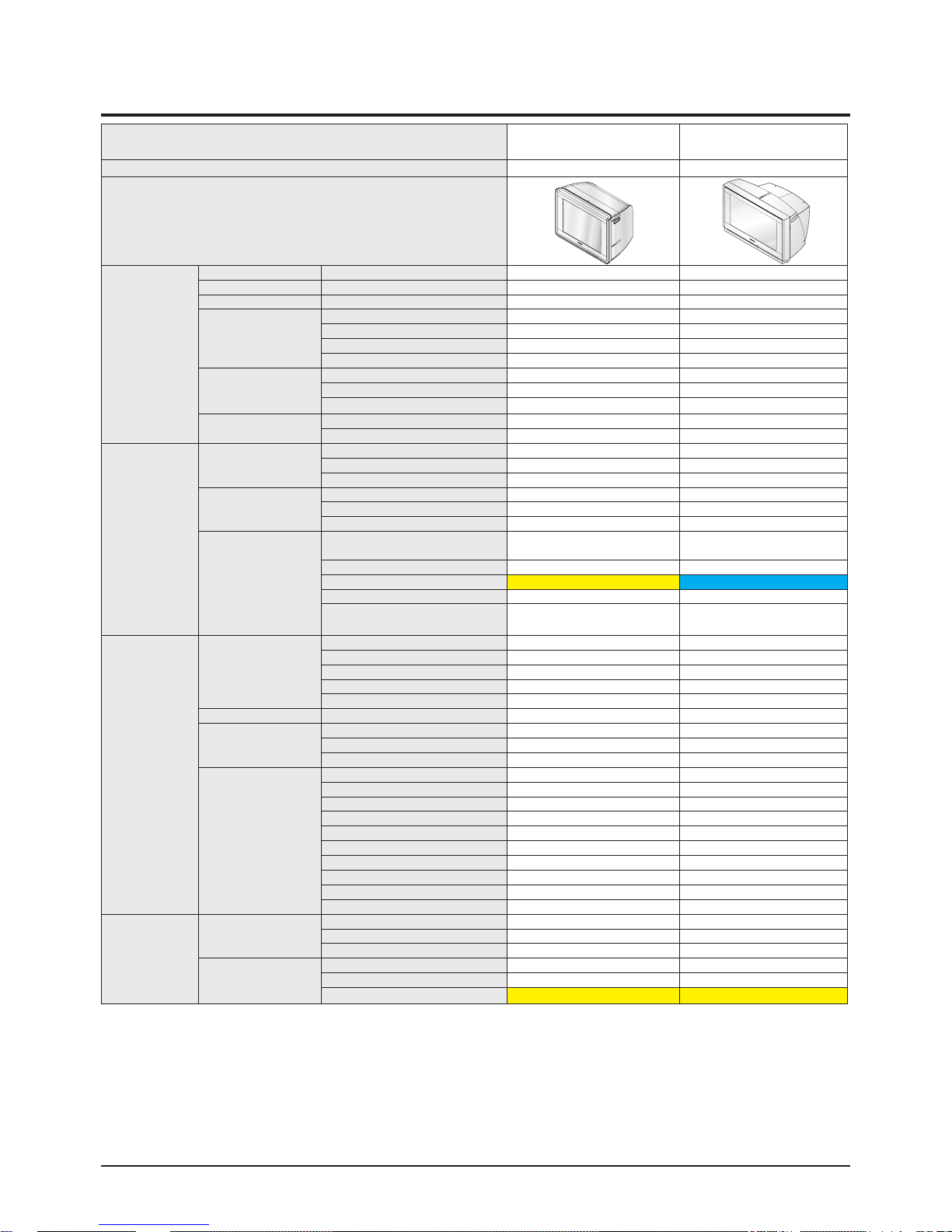
2-3 Specifications Analysis
Model
WS-32M30SSPN
Negotiator
CW-29M166V
Negotiator2
Chassis S61A S61B
Design
Picture
DNIe DNIe/DNIe Jr -/- -/-
Noise Reduction NR / DNR DNR DNR
Low Noise Amplifier LNA O O
Picture Control
Color Tone O O
Auto White Balance Control - -
Tilt Control MoO O
Scan Mode Selection - -
Display
Screen Aspect Ratio(16:9/4:3) 16:9 16:9
Visible Diagonal 32" 32"
Type (Flat / Curved) Flat Flat
Picture Function
3:2 Pull Down - -
Auto Knietic Bias(AKB) O O
Sound
Stereo Type
Nicam / A2 Stereo O/O O/O
Line Stereo (AV Stereo) / Mono O/O O/O
Pseudo (Except Mono type) O O
Sound Control
Auto Stereo O O
Base/ Treble/ Balance -/-/O -/-/O
Sound Equalizer O O
Sound Effect System
(Surround System)
DTS (Digital Theater Sound) /
Dolby Digital (AC3)
- -
Dolby Prologic / Dolby Prologic 2 - -
Virtual Dolby Virtual Dolby SRS WOW
BBE - -
Samsung Sound Effect (Turbo/Turbo
Plus/MDB, ETC)
Turbo Turbo
Features
CH
ATM (ATS) - -
Channel Skip O O
Channel Add/Erase O/O O/O
Channel Labeling O O
Previous Channel O O
PIP PIP Channel Scan - X
Timer
On/Off Timer O O
Sleep Timer O O
Auto Clock Set/manual clock set -/O -/O
TeleText
Teletext 10P 10P
Blue Screen On/Off O O
Melody On-Off O O
Plug & Play O O
Absent Power Off O O
Auto Power Off O O
Picture Size Control(Zoom&Wide/Zoom) O/- O/-
Picture Mode Select (5mode / 3mode) 4 mode 4 mode
Auto Wide O O
Help(on OSD Menu) O O
Terminals
Side In & Out Jacks
Composite (AV) O O
Y/C (S-Video) O O
Headphone(Earphone) - -
Rear Input Jacks
ANT.(RF) O O
Euro Scart 2 Scart 2 Scart
Audio Monitor Out O -
Product Specification
Samsung Electronics 2-5
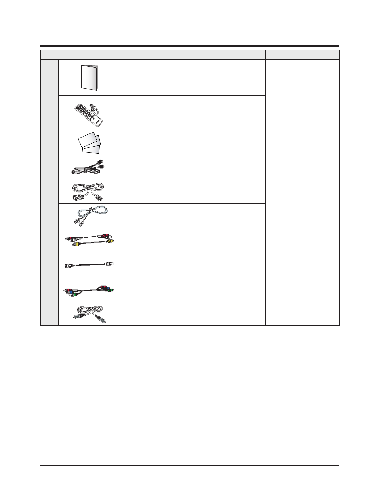
2-4 Accessories
Accessories Item Item code Remark
Supplied Accessories
User Manual -
Samsung Service Center
Remote Control/
Alkaline Battery
(1.5V AAA)2EA
AA59-00370B/
4301-000121
Warranty Card -
Accessories that can be
purchased additionally
Coaxial Cable -
Internal shopping mall
HDMI/DVI Cable -
HDMI Cable -
Video/Audio Cable -
S-Video Cable -
Component Cable -
Optical Cable -

2-6 Samsung Electronics
MEMO

Alignment & Adjustment
Samsung Electronics 3-1
3. Alignment & Adjustment
3-1 Service Instruction
1. General Adjustment :
In general, a color TV can provide ideal visual quality by adjusting the basic settings such as the vertical size, horizontal size,
focus, etc. Display a black and white picture on the screen to check if the picture is clearly displayed.
If there are some 'spotted' points on the screen when displaying a black and white picture, degauss the screen using the
degauss coil. If the spotted points remain, re-adjust the purity and the convergence. This completes the basic performance
examination.
Notice.
■ These adjustments and the check list are only applied to S61B chassis-applied models.
■ Only use 230V for the measurement set. It is recommended using an insulation transformer when supplying power to
the set so as to prevent shock to the set or to yourself.
■ These adjustment specifications have been created on the basis of the domestic S61B chassis-applied remote control
Smodel. Some of the contents may be changed subject to the sales location and the product specifications.
2. When replacing the Deflection Board:
Tilt adjustment, focus adjustment, screen voltage setting and W/B adjustment are all required
3. When replacing the F-box Board :
Since the software is loaded to the flash memory of F-box board, check the version of the software after replacing the board.
To check the version of the software, Enter service mode press the key on the remote control according to the
following seguenu.(in stand-by status) Info→Menu→Mute→Power→ON
The software information will then be displayed below the OSD menu.The notation of the software information
: For example T_NGTPEU1_0006Since the settings including the Channel information, Deflection, etc. are saved to the
nvRAM, reconfigure these settings when replacing the F-box Board.
4. When replacing the CRT Ass'y : No adjustments required.
5. When replacing the front panel master power switch : No adjustments required.
6. When replacing the Side AV : No adjustments required.
7. When replacing the control switch : No adjustments required.
Alignment & Adjustment
3-2 Samsung Electronics
3-2 How to Access Service Mode
1. To enter Service Mode, press the keys on the remote control according to the following sequence. (in Stand-by status)
Info → Menu → Mute → Power On
※ When failing to enter Service Mode, repeat the procedure above.
2. The initial screen of Service Mode.
3. Functions of the Keys within Service Mode
Service/T-NG2PEU_XXX
Option(XX XX XX)
Deflection
Video Adjust 1
Video Adjust 2
Video Adjust 3
Video Adjust 4
Video Adjust 5
YC Delay
EEPROM
Checksum(0000)
Reset/XX-XX-XX XXPage
MENU Show all menus
▲ / ▼
Move the cursor to select an item.
◀ / ▶
Adjust the selected configuration value
Alignment & Adjustment
Samsung Electronics 3-3
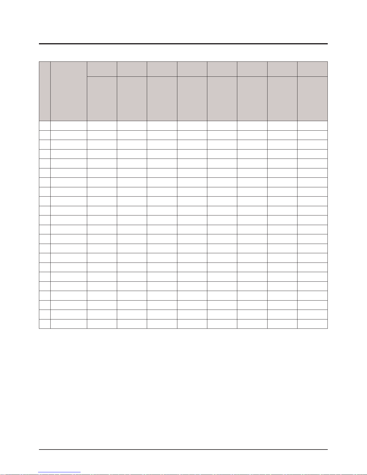
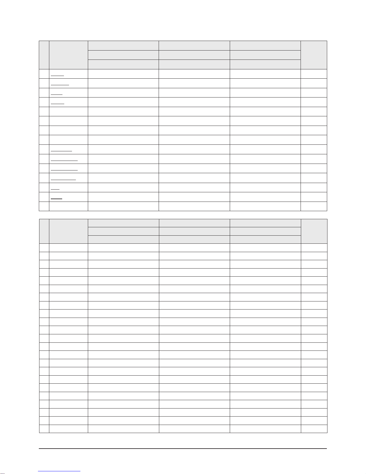
3-3 Factory Data
★ The underlined are items applied during the service adjustment. None of the others should be adjusted.
1. Option Byte1 (Russia)
No Item
25"[0.315mH] 25"[0.315mH] 25"[0.315mH] 29" [0.28mH] 29" [0.28mH] 29" [0.28mH] 32"[0.28mH] 32"[0.28mH]
CS25M6SPQ CS25M6SSQ CS25M6SQQ
CS29M6SPQ
CS29A11SPQ
CS34A11SPQ
CS29M6SSQ
CS29A11SSQ
CS34A11SSQ
CS29M6SQQ WS32A11SPQ WS32A11SSQ
1 CRT 4:3 4:3 4:3 4:3 4:3 4:3 WIDE WIDE
2 Osd Group CIS CIS CIS CIS CIS CIS CIS CIS
3 Osd Language CIS CIS CIS CIS CIS CIS CIS CIS
4 AV-Jack Scart Scart Scart Scart Scart Scart Scart Scart
5 DTV Off Off Off Off Off Off Off Off
6 PIP 2-TUNER Off Off 2-TUNER Off Off 2-TUNER Off
7 LNA On On On On On On On On
8 Search_LNA On On On On On On On On
9 SOUND SRS SRS A2/NICAM SRS SRS A2/NICAM SRS SRS
10 Auto FM On On On On On On On On
11 Carrier mute Off Off Off Off Off Off Off Off
12 HIGH Deviation Off Off Off Off Off Off Off Off
13 Woofer Off Off Off Off Off Off Off Off
14 TTX Group Russia Russia Russia Russia Russia Russia Russia Russia
15 TTX LIST PRI Off Off Off Off Off Off Off Off
16 TTX ON/OFF On On On On On On On On
17 DTV1080I 50HZ 50HZ 50HZ 50HZ 50HZ 50HZ 50HZ 50HZ
18 Digital NR On On On On On On On On
19 AGC Off Off Off Off Off Off Off Off
20 Tilt Off Off Off On On On On On
21 Speaker Non Dome Non Dome Non Dome Non Dome Non Dome Non Dome Non Dome Non Dome
22 HOTEL MODE OFF OFF OFF OFF OFF OFF OFF OFF
Alignment & Adjustment
3-4 Samsung Electronics
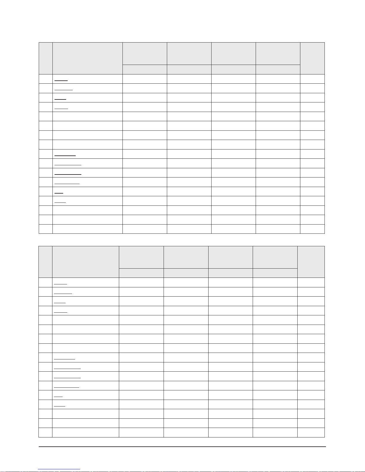
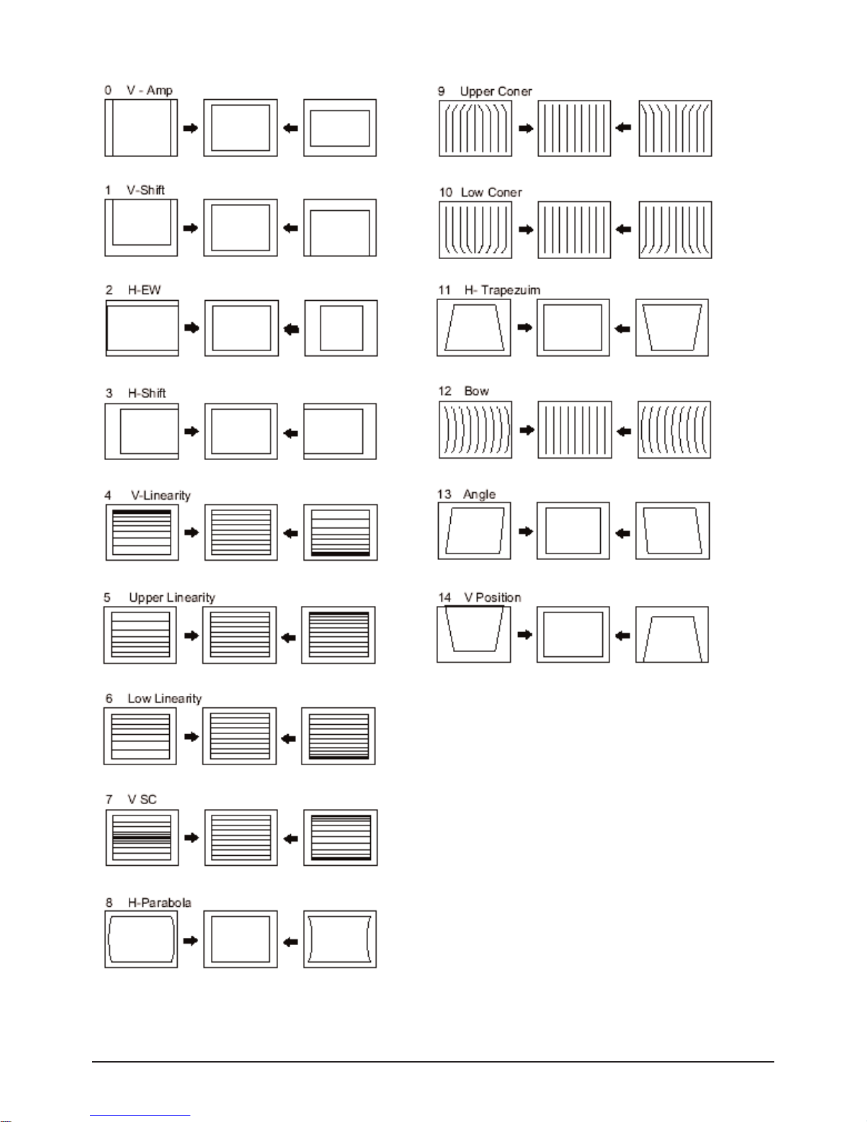
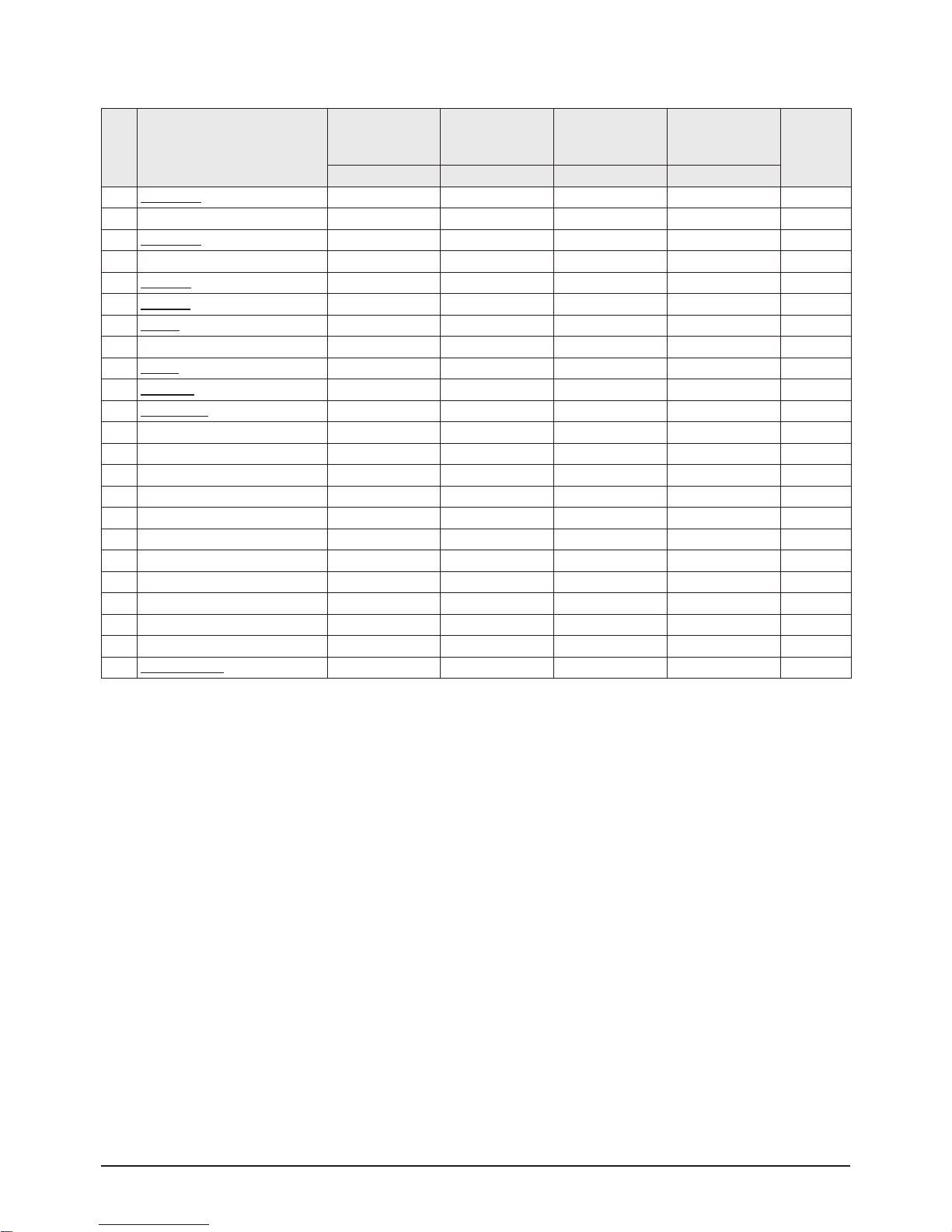
2. Deflection Adiustment (PAL)
No Item
CS25M6SPQ
CS25M6SSQ
CS25M6SQQ
CS29M6SPQ
CS29M6SSQ
CS29M6SQQ
WS32A11SPQ
WS32A11SSQ
CS34A11SPQ
CS34A11SSQ
Remark
25" 29" 32" 34"
0 V Amp 45 23 20 23->29 Adjust
1 V_SHIFT 30 22 29 25->23 Adjust
2 H EW 33 40 40 30->28 Adjust
3 H Shift 35 22 36 20->21 Adjust
4 V Linearity 4 6 11 7 FIX
5 Upper-Linearity 8 8 10 6 FIX
6 Lower-Linearity 4 4 0 2 FIX
7 V SC 5 5 0 5 FIX
8 H Parablar 32 33 38 33->20 Adjust
9 Upper Corner 32 34 21 37->34 Adjust
10 Lower Corner 32 34 33 41->40 Adjust
11 H Trapezium 32 41 15 20->26 Adjust
12 Bow 32 31 31 32->30 Adjust
13 Angle 31 31 32 32 Adjust
14 V Position 40 40 40 40 FIX
15 CXA 2151 Sub01 68 68 68 68 FIX
16 CXA 2151 Sub01 1 1 1 1 FIX
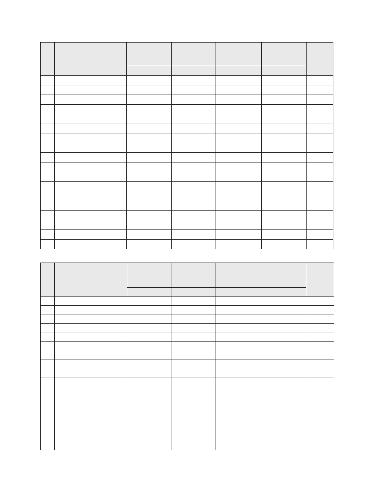
3. Deflection Adiustment (NTSC)
No Item
CS25M6SPQ
CS25M6SSQ
CS25M6SQQ
CS29M6SPQ
CS29M6SSQ
CS29M6SQQ
WS32A11SPQ
WS32A11SSQ
CS34A11SPQ
CS34A11SSQ
Remark
25" 29" 32" 34"
0 V Amp cc 0 0 -2 Adjust
1 V_SHIFT 2 3 3 2 Adjust
2 H EW 1 1 0 0 Adjust
3 H Shift 9 6 6 6 Adjust
4 V Linearity 2 2 2 1 FIX
5 Upper-Linearity 1 1 1 1 FIX
6 Lower-Linearity -1 -1 -1 -2 FIX
7 V SC 0 0 0 0 FIX
8 H Parablar 0 1 -1 1 Adjust
9 Upper Corner 2 0 0 -2 Adjust
10 Lower Corner 0 2 0 2 Adjust
11 H Trapezium -8 -5 -4 -12 Adjust
12 Bow 1 1 1 0 Adjust
13 Angle -3 2 -2 -1 Adjust
14 V Position 0 0 0 0 FIX
15 CXA 2151 Sub01 68 68 68 68 FIX
16 CXA 2151 Sub01 1 1 1 1 FIX
Alignment & Adjustment
Samsung Electronics 3-5
Alignment & Adjustment
3-6 Samsung Electronics
4. Video Adjustment 1
No Item
CS25M6SPQ
CS25M6SSQ
CS25M6SQQ
CS29M6SPQ
CS29M6SSQ
CS29M6SQQ
WS32A11SPQ
WS32A11SSQ
CS34A11SPQ
CS34A11SSQ
Remark
25" 29" 32" 34"
0 R_CUTOFF 34 40 49 50 s Adjust
1 G_CUTOFF 25 25 25 25 FIX
2 B_CUTOFF 26 26 31 38 Adjust
3 Color On / Off 1 1 1 1 FIX
4 CR Offset 35 35 35 35 Adjust
5 CB Offest 25 25 25 25 Adjust
6 R Drive 37 39 26 45 Adjust
7 G Drive 25 25 25 25 FIX
8 B Drive 29 26 19 27 Adjust
9 Sub Bright 37 46 51 48 Adjust
10 Sub Contrast 4 7 6 10 Adjust
11 Sub Color 20 20 20 20 FIX
12 Secam sub color 2 2 2 2 FIX
13 Sub Tint 28 28 28 28 FIX
14 CTI Level 2 2 2 2 FIX
15 R-Y/R 15 15 15 15 FIX
16 R-Y/B 15 15 15 15 FIX
17 G-Y/R 9 9 9 9 FIX
18 G-Y/B 6 6 6 6 FIX
19 LTI Level 0 0 0 0 FIX
20 VSU 2 2 2 2 FIX
21 Melody volume 9 9 9 9 FIX
22 Video mute time 6 6 6 6 Adjust
Alignment & Adjustment
Samsung Electronics 3-7
5. Video Adjustment 2
No Item
CS25M6SPQ
CS25M6SSQ
CS25M6SQQ
CS29M6SPQ
CS29M6SSQ
CS29M6SQQ
WS32A11SPQ
WS32A11SSQ
CS34A11SPQ
CS34A11SSQ
Remark
25" 29" 32" 34"
0 ABL Mode 3 3 3 3 FIX
1 Gamma 2 2 3 3 FIX
2 DPIC Level 2 2 2 2 FIX
3 DC Trans 2 2 2 2 FIX
4 ABL-TH 14 14 14 14 FIX
5 VM-Level 1 1 1 1 FIX
6 VM-F0 0 0 0 0 FIX
7 VM-Delay 3 3 3 3 FIX
8 SHP-F0 0 0 0 0 FIX
9 PRE Over 0 0 0 0 FIX
10 AKB Time 15 15 13 15 FIX
11 Coring 00 00 00 00 FIX
12 Bandpass 7 7 7 7 FIX
13 Highpass 8 8 8 8 FIX
14 Bandpass_AV 6 6 6 6 FIX
15 Highpass_AV 7 7 7 7 FIX
16 FLCOL_SW 1 1 1 1 FIX
17 FLCOL 0 0 0 0 FIX
6. Video Adjustment 3
No Item
CS25M6SPQ
CS25M6SS7Q
CS25M6SQQ
CS29M6SPQ
CS29M6SSQ
CS29M6SQQ
WS32A11SPQ
WS32A11SSQ
CS34A11SPQ
CS34A11SSQ
Remark
25" 29" 32" 34"
0 H_EHT comp 4 5 7 2 FIX
1 V_EHT comp 4 6 6 2 FIX
2 NR OFF Value 6 6 6 6 FIX
3 PIP Contrast 13 13 13 13 FIX
4 PIP Bright 0 0 0 0 FIX
5 PIP Tint 63 63 63 63 FIX
6 PIP Color 7 7 7 7 FIX
7 PIP Pal V Pos 28 28 28 28 FIX
8 PIP NTSC V Pos 25 25 25 25 FIX
9 PIP H Pos 34 34 34 34 FIX
10 PIP R Cut off 0 0 0 0 FIX
11 PIP G Cut off 0 0 0 0 FIX
12 PIP B Cut off 0 0 0 0 FIX
13 PIP R Drive 56 56 56 56 FIX
14 PIP G Drive 56 56 56 56 FIX
15 PIP B Drive 56 56 56 56 FIX
16 PIP VSP Delay 5 5 5 5 FIX
Alignment & Adjustment
3-8 Samsung Electronics
7. Video Adjustment 4
No Item
CS25M6SPQ
CS25M6SSQ
CS25M6SQQ
CS29M6SPQ
CS29M6SSQ
CS29M6SQQ
WS32A11SPQ
WS32A11SSQ
CS34A11SPQ
CS34A11SSQ
Remark
25" 29" 32" 34"
0 3Pip Pal V position 12 12 11 12 Adjust
1 3Pip Pal H Position 13 13 12 13 Adjust
2 3Pip Ntsc V Position 11 11 11 11 Adjust
3 3Pip Ntsc H Position 19 19 19 19 Adjust
4 Sync Phase (480p) 0 0 0 0 FIX
5 Sync Phase (576p) 1 1 1 1 FIX
6 Sync Phase (1080i) 0 0 0 0 FIX
8. YC DELAY
No Item
CS25M6SP7X/BWT
CS25M6SS7X/BWT
CS25M6SQ7S/ELD
CS29M6SP7X/BWT
CS29M6SS7X/BWT
CS29M6SQ7S/ELD
WS32A11SP7XBWT
WS32A11SS7XBWT
CS34A11SP7SBWT
CS34A11SS7SBWT
Remark
25" 29" 32" 34"
0 P.YC (AV) Delay -9 -9 -9 -9 FIX
1 S.YC (AV) Delay -8 -8 -8 -8 FIX
2 N.YC (AV) Delay -8 -8 -8 -8 FIX
3 P.BG.YC Delay -8 -8 -8 -8 FIX
4 P.DK.YC Delay -10 -10 -10 -10 FIX
5 P.I.YC Delay -10 -10 -10 -10 FIX
6 P.M.YC DELAY -9 -9 -9 -9 FIX
7 P.L.YC Delay -8 -8 -8 -8 FIX
8 S.BG.YC Delay -6 -6 -6 -6 FIX
9 S.DK.YC Delay -8 -8 -8 -8 FIX
10 S.I.YC Delay -10 -10 -10 -10 FIX
11 S.M4.43.YC DELAY -10 -10 -10 -10 FIX
12 S.L.YC Delay -5 -5 -5 -5 FIX
13 N.M.YC Delay -7 -7 -7 -7 FIX
Alignment & Adjustment
Samsung Electronics 3-9
9.EEPROM
No Item 25" 29" 32" 34" Remark
0 System 0 0 0 0 FIX
1 System (VGA) 0 0 0 0 FIX
2 System (480p) 0 0 0 0 FIX
3 System (1080i) 0 0 0 0 FIX
4 Dynamic Contrast 90 90 90 90 FIX
5 Dynamic Brightness 50 50 50 50 FIX
6 Dynamic Shapness 55 55 55 55 FIX
7 Dynamic Color 35 35 35 35 FIX
8 Dynamic Tint 50 50 50 50 FIX
9 Dynamic Color Tone 2 2 2 2 FIX
10 Standard Contrast 70 70 70 70 FIX
11 Standard Brightness 50 50 50 50 FIX
12 Standard Shapness 50 50 50 50 FIX
13 Standard Color 50 50 50 50 FIX
14 Standard Tint 50 50 50 50 FIX
15 Standard Color Tone 2 2 2 2 FIX
16 Movie Contrast 40 40 40 40 FIX
17 Movie Brightness 50 50 50 50 FIX
18 Movie Shapness 40 40 40 40 FIX
19 Movie Color 45 45 45 45 FIX
20 Movie Tint 50 50 50 50 FIX
21 Movie Color Tone 2 2 2 2 FIX
22 Left Blanking (PAL) 255 255 255 255 FIX
23 Right Blanking (PAL) 255 255 255 255 FIX
24 Left Blanking (VGA) 255 255 255 255 FIX
25 Right Blanking (VGA) 255 255 255 255 FIX
26 Left Blanking (480p) 215 215 215 215 FIX
27 Right Blanking(480p) 105 105 105 105 FIX
28 Left Blanking(1080i) 141 141 141 141 FIX
29 Right Blanking(1080i) 109 109 109 109 FIX
30 Brightness (RGB) 236 236 236 236 FIX
31 Contrast (RGB) 165 165 169 169 FIX
32 U Saturation (RGB) 94 94 94 94 FIX
33 V Saturation (RGB) 36 36 36 36 FIX
34 DVD Brightness (YPbPr) 255 255 255 255 FIX
35 DVD Contrast (YPbPr) 160 160 160 160 FIX
36 DVD U Saturation (YPbPr) 230 230 230 230 FIX
37 DVD V Saturation (YPbPr) 38 38 38 38 FIX
38 9402 Y Gain 200 200 200 200 FIX
39 9402 U Gain 85 85 85 85 FIX
40 - 255 255 255 255 FIX
41 9402 V Gain 75 75 75 75 FIX
42 CrCb Gain (480p) 119 119 11 9 11 9 FIX
43 CrCb Gain (1080i) 11 9 11 9 119 11 9 FIX
44 LTI Mode 2 2 2 2 FIX
45 LTI Mode (VGA) 255 255 255 255 FIX
Alignment & Adjustment
3-10 Samsung Electronics
No Item 25" 29" 32" 34" Remark
46 LTI Mode (480p) 1 1 1 1 FIX
47 LTI Mode (1080i) 1 1 1 1 FIX
48 NR ON value1 85 85 85 85 FIX
49 NR ON value2 85 85 85 85 FIX
50 NR OFF value1 68 68 68 68 FIX
51 NR OFF value2 68 68 68 68 FIX
52 NR ON value3 170 170 170 170 FIX
53 NR ON value4 170 170 170 170 FIX
54 NR OFF value3 34 34 34 34 FIX
55 NR OFF value4 34 34 34 34 FIX
56 - 255 255 255 255 FIX
57 SECAM °¨µµ 28 28 28 28 FIX
58 Range of R Gain 32 32 32 32 FIX
59 Range of G Gain 32 32 32 32 FIX
60 Range of B Gain 32 32 32 32 FIX
61 Range of F/B Gain 23 23 23 23 FIX
62 - 255 255 255 255 FIX
63 TTX V-Position 40 40 40 40 FIX
64 TTX H-Position 180 180 180 180 FIX
65 - 255 255 255 255 FIX
66 - 255 255 255 255 FIX
67 wide model 4:3 Normal Parabola 0 0 0 0 FIX
68 1080i 50HZ Trepezium 255 255 255 255 FIX
69 1080i 60HZ Trepezium 255 255 255 255 FIX
70 UP-UCG (Up Corner Semi Control) 0 0 0 0 FIX
71 LO-UCG (Low Corner Semi Control) 0 0 0 0 FIX
72 Vertical Slicing Level 15 15 15 15 FIX
73 Vertical Sync Lowpass-Filter 13 13 13 13 FIX
74 Amplifier Current Setting of Oscillator ad 2 2 2 2 FIX
75 PAL 185 185 185 185 FIX
76 Chroma (PAL) 215 215 215 215 FIX
77 Chroma PLLuto PLL 1 1 1 1 FIX
78 AV PAL 200 200 200 200 FIX
79 NT left blank 127 127 127 127 FIX
80 NT Right blank 126 126 126 126 FIX
81 Progressive TTX V Position 255 255 255 255 FIX
82 Progressive TTX H-Position 255 255 255 255 FIX
83 3Pip Pal V position 46 12 12 12 FIX
84 3Pip Pal H Position 35 13 13 13 FIX
85 3Pip Ntsc V Position 43 11 11 11 FIX
86 3Pip Ntsc H Position 30 30 30 30 FIX
87 - 22 22 22 22 FIX
88 - 27 27 27 27 FIX
89 - 255 255 255 255 FIX
90 RF SubBright 124 124 124 124 FIX
91 TTX Sub Brightness 235 235 235 235 FIX
92 Left Blanking 141 141 141 141 FIX
Alignment & Adjustment
Samsung Electronics 3-11
No Item 25" 29" 32" 34" Remark
93 Right Blanking 153 153 153 153 FIX
94 S - ABL 0 0 0 0 FIX
95 P - ABL 48 48 48 0 FIX
96 Picture Limit Level 3 3 3 3 FIX
97 OSD Level (LRGB2_LEV) 5 5 5 5 FIX
98 TTX Level (LRGB2_LEV) 3 3 3 3 FIX
99 AGCADJ1 230 230 230 230 FIX
100 AGCADJ2 110 11 0 110 11 0 FIX
101 ON TIMER CH memory 1 1 1 1 FIX
102 COMPONENT2 OSD Brightness 10 10 10 10 FIX
196 TNR1 207 207 207 207 FIX
197 TNR2 175 175 175 175 FIX
198 TNR3 149 149 149 149 FIX
199 TNR4 127 127 127 127 FIX
200 TNR5 99 99 99 99 FIX
201 TNR6 31 31 31 31 FIX
205 TNR1 156 156 156 156 FIX
206 TNR2 76 76 76 76 FIX
207 TNR3 64 64 64 64 FIX
250 EEPROM check sum 171 171 171 171 FIX
252 IKR Count 250 250 250 250 FIX
253 Start 40 40 40 40 FIX
254 End 150 150 150 150 FIX
Alignment & Adjustment
3-12 Samsung Electronics
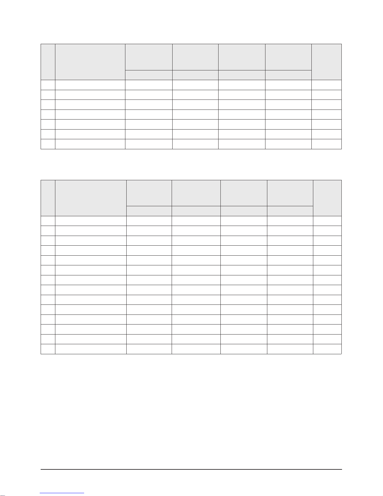
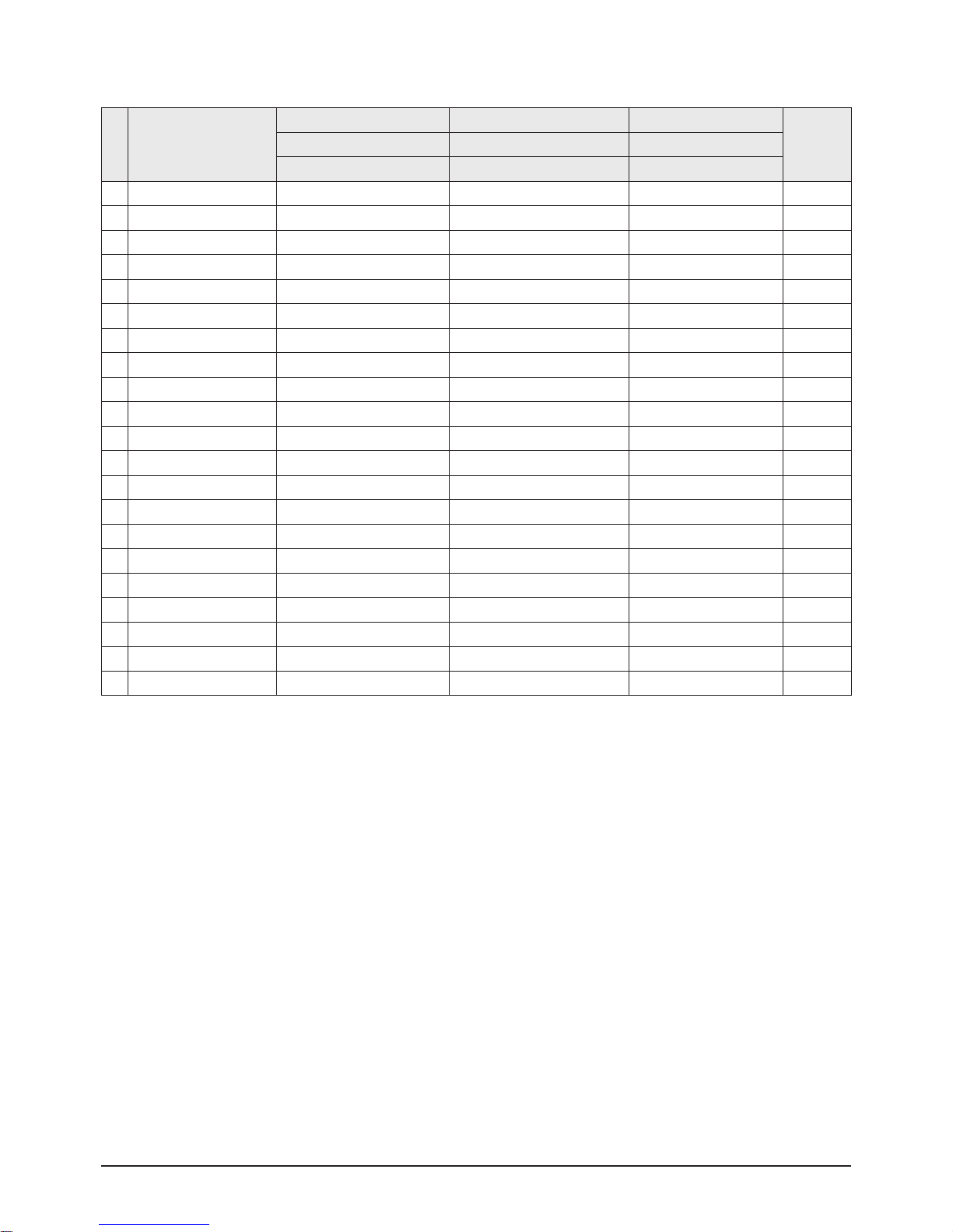
1. Option Byte2 (Europe)
No Item
SDI CRT(0.28mH) SDI CRT(0.28mH) SDI CRT(0.28mH)
Remark29" 28" 32"
CW29M206P7XXEC WS28M206P7XXEC WS32M206P7XXEC
0 V
Amp
30 40 25 Adjust
1 V_SHIFT 25 25 25 Adjust
2 H EW 35 30 30 Adjust
3 H Shift 35 25 25 Adjust
4 V Linearity 11 6 11 FIX
5 Upper-Linearity 10 6 10 FIX
6 Lower-Linearity 0 3 0 FIX
7 V SC 0 3 0 FIX
8 H Parablar 35 32 25 Adjust
9 Upper Corner 20 32 20 Adjust
10 Lower Corner 30 32 25 Adjust
11 H Trapezium 20 32 28 Adjust
12 Bow 33 32 32 Adjust
13 Angle 30 32 31 Adjust
14 V Position 40 40 40 FIX
2. Deflection Adiustment (PAL)
N
o
Item
SDI CRT(0.28mH) SDI CRT(0.28mH) SDI CRT(0.28mH)
29" 28" 32"
CW29M206P7X CW29M206T(V)7X WS28M2O6P7XXEC WS28M2O6T(V)7X WS32M2O6P7XXEC WS32M2O6T(V)7X
0 CRT 4;3 4;3 Wide Wide Wide Wide
1 AV-Jack Scart Scart Scart Scart Scart Scart
2 DTV OFF OFF OFF OFF OFF OFF
3 PIP 2-tuner off 2-tuner off 2-tuner off
4 LNA On off On off On off
5 SEARCH_LNA On off On off On off
6 SOUND SRS SRS SRS SRS SRS SRS
7 Auto FM On On On On On On
8 Tilt on/off Off Off ON ON ON ON
9 HIGH Deviation Off Off Off Off Off Off
10 Woofer Off Off Off Off Off Off
11 TTX Group Osd Language Osd Language Osd Language Osd Language Osd Language Osd Language
12 TTX LIST OFF OFF OFF OFF OFF OFF
13 Digital NR On On On On On On
14 AGC on/off Off Off Off Off Off Off
Alignment & Adjustment
Samsung Electronics 3-13
3. Deflection Adiustment (NTSC)_Offset
No Item
SDI CRT(0.28mH) SDI CRT(0.28mH) SDI CRT(0.28mH)
Remark29" 28" 32"
CW29M206P7XXEC WS28M206P7XXEC WS32M206P7XXEC
0 V Amp 0 0 0 Adjust
1 V_SHIFT -1 -1 -1 Adjust
2 H EW 1 1 1 Adjust
3 H Shift 6 6 6 Adjust
4 V Linearity -4 -4 -4 FIX
5 Upper-Linearity -1 -1 -1 FIX
6 Lower-Linearity 3 3 3 FIX
7 V SC 0 0 0 FIX
8 H Parablar 10→0 10→0 10→0 Adjust
9 Upper Corner 2 2 2 Adjust
10 Lower Corner -2 -2 -2 Adjust
11 H Trapezium 9→5 9→5 9→5 Adjust
12 Bow 0 0 0 Adjust
13 Angle 0 0 0 Adjust
14 V Position 0 0 0 FIX
4. Video Adjustment 1
No Item
SDI CRT(0.28mH) SDI CRT(0.28mH) SDI CRT(0.28mH)
Remark29" 28" 32"
CW29M206P7XXEC WS28M206P7XXEC WS32M206P7XXEC
0 R_CUTOFF, 40 40 40 Adjust
1 G_CUTOFF, 25 25 25 Adjust
2 B_CUTOFF, 35 35 35 Adjust
3 Color On / Off 01 01 01 FIX
4 CR Offset 35 35 35 Adjust
5 CB Offest 25 25 25 Adjust
6 R Drive 37 37 37 Adjust
7 G Drive 32 32 32 Adjust
8 B Drive 29 29 29 Adjust
9 Sub Bright 45 45 45 Adjust
10 Sub Contrast 4 4 4 Adjust
11 Sub Color 9 9 9 FIX
12 Secam sub color 5 5 5 FIX
13 Sub Tint 28 28 28 FIX
14 CTI Level 2 2 2 FIX
15 R-Y/R 15 15 15 FIX
16 R-Y/B 15 15 15 FIX
17 G-Y/R 9 9 9 FIX
18 G-Y/B 6 6 6 FIX
19 LTI Level 0 0 0 FIX
20 VSU 2 2 2 FIX
21 Melody volume 9 9 9 Adjust
22 Video mute time 6 6 6
Alignment & Adjustment
3-14 Samsung Electronics
5. Video Adjustment 2
No Item
SDI CRT(0.28mH) SDI CRT(0.28mH) SDI CRT(0.28mH)
Remark29" 28" 32"
CW29M206P7XXEC WS28M206P7XXEC WS32M206P7XXEC
0 ABL Mode 3 3 3 FIX
1 Gamma 2 3 3 FIX
2 DPIC Level 2 2 2 FIX
3 DC Trans 2 2 2 FIX
4 ABL-TH 14 14 14 FIX
5 VM-Level 1 1 1 FIX
6 VM-F0 0 0 0 FIX
7 VM-Delay 3 3 3 FIX
8 SHP-F0 0 0 0 FIX
9 PRE Over 0 0 0 FIX
10 AKB Time 15 13 13 FIX
11 Coring 00 00 00 FIX
12 Bandpass 7 7 7 FIX
13 Highpass 8 8 8 FIX
14 Bandpass_AV 6 6 6 FIX
15 Highpass_AV 7 7 7 FIX
16 FLCOL_SW 1 1 1 FIX
17 FLCOL 0 0 0 FIX
18 TRUBASS_CTRL(0XBA) O8 O8 O8 FIX
19 TRUBASS_LEVEL(0XBB) 1A 1A 1A FIX
20 NICAM MAE VALUE 255 255 255 FIX
 Loading...