

SAMSUNG TXH1972, CT5038, CT5039, CT331E, CT331H Diagram
...
9. PCB Layout
9-1 PCB-MAIN
PCB Layout
Samsung Electronics 9-1
D101 53 150
D102 56 130
D103 71 141
D201 135 196
D202 96 105
D203 96 107
D204 96 110
D205 123 92
D206 114 95
D207 114 97
D208 115 74
D210 99 105
D299 99 212
D301 32 139
D302 31 146
D401 85 99
D402 70 98
D403 59 74
D404 72 53
D405 81 38
D407 58 105
D601 124 213
D701 130 136
D702 227 203
D703 210 238
D704 85 159
D802 104 11
D803 150 23
D804 92 183
D805 168 42
D806 150 27
D807 186 51
D808 193 54
D809 186 67
D810 196 66
D814 99 60
D855 157 100
D856 147 101
D901 160 119
D902 163 110
D903 171 130
D904 132 96
D905 231 179
D906 157 131
DL01 105 219
DL02 108 219
DU01 211 118
DX01 116 107
DX02 111 101
DZ801 215 20
DZ802 179 30
DZ803 178 24
DZ806 157 17
DZ807 150 20
DZ901 231 83
DZ902 231 156
DZ903 203 124
IC201 100 164
IC301 50 132
IC601 146 225
IC602 168 221
IC801 155 10
IC802 141 97
IC901 215 153
IC902 219 178
ICK01 69 213
Q151 61 183
Q201 107 129
Q202 101 140
Q203 99 144
Q401 24 85
Q402 63 118
Q501 24 197
Q502 32 197
Q503 12 195
Q601 145 203
Q602 132 223
Q801 100 29
Q902 119 226
Q903 87 115
QL01 80 237
QL03 115 226
QLK1 106 229
QU01 197 173
QU10 195 115
QX01 112 113
Loc. No. X Y
DIODE
IC
Loc. No. X Y
TRANSISTOR
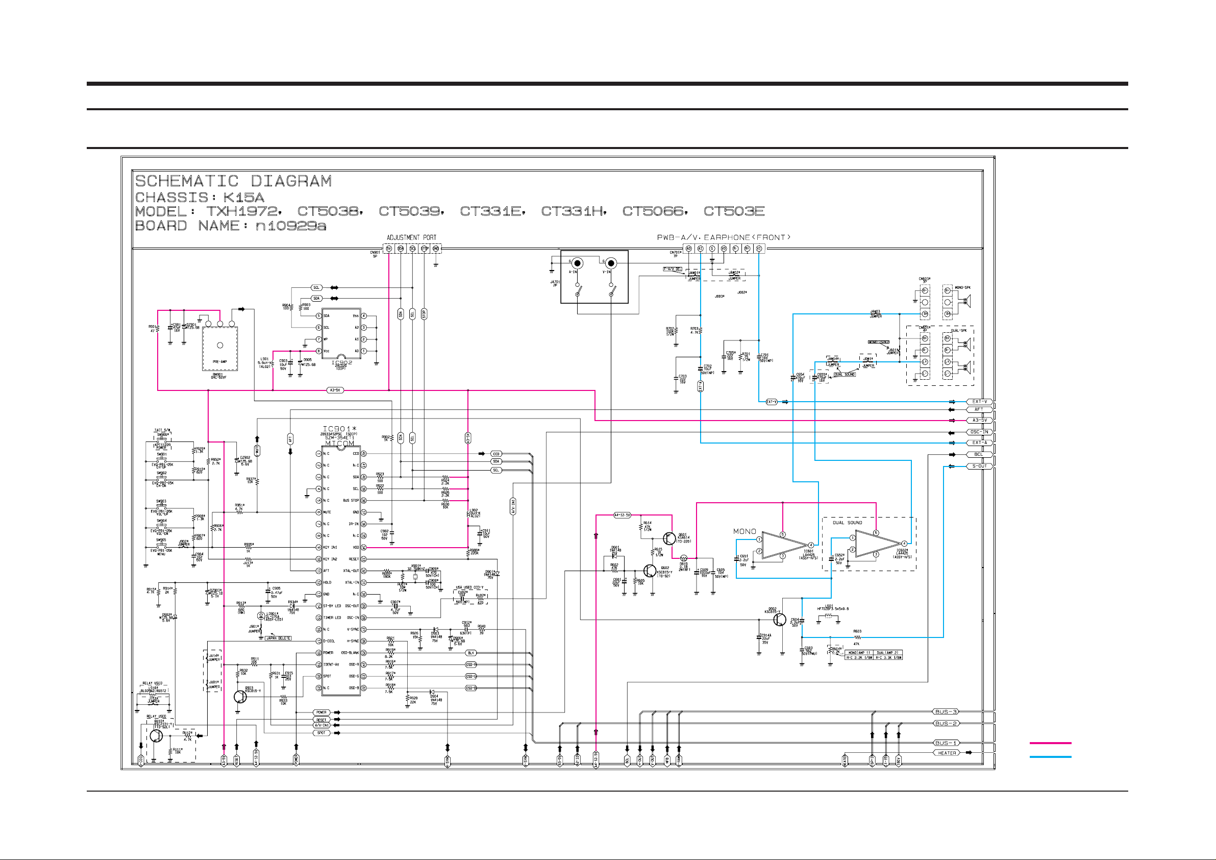
11. Schematic Diagrams
11-1 MAIN 1/4
Schematic Diagrams
Samsung Electronics 11-1
: Power Line
: Signal Line

TP13
IC201 30PIN
TP15
TP17
TP21
TP10
TP11
TP19
IC201 37PIN
IC201 43PIN
IC201 47PIN
IC201 53PIN
IC201 25PIN
IC201 27PIN
TP7
TP8
IC201 23PIN
IC201 22PIN
TP14
IC201 32PIN
TP16
TP18
TP12
TP20
IC201 41PIN
IC201 45PIN
IC201 49PIN
IC201 28PIN
TP9
IC201 24PIN
TP4
TP5
IC201 20PIN
IC201 19PIN
TP6
IC201 21PIN
TP1
TP2
IC201 4 PIN
IC201 2 PIN
TP3
IC201 7PIN
Schematic Diagrams
11-2 Samsung Electronics
TP9
TP10
TP13
TP14
TP15
TP16
TP17
TP18
TP21
TP19
TP20
TP1
TP2
TP3
TP4
TP5
TP6
TP7
TP8
TP11
TP12
11-2 MAIN 2/4
: Power Line
: Signal Line
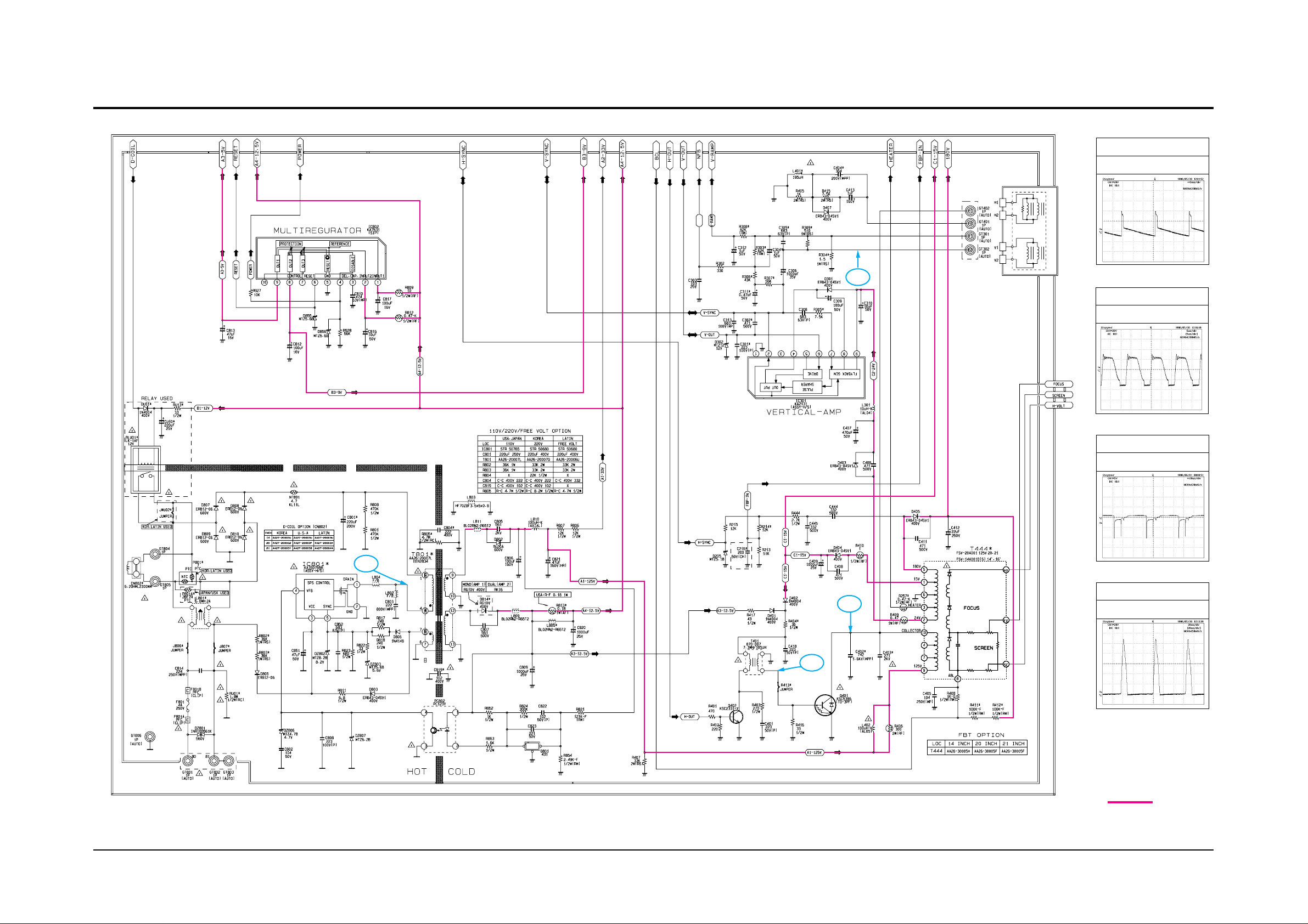
Schematic Diagrams
Samsung Electronics 11-3
TP25
TP27
TP26
TP24
11-3 MAIN 3/4
TP24
TP26
TP25
IC801 1 PIN
TP27
T444 10 PIN
: Power Line
Schematic Diagrams
11-4 Samsung Electronics
11-4 MAIN 4/4
: Power Line
: Signal Line

COLOR TELEVISION RECEIVER
Chassis : K15A
Model: CT331HBZX CT501EBZX
CT331EBZX CT501HX
CT331HBX CT5066BZX
CT331HX CT5038ZX
CT3366BZX
CT3338ZX
COLOR TELEVISION RECEIVER CONTENTS
Precautions
Specifications
Disassembly and Reassembly
Alignment and Adjustments
Troubleshooting
Exploded Views and Parts List
Electric Parts List
Block Diagram
PCB Layout
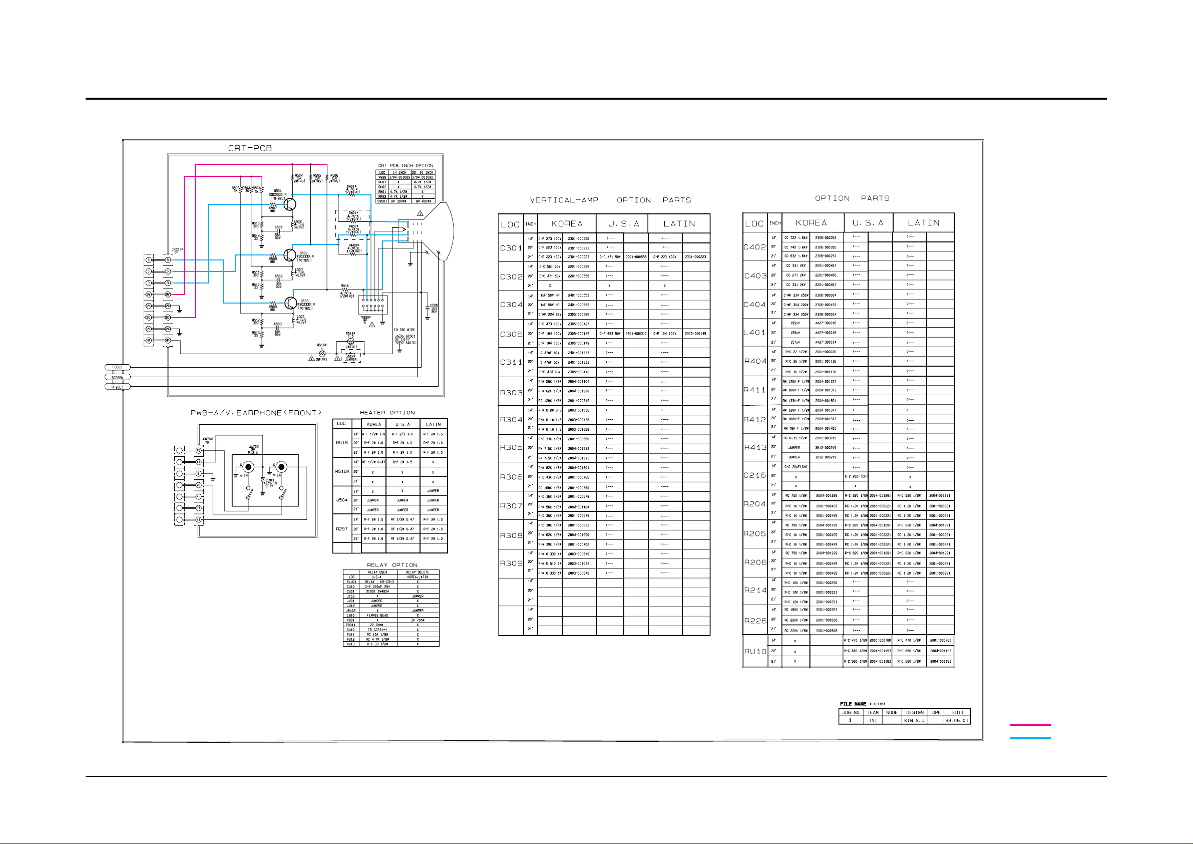
Wiring Diagrams
Schematic Diagrams
1.
2.
3.
4.
5.
6.
7.
8.
9.
10.
11.

ELECTRONICS
©
Samsung Electronics Co., Ltd. JUN. 1998
Printed in Korea
3K15A-0101

1. Precautions
1-1 Safety Precautions
1. Be sure that all of the built-in protective
devices are replaced. Restore any missing
protective shields.
2. When reinstalling the chassis and its
assemblies, be sure to restore all protective
devices, including: nonmetallic control knobs
and compartment covers.
3. Make sure that there are no cabinet openings
through which peopleÑparticularly
childrenÑmight insert fingers and contact
dangerous voltages. Such openings include
the spacing between the picture tube and the
cabinet mask, excessively wide cabinet
ventilation slots, and improperly fitted back
covers.
If the measured resistance is less than 1.0
megohm or greater than 5.2 megohms, an
abnormality exists that must be corrected
before the unit is returned to the customer.
4. Leakage Current Hot Check (Figure 1-1):
Warning: Do not use an isolation
transformer during this test. Use a leakagecurrent tester or a metering system that
complies with American National Standards
Institute (ANIS C101.1, Leakage Current for
Appliances), and Underwriters Laboratories
(UL Publication UL1410, 59.7).
5. With the unit completely reassembled, plug
the AC line cord directly into the power
outlet. With the unitÕs AC switch first in the
ON position and then OFF, measure the
current between a known earth ground (metal
water pipe, conduit, etc.) and all exposed
metal parts, including: antennas, handle
brackets, metal cabinets, screwheads and
control shafts. The current measured should
not exceed 0.5 milliamp. Reverse the powerplug prongs in the AC outlet and repeat the
test.
Fig. 1-1 AC Leakage Test
6. Antenna Cold Check:
With the unitÕs AC plug disconnected from the
AC source, connect an electrical jumper across
the two AC prongs. Connect one lead of the
ohmmeter to an AC prong. Connect the other
lead to the coaxial connector.
7. X-ray Limits:
The picture tube is especially designed to prohibit X-ray emissions. To ensure continued
X-ray protection, replace the picture tube only
with one that is the same type as the original.
Carefully reinstall the picture tube shields and
mounting hardware; these also provide X-ray
protection.
8. High Voltage Limits:
High voltage must be measured each time servicing is done on the B+, horizontal deflection
or high voltage circuits. Correct operation of
the X-ray protection circuits must be
reconfirmed whenever they are serviced.
(X-ray protection circuits also may be called
Òhorizontal disableÓ or Òhold-downÓ.)
Heed the high voltage limits. These include
the XÐray Protection Specifications Label, and
the Product Safety and X-ray Warning Note on
the service data schematic.
Precautions
Samsung Electronics 1-1
LEAKAGE
CURRENT
TESTER
DEVICE
UNDER
TEST
TEST ALL
EXPOSED METAL
SURFACES
2-WIRE CORD
ALSO TEST WITH
PLUG REVERSED
(USING AC ADAPTER
PLUG AS REQUIRED)
EARTH
GROUND
(READING SHOULD
NOT BE ABOVE
0.5mA)
Follow these safety, servicing and ESD precautions to prevent damage and protect against potential
hazards such as electrical shock and X-rays.

1-1 Safety Precautions (Continued)
9. High voltage is maintained within specified
limits by close-tolerance, safety-related
components and adjustments. If the high
voltage exceeds the specified limits, check
each of the special components.
10. Design Alteration Warning:
Never alter or add to the mechanical or
electrical design of this unit. Example: Do not
add auxiliary audio or video connectors. Such
alterations might create a safety hazard. Also,
any design changes or additions will void the
manufacturerÕs warranty.
11. Hot Chassis Warning:
Some TV receiver chassis are electrically
connected directly to one conductor of the AC
power cord. If an isolation transformer is not
used, these units may be safely serviced only
if the AC power plug is inserted so that the
chassis is connected to the ground side of the
AC source.
To confirm that the AC power plug is inserted
correctly, do the following: Using an AC
voltmeter, measure the voltage between the
chassis and a known earth ground. If the
reading is greater than 1.0V, remove the AC
power plug, reverse its polarity and reinsert.
Re-measure the voltage between the chassis
and ground.
12. Some TV chassis are designed to operate with
85 volts AC between chassis and ground,
regardless of the AC plug polarity. These units
can be safely serviced only if an isolation
transformer inserted between the receiver and
the power source.
13. Some TV chassis have a secondary ground
system in addition to the main chassis ground.
This secondary ground system is not
isolated from the AC power line. The two
ground systems are electrically separated by
insulating material that must not be defeated
or altered.
14. Components, parts and wiring that appear to
have overheated or that are otherwise
damaged should be replaced with parts that
meet the original specifications. Always
determine the cause of damage or overheating, and correct any potential hazards.
15. Observe the original lead dress, especially
near the following areas: Antenna wiring,
sharp edges, and especially the AC and high
voltage power supplies. Always inspect for
pinched, out-of-place, or frayed wiring. Do
not change the spacing between components
and the printed circuit board. Check the AC
power cord for damage. Make sure that leads
and components do not touch thermally hot
parts.
16. Picture Tube Implosion Warning:
The picture tube in this receiver employs
Òintegral implosionÓ protection. To ensure
continued implosion protection, make sure
that the replacement picture tube is the same
as the original.
17. Do not remove, install or handle the picture
tube without first putting on shatterproof
goggles equipped with side shields. Never
handle the picture tube by its neck. Some
Òin-lineÓ picture tubes are equipped with a
permanently attached deflection yoke; do not
try to remove such Òpermanently attachedÓ
yokes from the picture tube.
18. Product Safety Notice:
Some electrical and mechanical parts have
special safety-related characteristics which
might not be obvious from visual inspection.
These safety features and the protection they
give might be lost if the replacement component differs from the originalÑeven if the
replacement is rated for higher voltage,
wattage, etc.
Components that are critical for safety are
indicated in the circuit diagram by shading,
( ) or ( ).
Use replacement components that have the
same ratings, especially for flame resistance
and dielectric strength specifications.
A replacement part that does not have the
same safety characteristics as the original
might create shock, fire or other hazards.
Precautions
1-2 Samsung Electronics
!

1-2 Servicing Precautions
1. Servicing precautions are printed on the
cabinet. Follow them.
2. Always unplug the unitÕs AC power cord from
the AC power source before attempting to: (a)
Remove or reinstall any component or
assembly, (b) Disconnect an electrical plug or
connector, (c) Connect a test component in
parallel with an electrolytic capacitor.
3. Some components are raised above the printed
circuit board for safety. An insulation tube or
tape is sometimes used. The internal wiring is
sometimes clamped to prevent contact with
thermally hot components. Reinstall all such
elements to their original position.
4. After servicing, always check that the screws,
components and wiring have been correctly
reinstalled. Make sure that the portion around
the serviced part has not been damaged.
5. Check the insulation between the blades of the
AC plug and accessible conductive parts
(examples: metal panels, input terminals and
earphone jacks).
6. Insulation Checking Procedure: Disconnect the
power cord from the AC source and turn the
power switch ON. Connect an insulation
resistance meter (500V) to the blades of the AC
plug.
The insulation resistance between each blade
of the AC plug and accessible conductive parts
(see above) should be greater than 1 megohm.
7. Never defeat any of the B+ voltage interlocks.
Do not apply AC power to the unit (or any of
its assemblies) unless all solid-state heat sinks
are correctly installed.
8. Always connect a test instrumentÕs ground
lead to the instrument chassis ground before
connecting the positive lead; always remove
the instrumentÕs ground lead last.
Precautions
Samsung Electronics 1-3
Warning1: First read the “Safety Precautions” section of this manual. If some unforeseen circumstance creates a conflict between
the servicing and safety precautions, always follow the safety precautions.
Warning2: An electrolytic capacitor installed with the wrong polarity might explode.

1. Some semiconductor (Òsolid stateÓ) devices
are easily damaged by static electricity. Such
components are called Electrostatically
Sensitive Devices (ESDs); examples include
integrated circuits and some field-effect
transistors. The following techniques will
reduce the occurrence of component damage
caused by static electricity.
2. Immediately before handling any semicon
ductor components or assemblies, drain the
electrostatic charge from your body by
touching a known earth ground. Alternatively,
wear a discharging wrist-strap device. (Be
sure to remove it prior to applying powerÑ
this is an electric shock precaution.)
3. After removing an ESD-equipped assembly,
place it on a conductive surface such as
aluminum foil to prevent accumulation of
electrostatic charge.
4. Do not use freon-propelled chemicals. These
can generate electrical charges that damage
ESDs.
5. Use only a grounded-tip soldering iron when
soldering or unsoldering ESDs.
6. Use only an anti-static solder removal device.
Many solder removal devices are not rated as
Òanti-staticÓ; these can accumulate sufficient
electrical charge to damage ESDs.
7. Do not remove a replacement ESD from its
protective package until you are ready to
install it. Most replacement ESDs are
packaged with leads that are electrically
shorted together by conductive foam,
aluminum foil or other conductive materials.
8. Immediately before removing the protective
material from the leads of a replacement ESD,
touch the protective material to the chassis or
circuit assembly into which the device will be
installed.
9. Minimize body motions when handling
unpackaged replacement ESDs. Motions such
as brushing clothes together, or lifting a foot
from a carpeted floor can generate enough
static electricity to damage an ESD.
Precautions
1-4 Samsung Electronics
1-3 Precautions for Electrostatically Sensitive Devices (ESDs)
Specifications
Samsung Electronics 2-1
2. Specifications
2-1 Specifications
Television System 14"/20"/21" NTSC COLOR TV SIGNAL
Power Consumption 14" : 57 WATTS NOMINAL,
20" : 70 WATTS NOMINAL
21" : 75 WATTS NOMINAL,
Picture Tube 14" : A34KQV42X
20" : A48KRD82X (H)
21": : A51KQJ63X (H)
Power Requirement AC 120V, 60Hz /AC 100 ~ 240, 50Hz, 60Hz
Operating System REMOCON SYSTEM (SZM354ET)
Tuning Ranges VHF CH : 2-13, UHF CH : 14-69, CABLE CH : 1,14-125
Antenna Input Impedance 75 ohm UNBALANCED TYPE FOR VHF/UHF
Intermediate Frequency PICTURE 45.75MHz, SOUND 41.25MHz,
COLOR SUB CARRIER 42.17MHz
Speaker Impedance Single:
Dual : 8 ohm 3W x 2
Dual : 16 ohm , 3W x 2 (CT-33H1, CT-50H1)
8 ohm 3W
Disassembly and Reassembly
Samsung Electronics 3-1
3. Disassembly and Reassembly
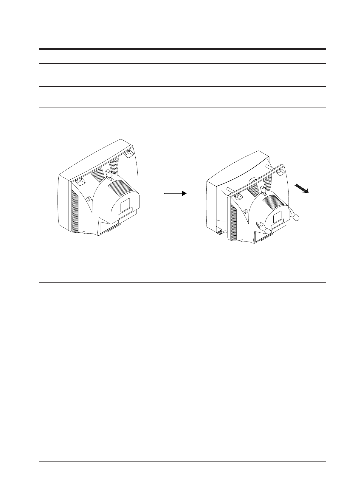
3-1 Back Cover Removeal
Fig. 3-1
1. After removing the screws, pull the cabinet backwards.

3-2 Main Board Removal
Disassembly and Reassembly
3-2 Samsung Electronics
Fig. 3-2
Fig. 3-3
1. Separate the socket board from the CRT neck.
2. Remove the Anode Cap from the CRT.
3. Remove the main board by pulling it with both hands.
Warning: The FBT is charged with high voltage.
Before removing the Anode Cap, discharge the voltage
through one of the heat sinks on the main board.
Disassembly and Reassembly
Samsung Electronics 3-3
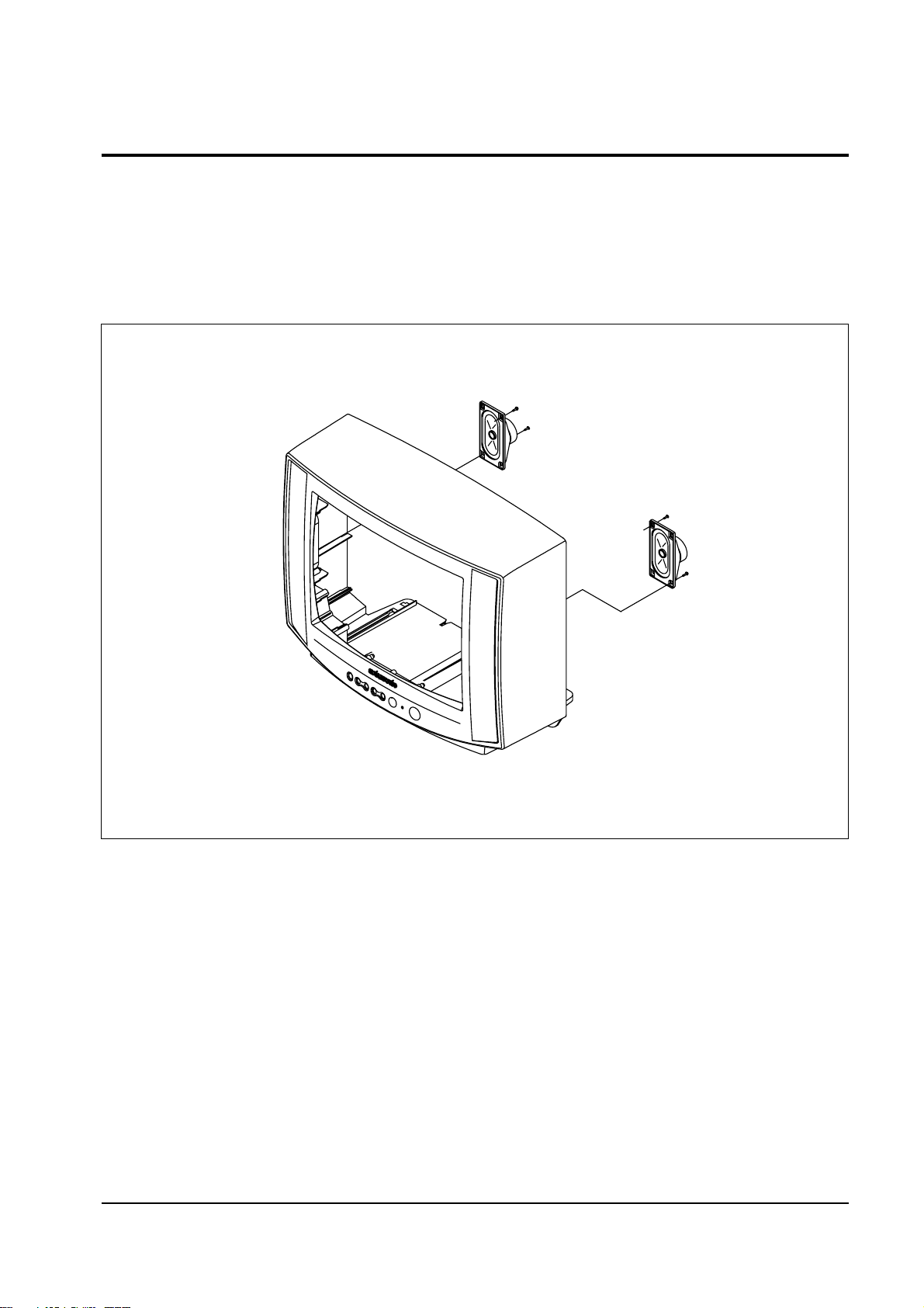
3-3 Speaker Removal
1. Loosen the screws and remove the speakers.
Fig. 3-4

Disassembly and Reassembly
3-4 Samsung Electronics
3-4 CRT Removel
Fig. 3-5
1. Spread a soft mat on the floor. Place the TV set face down.
2. Remove the 4 nuts mounting the CRT to the front cabinet.
3. Lift the CRT.
4. Caution: Because of the high vacuum and large surface area of the
picture tube, be careful while handling it:
(1) Always lift the picture tube by grasping it firmly around the faceplate, (2) Never lift the tube by its neck. (3) Do not scratch the picture
tube or apply excessive pressure. Fractures of the glass may cause an
implosion.
Alignment and Adjustments
Samsung Electronics 4-1
4. Alignment and Adjustments
4-1 Service Mode Adjustments
4-1-1 Service Mode Menus
Since there are no VRs in the K15A chassis, all
adjustments after parts replacement must be
done in the Service Mode. Service Mode
adjustments are necessary when either the
EEPROM (IC902) or the CRT is replaced.
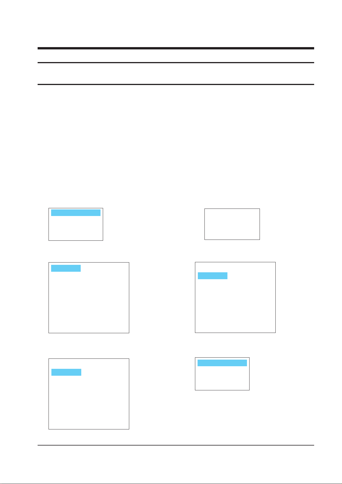
4-1-2 Entering the Service Mode
Press the following transmitter keys
while in STAND-BY mode:
MUTE—>1—>8—>2—>POWER
“Factory Mode Menu” is displayed
<---selected (violet)
RC XXX
VCO XX GC XXX
SBT XX BC XX
SCT XX VA XX
SCR XX VS XX
STT XXX HS XX
GG XXX SS XX
BG XXX SVC : MUTE
AGC XX
AGC XX RC XXX
GC XXX
SBT XX BC XX
SCT XX VA XX
SCR XX VS XX
STT XXX HS XX
GG XXX SS XX
BG XXX SVC : MUTE
VCO XX
VCO
71
AGC XX XXX
XXX
XX XX
XX VA XX
XX VS XX
XXX HS XX
XXX SS XX
XXX
SVC : MUTE
VCO XX
RC
GC
SBT
BC
SCT
SCR
STT
GG
BG
ADJUSTMENT
PATTERN
OPTION
RESET
ADJUSTMENT
PATTERN
OPTION
RESET
Enter Service Mode using the Volume
+,- keys. Service Mode Menu:
Return to the Service mode by pressing
MENU.
Change the data with “Volume +, - “ keys.
Return to the Factory mode via the MENU
key.
Press POWER to enter the Stand-by mode.
Select a mode to be adjusted, using the channel down key. Example: VCO.

POWER
OFF
No
Item Function
Range
MICOM Data
1 AGC RF AGC Adjustment 0~63 50
2 VCO PIF VCO Adjustment 0~127 63
3 SCT SUB-CONTRAST Adjustment 0~63 48
4 SCR SUB-COLOR Adjustment 0~27 13
5 STT SUB-TINT Adjustment 0~27 7
6 RC RED-CUT OFF Adjustment 0~255 0
7 GC GREEN-CUT OFF Adjustment 0~255 0
8 BC BLUE-CUT OFF Adjustment 0~255 0
9 SVC Input a Horiz line pattern
10 GG GREEN-GAIN Adjustment 0~255 127
11 BG BLUE-GAIN Adjustment 0~255 127
12 SBT SUB-BRIGHTNESS Adjustment 0~63 31
13 VA VERTICAL SIZE Adjustment 0~63 39
14 VS VERTICAL CENTER Adjustment 0 0
15 HS HORIZONTAL Phase Adjustment 0~31 15
16 SS SUB-SHARPNESS Adjustment 0~31 4
BYTE 0 : 0 0
ADJUSTMENT
PATTERN
OPTION
RESET
ADJUSTMENT
PATTERN
OPTION
RESET
ADJUSTMENT
PATTERN
OPTION
RESET
ADJUSTMENT
PATTERN
OPTION
RESET
ADJUSTMENT
PATTERN
OPTION
RESET
Initalized
Alignment and Adjustments
4-2 Samsung Electronics
4-1-3 Adjustment in Option Mode
This adjustment is necessary whenever the
EEPROM is replaced. Input data (as marked
on the back cabinet).
Select “SET OPTION” by pressing the
Channel key twice.
Press the Volume +, - keys to enter the set
Option mode.
Press MENU to go back to the factory mode.
Select RESET with channel key.
Press volume + key.
▼
▼
4-1-4 Service Mode Adjustments
1. The Pattern Adjustment is done only in the
factory. Do not attempt to readjust it.
2. Refer to 4-2 for other adjustments.
3. Set OPTION data.
4-1-5 Service Mode Adjustment Ratings
Note : The initial MICOM data values take
effect when IC902 is replaced.

Alignment and Adjustments
Samsung Electronics 4-3
4-2 Alignment and Adjustment
4-2-1 General Alignment Instructions
1. Usually, a color TV needs only slight
touch-up adjustment upon installation. Check
the basic characteristics such as picture height,
focus and a horizontal and vertical sync.
2. Observe the picture and check for good back
and white details. There should be no
objectionable color shading: If color shading is
present, demagnetize the receiver. If color
shading persists, perform purity and
convergence adjustments described below.
3. To protect against shock hazard, use an
isolation transformer.
4-2-2 Power Supply Check
Check the following:
A: Power plug is connected; “Stand-by” mode
B: Power On when “Power ON” button is pressed
C: Power On by FBT Each supply is marked on
its lead-in wire. ( )
4-2-3 Focus Adjustment
Adjust the focus control on the FBT for well
defined scanning lines.
4-2-4 Fail Safe Circuit Check (FS) (OPTION)
1. The failsafe check must be the final step in
servicing.
2. Turn the power switch ON and adjust
customer controls for normal operation.
3. Temporarily short pin X to pin R on the main
board (RX06, RX04) with a jumper wire.
Raster will disappear.
4. The TV must remain in this state even after
removing the jumper wire. This shows that
the failsafe circuit is working properly.
5. To recover picture and sound, temporarily
turn off the TV and allow the failsafe circuit
more than 30 seconds to reset. Then switch
power ON to produce normal picture and
sound.
4-2-5 IC902 Replacement
1. When IC902 is replaced, all values are reset to
“Initialized MICOM Data” and readjustment
is necessary.
2. Press the POWER button 10 seconds after
plug-in.
3. To enter the Service Mode, refer to Fig. 4-1
(Service Mode Adjustment).
4-2-6 PIF VCO Adjustment
1. Use a Pattern Generator or an off-air signal.
2. Open pin 11 of Micom (IC901) or one side of
lead pin for R237.
3. Adjust VCO in the service mode to set IC101
Pin 44 (AFT) to 2.5V ± 0.4V.
4. Connect the opened site.
4-2-7 RF-AGC Adjustment
1. Input a PHILLIPS pattern.
2. Set the input signal to 60 dB.
3. Enter into the AGC in the service mode.
4. Adjust AGC until color bar noise disappears.
 Loading...