

SAMSUNG CT3338FX-XAP, CT5038FX-XAP, CT2088BLFX-XAP, CT20D8BWFX-XAP Service Manual
COLOR TELEVISION RECEIVER
Chassis : K15D
Model : CT3338FX/XAP
CT5038FX/XAP
CT2088BLFX/XAP
CT20D8BWFX/XAP
COLOR TELEVISION RECEIVER CONTENTS
Precautions
Specifications and IC Data
Disassembly and Reassembly
Alignment and Adjustment
Troubleshooting
Exploded View and Parts List
Electrical Parts List
Block Diagram
Wiring Diagram
Schematic Diagrams
1.
2.
3.
4.
5.
6.
7.
8.
9.
10.

ELECTRONICS
© Samsung Electronics Co., Ltd. SEP. 2002
Printed in Korea
AA82-00154A

Alignment and Adjustments
Samsung Electronics 4-1
4. Alignment and Adjustments
4-1 Preadjustment
4-1-1 Factory Mode
1. Do not attempt these adjustments in the Video
Mode.
2. The Factory Mode adjustments are necessary
when either the EEPROM (IC902) or the CRT
is replaced.
3. Do not tamper with the “Adjustment” screen
of the Factory Mode menu. This screen is
intended only for factory use.
4-1-2 When EEPROM (IC902) Is Replaced
1. When IC902 is replaced all adjustment data
revert to initial values. It is necessary to
re-program this data.
2. After IC902 is replaced, warm up the TV for
10 seconds.
4-1-3 When CRT Is Replaced
1. Make the following adjustments AFTER setting up after setting up purity and convergence :
White Balance
Sub-Brightness
Vertical Center
Vertical Size
Horizontal Size
Fail Safe (This adjustment must be the last
step).
2. If the EEPROM or CRT is replaced and set SC
as 20(factory mode).
4-2 Factory/Service Mode
4-2-1 Procedure for the “Adjustment” Mode
1. This mode uses the standard remote control.
The Service Mode is activated by entering the
following remote-control sequence :
(1) DISPLAY → FACTORY.
(2) STAND-BY → MUTE → 1 → 8 → 2
→POWER ON.
2. The “SERVICE (FACTORY)” message will be
displayed. The Service Mode has four components: ADJUST, OPTION , G2-ADJUST and
RESET.
3. Access the Adjustment Mode by pressing the
“VOLUME” keys ( Up or Down). The adjustment parameters are listed in the accompanying table, and selected by pressing the CHANNEL keys ( , ).
4. Selection sequences for the all system:
DOWN or UP key:
SCT>SBT>BLR>BLB>RG>GG>BG>VSL>VS>
VA>HS>SC>CDL>STT>AKB>FS>NDL>
LBS>NSR>SCBT>VOL>CAP>HBS>RP00>
RP01>FMWS>AGC1>OMD>SCL>PWL>
MUS>AGC>DSK>DVDB
5. The VOLUME keys increase or decrease the
adjustment values (stored in the
non-volatile memory) when Adjustment Mode
is cancelled.
6. Cancel the Adjustment Mode by re-pressing
the “FACTORY” or “Power OFF” keys.
4-2-2 Main Adjustment Parameter
Alignment and Adjustments
4-2 Samsung Electronics
OSDNO FUNCTION RANGE INITAL DATA
1
SCT Sub Cont ras t 0 ~ 23
2
SBT Sub Bright nes s
3
4
5
6
7
8
9
10
11
12
13
14
15
16
17
18
19
SCBT Screen Brighrtness 0 ~ 63
20
21
22
23
RP00
24
RP01
25
FMWS
26
AGC1
27
OMD
28
29
30
31
32
33
34
Black Level offset Red
BLR
Black Level offset Blue
BLB
RG Red Ga in 0 ~ 63
GG Green Gain 0 ~ 63
BG Blue Gai n 0 ~ 63
VSL Vert ical Slope 0 ~ 63
VS Ver t ical Shi f t 0 ~ 63
VA Vert ical Ampli tud e 0 ~ 63
HS Horizont al Shif t 0 ~ 63
SC S- Cor r ec t i on 0 ~ 63
CDL Cathode Drive Level 0 ~ 15
STT Sub Tint 0 ~ 7
AKBFSAKB On / off 0 ~ 1
Filter Seting
NDL NTSC Delay 0 ~ 15
Low Band Separation Set
LBS
NSR NTSC Sub color 0 ~ 23
VOL Volume pre set t i ng 0 ~ 63
CAP Caption Position
HBS
High Band Separation Set
Ratio Pre / overshoot
Ratio Pre / overshoot
Window Selection Sound PLL
IF AGC Speed
Offset IF Demodulator
SCL
Soft Clipping Level
PWL
Peak White Limitting
MUS
Matrix USA
AGC
Automatic Gain Control
DSK
Dynamic Skin Tone
DVDB
DVD Bright Offset
0~23
0~63
0~63
0~15
0~63
0~15
0~63
0~1
0~1
0~1
0~3
0~63
0~3
0~15
0~1
0~63
0~1
00~1
SETTING
19V 13V
15
8
35
32
40
30
42
30
31
20
32
35
11
3
0
32
1
32
3
35
10
12
32
1
1
0
1
32
3
15
0
33
0
5
13
9
31
27
32
25
31
31
31
40
30
20
11
7
0
37
1
32
3
45
10
12
32
1
1
0
1
32
1
13
0
33
0
4
13
9
31
27
32
25
31
31
31
20
30
12
7
7
0
37
1
32
3
45
10
12
32
1
1
0
1
32
1
13
0
33
0
4
REMARK
W/B (HIGH Y)
W/B A (LOW Y)
W/B (LOW X, Y)
W/B (LOW X, Y)
W/B (HIGH X, Y)
FIX
W/B (HIGH X, Y)
Vertical SLOPE
FIX
Vertical SIZE
Horizontal SHIFT
FIX
FIX
FIX
FIX
FIX(STEREO)
FIX
FIX(STEREO)
FIX
FIX
FIX
FIX
FIX(STEREO)
FIX
FIX
FIX (Mono)
FIX (Nomal)
FIX (No Crrection)
FIX (Off)
FIX (100%)
FIX (Mono)
FIX
FIX
FIX

Alignment and Adjustments
Samsung Electronics 4-3
4-2-3 Option Bytes
In the Service Mode, various can be selected via the Option Table. Example:
Option Table : xx xx
OSD
1
2
3
4
5
6
VIDEO MUTE
(When swiching channel)
AUDIO
TURBO
ZOOM
AUTO POWER ON
SOUND MUTE
(NO SIGNAL)
SETTING
ON
OFF
STEREO
LINE STEREO
MONO
ON
OFF
ZOOM
NOMAL
ON
OFF
OFF
ON
REMARK
- 800msec Mute Time(Tri-norma)
- Unavailable
- Zenith stereo (WITH IN UPC1851B)
- Line stereo (WITH IN UPC1851B)
- Mono (WITH OUT UPC1851B)
- Stereo/L STEREO Model
- Mono Model
- Nornal / Zoom
- Nomal
- The power is switched on automatically
when detaching the Master S/W Auto On
- Tact S/W Model
- Unavailable
- Available
ENGLISH
7
8
9
10
11
12
13
LANGUAGE
HOTEL MODE
CATV
X-RAY
V-CHIP
AV Option
DEMO
ESPANOL
FRENCH/PORTU
OFF
ON
AIR/STD/HRC/IRC
AIR/STD/HRC/AFN
ON
OFF
ON
OFF
TV ↔ AV
TV ↔ AV ↔ DVD
ON
OFF
- Start Language Select
- Unavailable
- Available
- U.S Army
- Available (U.S.A, Army)
- Unavailable (South America)
- Available (U.S.A)
- Unavailable (Canada)
- Available (South America)
- Unavailable (U.S.A)

Alignment and Adjustments
4-4 Samsung Electronics
4-3 Other Adjustments
4-3-1 General
1. Usually, a color TV needs only slight touchup adjustment upon installation. Check the
basic characteristics such as height, horizontal
and vertical sync and focus.
2. The picture should have good black and white
details. There should be no objectionable
color shading; if color shading is present, perform the purity and convergence adjustments
described below.
3. Use the specified test equipment or its equivalent.
4. Correct impedance matching is essential.
5. Avoid overload. Excessive signal from a sweep
generator might overload the front-end of the
TV. When inserting signal markers, do not
allow the marker generator to distort test
results.
6. Connect the TV only to an AC power source
with voltage and frequency as specified on the
backcover nameplate.
7. Do not attempt to connect or disconnect any
wires while the TV is turned on. Make sure
that the power cord is disconnected before
replacing any parts.
8. To protect against shock hazard, use an isolation transformer.
4-3-2 Automatic Degaussing
A degaussing coil is mounted around the picture tube, so that external degaussing after
moving the TV should be unnecessary. But
the receiver must be properly degaussed upon
installation.
The degaussing coil operates for about 1 second after the power is switched ON. If the set
has been moved or turned in a different direction, disconnect its AC power for at least 30
minutes.
If the chassis or parts of the cabinet become
magnetized, poor color purity will result. If
this happens, use an external degaussing coil.
Slowly move the degaussing coil around the
faceplate of the picture tube and the sides and
front of the receiver. Slowly withdraw the coil
to a distance of about 6 feet before removing
power.

Alignment and Adjustments
Samsung Electronics 4-5
4-3-3 High Voltage Check
CAUTION: There is no high voltage adjustment on this chassis.
The B+ power supply must be set to +122.5 volts (Full color bar
input and normal picture level).
1. Connect a digital voltmeter to the second
anode of the picture tube.
2. Turn on the TV. Set the Brightness and
Contrast controls to minimum (zero beam current).
3. The high voltage should not exceed 30KV.
4. Adjust the Brightness and contrast controls to
both extremes. Ensure that the high voltage
does not exceed 30KV under any conditions.
4-3-4 FOCUS Adjustment
1. Input a black and white signal.
2. Adjust the tuning control for the clearest pic-
ture.
3. Adjust the FOCUS control for well defined
scanning lines in the center area of the screen.
4-3-5 Cathode Voltage Adjustment
(Screen Adjustment)
1. Connect CRT socket pin GK to an oscilloscope
probe.
2. Input a gray scale pattern. (Use a pattern gen-
erator, PM5518)
3. Use the P mode key (on the remote control)
for the STANDARD picture.
4. Adjust the Screen VR (on the FBT) so that the
voltage on the oscilloscope becomes 125+2.5V
(See Fig. 4-1).
4-3-6 Purity Adjustment
1. Warm up the receiver for at least 20 minutes.
2. Plug in the CRT deflection yoke and tighten
the clamp screw.
3. Plug the convergence yoke into the CRT and
set in as shown in Fig. 4-2.
4. Input a black and white signal.
5. Fully demagnetize the receiver by applying an
external degaussing coil.
6. Turn the CONTRAST and BRIGHTNESS controls to maximum.
7. Loosen the clamp screw holding the yoke.
Slide the yoke backward or forward to provide vertical green belt. (Fig. 4-3).
8. Tighten the convergence yoke.
9. Slowly move the deflection yoke forward,
and adjust for the best overall green screen.
10. Temporarily tighten the deflection yoke.
11. Produce blue and red rasters by adjusting the
low-light controls. Check for good purity in
each field.
12. Tighten the deflection yoke.
Fig. 4-1
_
_
+
125 2.5V
GND

Alignment and Adjustments
4-6 Samsung Electronics
4-3-7 White Balance Adjustment
Fig. 4-2 Convergence Magnet Assembly
Fig. 4-3 Center Convergence Adjustment
Fig. 4-4
(a) Set up
1. Warm up the TV for at least 30 minutes in the
Aging Mode (OSD White). This mode is displayed by entering the following sequence:
DISPLAY
→FACTORY → FACTORY
2. Input a Toshiba pattern.
(b) Low-Light Adjustment
1. Set SBT to 1.2 fL in the Factory Service
Mode with using CA100. See Fig. 4-4.
2. Adjust RG,BG so that the levels are suitable to
each local area.
(c) High-Light Adjustment
1. Set SCT to 50FL(13V : 60FL) in the Factory
Service Mode with using CA100.
See Fig. 4-4 .
Clamper
6 Pole Magnet
Screw
4 Pole Magnet
2 Pole Magnet
2 POLE
PURITY
4 POLE
CONVERGENCE
Vertical Green Belt
YOKE
CLAMP
SCREW
6 POLE
CONVERGENCE
ADJU
(VERT
31m/m
1
2
Alignment and Adjustments
Samsung Electronics 4-7
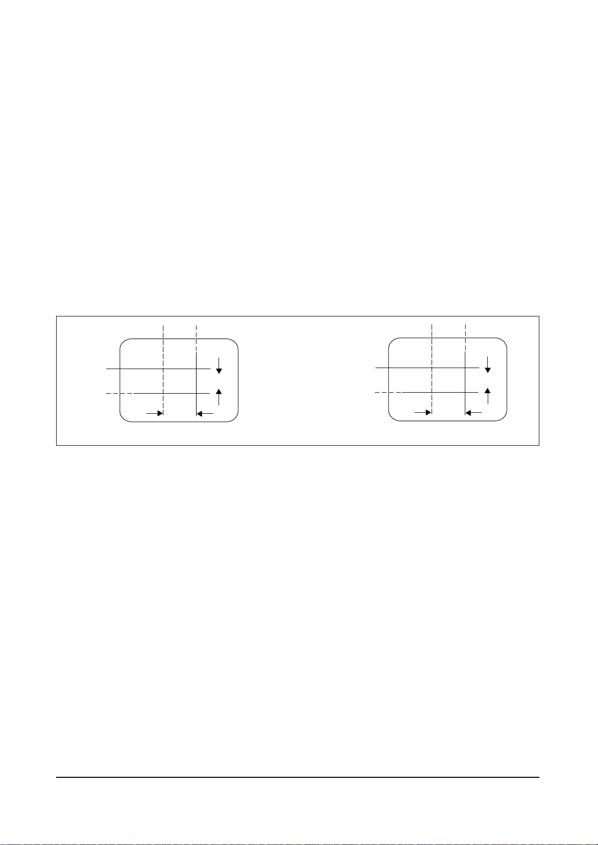
4-3-8 Center Convergence Adjustment
1. Warm up the receiver for at least 20 minutes.
2. Adjust the two tabs of the 4 pole magnets to
change the angle between them. Superimpose
the red and blue vertical lines in the center
area of the screen.
3. Adjust the Brightness and Contrast controls
for a well defined picture.
4. Adjust the two-tab pairs of the 4 pole magnets, and change the angle between them.
Superimpose the red and the blue vertical
lines in the center area of the screen.
5. Turn the both tabs at the same time, keeping
the angle constant, and superimpose the red
and blue horizontal line in the center of the
screen.
6. Adjust the two-tab pairs of the 6-pole magnets
to superimpose the red and blue line onto the
green. (Changing the angle affects the vertical
lines, and rotating both magnets affects the
horizontal lines.)
7. Repeat adjustments 2~6, if necessary.
8. Since the 4-pole magnets and 6-pole magnets
interact, the dot movement is complex
(Fig. 4-5).
Fig. 4-5 Center Convergence Adjustment
BLUE
BLUE
RED
RED
RED/BLUE
RED/BLUE
GREEN
GREEN
4-Pole Magnet Movement
6-Pole Magnet Movement
4-3-9 RF AGC Adjustment
Set the AGC data to 33 (Factory Mode).
4-3-10 Sub-Color Adjustment
Set NSR data to 3 (Factory Mode).
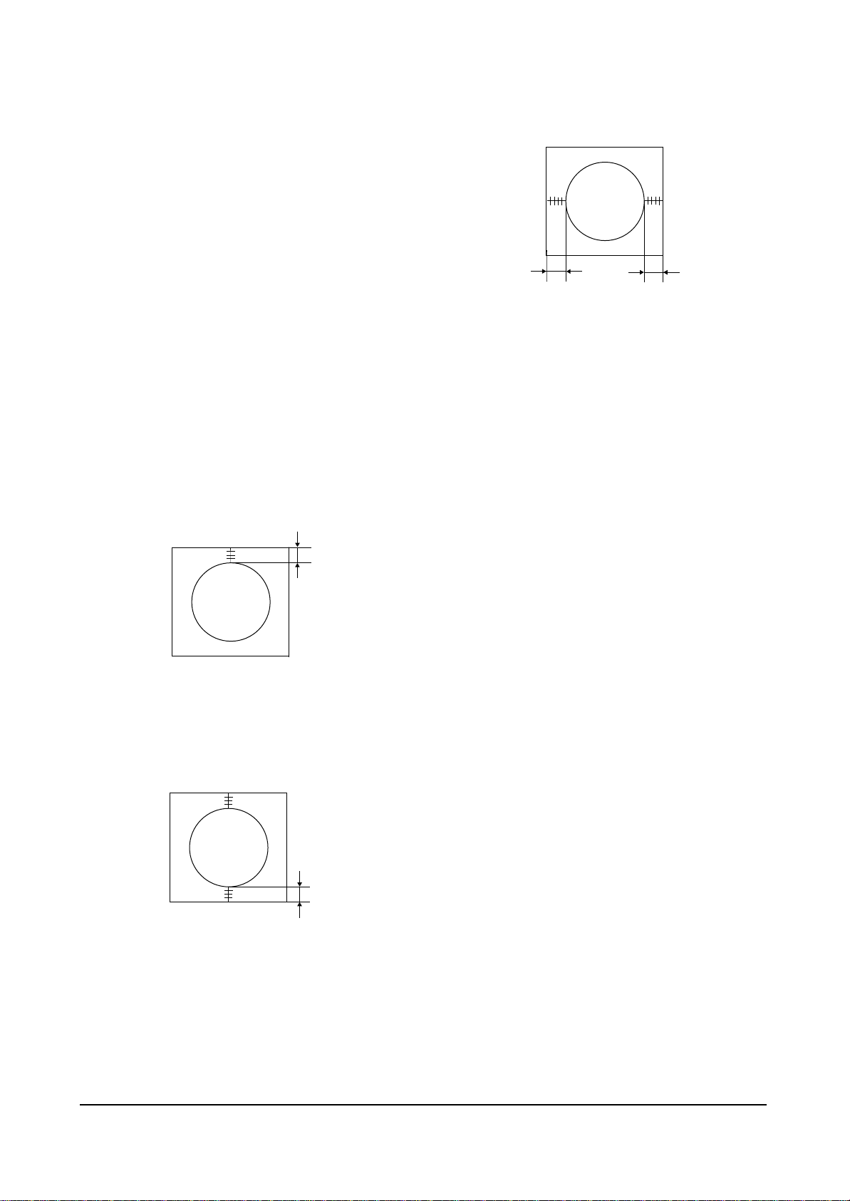
4-3-11 Geometry Adjustment
SC →VS→VA→VSL→HS
1. Input a lion head pattern.
2. Set the SC (S-Correction) as 20(13V : 12) and
VS(Vertical Shift) 31 so that the lion head circle
becomes oval.
3. Adjust with VA (Vertical Amplitude) so that
the top margin of the picture is 4.
Fig. 4-7
4. Adjust with VSL (Vertical-Slope) so that the
bottom margin of the picture is 4.
Fig. 4-8
5. Adjust with HS (Horizontal Shift) so that the
lion-head pattern and CRT centers are aligned.
Fig. 4-9
6. Adjust HS (Horizontal Shift) so that the left
and right margins of the picture are 5.
Alignment and Adjustments
4-8 Samsung Electronics
4
5
5
4

6. Exploded View & Parts List
6-1 CT3338FX/XAP
Exploded View & Parts List
Samsung Electronics 6-1
1 AA64-31147Q CABINET FRONT;3338,SV704P EPPV,HIPS,HB,G 1 F/C
1-1 INLAY-A/V
1-2 AA64-70127F BADGE-BRAND;AL,SS,SILVER,R800 1 BADGE
1-3 AA64-40057A WINDOW-REMOCON;-,ABS,HB,-,-,33 1 WR
1-4 AA64-10153J KNOB POWER;3338,ABS,-,G3676,NO-SILK,HB,- 1 KP
1-5 AA61-60003J SPRING-CS;-,-,SUS304,0.5,OD6,H 1 SPRING
1-6 6003-001026 SCREW-TAPTITE;RH,+,B,M4,L15,ZPC(BLK),SWR 1 KC+CF
1-7 AA64-10052B KNOB-CONTROL;-,3338,G3676 JPN,ABS,HB,GRA 1 KC
1-8 AA96-00144A ASSY-SPEAKER;-,8OHM,2.5WX2,3001-000281,A 1 A/SPK
1-9 AA61-40010A BOSS-CABINET;-,HIPS,HB,BLK, 2 BOSS
2 AA03-10002M CRT-COLOR;-,A34KQV42X,0MG,14, 1 CRT
2-1 AA61-00735A HOLDER;20POLYVINIL,DEGAUSSING,CHLORI 2 CDCOIL
2-2 AA60-10050Q SCREW-ASSY;WC,HH,M5,L26.5,SWRCH, 4 CRT+CF
3 AA64-00170A CABINET-BACK;,HIPS,HB,G4309 1 B/C
3-1 AA42-00004A ANT ROD;VHF,4SDODIPOLE850MMBRN 1 A/ROD
3-2 6003-001026 SCREW-TAPTITE;RH,+,B,M4,L15,ZPC(BLK),SWR 4 CB+CF
4 AA96-00669A ASSY POWER CORD;,CP2 N/P,H/C250,AA61-200 1 PWR/AC
No Code No Description;Specification Q’ty Remark
1-8
1-7
2-1
2-2
3-1
3
3-2
2
4
1-6
1-5
1-1
1-2
1-3
1-4
 Loading...