

Page 1

Owner’s
Instructions
COLOR TELEVISION
...........................................................................................................................
.............
AA68-03465A-00
CT29M16MQU
CT25M20MQU
CT29M20MQU
CT21T20MQU
AA68-03465A-00Eng_XTC_cover 5/7/04 1:29 PM Page 1
Page 2

2
Important Warranty Information
Regarding Television Format
Viewing
Standard screen format televisions (4:3, the aspect ratio of the screen width to height) are
primarily designed to view standard format full-motion video. The images displayed on
them should primarily be in the standard 4:3 ratio format and constantly moving.
Displaying stationary graphics and images on screen, such as the dark top and bottom
letterbox bars (wide screen pictures), should be limited to no more than 15% of the total
television viewing per week.
Wide screen format televisions (16:9, the aspect ratio of the screen width to height) are
primarily designed to view wide screen format full-motion video. The images displayed
on them should primarily be in the wide screen 16:9 ratio format, or expanded to fill the
screen if your model offers this feature, and constantly moving. Displaying stationary
graphics and images on screen, such as the dark side-bars on non-expanded standard
format television video and programming, should be limited to no more than 15% of the
total television viewing per week.
Additionally, viewing other stationary images and text such as stock market reports,
video game displays, station logos, web sites or computer graphics and patterns, should
be limited as described above for all televisions. Displaying any stationary images that
exceed the above guidelines can cause uneven aging of picture tubes (CRTs) that leave subtle,
but permanent burned-in ghost images in the television picture. To avoid this, vary the programming
and images, and primarily display full screen moving images, not stationary patterns or
dark bars. On television models that offer picture sizing features, use these controls to
view the different formats as a full screen picture.
Be careful in the selection and duration of television formats used for viewing. Uneven
CRT aging as a result of format selection and use, as well as other burned-in images, is
not covered by your Samsung limited warranty.
AA68-03465A-00Eng_XTC 5/7/04 1:30 PM Page 2
Page 3

CONTENTS
3
Chapter 1: Your New TV . . . . . . . . . . . . . . . . 5
List of Features . . . . . . . . . . . . . . . . . . . . . . . . . . . . . . . . . . . . . . . . . . . 5
Familiarizing Yourself with The TV . . . . . . . . . . . . . . . . . . . . . . . . . . . . 6
Front Panel Buttons . . . . . . . . . . . . . . . . . . . . . . . . . . . . . . . . 6
Side Panel Jacks . . . . . . . . . . . . . . . . . . . . . . . . . . . . . . . . . . . 6
Rear Panel Jacks . . . . . . . . . . . . . . . . . . . . . . . . . . . . . . . . . . . 7
Remote Control. . . . . . . . . . . . . . . . . . . . . . . . . . . . . . . . . . . . 8
Chapter 2: Installation . . . . . . . . . . . . . . . . . . 9
Connecting VHF and UHF Antennas . . . . . . . . . . . . . . . . . . . . . . . . . . 9
Antennas with 300-ohm Flat Twin Leads . . . . . . . . . . . . . . . . 9
Antennas with 75-ohm Round Leads . . . . . . . . . . . . . . . . . . 10
Separate VHF and UHF Antennas. . . . . . . . . . . . . . . . . . . . . 10
Connecting Cable TV . . . . . . . . . . . . . . . . . . . . . . . . . . . . . . . . . . . . . 10
Cable without a Cable Box . . . . . . . . . . . . . . . . . . . . . . . . . . 10
Connecting to a Cable Box that Descrambles All Channels . . 11
Connecting to a Cable Box that Descrambles Some Channels11
Connecting a VCR. . . . . . . . . . . . . . . . . . . . . . . . . . . . . . . . . . . . . . . . 12
Connecting an S-VHS VCR. . . . . . . . . . . . . . . . . . . . . . . . . . 14
Connecting a Second VCR to Record from the TV. . . . . . . . . 15
Connecting a DVD Player . . . . . . . . . . . . . . . . . . . . . . . . . . . . . . . . . . 15
Connecting a Camcorder. . . . . . . . . . . . . . . . . . . . . . . . . . . . . . . . . . . 16
Installing Batteries in the Remote Control. . . . . . . . . . . . . . . . . . . . . . 17
Chapter 3: Operation . . . . . . . . . . . . . . . . . . 18
Turning the TV On and Off. . . . . . . . . . . . . . . . . . . . . . . . . . . . . . . . . 18
Plug & Play Feature . . . . . . . . . . . . . . . . . . . . . . . . . . . . . . . . . . . . . . 18
Viewing the Menus and On-Screen Displays. . . . . . . . . . . . . . . . . . . . 20
Viewing the Menus. . . . . . . . . . . . . . . . . . . . . . . . . . . . . . . . 20
Viewing the Display . . . . . . . . . . . . . . . . . . . . . . . . . . . . . . . 20
Selecting a Menu Language. . . . . . . . . . . . . . . . . . . . . . . . . . . . . . . . . 21
Memorizing the Channels . . . . . . . . . . . . . . . . . . . . . . . . . . . . . . . . . . 22
Selecting the Video Signal-source . . . . . . . . . . . . . . . . . . . . . 22
Storing Channels in Memory (Automatic Method) . . . . . . . . 23
Adding and Erasing Channels (Manual Method). . . . . . . . . . 24
Changing Channels. . . . . . . . . . . . . . . . . . . . . . . . . . . . . . . . . . . . . . . 25
Using the Channel Buttons . . . . . . . . . . . . . . . . . . . . . . . . . . 25
Directly Accessing Channels . . . . . . . . . . . . . . . . . . . . . . . . . 25
Using the PRE-CH Button to select the Previous Channel. . . 25
Labeling the Channels. . . . . . . . . . . . . . . . . . . . . . . . . . . . . . . . . . . . . 26
Adjusting the Volume . . . . . . . . . . . . . . . . . . . . . . . . . . . . . . . . . . . . . 27
Using the Mute Button . . . . . . . . . . . . . . . . . . . . . . . . . . . . . 27
Setting the Clock. . . . . . . . . . . . . . . . . . . . . . . . . . . . . . . . . . . . . . . . . 28
Customizing the Picture . . . . . . . . . . . . . . . . . . . . . . . . . . . . . . . . . . . 29
Using Automatic Picture Settings . . . . . . . . . . . . . . . . . . . . . . . . . . . . 30
Customizing the Sound. . . . . . . . . . . . . . . . . . . . . . . . . . . . . . . . . . . . 31
Using Automatic Sound Settings. . . . . . . . . . . . . . . . . . . . . . . . . . . . . 32
Setting the Blue Screen Mode . . . . . . . . . . . . . . . . . . . . . . . . . . . . . . . 33
Setting The On/Off Melody. . . . . . . . . . . . . . . . . . . . . . . . . . . . . . . . . 34
Viewing an External Signal Source . . . . . . . . . . . . . . . . . . . . . . . . . . . 35
Setting the Signal Source. . . . . . . . . . . . . . . . . . . . . . . . . . . . 37
Assigning Names to External input mode . . . . . . . . . . . . . . . 36
AA68-03465A-00Eng_XTC 5/7/04 1:30 PM Page 3
Page 4

CONTENTS
4
Chapter 4: Special Features. . . . . . . . . . . . . 37
Changing the Color Tone . . . . . . . . . . . . . . . . . . . . . . . . . . . . . . . . . . 37
Changing the Screen Size . . . . . . . . . . . . . . . . . . . . . . . . . . . . . . . . . . 38
Digital Noise Reduction . . . . . . . . . . . . . . . . . . . . . . . . . . . . . . . . . . . 39
DNIe JrTM(Digital Natural Image engine) . . . . . . . . . . . . . . . . . . 40
Tilt . . . . . . . . . . . . . . . . . . . . . . . . . . . . . . . . . . . . . . . . . . . . . . . . . . . 41
Using the R.Surf Feature . . . . . . . . . . . . . . . . . . . . . . . . . . . . . . . . . . . 42
Choosing a Multi-Channel Sound (MTS) Soundtrack . . . . . . . . . . . . . 43
Extra sound settings (Auto Volume, Turbo Sound or Pseudo Stereo). . 44
Setting the On/Off Timer. . . . . . . . . . . . . . . . . . . . . . . . . . . . . . . . . . . 45
Setting the Sleep Timer. . . . . . . . . . . . . . . . . . . . . . . . . . . . . . . . . . . . 46
Setting the Preferred Volume Level . . . . . . . . . . . . . . . . . . . . . . . . . . . 47
Viewing Closed Captions . . . . . . . . . . . . . . . . . . . . . . . . . . . . . . . . . . 48
Viewing the Demonstration. . . . . . . . . . . . . . . . . . . . . . . . . . . . . . . . . 49
Chapter 5: Troubleshooting . . . . . . . . . . . . . 50
Identifying Problems. . . . . . . . . . . . . . . . . . . . . . . . . . . . . . . . . . . . . . 50
Appendix . . . . . . . . . . . . . . . . . . . . . . . . . . . . 51
Cleaning and Maintaining Your TV . . . . . . . . . . . . . . . . . . . . . . . . . . . 51
Using Your TV in Another Country. . . . . . . . . . . . . . . . . . . . . . . . . . . 51
Specifications . . . . . . . . . . . . . . . . . . . . . . . . . . . . . . . . . . . . . . . . . . . 51
AA68-03465A-00Eng_XTC 5/7/04 1:30 PM Page 4
Page 5

YOUR NEW TV
5
Chapter One
YOUR NEW TV
List of Features
Your TV was designed with the latest technology. This TV is a high-performance unit that
includes the following special features:
• Full Flat Screen
• Easy-to-use remote control
• Easy-to-use on-screen menu system
• Automatic timer to turn the TV on and off
• Adjustable picture and sound settings that can be stored in the TV’s memory
• Automatic channel tuning for up to 181 channels
• A special filter to reduce or eliminate reception problems
• A built-in multi-channel sound decoder for stereo and bilingual listening
• Built-in, dual channel speakers
• A special sleep timer
AA68-03465A-00Eng_XTC 5/7/04 1:30 PM Page 5
Page 6
YOUR NEW TV
6
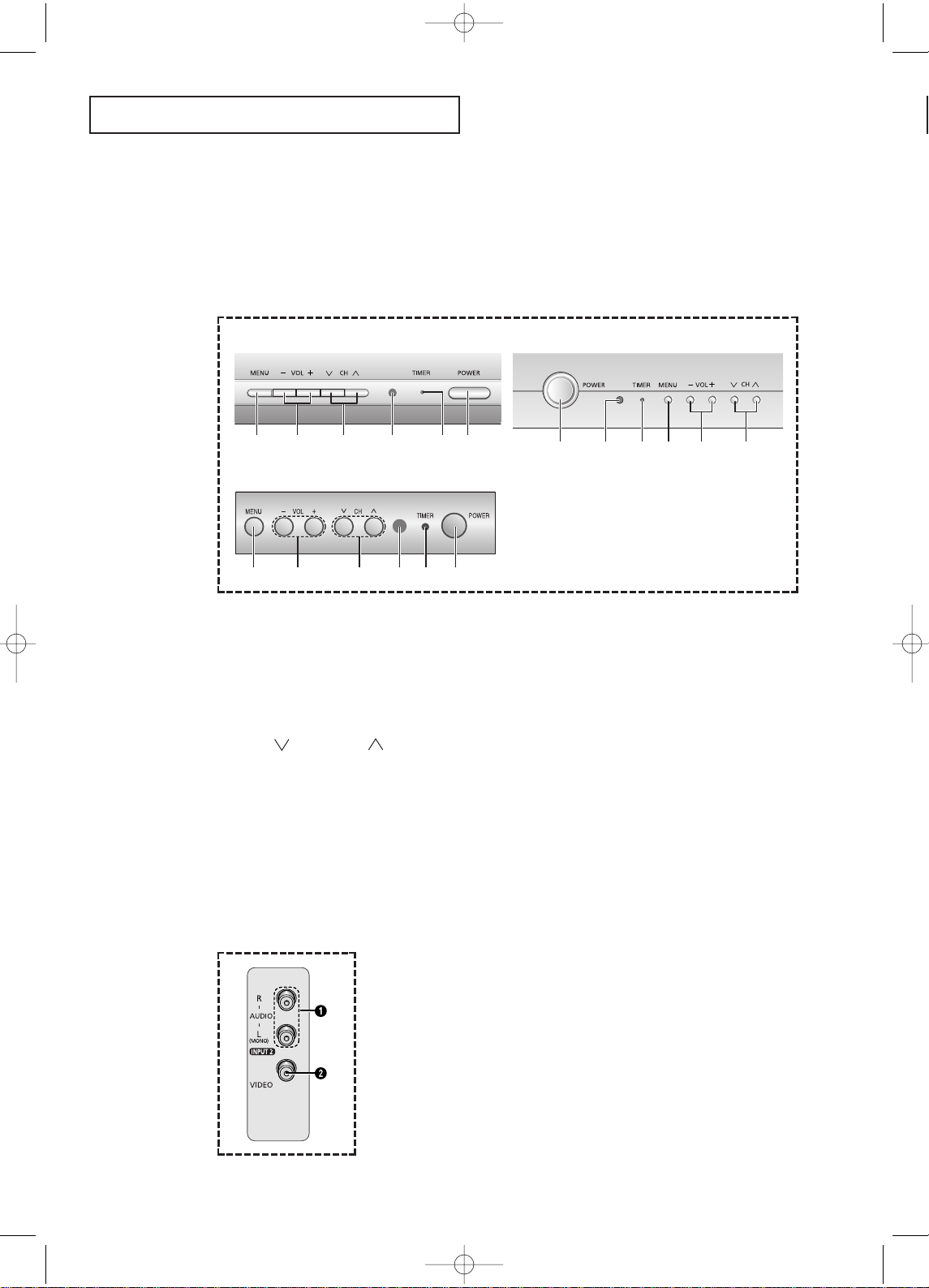
Side Panel Jacks
You can use the side panel jacks to connect an A/V component that is used only occasionally, such as a camcorder or video game. (For information on connecting equipment,
see page 16.)
Œ
AUDIO INPUT
jacks
Used to connect t he audio
signals from a camcorder or
video game.
´
VIDEO INPUT jack
Used to connect a video signal
from a camcorder or video
game.
Familiarizing Yourself with The TV
Front Panel Buttons
The buttons on the front panel control your TV’s basic features, including the on-screen
menu. To use the more advanced features, you must use the remote control.
Œ
MENU
Press to see an on-screen menu of your TV's features.
´
VOL – and +
Press to increase or decrease the
volume. Also used to select items on the onscreen menu.
ˇ
CH and CH
Press to change channels. Also press to select
various items on the on-screen menu.
¨
Remote Control Sensor
Aim the remote control towards this spot on the
TV.
ˆ
TIMER indicator
When the TV is turned on, the TIMER indicator
blinks five times. This indicator illuminates when
the TIMER mode is set to the “On”position after
setting the clock and either the On timer or Off
timer, with the remote control. Even if the power is
turned off, this indicator stays lit. (Clock must be
set before using this function.)
Ø
POWER
Press to turn the TV on and off.
CT29M16MQU CT25M20MQU/CT29M20MQU
CT21T20MQU
Œ ´ ˇ ¨ ˆ Ø
Ø ¨ ˆ Œ ´ ˇ
Œ ´ ˇ ¨ ˆ Ø
AA68-03465A-00Eng_XTC 5/7/04 1:30 PM Page 6
Page 7
YOUR NEW TV
7
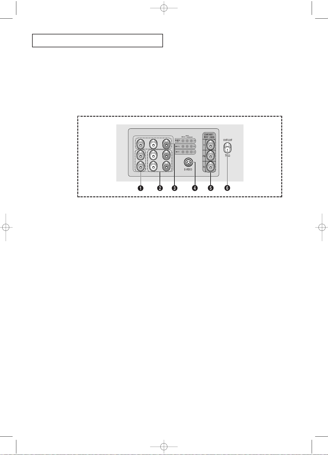
Rear Panel Jacks
Use the rear panel jacks to connect an A/V component that will be connected
continuously, such as a VCR or a DVD player.
Because there are two sets of input jacks, you can connect two different A/V
components (i.e., a VCR and a DVD, 2 VCRs, etc.)
For more information on connecting equipment, see pages 9 – 15.
Œ
VIDEO INPUT jack
Video signals from VCRs, DVD players and similar
devices.
´
AUDIO INPUTS (INPUT1
and 2)
/DVD AUDIO INPUTS
(INPUT 2)
Audio signals from VCRs, DVD players and similar
devices.
Use these jacks to connect the audio signals from a
DVD player when using the DVD video input jacks.
When not using the DVD jacks, these audio jacks
function as audio for Video 2 or S-VIDEO.
ˇ
AUDIO-VIDEO MONITOR
OUTPUT jacks
These audio-video signals are identical to A/V
signals being displayed on the big screen. (Typically
used as the input signals for a recording VCR.)
¨
SUPER VIDEO INPUT jack
(CT29M16MQU/CT25M20MQU/
CT29M20MQU)
S-Video signal from an S-VHS VCR or DVD player.
Note: In S-Video mode, Audio Output depends what
kind of audio input source is connected to the side
audio input jacks (AV2).
ˆ
COMPONENT VIDEO INPUT
jacks
Connect video from a DVD player.
Note: Only black and white signals are output from
a monitor in DVD mode.
Ø
VHF/UHF
Connect to an antenna or to a cable TV system.
AA68-03465A-00Eng_XTC 5/7/04 1:30 PM Page 7
Page 8
YOUR NEW TV
8
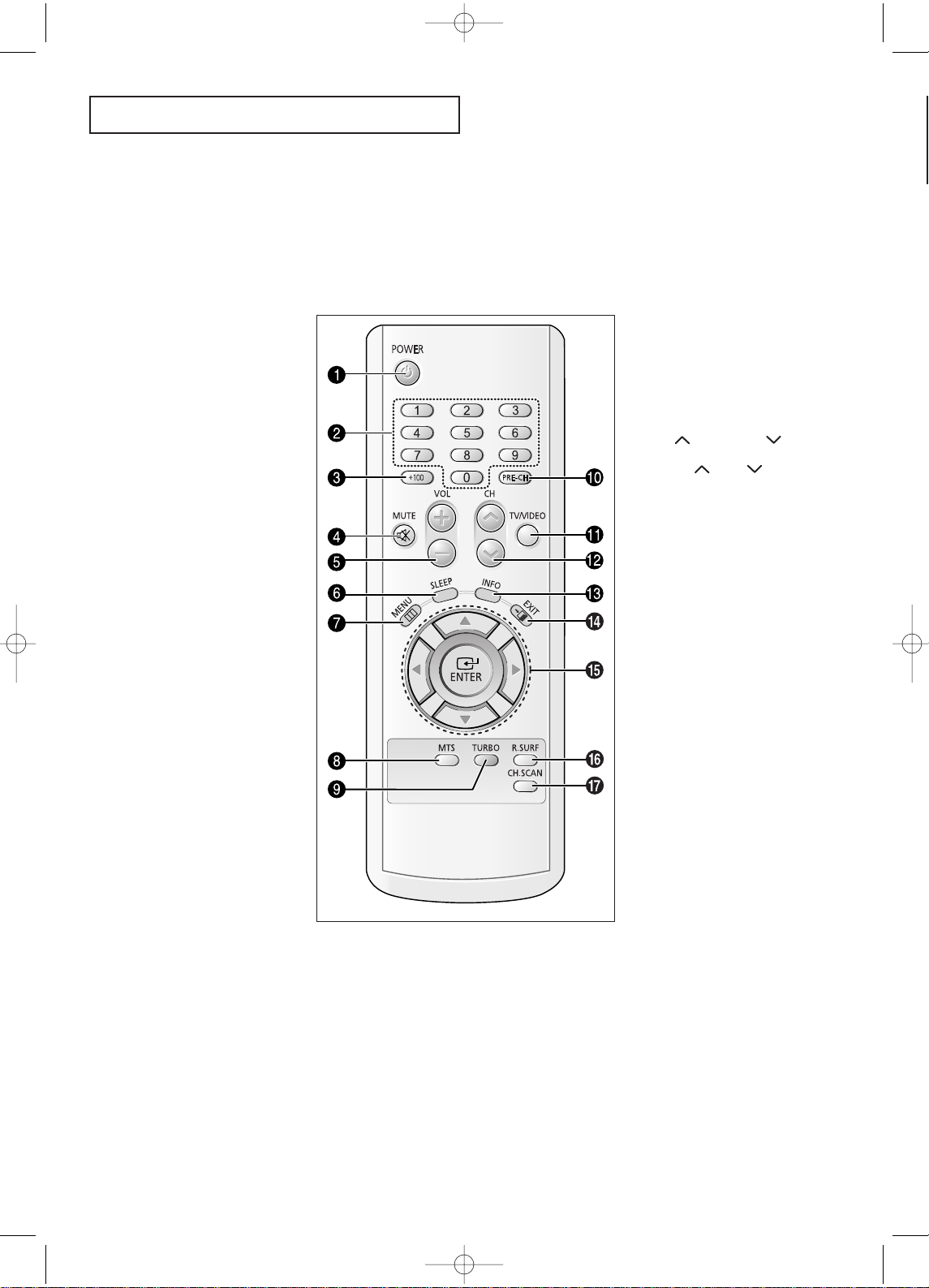
Remote Control
You can use the remote control up to about 23 feet from the TV. When using the remote,
always point it directly at the TV.
Œ
POWER
Turns the TV on and off.
´
Number buttons
Press to select channels directly on
the TV.
ˇ
+100
Press to select channels over 100.
For example, to select
channel 121, press “+100,” then
press “2” and “1.”
¨
MUTE
Press to temporarily cut off
the sound.
ˆ
VOL -, VOL +
Press to increase or decrease the
volume.
Ø
SLEEP
Press to select a preset t ime interval for automatic shutoff.
∏
MENU
Displays the main on-screen menu.
”
MTS (Multichannel
Television Stereo)
Press to choose stereo, mono or
Separate Audio Program (SAP
broadcast).
’
TURBO
Press to turn the TURBO sound On
or Off.
˝
PRE-CH
Tunes to the previous channel.
Ô
TV/VIDEO
Press to display all of the available
video sources (i.e., Antenna/Cable,
VCR).
CH and CH
(Channel Up/Down)
Press CH or CH to change
channels.
Ò
INFO
Press to see the time, channel, etc.,
on- screen.
Ú
EXIT
Press to exi t the menu.
Æ
Up, Down, Left,
Right (▲, ▼, œ, √)/
ENTER
Press to select highlight up, down,
left, or right. While using the onscreen menus, press the ENTER button to activate (or change) a particular item.
ı
R-SURF
Press the SURF button to automatically return to a preferred channel
after a user-preset time delay.
˜
CH.SCAN
Not available.
AA68-03465A-00Eng_XTC 5/7/04 1:30 PM Page 8
Page 9

INSTALLATION
9
Chapter Two
INSTALLATION
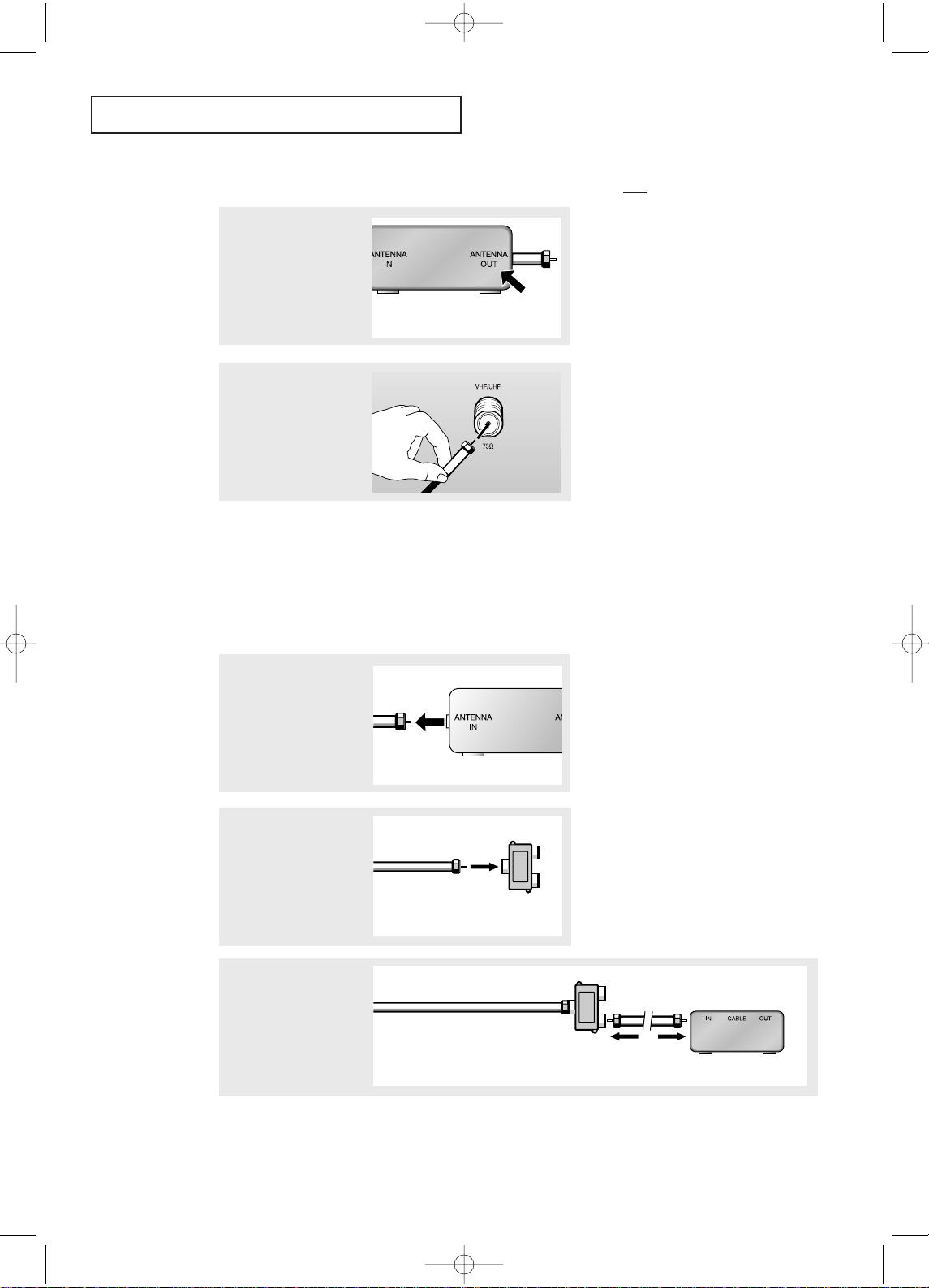
Connecting VHF and UHF Antennas
If your antenna has a set of leads that
look like this, see “Antennas with
300-ohm Flat Twin Leads” below.
If your antenna has one lead that looks
like this, see “Antennas with 75-ohm
Round Leads”, on page next.
If you have two antennas, see “Separate
VHF and UHF Antennas”, on page next.
Antennas with 300-ohm Flat Twin Leads
If you are using an off-air antenna (such as a roof antenna or “rabbit ears”) that has
300-ohm twin flat leads, follow the directions below.
1
Place the wires from
the twin leads under
the screws on the 30075 ohm adaptor (not
supplied). Use a screwdriver to tighten the
screws.
2
Plug the adaptor into
the VHF/UHF terminal
on the bottom of the
back panel.
AA68-03465A-00Eng_XTC 5/7/04 1:30 PM Page 9
Page 10

INSTALLATION
10
Connecting Cable TV
To connect to a cable TV system, follow the instructions below.
Cable without a Cable Box
▼
1
Plug the incoming cable
into the VHF/UHF
antenna terminal on back
of the TV.
Because this TV is
cable-ready, you do not need a
cable box to view unscrambled cable
channels.
2
Plug the combiner into
the VHF/UHF terminal
on the bottom of the
rear panel.
Separate VHF and UHF Antennas
If you have two separate antennas for your TV (one VHF and one UHF), you must
combine the two antenna signals before connecting the antennas to the TV. This
procedure requires a an optional combiner-adaptor (available at most electronics shops).
1
Connect both antenna
leads to t he combiner.
Antennas with 75-ohm Round Leads
1
Plug the antenna lead
into the VHF/UHF
terminal on the bottom of
the back panel.
AA68-03465A-00Eng_XTC 5/7/04 1:30 PM Page 10
Page 11
INSTALLATION
11
Connecting to a Cable Box that Descrambles All Channels
▼
1
Find the cable that is
connected to the ANTENNA OUT terminal on your
cable box.
This terminal might be labeled
“ANT OUT”, “VHF OUT” or simply,
“OUT”.
2
Connect the other end of
this cable to the
VHF/UHF antenna
terminal on the back of
the TV.
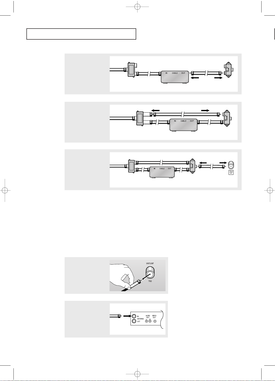
Connecting to a Cable Box that Descrambles Some Channels
If your cable box descrambles only some channels (such as premium channels), follow the
instructions below. You will need a two-way splitter, an RF (A/B) switch and four lengths of
coaxial cable. (These items are available at most electronics stores.)
▼
1
Find and disconnect the
cable t hat is connected
to the ANTENNAIN
terminal on your
cable box.
This terminal might be labeled
“ANT IN”, “VHF IN” or simply,
“IN”.
2
Connect this cable to a
two-way split ter.
3
Connect a coaxial cable
between an OUTPUT terminal on the splitter and
the IN terminal on the
cable box.
Incoming Cable
Split ter
Incoming Cable
Cable Box
Split ter
AA68-03465A-00Eng_XTC 5/7/04 1:30 PM Page 11
Page 12
INSTALLATION
12
Connecting a VCR
These instructions assume that you have already connected your TV to an antenna or a cable
TV system (according to the instructions on pages 9-11). Skip step 1 if you have not yet
connected to an antenna or a cable system.
1
Unplug the cable or
antenna from the back of
the TV.
4
Connect a coaxial cable
between the ANTENNA
OUT terminal on the cable
box and the B–IN terminal
on the RF(A/B) switch.
5
Connect another cable
between the other OUT terminal on the splitter and
the A–IN terminal on the
RF (A/B) switch.
6
Connect the last coaxial
cable bet ween the OUT
terminal on the RF (A/B)
switch and the VHF/UHF
terminal on the rear of the
TV.
After you’ve made this connection, set the A/B switch to the “A” position for normal viewing. Set the A/B switch to the “B” position to view scrambled channels. (When you set the
A/B switch to “B”, you will need to tune your TV to the cable box’s output channel, which is
usually channel 3 or 4.)
Incoming
Cable
Cable Box
RF (A/B)
Switch
Split ter
Incoming
Cable
Cable Box
RF (A/B)
Switch
Split ter
Incoming
Cable
Cable Box
RF (A/B)
Switch
TV R ear
Split ter
2
Connect the cable or
antenna to the
ANTENNA IN terminal on
the back of the VCR.
Incoming
Cable or
Antenna
VCR R ear Panel
AA68-03465A-00Eng_XTC 5/7/04 1:30 PM Page 12
Page 13
INSTALLATION
13
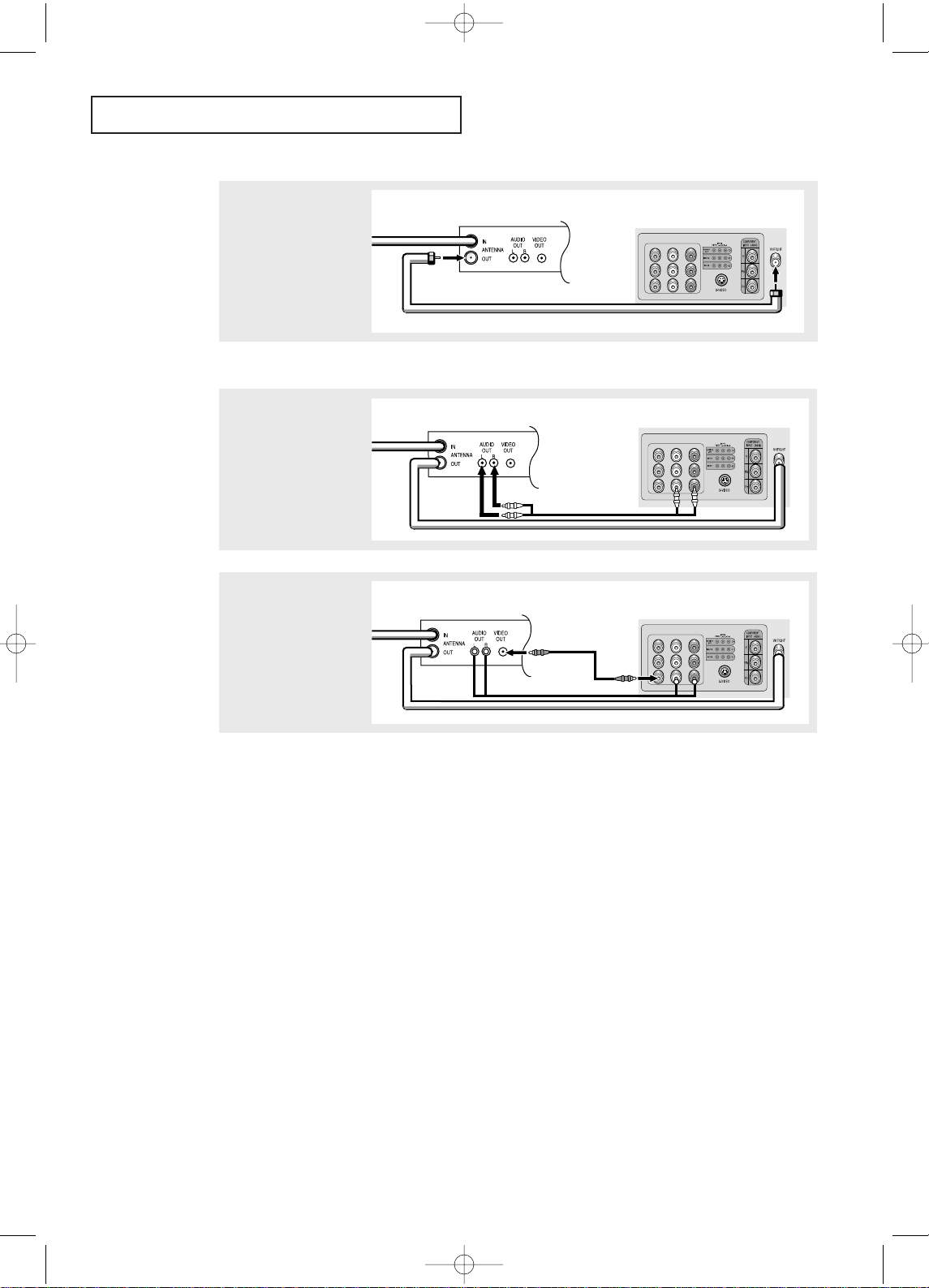
Follow the instructions in “Viewing an External Signal Source” to view your VCR tape.
Note: This figure shows the Standard connector-jack panel. The actual configuration for
your TV may be different.
3
Connect a coaxial cable
between the ANTENNA
OUT terminal on the VCR
and the antenna
terminal on the TV.
4
Connect a set of audio
cables bet ween the
AUDIO OUT jacks on the
VCR and the AUDIO jacks
on the TV.
5
Connect a video cable
between the VIDEO OUT
jack on the VCR and the
VIDEO jack on the TV.
A coaxial cable is usually included with a VCR. (If not, check your local electronics store).
VCR R ear Panel
Coaxial Cable
TV Rear Panel
VCR R ear Panel
Audio Cable
TV Rear Panel
VCR R ear Panel
Video Cable
TV Rear Panel
AA68-03465A-00Eng_XTC 5/7/04 1:30 PM Page 13
Page 14
INSTALLATION
14
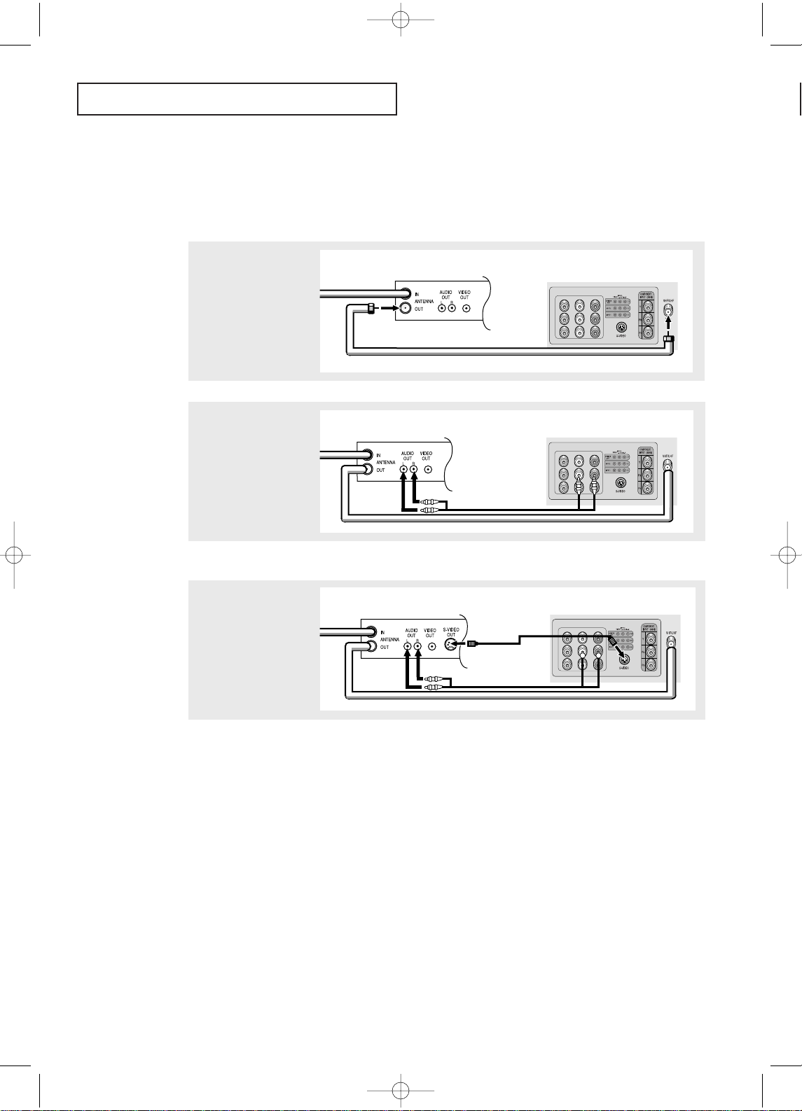
3
Connect an S-video
cable bet ween the
S-VIDEO OUT jack on the
VCR and the
S-VIDEO INPUT
jack on the TV.
An S-video cable is usually included with an S-VHS VCR. (If not, check your local
electronics store.)
Note: This figure shows the Standard connector-jack panel. The actual configuration for
your TV may be different.
Make sure the jacks you are using are underneath the number “2.”
2
Connect a set of audio
cables bet ween the
AUDIO OUT jacks on t he
VCR and the 2 AUDIO
INPUT jacks on the TV.
1
To begin, follow steps
1–3 in the previous
section to connect the
antenna or cable to your
VCR and your TV.
Connecting an S-VHS VCR
(CT29M16MQU/CT25M20MQU/CT29M20MQU)
Your Samsung TV can be connected to an S-Video signal from an S-VHS VCR. (This
connection delivers a better picture as compared to a standard VHS VCR.)
VCR R ear Panel
Coaxial Cable
TV Rear Panel
VCR R ear Panel
Audio Cable
TV Rear Panel
VCR R ear Panel
Video Cable
TV Rear Panel
AA68-03465A-00Eng_XTC 5/7/04 1:30 PM Page 14
Page 15

INSTALLATION
15
Connecting a Second VCR to Record from the TV
Your TV can send out signals of its picture and sound to be recorded by a second VCR.
To do this, connect your second VCR as follows:
1
Connect a set of audio
cables bet ween the
AUDIO OUT jacks on the
TV and the AUDIO IN
jacks on the VCR.
2
Connect a video cable
between the VIDEO OUT
jack on the TV and the
VIDEO IN jack on the
VCR.
Refer to your VCR’s instructions for more information about how to record using this kind
of connection.
(The VCR input jacks might be either on the front or on back of the VCR.)
Connecting a DVD Player
The rear panel jacks on your TV make it easy to connect a DVD player to your TV.
1
Connect a set of audio
cables bet ween the
AUDIO INPUT 2 jacks on
the TV and the AUDIO
OUT jacks on the DVD
player.
2
Connect a video cable
between t he COMPONENTINPUT(Y,Pb,Pr)
jacks on the TV and the
COMPONENT VIDEO OUT
(Y, Pb, Pr) jacks on the
DVD player.
VCR Input Panel
Audio Cable
TV Rear Panel
VCR Input Panel
Video Cable
TV Rear Panel
DVD Player Rear Panel
TV Rear Panel
Audio Cable
DVD Player Rear Panel
TV Rear Panel
Video Cable
Note: For an explanation of Component video, see your DVD player's owner's manual.
Note: This figure shows the Standard connector-jack panel. The actual configuration for
your TV may be different.
AA68-03465A-00Eng_XTC 5/7/04 1:30 PM Page 15
Page 16
INSTALLATION
16
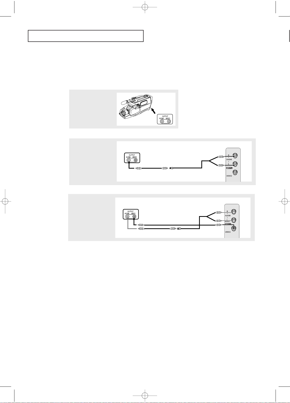
2
Connect an audio cable
between t he AUDIO
OUTPUT jack on the
camcorder and the
AUDIO terminals on the
side of the TV.
3
Connect a video cable
between the VIDEO OUTPUT jack on the camcorder and the VIDEO terminal on the side of the
TV.
1
Locate the A/Voutput
jacks on the camcorder.
They are usually found on
the side or back of the
camcorder.
Connecting a Camcorder
The side panel jacks on your TV make it easy to connect a camcorder to your TV. They allow
you to view the camcorder tapes without using a VCR. (Also see “Viewing an External Signal
Source” on page 35).
The audio-video cables shown here are usually included with a Camcorder. (If not, check
your local electronics store.) If your camcorder is stereo, you need to connect a set of two
cables.
Camcorder
Outpu t Jacks
Camcorder
Outpu t Jacks
Audio Cable
Video Cable
Y- C o n n e c t o r
TV Side Panel
Camcorder
Outpu t Jacks
TV Side Panel
AA68-03465A-00Eng_XTC 5/7/04 1:30 PM Page 16
Page 17

INSTALLATION
17
▼
3
Replace the cover.
Remove the batteries and store
them in a cool, dry place if you won’t
be using the remote control for a
long time.
The remote control can be used up
to about 23 feet from the TV.
(Assuming typical TV usage, the
batteries last for about one year.)
▼
2
Install two AAA size
batteries.
Make sure to match the “+” and
“
–” ends of the batteries with the
diagram inside the compartment.
Installing Batteries in the Remote Control
1
Slide the cover out completely.
AA68-03465A-00Eng_XTC 5/7/04 1:30 PM Page 17
Page 18

OPERATION
18
OPERATION
Chapter Three
OPERATION
1
Press the POWER button
on the remote control.
The message “Plug &
Play” is displayed.
It flickers for a little while
and then the “Language”
menu is automatically displayed.
Turning the TV On and Off
Press the POWER but ton on the remote control.
You can also use the POWER button on the front panel.
Plug & Play Feature
When the TV is initially powered On, five basic customer settings proceed automatically
and subsequently: Setting the language, Video signal source, Ant. input check, Auto
program and Clock.
Plug & Play
3
Press the MENU button
then t he “Ant Input check”
is automatically displayed.
Make sure that the antenna
is connected to the TV.
Press the ENTER button
and then the “Channel”
menu is automatically
displayed.
2
Press the
œœ
or √√button to
select the desired
language.
Adjust Skip
Setup
Time
√√
Plug & Play
√√
Caption
√√
Language : English
▼
More
Ant Input check
Auto Program Exit
4
Press the
œœ
or √√button to
select signal source (Air,
STD, HRC, IRC).
Adjust Skip
Channel
Auto Program
√√
Add/Delete : Deleted
√√
Air/CATV : Air
Name :
----
AA68-03465A-00Eng_XTC 5/7/04 1:31 PM Page 18
Page 19

OPERATION
19
7
Press the ENTER button
and then press the œœor
√√
button to move the hour or
minute. Set the hour or
minute by pressing the ▲ or
▼ button. (refer to “Setting
the Clock” on page 30.)
8
When you have finished,
press the MENU but ton.
The message “Enjoy your
watching..” is displayed.
Note: Plug & Play feature doesn’t work when in the AV mode.
Enjoy your watching..
Move Adjust Return
Time
Clock 12 :00 am
On Timer - - : - - am Off
Off Timer - - : - - am Off
Sleep Timer : Off
On Timer Volume : 10
Move Enter Return
Setup
Time
√√
Plug & Play
√√
Caption
√√
Language : English
▼
More
6
Press the ENTER button to
start “Auto Program” or
press the MENU but ton to
return.(refer to “Auto pro-
gram” on page 25.) The TV
will begin memorizing all of
the available channels.
Auto Program
Air 7
Enter Return
Stop
5
Press the MENU button and
then t he “Auto Program” is
automatically displayed.
Auto Program
Air 3
Enter Return
Start
9
If you want to reset this feature
(1)Press the MENU button.
(2)Press the
▲ or ▼ button
to select the “Setup”, then
press the
ENTER button.
(3)Press the
▲ or ▼ button
to select “Plug & Play”,
then press the ENTER but-
ton.The message “Plug &
Play” is displayed.
AA68-03465A-00Eng_XTC 5/7/04 1:31 PM Page 19
Page 20

OPERATION
20
Viewing the Display
The display identifies the current channel and the status
of certain audio-video settings.
▼
The on-screen displays
disappear after ten seconds.
Viewing the Menus and On-Screen Displays
Viewing the Menus
▼
1
With the power on, press
the MENU button.
The main menu appears on
the screen. Its left side has
five icons: Input, Picture,
Sound, Channel and Setup.
The on-screen menus disappear
from the screen after two minutes.
▼
You can also use the MENU, CH
and VOL buttons on the control
panel of the TV to make selections.
1
Press the INFO button.
The on-screen display
shows any or all of the
following:
Active channel, t he
channel label, signal, picture mode, sound mode,
MTS and the
current time.
2
Use the ▲ and ▼ buttons to highlight one of the 5 icons.
Then press the ENTER button to access the icon’s sub-menu.
3
Press the EXIT button to exit.
Move Enter Exit
Source List : TV
√√
Edit Name
√√
Input
Air 10
Signal : Mono
Sound : Custom
Picture : Custom
MTS : Stereo
12 : 00 am
AA68-03465A-00Eng_XTC 5/7/04 1:31 PM Page 20
Page 21

OPERATION
21
Selecting a Menu Language
1
Press the MENU button to
display the menu.
Press the ▲ or ▼ button
to select “Setup”, then
press the ENTER but ton.
3
Press the
œœ
or
√√
button to
select the appropriate
language: “English”,
“Español” or “Português”.
Press the EXIT button to
exit.
Move Enter Return
Setup
Time
√√
Plug & Play
√√
Caption
√√
Language : English
▼
More
2
Press the ▲ or ▼ button
to select “Language”, t hen
press the ENTER but ton.
Mover Ajuste Regresar
Configuración
Tiempo
√√
Plug & Play
√√
Subtítulos
√√
Idioma : Español
▼
Más
Move Adjust Return
Setup
Time
√√
Plug & Play
√√
Caption
√√
Language : English
▼
More
AA68-03465A-00Eng_XTC 5/7/04 1:31 PM Page 21
Page 22

OPERATION
22
Memorizing the Channels
Your TV can memorize and store all of the available channels for both “off-air” (antenna)
and cable channels. After the available channels are memorized, use the CH and
CH buttons to scan through the channels. This eliminates the need to change channels by entering the channel digits. There are three steps for memorizing channels:
selecting a broadcast source, memorizing the channels (automatic) and adding and deleting channels (manual).
Selecting the Video Signal-source
Before your television can begin memorizing the available channels, you must specify the
type of signal source that is connected to the TV (i.e., an antenna or a cable system).
1
Press the MENU button to
display the menu.
Press the ▲ or ▼ button to
select “Channel”, then press
the ENTER button
2
Press the ▲ or ▼ button
to select “Air/CATV”, then
press the ENTER but ton
Note: STD, HRC and IRC identify various types of cable
TV systems. Contact your local cable company to identify
the type of cable system that exists in your particular area.
At this point the signal source has been selected. Proceed
to “Storing Channels in Memory” (next page).
Move Enter Return
Channel
Auto Program
√√
Add/Delete : Deleted
√√
Air/CATV : Air
Name :
----
Move Adjust Return
Channel
Auto Program
√√
Add/Delete : Deleted
√√
Air/CATV : Air
Name :
----
3
Repeatedly press the
œœ
or √√button to cycle
through these choices:
“Air” (antenna) “STD”,
“HRC” or “IRC” (all cable
TV)
Press the EXIT button to
exit.
Move Adjust Return
Channel
Auto Program
√√
Add/Delete : Deleted
√√
Air/CATV : STD
Name :
----
AA68-03465A-00Eng_XTC 5/7/04 1:31 PM Page 22
Page 23

OPERATION
23
3
Press the ENTER button
to start "Auto Program".
The TV will begin
memorizing all of the available channels.
After all the available channels are stored, the Auto
program menu reappears.
Press the MENU button to
skip and press the ENTER
button to stop.
Storing Channels in Memory (Automatic Method)
▼
The TV automatically cycles
through all of the available channels
and stores them in memory. This
takes about one to two minutes.
2
Press the ▲ or ▼ button
to select “Auto program”
and then press the ENTER
but ton.
The “Auto Program” is
automatically displayed.
1
First , select the correct signal source (Air, STD, HRC,
IRC). See steps 1~3 on previous page.
Move Adjust Return
Channel
Auto Program
√√
Add/Delete : Deleted
√√
Air/CATV : Air
Name :
----
Move Enter Return
Channel
Auto Program
√√
Add/Delete : Deleted
√√
Air/CATV : Air
Name :
----
Auto Program
Air 3
Enter Return
Start
Auto Program
Air 5
Enter Return
Stop
AA68-03465A-00Eng_XTC 5/7/04 1:31 PM Page 23
Page 24

OPERATION
24
Adding and Erasing Channels (Manual Method)
First, press the CH or CH button or the number buttons
to select the channel you want to add or delete.
1
Press the MENU button to
display the menu.
Press the ▲ or ▼ button
to select “Channel”, then
press the ENTER but ton.
2
Press the ▲ or ▼ but ton
to select “Add/Delete”,
then press the ENTER
but ton.
3
Press the ▲ or ▼ but ton
to select “Added” or
“Deleted” then press the
ENTER button.
Press the EXIT button to
exit.
Move Enter Return
Channel
Auto Program
√√
Add/Delete : Deleted
√√
Air/CATV : Air
Name :
----
Move Enter Return
Channel
Auto Program
√√
Add/Delete : Deleted
Air/CATV : Air
Name :
----
Deleted
Added
Move Enter Return
Channel
Auto Program
√√
Add/Delete : Deleted
√√
Air/CATV : Air
Name :
----
AA68-03465A-00Eng_XTC 5/7/04 1:31 PM Page 24
Page 25

OPERATION
25
Changing Channels
Using the Channel Buttons
1
Press the CH or CH button to change channels.
When you press CH or CH , the TV changes channels in sequence. You will see all the
channels that the TV has memorized. (The TV must have memorized at least three channels.)
You will not see channels that were either erased or not memorized.
Directly Accessing Channels
Use the number buttons to quickly tune to any channel.
1
Press the number buttons to go directly to a channel. For example,
to select channel 27, press “2” then “7”. The T V will change channels
when you press the second number.
When you use the number buttons, you can directly select channels that were either erased
or not memorized.
To select a channel over 100, press the
+100 button. (For channel 122, press “+100” then “2”
then “2”.)
To change to single-digit channels (0–9) faster, press “0” before the single digit.
(For channel “4” press “0” then “4”.)
Using the PRE-CH Button to select the Previous Channel
1
Press the PRE-CH button.
The TV will switch to the
last channel viewed.
▼
To quickly switch between two
channels that are far apart, tune to
one channel, then use the number
button to select the second channel.
Then, use the PRE-CH button to
quickly alternate between them.
AA68-03465A-00Eng_XTC 5/7/04 1:31 PM Page 25
Page 26

OPERATION
26
Labeling the Channels
Use this feature to assign an easy-to-remember label to any channel (i.e., “CBS”,
“ESPN”, “PBS2”, CNN1”, etc.) A label consists of four fields, where each field is a letter,
a number, “*”, or a blank. When the INFO button is pressed, the channel label will
appear next to the channel number.
1
Press the CH or CH
button to tune to the
channel that will be labeled.
2
Press the MENU button to
display the menu.
Press the ▲ or ▼ button
to select “Channel”, then
press the ENTER but ton.
3
Press the ▲ or ▼ button to
select “Name”.
Press the
√√
button to begin
labeling. The left-most field
will be highlight.
(Each label has four fields.
See top paragraph.)
4
Press the ▲ or ▼ button
to select a let ter, a number,
“*” or a blank.
(Pressing ▲ or ▼ button
result s in this sequence:
A, B,...Z, *, blank, 0, 1, ...9).
▼
Note: You cannot select “Name”
in the AV mode.
5
Press the
√√
button to
switch to the next field,
which will be highlight.
Select a second let ter or
digit using the ▲ or ▼
button, as above.
Repeat t he process to select
the last two digits.
Press the EXIT button to
exit.
Air 11
Move Enter Return
Channel
Auto Program
√√
Add/Delete : Deleted
√√
Air/CATV : Air
Name :
----
Move Adjust Return
Channel
Move Adjust Return
Channel
Move Enter Return
Channel
Auto Program
√√
Add/Delete : Deleted
√√
Air/CATV : Air
Name :
----
Auto Program
√√
Add/Delete : Deleted
√√
Air/CATV : Air
Name :
P
---
Auto Program
√√
Add/Delete : Deleted
√√
Air/CATV : Air
Name :
PBS2
AA68-03465A-00Eng_XTC 5/7/04 1:31 PM Page 26
Page 27

OPERATION
27
Adjusting the Volume
Press the VOL + or – VOL – but ton to increase or decrease the volume.
Using the MUTE Button
At any time, you can temporarily cut off the sound using the MUTE button.
1
Press the MUTE button and
the sound cuts off.
The word “Mute” will appear
in the lower-left corner of
the screen.
2
To turn mute off, press the MUTE button to again, or simply press
either the VOL + or VOL – but ton.
Mute
AA68-03465A-00Eng_XTC 5/7/04 1:31 PM Page 27
Page 28

OPERATION
28
Setting the Clock
1
Press the MENU button to
display the menu.
Press the ▲ or ▼ button
to select “Setup”, then
press the ENTER but ton.
▼▼
When selecting the hours, be sure
to select the proper time of day (am or
pm).
You can change the hours by pressing
the
▲ or ▼ button repeatedly (or by
holding down either of these buttons).
3
After the hour is entered,
Press the √√but ton.
(at this point the minutes
digits will be highlighted).
Press the ▲ or ▼ button
to select the correct minutes.
After selecting the correct minutes,
press the √√but ton.
Press the EXIT button to exit.
The time will appear every time
you press the INFO button.
Move Enter Return
Setup
Time
√√
Plug & Play
√√
Caption
√√
Language : English
▼
More
Move Adjust Return
Time
Clock 09: - - am
On Timer - - : - - am Off
Off Timer - - : - - am Off
Sleep Timer : Off
On Timer Volume : 10
Move Adjust Return
Time
Clock 09: 30am
On Timer - - : - - am Off
Off Timer - - : - - am Off
Sleep Timer : Off
On Timer Volume : 10
2
Press the ENTER button.
Press the ENTER button
again to select the hours.
(the hours digits will be
highlighted).
Press the ▲ or ▼ button
repeatedly un til the
correct hour appears.
AA68-03465A-00Eng_XTC 5/7/04 1:31 PM Page 28
Page 29

OPERATION
29
1
Press the MENU button to
display the menu.
Press the ▲ or ▼ button
to select “Picture”, then
press the ENTER but ton.
Customizing the Picture
You can use the on-screen menus to change the Contrast, Brightness, Sharpness, Color,
Tint and according to personal preference. (Alternatively, you can use one of the
“Automatic” settings. See next page.)
4
Press the œœor√√button to
increase or decrease the
value of a particular item.
For example, if you select
“Brightness”,pressing
the √√button increases it.
Press the EXIT button to
exit.
▼
After adjusting an item, the gauge
will automatically disappear (after
about 10 seconds).
2
Press the ▲ or ▼ button
to select “Custom”, then
press the ENTER but ton.
(The words Contrast,
Bright ness, Sharpness,
Color and Tint will appear
on the screen.)
3
Press the ▲ or ▼ but ton
to select a particular item,
then press the ENTER
but ton.
Move Enter Return
Mode : Custom
√√
Custom
√√
Color tone : Normal
√√
Size : Normal
√√
▼
More
Picture
Move Enter Return
Contrast : 80
Brightness : 50
Sharpness : 50
Color : 50
Tint : G50 R50
Custom
Move Enter Return
Mode : Custom
√√
Custom
√√
Color tone : Normal
√√
Size : Normal
√√
▼
More
Picture
Brightness 55
Move Adjust Return
AA68-03465A-00Eng_XTC 5/7/04 1:31 PM Page 29
Page 30

OPERATION
30
Using Automatic Picture Settings
Your TV has three automatic picture settings (“Dynamic”, “Standard” and “Movie” ) that
are preset at the factory. You can activate either Dynamic, Standard, Movie or Custom
by pressing the P.MODE button (or by making a selection from the menu). Or, you can
select “Custom” which automatically recalls your personalized picture settings.
• Choose Dynamic for viewing the TV during the day or when there is
bright light in the room.
• Choose
Standardfor the standard factory settings.
• Choose
Movie when viewing the movie.
• Choose
Custom if you want to adjust the settings according to personal
preference (see “Customizing the Picture”, page 29).
1
Press the MENU button to
display the menu.
Press the ▲ or ▼ but ton
to select “Picture”, then
press the ENTER but ton.
2
Press the ENTER button
again.
Press the ▲ or ▼ but ton
to select the “Dynam ic”,
“Standard”“Movie” or
“Custom” picture setting,
then press the ENTER
but ton.
Press the EXIT button to
exit.
Move Enter Return
Mode : Custom
√√
Custom
√√
Color tone : Normal
√√
Size : Normal
√√
▼
More
Picture
Move Enter Return
Mode : Custom
Custom
Color tone : Normal
Size : Normal
▼
More
Picture
Dynamic
Standard
Movie
Custom
AA68-03465A-00Eng_XTC 5/7/04 1:31 PM Page 30
Page 31

OPERATION
31
2
Press the ▲ or ▼ button
to select “Custom”, then
press the ENTER but ton.
1
Press the MENU button to
display the menu.
Press the ▲ or ▼ button
to select the “Sound”, then
press the ENTER but ton.
Customizing the Sound
You can use the on-screen menus to adjust the bass, treble and balance according
to individual preference. (Alternatively, you can use one of the “automatic” settings.
See next page.)
3
Press the ▲ or ▼ but ton
to select a particular item,
then press the ENTER but-
ton.
Move Enter Return
Sound
Mode : Custom
√√
Custom
√√
MTS : Stereo
√√
Auto Volume : Off
√√
▼
More
Move Enter Return
Sound
Mode : Custom
√√
Custom
√√
MTS : Stereo
√√
Auto Volume : Off
√√
▼
More
Move Enter Return
Custom
Bass : 50
Treble : 50
Balance : L 50 R 50
4
Press the œœor√√button to
increase or decrease the
value of a particular item.
For
example, if you select
“Tr e b l e ”, pressing the
√√
button increases it.
Press the
EXIT button to
exit.
Treble 55
Move Adjust Return
AA68-03465A-00Eng_XTC 5/7/04 1:31 PM Page 31
Page 32

OPERATION
32
Using Automatic Sound Settings
Your TV has four automatic sound settings (“Standard”, “Music”, “Movie” and “Speech”)
that are preset at the factory. You can activate either Standard, Music, Movie or Speech
by pressing the S.MODE button (or by making a selection from the menu). Or, you can
select “Custom”, which automatically recalls your personalized sound settings.
• Choose Standardfor the standard factory settings.
• Choose
Music when watching music videos or concerts.
• Choose
Movies when watching movies.
• Choose
Speech when watching a show that is mostly dialogue (i.e., news).
• Choose
Custom to recall your personalized settings.
(see “Customizing the Sound”, page 31).
2
Press the ENTER button
again.
Press the ▲ or ▼ but ton
repeatedly to select the
“Standard”, “Music”
“Movie”, “Speech” or
“Custom” sound settings,
then press the ENTER
but ton.
Press the EXIT button to
exit.
1
Press the MENU button to
display the menu.
Press the ▲ or ▼ button
to select the “Sound”, then
press the ENTER but ton.
Move Enter Return
Sound
Mode : Custom
√√
Custom
√√
MTS : Stereo
√√
Auto Volume : Off
√√
▼
More
Move Enter Return
Sound
Mode : Custom
Custom
MTS : Mono
Auto Volume : Off
▼
More
Standard
Music
Movie
Speech
Custom
AA68-03465A-00Eng_XTC 5/7/04 1:31 PM Page 32
Page 33

OPERATION
33
1
Press the MENU button to
display the menu.
Press the ▲ or ▼ button
to select the “Setup”, then
press the ENTER but ton.
2
Press the ▲ or ▼ but ton
to select "Blue Screen",
then press the ENTER
but ton.
3
Press the ▲ or ▼ button
to select Blue Screen “On”,
then press the ENTER but-
ton.
Press the EXIT button to
exit.
▼
Pressing the ▲ or ▼ button will
alternate between “On” and “Off”.
Setting the Blue Screen Mode
If no signal is being received or the signal is very weak, a blue screen automatically
replaces the noisy picture background. If you wish to continue viewing the poor picture,
you must set the “Blue screen” mode to “Off”.
Move Enter Return
Setup
▲
More
Blue Screen : On
√√
Melody : On
√√
Demonstration
√√
Move Enter Return
Setup
▲
More
Blue Screen : On
Melody : On
√√
Demonstration
√√
Off
On
Move Enter Return
Setup
Time
√√
Plug & Play
√√
Caption
√√
Language : English
▼
More
AA68-03465A-00Eng_XTC 5/7/04 1:31 PM Page 33
Page 34

OPERATION
34
1
Press the MENU button to
display the menu.
Press the ▲ or ▼ button
to select the “Setup”, then
press the ENTER but ton.
2
Press the ▲ or ▼ button
to select “Melody ”, t hen
press the ENTER but ton.
Setting The On/Off Melody
You can hear clear a melody sound when the TV is powered on or Off.
Move Enter Return
Setup
▲
More
Blue Screen : On
√√
Melody : On
√√
Demonstration
√√
3
Press the ▲ or ▼ but ton
to select “On”, then press
the ENTER button.
Press the EXIT button to
exit.
Move Enter Return
Setup
▲
More
Blue Screen : On
√√
Melody : On
Demonstration
√√
Off
On
Move Enter Return
Setup
Time
√√
Plug & Play
√√
Caption
√√
Language : English
▼
More
AA68-03465A-00Eng_XTC 5/7/04 1:31 PM Page 34
Page 35

OPERATION
35
▼
Quick way to access the external
signal source: Just press the
“TV/VIDEO” button on the remote
control.
Viewing an External Signal Source
Use the remote control to switch between viewing signals from connected equipment,
such as VCRs, DVD, Set-Top Box and the TV source (broadcast or cable).
Setting the Signal Source
1
Press the MENU button to
display menu, then press the
ENTER button.
2
Press the ENTER button
again.
Press the ▲ or ▼ button
to select signal source,
then press the ENTER
but ton.
Press the EXIT button to
exit.
Move Enter Return
Source List : TV
√√
Edit Name
√√
Input
Move Enter Return
TV
AV1
----
AV2
----
S-Video
----
Component
----
Source List
AV 1
AA68-03465A-00Eng_XTC 5/7/04 1:31 PM Page 35
Page 36

OPERATION
36
Assigning Names to External input mode
1
Press the MENU button to
display menu, then press the
ENTER button.
2
Press the ▲ or ▼ but ton
to select the “Edit Name”,
then press the ENTER
but ton.
Move Enter Return
Source List : TV
√√
Edit Name
√√
Input
Move Enter Return
Source List : AV1
√√
Edit Name
√√
Input
3
Press the ▲ or ▼ but ton
to select the Source List,
then press the ENTER
but ton.
Move Enter Return
AV1
:
----
√√
AV2
:
----
√√
S-Video
:
----
√√
Component
:
----
√√
Edit Name
4
Press the ▲ or ▼ button
to select external device
( VCR,DVD,Cable STB,
Sat. STB, AV Recv, DVD
Recv, Game, Camcorder,
DVD Combo), then press
the ENTER button.
Set other signal sources
(AV2, S-Video, Component)
using the same method as
listed above.
Press the EXIT button to
exit.
Move Enter Return
AV1
:
----
√√
AV2
:
----
√√
S-Video
:
----
√√
Component
:
----
√√
Edit Name
----
VCR
DVD
Cable STB
Sat. STB
AV Recv
DVD Recv
Game
Camcorder
DVD Combo
AV 1 VCR
AA68-03465A-00Eng_XTC 5/7/04 1:31 PM Page 36
Page 37

SPECIAL FEATURES
37
Changing the Color Tone
1
Press the MENU button to
display the menu.
Press the ▲ or ▼ but ton
to select the “Picture”, then
press the ENTER but ton.
2
Press the ▲ or ▼ but ton
to select “Color tone”, then
press the ENTER but ton.
3
Press the ▲ or ▼ button
to select “Cool2”, “Cool1”,
”Normal”, “Warm1” or
“Warm2” according to per-
sonal preference, then
press the
ENTER button.
Press the
EXIT button to
exit.
Move Enter Return
Mode : Custom
√√
Custom
√√
Color tone : Normal
√√
Size : Normal
√√
▼
More
Picture
Move Enter Return
Mode : Custom
√√
Custom
√√
Color tone : Normal
Size : Normal
√√
▼
More
Picture
Cool2
Cool1
Normal
Warm1
Warm2
Move Enter Return
Mode : Custom
√√
Custom
√√
Color tone : Normal
√√
Size : Normal
√√
▼
More
Picture
SPECIAL FEATURES
Chapter Four
SPECIAL FEATURES
AA68-03465A-00Eng_XTC 5/7/04 1:31 PM Page 37
Page 38

SPECIAL FEATURES
38
• Normal (4:3) : Sets the picture to 4:3 normal mode.
• Zoom : Magnifies the size of the picture on screen.
Changing the Screen Size
1
Press the MENU button to
display the menu.
Press the ▲ or ▼ but ton
to select the “Picture”, then
press the ENTER but ton.
2
Press the ▲ or ▼ but ton
to select “Size”, then press
the ENTER button.
3
Press the ▲ or ▼ button
to select “Normal” or
“Zoom”, then press the
ENTER button.
Press the EXIT button to
exit.
Move Enter Return
Mode : Custom
√√
Custom
√√
Color tone : Normal
√√
Size : Normal
√√
▼
More
Picture
Move Enter Return
Mode : Custom
√√
Custom
√√
Color tone : Normal
√√
Size : Normal
▼
More
Picture
Normal
Zoom
Move Enter Return
Mode : Custom
√√
Custom
√√
Color tone : Normal
√√
Size : Normal
√√
▼
More
Picture
Normal Zoom
AA68-03465A-00Eng_XTC 5/7/04 1:31 PM Page 38
Page 39

SPECIAL FEATURES
39
Digital Noise Reduction
If the broadcast signal received by your TV is weak, you can activate the Digital Noise
Reduction feature to help reduce any static and ghosting that may appear on the screen.
1
Press the MENU button to
display the menu.
Press the ▲ or ▼ but ton
to select the “Picture”, then
press the ENTER but ton.
2
Press the ▲ or ▼ but ton
to select “Digital NR”, t hen
press the ENTER but ton.
3
Press the ▲ or ▼ button
to select “On”, then press
the ENTER button.
Press the EXIT button to
exit.
▼
Pressing the ▲ or ▼ button will
alternate between “On” and “Off”.
Move Enter Return
▲
More
Digital NR : Off
√√
Picture
Move Enter Return
▲
More
Digital NR : Off
Picture
Off
On
Move Enter Return
Mode : Custom
√√
Custom
√√
Color tone : Normal
√√
Size : Normal
√√
▼
More
Picture
AA68-03465A-00Eng_XTC 5/7/04 1:31 PM Page 39
Page 40

SPECIAL FEATURES
40
DNIe Jr
TM
(Digital Natural Image engine)
(CT25M20MQU/CT29M20MQU/CT21T20MQU)
Samsung’s New Technology enables an improved image with detail, contrast and white
enhancement and 3D noise reduction.
1
Press the MENU button to
display the menu.
Press the ▲ or ▼ but ton
to select the “Picture”, then
press the ENTER but ton.
2
Press the ▲ or ▼ but ton
to select "DNIe Jr”, then
press the ENTER but ton.
3
Press the œœor √√button to
select “On”, then press the
ENTER button.
Press the EXIT button to
exit.
Move Enter Return
▲
More
Digital NR : Off
√√
DNIe Jr : On
√√
Picture
Move Enter Return
Mode : Custom
√√
Custom
√√
Color tone : Normal
√√
Size : Normal
√√
▼
More
Picture
Adjust Enter Return
DNIe Jr
Off On
AA68-03465A-00Eng_XTC 5/7/04 1:31 PM Page 40
Page 41

SPECIAL FEATURES
41
Tilt
(CT29M16MQU/CT29M20MQU)
Due to the Earth’s magnetic field there may be same minor image tilt depending
on the TV’s location. When this occurs, follow the steps below.
1
Press the MENU button to
display the menu.
Press the ▲ or ▼ but ton
to select the “Picture”, then
press the ENTER but ton.
2
Press the ▲ or ▼ but ton
to select “Tilt”.
3
Press the œœor √√button to
adjust the Tilt.
Press the EXIT button to
exit.
Move Adjust Return
▲
More
Digital NR : Off
√√
Tilt :
0
Picture
Move Adjust Return
Picture
Move Enter Return
Mode : Custom
√√
Custom
√√
Color tone : Normal
√√
Size : Normal
√√
▼
More
Picture
▲
More
Digital NR : Off
√√
Tilt :
2
AA68-03465A-00Eng_XTC 5/7/04 1:31 PM Page 41
Page 42

SPECIAL FEATURES
42
Using the R.Surf Feature
This feature allows you to set the TV to return to a particular channel after a certain
amount of time. For example, you may be watching a channel when commercials start.
You can set the R.Surf to “5 minutes”, then switch channels. After minutes, the TV will
return to the original channel. To use the R.Surf feature:
1
While you are watching the
channel to which you want
to return, press the R.SURF
button. The on-screen display will read “Surf off”.
2
Press the R.SURF button
again to set the timer in
thir ty second intervals, up
to five minutes.
3
The time you set will begin counting down on the screen.
When the time runs out, the TV will return to the channel you
were watching when you set the timer.
Surf Off
Surf 0: 30
AA68-03465A-00Eng_XTC 5/7/04 1:31 PM Page 42
Page 43

SPECIAL FEATURES
43
Choosing a Multi-Channel Sound (MTS) Soundtrack
Depending on the particular program being broadcast, you can listen to Stereo, Mono, or
a Separate Audio Program. (SAP audio is usually a foreign-language translation.
Sometimes SAP has unrelated information like news or weather.)
2
Press the ▲ or ▼ button
to select the “MTS”, then
press the ENTER but ton.
3
Press the ▲ or ▼ button
to select “Mono”, “Stereo”or
“SAP”, then press the
ENTER button.
Press the EXIT button to
exit.
▼
The text at the bottom of the
menu tells you if the incoming
audio is Mono, Stereo or SAP.
1
Press the MENU button to
display the menu.
Press the ▲ or ▼ button
to select the “Sound”, then
press the ENTER but ton.
• Choose Mono for channels that are broadcasting in mono, or if you are
having difficulty receiving a stereo signal.
• Choose Stereo for channels that are broadcasting in stereo.
• Choose SAP to listen to the Separate Audio Program, which is usually a
foreign-language translation.
▼
Quick way to access the MTS:
Just press the “MTS” button on the
remote control.
Move Enter Return
Sound
Mode : Custom
√√
Custom
√√
MTS : Stereo
√√
Auto Volume : Off
√√
▼
More
Move Enter Return
Sound
Mode : Custom
√√
Custom
√√
MTS : Mono
Auto Volume : Off
√√
▼
More
Mono
Stereo
SAP
Move Enter Return
Sound
Mode : Custom
√√
Custom
√√
MTS : Stereo
√√
Auto Volume : Off
√√
▼
More
AA68-03465A-00Eng_XTC 5/7/04 1:31 PM Page 43
Page 44

SPECIAL FEATURES
44
Extra sound settings (Auto Volume, Turbo Sound or Pseudo Stereo)
The following sound settings can be adjusted to suit your personal preferences
• Auto Volume
Each broadcasting station has its own signal conditions, which can make it necessary
to adjust the volume every time the channel is changed. “Auto volume” lets you
automatically adjust the volume of the desired channel by lowering the sound out
put when the modulation signal is high or by raising the sound output when the
modulation signal is low.
• Turbo Sound
Turbo sound emphasizes the bass and treble frequencies to add fullness to the sound.
You can select the turbo sound by simply pressing the “TURBO” button on the remote
control.
• Pseudo Stereo
“Pseudo Stereo” converts a monaural sound signal into two identical left and right
channels. Once the “Pseudo Stereo” is set to “On” or “Off”, the setting applies to the
sound effects such as “Standard”, “Music”, “Movie” and “Speech”.
1
Press the MENU button to
display the menu.
Press the ▲ or ▼ button
to select the “Sound”, then
press the ENTER but ton.
2
Press the ▲ or ▼ button
to select the required item
(Aut o Volume, Turbo Sound,
Pseudo Stereo), then press
the ENTER button.
Move Enter Return
Sound
Mode : Custom
√√
Custom
√√
MTS : Mono
√√
Auto Volume : Off
▼
More
Off
On
Move Enter Return
Sound
Mode : Custom
√√
Custom
√√
MTS : Mono
√√
Auto Volume : Off
√√
▼
More
3
Press the ▲ or ▼ but ton
to select “On”, then press
the
ENTER button.
Press the EXIT button to
exit.
Move Enter Return
Sound
Mode : Custom
√√
Custom
√√
MTS : Mono
√√
Auto Volume : Off
▼
More
Off
On
AA68-03465A-00Eng_XTC 5/7/04 1:31 PM Page 44
Page 45

SPECIAL FEATURES
45
Setting the On/Off Timer
1
Press the MENU button to
display the menu.
Press the ▲ or ▼ button
to select the “Setup”, then
press the ENTER but ton.
2
Press the ENTER button to
select “Time”.
▼
Before using the timer, you must
set the TV’s clock. (See “Setting the
Clock” on page 30).
When any of the timers are set, the
“Timer” LED will illuminate (front
panel of TV.)
3
Press the ▲ or ▼ button to
select the “On Time”, then
press the ENTER but ton.
Press the ▲ or ▼ but ton
repeatedly to select the
appropriate hours (i.e.,
the hour when the TV
will turn on.)
Move Adjust Return
Time
Clock 09: 30am
On Timer 06: 00am Off
Off Timer - - : - - am Off
Sleep Timer : Off
On Timer Volume : 10
Move Adjust Return
Time
Clock 09: 30am
On Timer 06: 00am Off
Off Timer - - : - - am Off
Sleep Timer : Off
On Timer Volume : 10
4
Press the √√button to
select the minutes.
(The minutes digits will
be highlighted.)
Press the ▲ or ▼ but ton
to select the appropriate
minutes.
Move Adjust Return
Time
Clock 09: 30am
On Time 06: 30am Off
Off Time - - : - - am Off
Sleep Timer : Off
On Time Volume : 10
Move Enter Return
Setup
Time
√√
Plug & Play
√√
Caption
√√
Language : English
▼
More
AA68-03465A-00Eng_XTC 5/7/04 1:31 PM Page 45
Page 46

SPECIAL FEATURES
46
6
To set the Off time, press
the ▲ or ▼ button to
select “Off Time”.
Press the √√button and set
the hours and minutes.
(Follow the same procedure as in steps 3~5
above.)
When finished set ting
the timer, press the EXIT
button to exit.
1
Press the SLEEP button on
the remote control.
2
Press the SLEEP button
repeatedly un til the appropriate time interval
appears (any of the preset
values from “Off” to
“18 0”).
▼
After about 5 seconds, the sleep
display will disappear from the
screen, and the time interval will be
set.
Setting the Sleep Timer
The sleep timer automatically shuts off the TV after a preset time
(from 30 to 180 minutes).
▼
Absent Power Off
When you set the timer “On”, your
television will eventually be turned
off, if you do not operate any
controls during the 3 hours after the
TV is turned on by timer.
This function is available in only the
timer “On” mode and will prevent a
leakage accident or overheating,
caused by your TV left on for a long
time due to the timer “On” (when
you are away on holiday, for
example).
Move Adjust Return
Time
Clock 09: 30am
On Timer 06: 30am On
Off Timer - - : - - am Off
Sleep Timer : Off
On Timer Volume : 10
Move Adjust Return
Time
Clock 09: 30am
On Timer 06: 30am On
Off Timer 12 : 00pm On
Sleep Timer : Off
On Timer Volume : 10
Sleep Timer : Off
Sleep Timer : 30
▼
To deactivate the “On time,”
select “Off” during this step.
Move Adjust Return
Time
Clock 09: 30am
On Timer 06: 30am On
Off Timer - - : - - am Off
Sleep Timer : Off
On Timer Volume : 10
5
Press the √√button to
select “On” or “Off”.
Press the ▲ or ▼ button
to turn the on-timer “On”.
(Repeatedly pressing
the ▲ or ▲ or ▼ button will
alternate between “On”
and “Off”.)
When finished, press the MENU but ton.
AA68-03465A-00Eng_XTC 5/7/04 1:31 PM Page 46
Page 47

SPECIAL FEATURES
47
Setting the Preferred Volume Level
The preferred volume can be set for when the timer automatically turns on the TV.
1
Press the MENU button to
display the menu.
Press the ▲ or ▼ button
to select the “Setup”, then
press the ENTER but ton.
2
Press the ENTER button to
select “Time”.
Move Enter Return
Setup
Time
√√
Plug & Play
√√
Caption
√√
Language : English
▼
More
3
Press the ▲ or ▼ button to
select “On Time Volume”.
Press the
œœ
or √√but ton
to adjust volume level.
Press the EXIT button to
exit.
Move Adjust Return
Time
Clock 09: 30am
On Timer 06: 30am On
Off Timer 12 : 00pm On
Sleep Timer : Off
On Timer Volume : 15
Move Adjust Return
Time
Clock 09: 30am
On Timer 06: 30am On
Off Timer 12 : 00pm On
Sleep Timer : Off
On Timer Volume : 10
AA68-03465A-00Eng_XTC 5/7/04 1:31 PM Page 47
Page 48

SPECIAL FEATURES
48
▼
Misspellings and unusual
characters sometimes occur during
closed caption transmissions, especially
those of live events. There may be a
small delay before captions appear when
you change channels. These are not
malfunctions of the TV.
3
Press the ENTER button,
then press the ▲ or ▼
button to turn closed captioning “On” or “Off”.
Press the ENTER button.
▼
In “Caption” mode, captions appear
at the bottom of the screen, and they usually cover only a small portion of the
picture.
In “
Text” mode, information unrelated to
the program, such as news or weather, is
displayed. Text often covers a large
portion of the screen.
4
Press the ▲ or ▼ button to
select “Mode”, then press
the ENTER button.
Press the ▲ or ▼ button to
select “Caption” or “Tex t ”,
then press the ENTER but-
ton.
Viewing Closed Captions
Your TV decodes and displays the closed captions that are broadcast with certain TV shows.
These captions are usually subtitles for the hearing impaired or foreign-language translations.
All VCRs record the closed caption signal from television programs, so home-recorded video
tapes also provide closed captions. Most pre-recorded commercial video tapes provide closed
captions as well. Check for the closed caption symbol in your television schedule and on the
tape’s packaging: .
1
Press the MENU button to
display the menu.
Press the ▲ or ▼ button
to select the “Setup”, then
press the ENTER but ton.
2
Press the ▲ or ▼ button
to select the “Caption”, then
press the ENTER but ton.
▼
5
Depending on the par ticular broadcast , it might be necessary to
make changes to “Channels” and “Field”:
Use the ▲, ▼,
œœ
and
√√
but tons to make t he changes. (Follow
the same procedure as in steps 3~4 above.)
Press the EXIT button to exit.
Different channels and fields
display different information: Field 2
carries additional information that
supplements the information in Field 1.
(For example, Channel 1 may have
subtitles in English, while Channel 2 has
subtitles in Spanish.)
Move Enter Return
Setup
Time
√√
Plug & Play
√√
Caption
√√
Language : English
▼
More
Move Enter Return
Caption
Caption : Off
Mode : Caption
Channels : 1
Field : 1
Off
On
Move Enter Return
Caption
Caption : Off
Mode : Caption
Channels : 1
Field : 1
Caption
Text
Move Enter Return
Setup
Time
√√
Plug & Play
√√
Caption
√√
Language : English
▼
More
AA68-03465A-00Eng_XTC 5/7/04 1:31 PM Page 48
Page 49

SPECIAL FEATURES
49
3
Each of the menu options
is displayed in turn.
When you wish to stop
the demonstration, press
any but ton on the remote
control.
Press the EXIT button to
exit.
Viewing the Demonstration
To become familiar with the various menus provided by your television, you can view
the in built demonstration.
1
Press the MENU button to
display the menu.
Press the ▲ or ▼ button
to select the “Setup”, then
press the ENTER but ton.
2
Press the ▲ or ▼ button
to select “Demonstration”,
then press the ENTER
but ton.
Move Enter Return
Setup
▲
More
Blue Screen : On
√√
Melody : On
√√
Demonstration
√√
Move Enter Exit
Source List : AV1
√√
Edit Name
√√
Input
Move Enter Return
Setup
Time
√√
Plug & Play
√√
Caption
√√
Language : English
▼
More
y
en
ar
su-
to
is
.
as
AA68-03465A-00Eng_XTC 5/7/04 1:31 PM Page 49
Page 50

SPECIAL FEATURES
50
If the TV seems to have a problem, first try this list of possible problems and solutions.
If none of these troubleshooting tips apply, then call your nearest service center.
Identifying Problems
Problem Possible Solution
Poor picture Try another channel.
Adjust the antenna.
Check all wire connections.
Poor sound quality. Try another channel.
Adjust the antenna.
No picture or sound. Try another channel.
Press the TV/VIDEO button.
Make sure the TV is plugged in.
Check the antenna connections.
No color, wrong colors or tints. Make sure the program is broadcast in color.
Adjust the picture settings.
If the set is moved or turned in a different
direction, the power should be OFF for at least
30 minutes.
Picture rolls vertically. Adjust the antenna.
Check all wire connections.
The TV operates erratically Unplug the TV for 30 seconds, then try
operating it again.
The TV won’t turn on. Make sure the wall outlet is working.
SPECIAL FEATURES
Chapter Five
TROUBLESHOOTING
AA68-03465A-00Eng_XTC 5/7/04 1:31 PM Page 50
Page 51

MEMO
51
MEMO
APPENDIX
Cleaning and Maintaining Your TV
With proper care, your TV unit will give you many years of service. Please follow these
guidelines to get the maximum performance from your TV.
Placement
• Do not place the TV near extremely hot, cold, humid or dusty places.
• Do not place the TV near appliances with electric motors that create magnetic fields,
such as vacuum cleaners.
• Keep the ventilation openings clear; do not place the TV on a soft surface, such as
cloth or paper.
• Place the TV in a vertical position only.
Liquids
• Do not handle liquids near or on the TV. Liquids that spill into it can cause serious
damage.
Cabinet
• Never open the cabinet or touch the parts inside.
• Wipe your TV with a clean, dry cloth. Never use water, cleaning fluids, wax, or
chemicals.
• Do not put heavy objects on top of the cabinet.
Temperature
• If your TV is suddenly moved from a cold to a warm place, unplug the power cord,
and allow at least two hours for moisture that may have formed inside the unit to dry
completely.
Using Your TV in Another Country
If you plan to take your TV with you to a foreign country, please be aware of the different
television systems that are in use around the world. A TV designed for one system may
not work properly with another system due to differences in the TV channel frequencies.
Specifications
Model
Voltage
Frequency of Operation
Power Consumption
Dimensions
(mm/inches)
W eight (Kg/ lbs)
CT29M16MQU
AC100-240 V
50/60 Hz
150 W atts
766 X 558 X 586/
30.16 X 21.97 X 23.07
41/ 90.39
CT25M20MQU
AC100-240 V
50/60 Hz
130 W atts
656 X 472 X 511/
25.83 X 18.58 X 20.12
29.5/65.04
CT29M20MQU
AC100-240 V
50/60 Hz
150 W atts
730 X 485 X575/
28.74 X 19.09 X 22.63
40/88.19
CT21T20MQU
AC100-240 V
50/60 Hz
120 W atts
658 X 487 X 472/
25.91 X 19.17 X 18.58
25.5/56.22
AA68-03465A-00Eng_XTC 5/7/04 1:31 PM Page 51
 Loading...