

SAMSUNG CT2088BL6X-XAP, CT1488BL6X-XAP Service Manual
SAMSUNG
SAMSUNG
COLOR TELEVISION RECEIVER
Chassis : K15A (H)
Model: CT2088BL6X/XAP
CT1488BL6X/XAP
COLOR TELEVISION RECEIVER CONTENTS
Precautions
Specifications
Alignment and Adjustments
Troubleshooting
Exploded Views and Parts List
Electrical Parts List
Block Diagram
Wiring Diagrams
Schematic Diagrams
1.
2.
3.
4.
5.
6.
7.
8.
9.

ELECTRONICS
© Samsung Electronics Co., Ltd. APR. 2000
Printed in Korea
3K15A-8801

Alignment and Adjustments
Samsung Electronics 3-1
3. Alignment and Adjustments
3-1 Service Mode Adjustments
3-1-1 Service Mode Menus
Since there are no VRs in the K15A chassis, all
adjustments after parts replacement must be
done in the Service Mode. Service Mode
adjustments are necessary when either the
EEPROM (IC902) or the CRT is replaced.
3-1-2 Entering the Service Mode
Press the following transmitter keys
while in STAND-BY mode:
MUTE—>1—>8—>2—>POWER
“Factory Mode Menu” is displayed
Enter Service Mode using the Volume
+,- keys. Service Mode Menu:
Return to the Service mode by pressing
MENU.
Change the data with “Volume +, - “ keys.
Return to the Factory mode via the MENU
key.
Press POWER to enter the Stand-by mode.
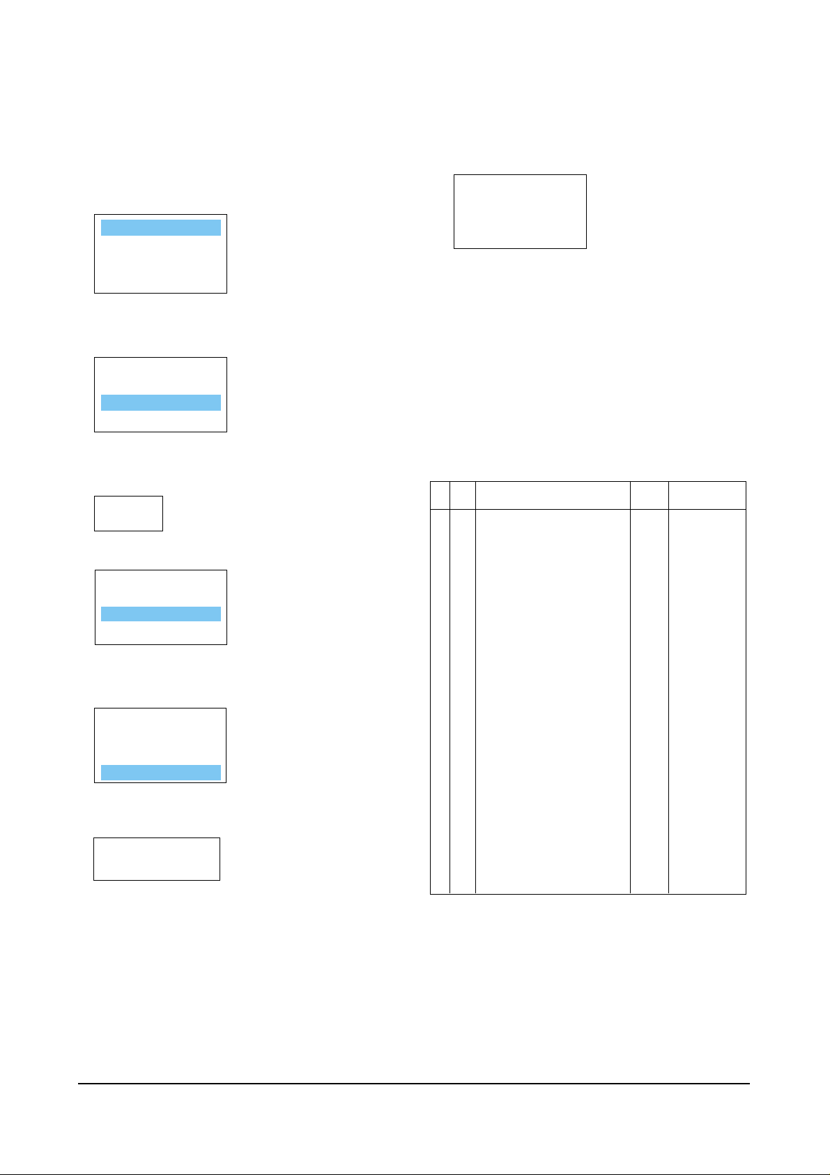
Select a mode to be adjusted, using the channel down key. Example: VCO.
ADJUSTMENT
PATTERN
OPTION
RESET
<---selected (violet)
VCO
71
AGC XX
VCO XX GC XXX
SBT XX BC XX
SCT XX VA XX
SCR XX VS XX
STT XXX HS XX
GG XXX SS XX
BG XXX SVC : MUTE
AGC XX RC XXX
VCO XX
SBT XX BC XX
SCT XX VA XX
SCR XX VS XX
STT XXX HS XX
GG XXX SS XX
BG XXX SVC : MUTE
RC XXX
GC XXX
AGC XX XXX
VCO XX
SBT
SCT
SCR
STT
GG
BG
XX XX
XX VA XX
XX VS XX
XXX HS XX
XXX SS XX
XXX
ADJUSTMENT
PATTERN
OPTION
RESET
RC
GC
BC
SVC : MUTE
XXX
3-1-3 Adjustment in Option Mode
This adjustment is necessary whenever the
EEPROM is replaced. Input data (as marked
on the back cabinet).
Select “SET OPTION” by pressing the
Channel key twice.
Press the Volume +, - keys to enter the set
Option mode.
Press MENU to go back to the factory mode.
Select RESET with channel key.
Press volume + key.
Alignment and Adjustments
3-2 Samsung Electronics
▼
▼
3-1-4 Service Mode Adjustments
1. The Pattern Adjustment is done only in the
factory. Do not attempt to readjust it.
2. Refer to 3-2 for other adjustments.
3. Set OPTION data.
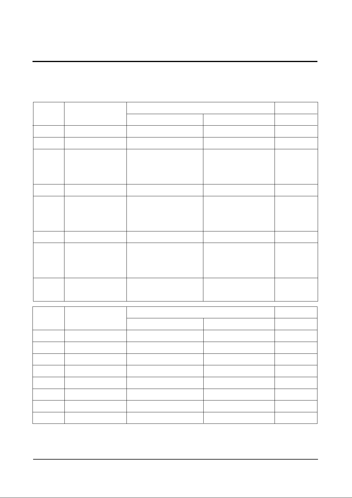
3-1-5 Service Mode Adjustment Ratings
Note : The initial MICOM data values take
effect when IC902 is replaced.
ADJUSTMENT
PATTERN
OPTION
RESET
BYTE 0 : 0 0
BYTE 1 : 0 4
ADJUSTMENT
PATTERN
OPTION
RESET
ADJUSTMENT
PATTERN
OPTION
RESET
ADJUSTMENT
PATTERN
OPTION
RESET
No
Item Function
1 AGC RF AGC Adjustment 0~63 50
2 VCO PIF VCO Adjustment 0~127 63
3 SCT SUB-CONTRAST Adjustment 0~63 48
4 SCR SUB-COLOR Adjustment 0~27 13
5 STT SUB-TINT Adjustment 0~27 7
6 RC RED-CUT OFF Adjustment 0~255 0
7 GC GREEN-CUT OFF Adjustment 0~255 0
8 BC BLUE-CUT OFF Adjustment 0~255 0
Range
Initalized
MICOM Data
ADJUSTMENT
PATTERN
OPTION
RESET
POWER
OFF
9 SVC Input a Horiz line pattern
10 GG GREEN-GAIN Adjustment 0~255 127
11 BG BLUE-GAIN Adjustment 0~255 127
12 SBT SUB-BRIGHTNESS Adjustment 0~63 31
13 VA VERTICAL SIZE Adjustment 0~63 39
14 VS VERTICAL CENTER Adjustment 0 0
15 HS HORIZONTAL Phase Adjustment 0~31 15
16 SS SUB-SHARPNESS Adjustment 0~31 4

Alignment and Adjustments
Samsung Electronics 3-3
3-2 Alignment and Adjustment
3-2-1 General Alignment Instructions
1. Usually, a color TV needs only slight
touch-up adjustment upon installation. Check
the basic characteristics such as picture height,
focus and a horizontal and vertical sync.
2. Observe the picture and check for good back
and white details. There should be no
objectionable color shading: If color shading is
present, demagnetize the receiver. If color
shading persists, perform purity and
convergence adjustments described below.
3. To protect against shock hazard, use an
isolation transformer.
3-2-2 Power Supply Check
Check the following:
A: Power plug is connected; “Stand-by” mode
B: Power On when “Power ON” button is pressed
C: Power On by FBT Each supply is marked on
its lead-in wire. ( )
3-2-3 Focus Adjustment
Adjust the focus control on the FBT for well
defined scanning lines.
3-2-4 Fail Safe Circuit Check (FS) (OPTION)
1. The failsafe check must be the final step in
servicing.
2. Turn the power switch ON and adjust
customer controls for normal operation.
3. Temporarily short pin X to pin R on the main
board (RX06, RX04) with a jumper wire.
Raster will disappear.
4. The TV must remain in this state even after
removing the jumper wire. This shows that
the failsafe circuit is working properly.
5. To recover picture and sound, temporarily
turn off the TV and allow the failsafe circuit
more than 30 seconds to reset. Then switch
power ON to produce normal picture and
sound.
3-2-5 IC902 Replacement
1. When IC902 is replaced, all values are reset to
“Initialized MICOM Data” and readjustment
is necessary.
2. Press the POWER button 10 seconds after
plug-in.
3. To enter the Service Mode, refer to Fig. 3-1
(Service Mode Adjustment).
3-2-6 PIF VCO Adjustment
1. Use a Pattern Generator or an off-air signal.
2. Open pin 11 of Micom (IC901) or one side of
lead pin for R237.
3. Adjust VCO in the service mode to set IC101
Pin 44 (AFT) to 2.5V ± 0.4V.
4. Connect the opened site.
3-2-7 RF-AGC Adjustment
1. Input a PHILLIPS pattern.
2. Set the input signal to 60 dB.
3. Enter into the AGC in the service mode.
4. Adjust AGC until color bar noise disappears.
Alignment and Adjustments
3-4 Samsung Electronics
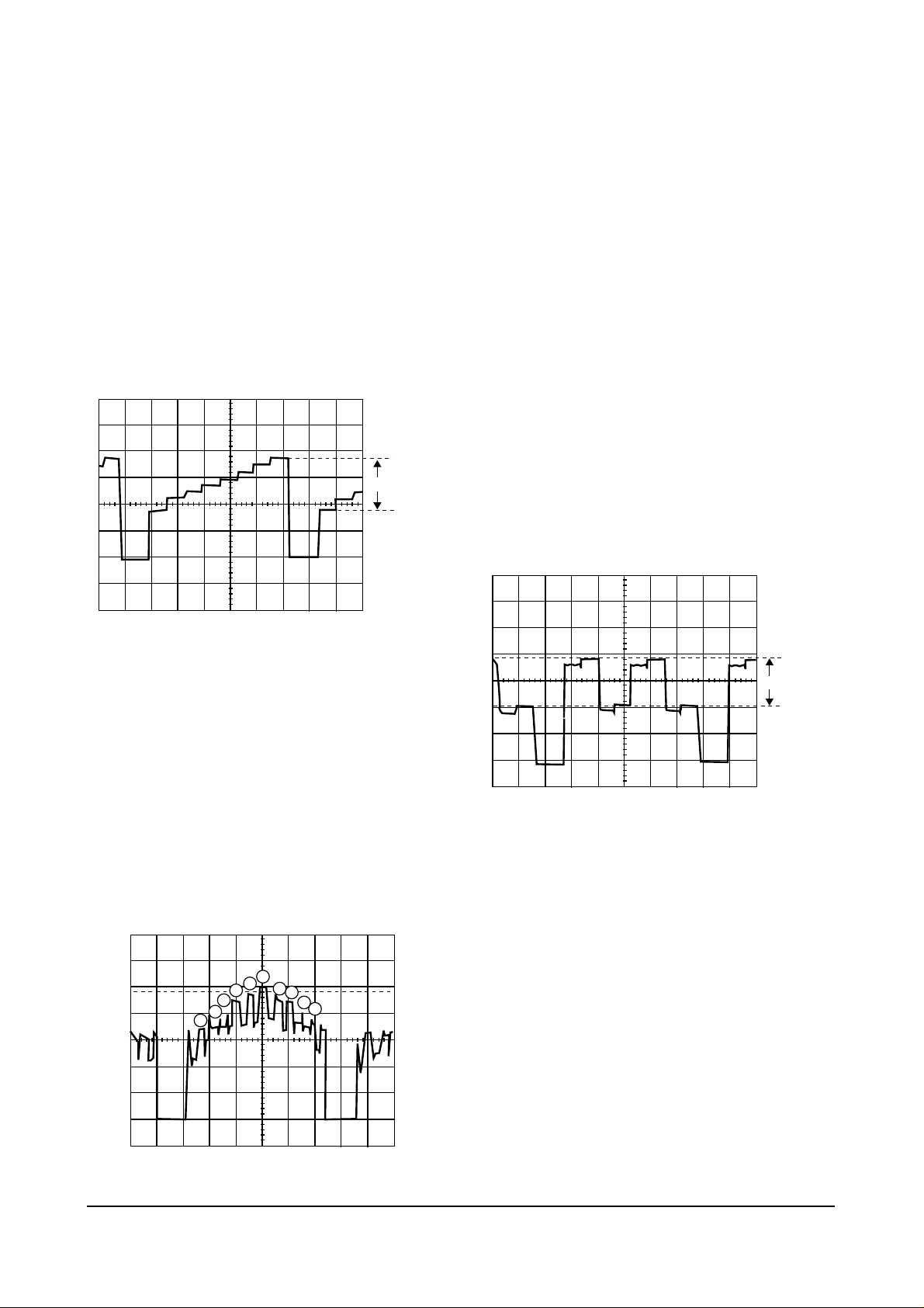
3-2-8 Sub-Contrast Adjustment
1. Input a gray scale pattern. Use a pattern
generator (PM5518).
2. Short D208 to switch off the ABL feed-back.
3. Check CN201 R-OUT with an oscilloscope.
4. Set RC, BC, GC data to 0 in the Service Mode.
5. Adjust SCT to 2.40 ± 0.1Vp-p
6. Remove the short across D208 and restore
ABL.
3-2-9 Sub-Tint Adjustment
1. Input a rainbow pattern.
2. Check CN201 B-OUT with an oscilloscope.
3. Adjust STT in the service mode until the 6th
peak is the highest and the 5th and 7th peaks
have equal heights.
3-2-10 Sub-Color Adjustment
1. Do sub-color adjustment after the SubContrast and Sub-Tint adjustments.
2. D208 should still be shorted. The ABL should
still be switched OFF.
3. Input a color bar pattern. Use a pattern generator (PM5518).
4. Check CN201 R-OUT (use an oscilloscope).
5. Ensure that the RC, GC and BC data are 0.
BG are 140 and GG should be 90.
6. Adjust SCR to 2.4 ± 0.1Vp-p (black and
red levels).
7. Remove the short across D208 and restore
ABL.
2.5V 0.1Vpp
+
_
1
2
3
4
5
6
7
8
9
10
2.4V 0.1Vpp
+
_

Alignment and Adjustments
Samsung Electronics 3-5
3-2-11 White Balance Adjustment
3-2-11 (A) LOW-LIGHT ADJUSTMENTS
1. Input either a lion head or “pure white” color
pattern.
2. Operate the receiver for 30 minutes.
3. Check the data in the service mode:
RC, GC, BC are 0 and SB is 16;
Steps BG are 90 and GG are 140.
4. Enter the horizontal line mode by pressing
the MUTE key.
5. Adjust the screen VR on the FBT until a dim
colored line (red,green or blue) appears on the
screen.
6. After pressing the MUTE key, go to RC,BC or
GC with channel , keys. After putting a
dim colored line (red, green or blue) in the
horizontal line with MUTE key, adjust color
with volume , keys.
7. Exit the horizontal line via the MUTE key.
3-2-11 (B) HIGH-LIGHT ADJUSTMENTS
1. Input a high-light pattern
2. Adjust GG,BG in the Service Mode.
3. Recheck in low light.
3-2-12 Sub-Brightness Adjustment
1. Input a Toshiba pattern.
2. Warm up the receiver for 10 minutes.
3. Enter the Service Mode and set SB to the point
where the 5th point is brighter in the gray
scale.
3-2-13 Vertical Size Adjustment
1. Input a lion head pattern.
2. After the vertical center adjustment, enter into
the service mode.
3. Adjust VA so that the each top and bottom of
the screen is 4.0. If the top and bottom values
are different, adjust VA so that the sum of the
two values is 8.0.
3-2-14 Horizontal Size Adjustment
1. Receive a lion head pattern.
2. Enter into the service mode.
3. Adjust HS to symmetrized right and left.
3-2-15 When CRT Is Replaced
Do the following adjustments after the basic
purity and convergence adjustments.
1. White Balance
2. Sub-brightness
3. Vertical Size
4. Horizontal Size
5. Fail safe (should be the final step).
W
5
4 3
2 1
▼
▼
▼
▼
3-6 Samsung Electronics
BYTE:0
D7
D6
D5
D4
D3
D2
D1
D0
NAME
WIDE
AFT
AUTO
POWER ON
AUTO
SOUND MUTE
TV/Video
AUTO
POWER OFF
CATV
FUNCTION
0
Not Used
Analog (Tuner Input)
Not Used
Sound Mute
(during no signal)
TV/Video
Not Used
AIR/STD/HRC/IRC
1
Used
Digital (1 Chip Input)
Used
No Sound Mute
(during no signal)
Video Only
Power Off
(after 15 minute)
during no signal
AIR/STD/HRC/AFN
REMARK
1 for army
NT Only
3-3 Option Byte Table
Note: The option bytes are adjusted in the Service mode.
BYTE:1
D7
D6
D5
D4
D3
D2
D1
D0
NAME
TURBO
MTS
V-CHIP
FUNCTION
0
No Turbo function
No MTS function
No V-CHIP function
0
Turbo function exists
MTS function exists
V-CHIP function exists
Micom : SZM370TH
REMARK
 Loading...