

SAMSUNG CS667APTRXBWT Service Manual
COLOR TELEVISION RECEIVER
Chassis : SCT55A
Model: CS667APTRX/BWT
COLOR TELEVISION RECEIVER CONTENTS
1.
Precautions
2.
Reference Information
3.
Specifications
4.
Disassembly and Reassembly
5.
Alignment and Adjustment s
6.
Troubleshooting
7.
Exploded View and Parts List
8.
Electric Parts List
9.
Block Diagrams
10.
PCB Layout
11.
Wiring Diagram
12.
Schematic Diagrams

ELECTRONICS
©
Samsung Electronics Co., Ltd. APR. 1999
Printed in Korea
3SCT55A-6715
1. Precautions
1-1 Safety Precautions
1. Be sure that all of the built-in protective
devices are replaced. Restore any missing
protective shields.
2. When reinstalling the chassis and its
assemblies, be sure to restore all protective
devices, including: nonmetallic control knobs
and compartment covers.
3. Make sure that there are no cabinet openings
through which peopleÑparticularly
childrenÑmight insert fingers and contact
dangerous voltages. Such openings include
the spacing between the picture tube and the
cabinet mask, excessively wide cabinet
ventilation slots, and improperly fitted back
covers.
If the measured resistance is less than 1.0
megohm or greater than 5.2 megohms, an
abnormality exists that must be corrected
before the unit is returned to the customer.
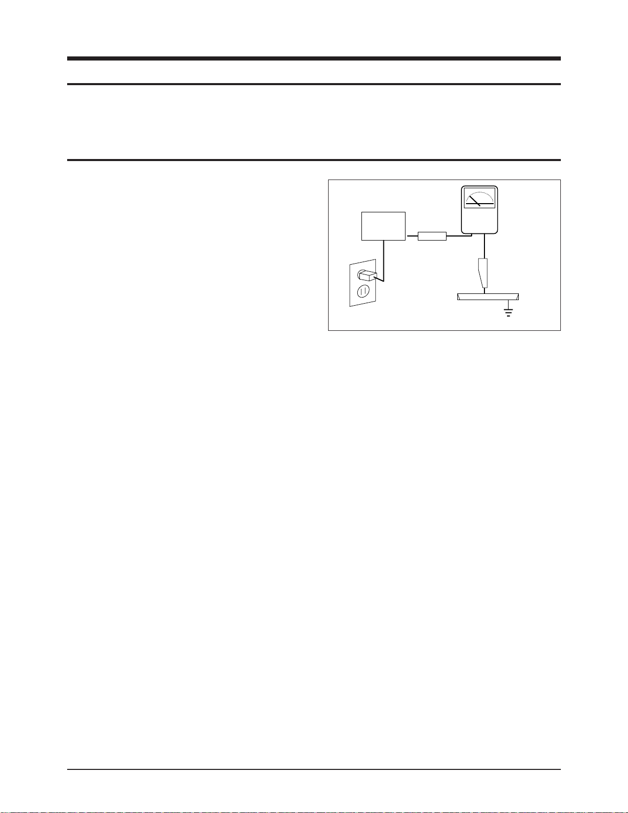
4. Leakage Current Hot Check (Figure 1-1):
Warning: Do not use an isolation
transformer during this test. Use a leakagecurrent tester or a metering system that
complies with American National Standards
Institute (ANIS C101.1, Leakage Current for
Appliances), and Underwriters Laboratories
(UL Publication UL1410, 59.7).
5. With the unit completely reassembled, plug
the AC line cord directly into the power
outlet. With the unitÕs AC switch first in the
ON position and then OFF, measure the
current between a known earth ground (metal
water pipe, conduit, etc.) and all exposed
metal parts, including: antennas, handle
brackets, metal cabinets, screwheads and
control shafts. The current measured should
not exceed 0.5 milliamp. Reverse the powerplug prongs in the AC outlet and repeat the
test.
Fig. 1-1 AC Leakage Test
6. Antenna Cold Check:
With the unitÕs AC plug disconnected from the
AC source, connect an electrical jumper across
the two AC prongs. Connect one lead of the
ohmmeter to an AC prong. Connect the other
lead to the coaxial connector.
7. X-ray Limits:
The picture tube is especially designed to prohibit X-ray emissions. To ensure continued
X-ray protection, replace the picture tube only
with one that is the same type as the original.
Carefully reinstall the picture tube shields and
mounting hardware; these also provide X-ray
protection.
8. High Voltage Limits:
High voltage must be measured each time servicing is done on the B+, horizontal deflection
or high voltage circuits. Correct operation of
the X-ray protection circuits must be
reconfirmed whenever they are serviced.
(X-ray protection circuits also may be called
Òhorizontal disableÓ or Òhold-downÓ.)
Heed the high voltage limits. These include
the XÐray Protection Specifications Label, and
the Product Safety and X-ray Warning Note on
the service data schematic.
Precautions
Samsung Electronics 1-1
LEAKAGE
CURRENT
TESTER
DEVICE
UNDER
TEST
TEST ALL
EXPOSED METAL
SURFACES
2-WIRE CORD
ALSO TEST WITH
PLUG REVERSED
(USING AC ADAPTER
PLUG AS REQUIRED)
EARTH
GROUND
(READING SHOULD
NOT BE ABOVE
0.5mA)
Follow these safety, servicing and ESD precautions to prevent damage and protect against potential
hazards such as electrical shock and X-rays.

1-1 Safety Precautions (Continued)
9. High voltage is maintained within specified
limits by close-tolerance, safety-related
components and adjustments. If the high
voltage exceeds the specified limits, check
each of the special components.
10. Design Alteration Warning:
Never alter or add to the mechanical or
electrical design of this unit. Example: Do not
add auxiliary audio or video connectors. Such
alterations might create a safety hazard. Also,
any design changes or additions will void the
manufacturerÕs warranty.
11. Hot Chassis Warning:
Some TV receiver chassis are electrically
connected directly to one conductor of the AC
power cord. If an isolation transformer is not
used, these units may be safely serviced only
if the AC power plug is inserted so that the
chassis is connected to the ground side of the
AC source.
To confirm that the AC power plug is inserted
correctly, do the following: Using an AC
voltmeter, measure the voltage between the
chassis and a known earth ground. If the
reading is greater than 1.0V, remove the AC
power plug, reverse its polarity and reinsert.
Re-measure the voltage between the chassis
and ground.
12. Some TV chassis are designed to operate with
85 volts AC between chassis and ground,
regardless of the AC plug polarity. These units
can be safely serviced only if an isolation
transformer inserted between the receiver and
the power source.
13. Some TV chassis have a secondary ground
system in addition to the main chassis ground.
This secondary ground system is not
isolated from the AC power line. The two
ground systems are electrically separated by
insulating material that must not be defeated
or altered.
14. Components, parts and wiring that appear to
have overheated or that are otherwise
damaged should be replaced with parts that
meet the original specifications. Always
determine the cause of damage or overheating, and correct any potential hazards.
15. Observe the original lead dress, especially
near the following areas: Antenna wiring,
sharp edges, and especially the AC and high
voltage power supplies. Always inspect for
pinched, out-of-place, or frayed wiring. Do
not change the spacing between components
and the printed circuit board. Check the AC
power cord for damage. Make sure that leads
and components do not touch thermally hot
parts.
16. Picture Tube Implosion Warning:
The picture tube in this receiver employs
Òintegral implosionÓ protection. To ensure
continued implosion protection, make sure
that the replacement picture tube is the same
as the original.
17. Do not remove, install or handle the picture
tube without first putting on shatterproof
goggles equipped with side shields. Never
handle the picture tube by its neck. Some
Òin-lineÓ picture tubes are equipped with a
permanently attached deflection yoke; do not
try to remove such Òpermanently attachedÓ
yokes from the picture tube.
18. Product Safety Notice:
Some electrical and mechanical parts have
special safety-related characteristics which
might not be obvious from visual inspection.
These safety features and the protection they
give might be lost if the replacement component differs from the originalÑeven if the
replacement is rated for higher voltage,
wattage, etc.
Components that are critical for safety are
indicated in the circuit diagram by shading,
( ) or ( ).
Use replacement components that have the
same ratings, especially for flame resistance
and dielectric strength specifications.
A replacement part that does not have the
same safety characteristics as the original
might create shock, fire or other hazards.
Precautions
1-2 Samsung Electronics
!

1-2 Servicing Precautions
1. Servicing precautions are printed on the
cabinet. Follow them.
2. Always unplug the unitÕs AC power cord from
the AC power source before attempting to: (a)
Remove or reinstall any component or
assembly, (b) Disconnect an electrical plug or
connector, (c) Connect a test component in
parallel with an electrolytic capacitor.
3. Some components are raised above the printed
circuit board for safety. An insulation tube or
tape is sometimes used. The internal wiring is
sometimes clamped to prevent contact with
thermally hot components. Reinstall all such
elements to their original position.
4. After servicing, always check that the screws,
components and wiring have been correctly
reinstalled. Make sure that the portion around
the serviced part has not been damaged.
5. Check the insulation between the blades of the
AC plug and accessible conductive parts
(examples: metal panels, input terminals and
earphone jacks).
6. Insulation Checking Procedure: Disconnect the
power cord from the AC source and turn the
power switch ON. Connect an insulation
resistance meter (500V) to the blades of the AC
plug.
The insulation resistance between each blade
of the AC plug and accessible conductive parts
(see above) should be greater than 1 megohm.
7. Never defeat any of the B+ voltage interlocks.
Do not apply AC power to the unit (or any of
its assemblies) unless all solid-state heat sinks
are correctly installed.
8. Always connect a test instrumentÕs ground
lead to the instrument chassis ground before
connecting the positive lead; always remove
the instrumentÕs ground lead last.
Precautions
Samsung Electronics 1-3
Warning1: First read the “Safety Precautions” section of this manual. If some unforeseen circumstance creates a conflict between
the servicing and safety precautions, always follow the safety precautions.
Warning2: An electrolytic capacitor installed with the wrong polarity might explode.

1. Some semiconductor (Òsolid stateÓ) devices
are easily damaged by static electricity. Such
components are called Electrostatically
Sensitive Devices (ESDs); examples include
integrated circuits and some field-effect
transistors. The following techniques will
reduce the occurrence of component damage
caused by static electricity.
2. Immediately before handling any semicon
ductor components or assemblies, drain the
electrostatic charge from your body by
touching a known earth ground. Alternatively,
wear a discharging wrist-strap device. (Be
sure to remove it prior to applying powerÑ
this is an electric shock precaution.)
3. After removing an ESD-equipped assembly,
place it on a conductive surface such as
aluminum foil to prevent accumulation of
electrostatic charge.
4. Do not use freon-propelled chemicals. These
can generate electrical charges that damage
ESDs.
5. Use only a grounded-tip soldering iron when
soldering or unsoldering ESDs.
6. Use only an anti-static solder removal device.
Many solder removal devices are not rated as
Òanti-staticÓ; these can accumulate sufficient
electrical charge to damage ESDs.
7. Do not remove a replacement ESD from its
protective package until you are ready to
install it. Most replacement ESDs are
packaged with leads that are electrically
shorted together by conductive foam,
aluminum foil or other conductive materials.
8. Immediately before removing the protective
material from the leads of a replacement ESD,
touch the protective material to the chassis or
circuit assembly into which the device will be
installed.
9. Minimize body motions when handling
unpackaged replacement ESDs. Motions such
as brushing clothes together, or lifting a foot
from a carpeted floor can generate enough
static electricity to damage an ESD.
Precautions
1-4 Samsung Electronics
1-3 Precautions for Electrostatically Sensitive Devices (ESDs)

Reference Information
Samsung Electronics 2-1
2. Reference Information
2-1 Tables of Abbreviations and Acronyms
A
Ah
Å
dB
dBm
°C
°F
°K
F
G
GHz
g
H
Hz
h
ips
kWh
kg
kHz
kΩ
km
km/h
kV
kVA
kW
I
MHz
Ampere
Ampere-hour
Angstrom
Decibel
Decibel Referenced to One
Milliwatt
Degree Celsius
Degree Fahrenheit
degree Kelvin
Farad
Gauss
Gigahertz
Gram
Henry
Hertz
Hour
Inches Per Second
Kilowatt-hour
Kilogram
Kilohertz
Kilohm
Kilometer
Kilometer Per Hour
Kilovolt
Kilovolt-ampere
Kilowatt
Liter
Megahertz
MV
MW
MΩ
m
µA
µF
µH
µm
µs
µW
mA
mg
mH
mI
mm
ms
mV
nF
Ω
pF
Ib
rpm
rps
s
V
VA
W
Wh
Megavolt
Megawatt
Megohm
Meter
Microampere
Microfarad
Microhenry
Micrometer
Microsecond
Microwatt
Milliampere
Milligram
Millihenry
Milliliter
Millimeter
Millisecond
Millivolt
Nanofarad
Ohm
Picofarad
Pound
Revolutions Per Minute
Revolutions Per Second
Second (Time)
Volt
Volt-ampere
Watt
Watt-hour
Table 2-1 Abbreviations

Reference Information
2-2 Samsung Electronics
Table 2-1 Abbreviations
ABL
AC
ACC
AF
AFC
AFT
AGC
AM
ANSI
APC
APC
A/V
AVC
BAL
BPF
B-Y
CATV
CB
CCD
CCTV
Ch
CRT
CW
DC
DVM
EIA
ESD
ESD
FBP
FBT
FF
FM
FS
GND
G-Y
H
HF
HI-FI
IC
IC
IF
Automatic Brightness Limiter
Alternating Current
Automatic Chroma Control
Audio Frequency
Automatic Frequency Control
Automatic Fine Tuning
Automatic Gain Control
Amplitude Modulation
American National Standards Institute
Automatic Phase Control
Automatic Picture Control
Audio-Video
Automatic Volume Control
Balance
Bandpass Filter
Blue-Y
Community Antenna Television (Cable TV)
Citizens Band
Charge Coupled Device
Closed Circuit Television
Channel
Cathode Ray Tube
Continuous Wave
Direct Current
Digital Volt Meter
Electronics Industries Association
Electrostatic Discharge
Electrostatically Sensitive Device
Feedback Pulse
Flyback Transformer
Flip-Flop
Frequency Modulation
Fail Safe
Ground
Green-Y
High
High-Frequency
High Fidelity
Inductance-Capacitance
Integrated Circuit
Intermediate Frequency
I/O
L
L
LED
LF
MOSFET
MTS
NAB
NEC
NTSC
OSD
PCB
PLL
PWM
QIF
R
RC
RF
R-Y
SAP
SAW
SIF
SMPS
S/N
SW
TP
TTL
TV
UHF
UL
UV
VCD
VCO
VCXO
VHF
VIF
VR
VTR
VTVM
TR
Input/output
Left
Low
Light Emitting Diode
Low Frequency
Metal-Oxide-Semiconductor-Field-Effect-Tr
Multi-channel Television Sound
National Association of Broadcasters
National Electric Code
National Television Systems Committee
On Screen Display
Printed Circuit Board
Phase-Locked Loop
Pulse Width Modulation
Quadrature Intermediate Frequency
Right
Resistor & Capacitor
Radio Frequency
Red-Y
Second Audio Program
Surface Acoustic Wave(Filter)
Sound Intermediate Frequency
Switching Mode Power Supply
Signal/Noise
Switch
Test Point
Transistor Transistor Logic
Television
Ultra High Frequency
Underwriters Laboratories
Ultraviolet
Variable-Capacitance Diode
Voltage Controlled Oscillator
Voltage Controlled Crystal Oscillator
Very High Frequency
Video Intermediate Frequency
Variable Resistor
Video Tape Recorder
Vacuum Tube Voltmeter
Transistor

Reference Information
Samsung Electronics 2-3
2-1 Tables of Abbreviations and Acronyms
100 Series .................................................................................................................................................... IF processing
200 Series ..............................................................................................................................Video, Chroma Processing
300 Series ........................................................................................................................................... Vertical Deflection
400 Series ...................................................................................................................................... Horizontal deflection
500 Series ..................................................................................................................................... CRT Drive Processing
600 Series ............................................................................................................................................ Sound Processing
700 Series ............................................................................................................................. A/V Switching Processing
800 Series ................................................................................................................................. AC Input Power Supply
900 Series ............................................................................................................................................... MICOM Section
RT, CT, ICT ....................................................................................................................................... TELETEXT Section
RC, CC, HC, SWY ............................................................................................................. SNAP-IN Section (Control)
RV,CV,LV,QV ............................................................................................................................................... V/M Section
RJ,CJ,LJ,DJ,ICJ ....................................................................................................................................... NICAM Section
RP,CP,LP,XP,ICP ............................................................................................................................................ PIP Section
RC,CC,DZC,QC ........................................................................................................................... COMB Filter Section
RP,PD .......................................................................................................................................... POWER-S/W Section
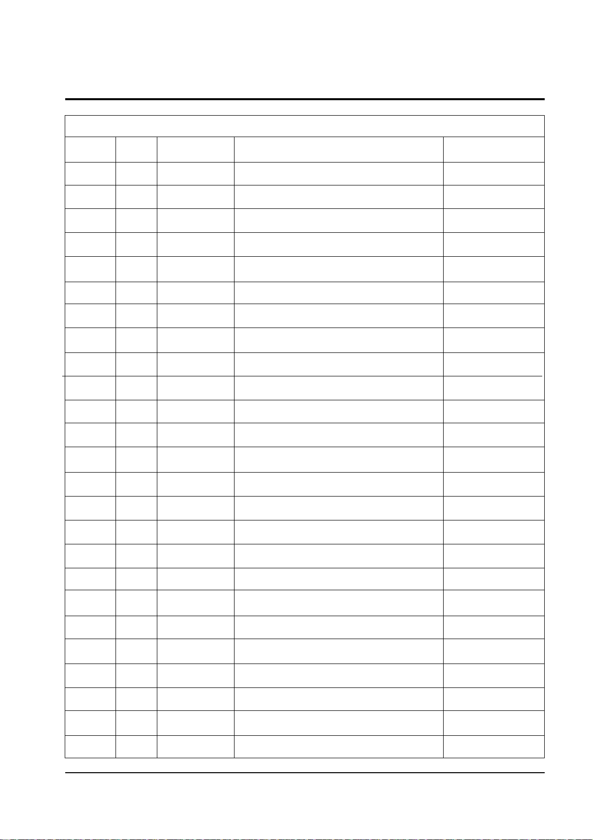
2-2 IC Line Up
Table 2 - 1 IC Line - Up
Reference Information
2-4 Samsung Electronics
Loc No.
IC201
IC203
IC205
IC206
IC207
IC208
IC301
IC401
IC501
IC502
IC503
IC504
IC505
IC6001
IC6002
IC6003
IC6004
IC601
IC701
IC801
IC802
IC901
IC902
IC903
IC904
Specification
TDA8375
TDA9177
TEA5114A
TEA5114A
TEA5114A
TDA9170
LA7845
MC4558C
TDA6101Q
TDA6101Q
TDA6101Q
MC4558C
SPK101T
TDA9875/9870
TDA9808
TDA7050
MC4558C
TDA7297
CXA1855S
STR-S6709
LTV817B
Z89313(Z90341)
KIA7042P
PQ09RF1
KA7808
Remarks
N3 VERSION
SCART OPTION
TTX/OSD
PIP/TTX
POWER
POWER
CRT
CRT
CRT
CRT
CRT
AUDIO MODULE
AUDIO MODULE
AUDIO MODULE
AUDIO MODULE
POWER
POWER
Description
ONE CHIP TV PROCESSOR
LINE TRANSIENT IMPROVEMENT IC (LTI BOOSTER)
R/G/B SWITCHING IC
R/G/B SWITCHING IC
R/G/B SWITCHING IC
YUV PICTURE IMPROVEMENT PROCESSOR
VERTICAL AMP
OP AMPLIFIER (EW AMPLIFIER)
VIDEO OUTPUT AMPLIFIER
VIDEO OUTPUT AMPLIFIER
VIDEO OUTPUT AMPLIFIER
OP AMPLIFIER (TILT AMPLIFIER)
SPOT KILLER HYBRID IC
DIGITAL TV SOUND PROCESSOR
VIF/SIF PROCESSOR (SIF PROCESSOR)
2-CHANNEL HEADPHONE AMPLIFIER
OP AMPLIFIER (AUDIO AMPLIFIER)
SOUND AMP
AUDIO/VIDEO SWITCHING IC
SMPS CONTROL IC
PHOTO COUPLER
MICRO PROCESSOR
RESET IC
9V SWITCHABLE REGULATOR
8V REGULATOR
No.
1
2
3
4
5
6
7
8
9
10
11
12
13
14
15
16
17
18
19
20
21
22
23
24
25
Reference Information
Samsung Electronics 2-5
Option : OSD Language
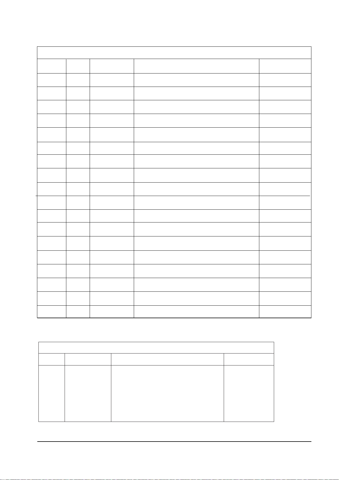
Table 2 - 1 IC Line - Up (Continued)
Loc No.
IC905
IC906
IC907
IC908
IC909
IC910
ICP03
ICP05
ICP06
IC101
IC202
IC203
ICT01
ICP02
ICP01
ICP04
ICP07
ICP08
Specification
KA7812A
KA7805A
KA7808
24C08
KA7805A
KA7805A
TDA9160A
SAB9077H
548262
PAP102
TDA4665
TDA8395P
SAA528IP/E
TDA9808
PAP101
TDA3504
KIA7042P
TDA4665T
Remarks
PIP MODULE
PIP MODULE
PIP MODULE
SECAM MODULE
SECAM MODULE
PIP MODULE
PIP MODULE
PIP MODULE
PIP MODULE
PIP MODULE
Description
12V REGULATOR
5V REGULATOR
8V REGULATOR
E2PROM
5V REGULATOR
5V REGULATOR
PAL/NTSC/SECAM DECODER AND SYNC PROCESSOR
PIP CONTROLLER
MEMORY-2M
IF PRE-AMP HYBRID IC
BASE BAND DELAY LINE
SECAM DECODER
TELETEXT
VIF/SIF-DETECTOR
IF PRE-AMP HYBRID IC
RGB-MATRIX
RESET IC
BASE BAND DELAY LINE
No.
26
27
28
29
30
31
32
33
34
35
36
37
38
39
40
41
42
43
Description
ENG/ARAB/FRENCH/CHINESE/
MALAYSIA/INDONESIA/VIETNAM/
THAI/RUSSIAN/CROATIA/BULGARIA/
POLAND/ROMANIA/CZECH/TURKEY/HUNGARY
Remarks
2-TUNER
MULTI-PIP
MULTI-LANGUAGE
Specification
SZM-162M
Loc No.
IC901
Table 2-2
Specifications
Samsung Electronics 3-1
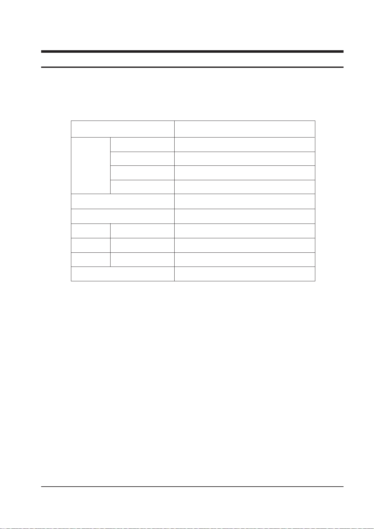
3. Specifications
Model
TUNING
SYSTEM COLOUR
SOUND
NICAM
ANTENNA IMPEDANCE
SCREEN SIZE
POWER REQUIREMENTS
FREQUENCY
PROGRAMME CHANNEL
761A/3001A
Frequency Synthesizer
PAL, SECAM, NTSC3.58, NTSC4.43
B/G, D/K, I,M
B/G,I
75 ohm unbalanced coaxial
70.8 cm
Main voltage : 220V/230V/240V~
Range : 100 - 260V~
50/60Hz
100 channels
Specifications are subject to change.
Disassembly and Reassembly
Samsung Electronics 4-1
4. Disassembly and Reassembly
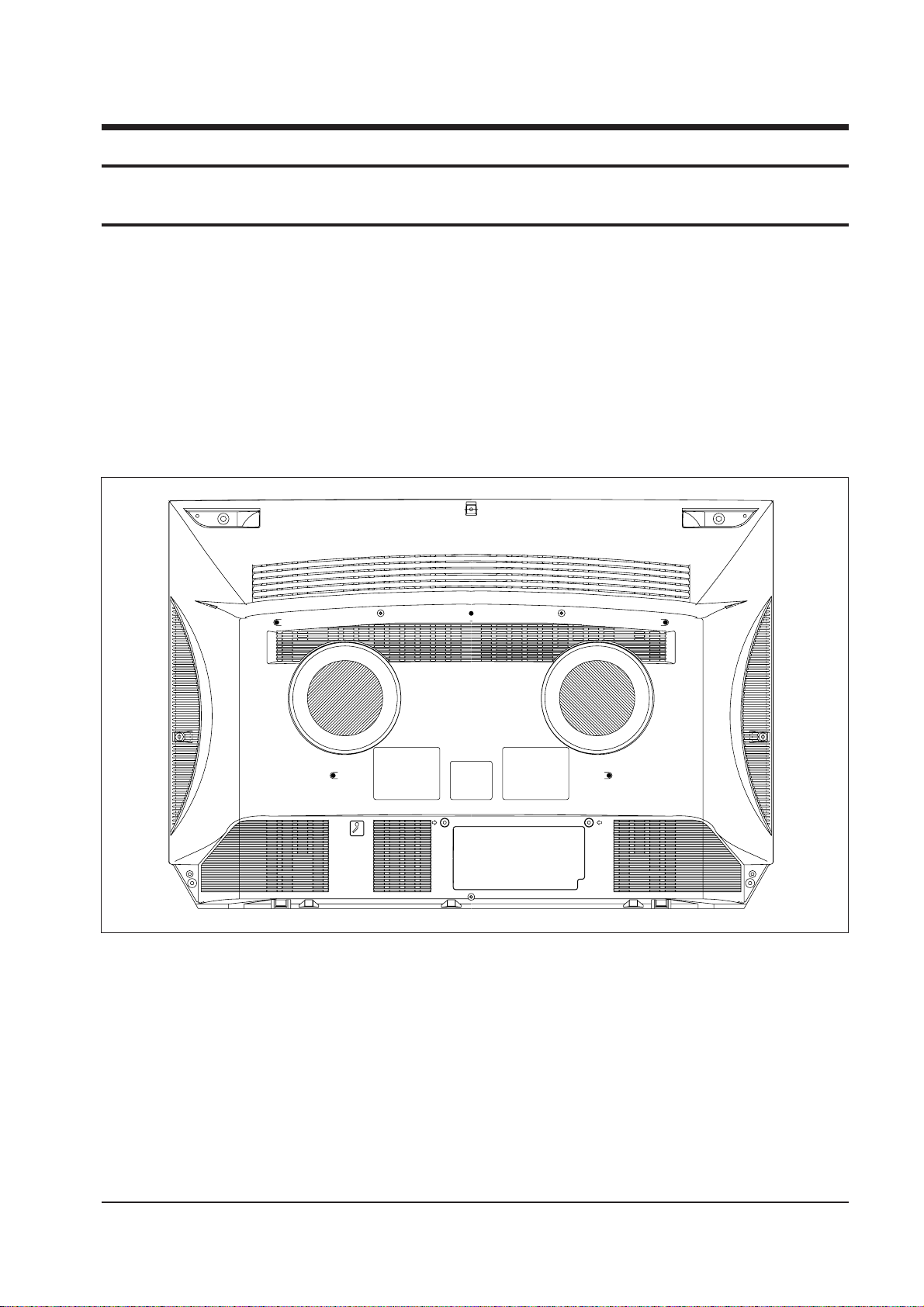
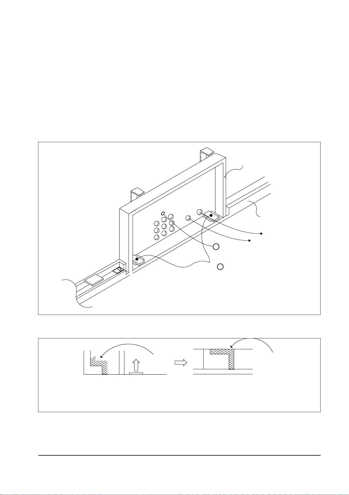
4-1 Cabinet
1. Remove 9 screws located on the side of the cabinet.
2. Pull the Main Assembly backwards to remove.
3. To reassemble, place the receiver on a flat surface and repeat the sequence
in reverse order.
4. To check that that the Chassis Assembly is installed correctly, attempt to
pull if from the front cabinet.
Fig. 4-1
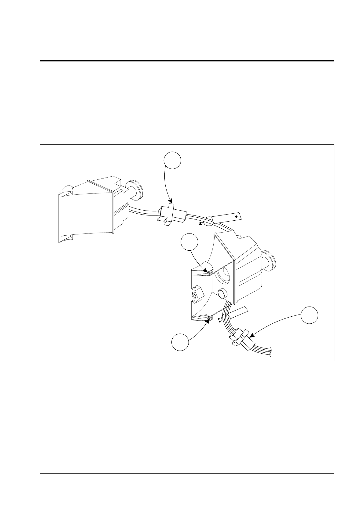
4-2 Speaker
1. Separate Connectors (a), (b).
2. Separate wires from twist-lock.
3. Remove 2 screws, (c).
4. To reassemble, repeat the sequence in reverse order.
Disassembly and Reassembly
4-2 Samsung Electronics
a
c
c
b
Fig. 4-2
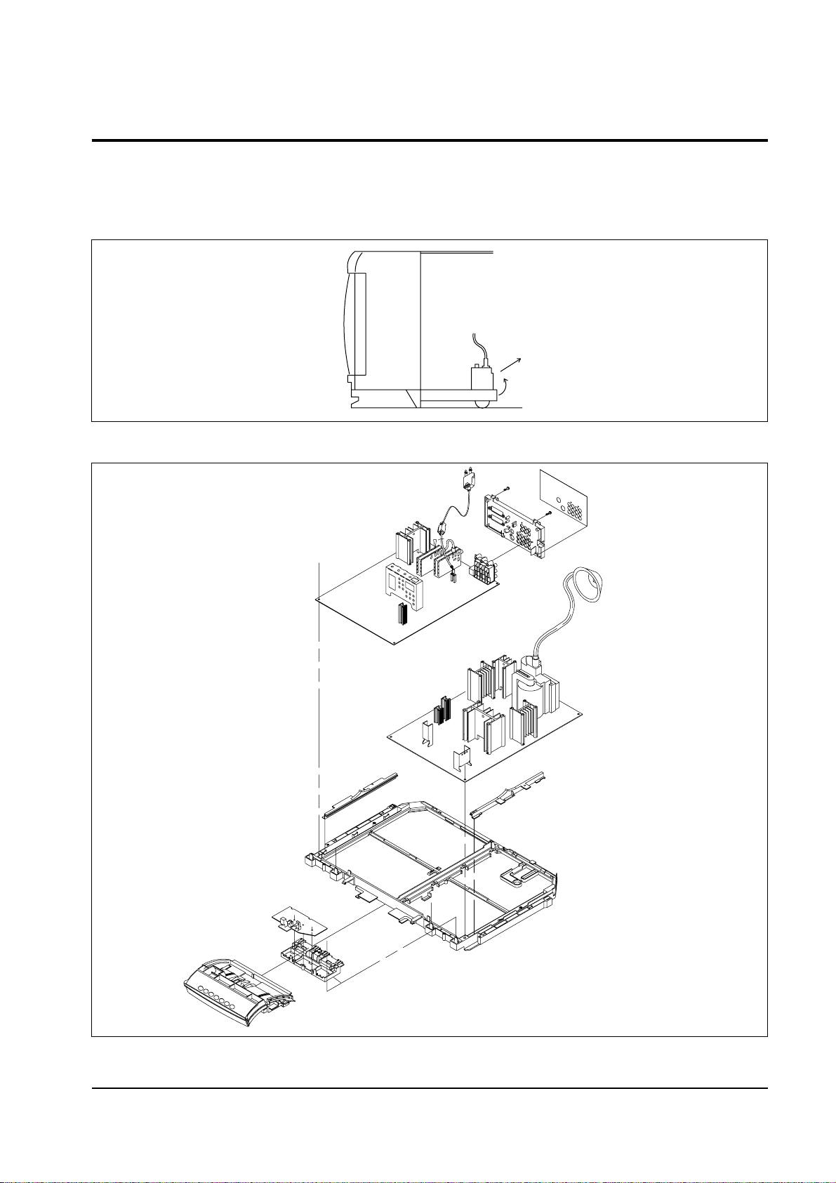
4-3 Chassis Assembly
4-3-1 Removal from Front Cabinet
1. Lift and pull back the chassis mounting.
Disassembly and Reassembly
Samsung Electronics 4-3
Fig. 4-3
Fig. 4-4
Disassembly and Reassembly
4-4 Samsung Electronics
4-3-2 Terminal Board
Removal
1. Pull the power cord to the left and remove it.
2. Remove 1 screw ( a).
3. lift up the 2 brackets( b). Separate the terminal board from the chassis mount.
4. To reassemble, refer to Fig. 4-6.
BRACKET
TERMINAL-BOARD
HOLDER-CHASSIS
a
b
WIRELESS H/P-JACK
+
+
S-VHS JACK
Fig. 4-6
Fig. 4-5
Insert
" " Insert on the left and right bottom of the terminal board, into
" " hole on the holder chassis.
L
L
L
L
Disassembly and Reassembly
Samsung Electronics 4-5
4-3-3 PCB
Removal
1. Refer to the Fig. 4-4.
2. Remove the wire (1P) from the chassis mounting.
3. Pull the PCB guides backwards.
4. Lift both edges of the PCB and pull out.
Disassembly
1. Ensure that the PCB is well positioned in the PCB guides.
2. The power cord must not touch the heat-sink, D73.
3. The PCB guide is part of the chassis mounting ; if a new PCB guide is needed,
the complete chassis mounting must be replaced.
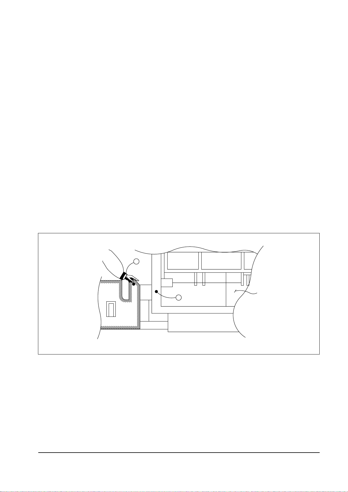
4-3-4 SNAPIN Removal
a
b
SNAPIN-CONTROL
Fig. 4-7 Press the SNAPIN (b) with thumb ; pull the left holder-bracket (a) with index finger
Disassembly and Reassembly
4-6 Samsung Electronics
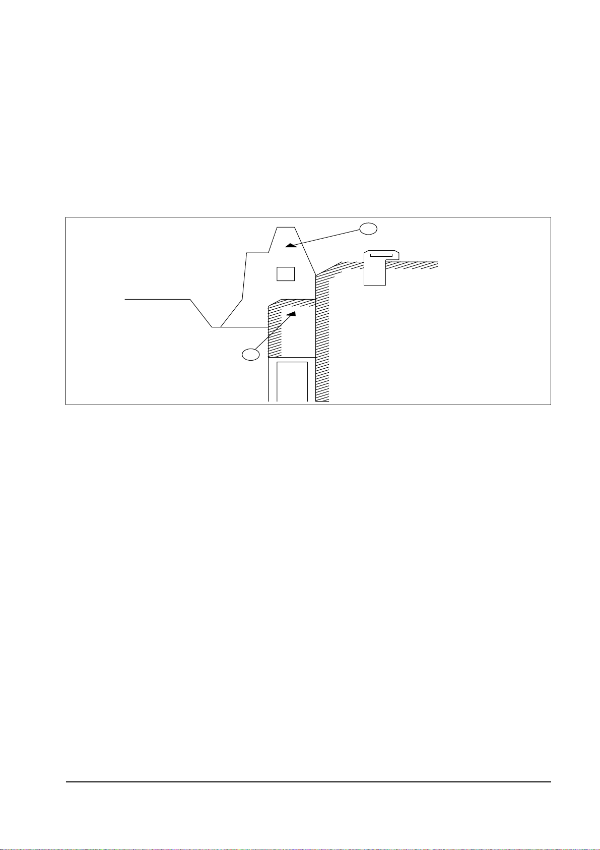
4-3-5 Chassis Reassembly
1. Close the SNAPIN door.
2. Place the chassis bracket (b) onto (a) on the bottom of the cabinet.
3. Push the bracket into the hole (a) until a ÒclickÓ is heard.
4. Check that the SNAPIN door opens and closes.
a
b
HOLDER-CHASSIS
F/CABINET
Fig. 4-8

Alignment and Adjustments
Samsung Electronics 5-1
5. Alignment and Adjustments
5-1 General Alignment Instructions
1. Usually, a color TV-VCR needs only slight
touch-up adjustment upon installation. Check
the basic characteristics such as height,
horizontal and vertical sync and focus.
2. Observe the picture for good black and white
details. There should be no objectionable
color shading; if color shading is present,
demagnetize, perform purity and convergence
adjustments described below.
3. Use the specified test equipment or its
equivalent.
4. Correct impedance matching is essential.
5. Avoid overload. Excessive signal from a sweep
generator might overload the front-end of the
TV. When inserting signal markers, do not
allow the marker generator to distort test
results.
6. Connect the TV only to an AC power source
with voltage and frequency as specified on the
backcover nameplate.
7. Do not attempt to connect or disconnect any
wires while the TV is turned on. Make sure
that the power cord is disconnected before
replacing any parts.
8. To protect against shock hazard, use an isolation transformer.
5-2 Automatic Degaussing
A degaussing coil is mounted around the picture
tube, so that external degaussing after moving
the TV should be unnecessary. But the receiver must be properly degaussed upon installation.
The degaussing coil operates for about 1
second after the power is switched ON. If the
set is moved or turned in a different direction,
the power should be OFF for at least 10
minutes.
If the chassis or parts of the cabinet become
magnetized, poor color purity will result. If
this happens, use an external degaussing coil.
Slowly move the degaussing coil around the
faceplate of the picture tube and the sides and
front of the receiver. Slowly withdraw the coil
to a distance of about 6 feet before turning
power OFF.
If color shading persists, perform the
following Color Purity and Convergence
adjustments.
5-3 High Voltage Check
CAUTION: There is no high voltage
adjustment on this chassis. The B+ power
supply should be +130 volts (with full
color- bar input and normal picture level).
1. Connect a digital voltmeter to the second
anode of the picture tube.
2. Turn on the TV. Set the Brightness and
Contrast controls to minimum (zero beam
current).
3. Adjust the Brightness and contrast controls to
both extremes. Ensure that the high voltage
does not exceed 32 KV under any conditions.
 Loading...