

Page 1

COLOR TELEVISION RECEIVER
Chassis : K55A(P)
Model : CS29Z6HPGX/BWT
COLOR TELEVISION RECEIVER CONTENTS
Precautions
Reference Information
Specifications
Alignment and Adjustments
Troubleshooting
Exploded Views and Parts List
Electrical Parts List
Block Diagrams
Schematic Diagrams
1.
2.
3.
4.
5.
6.
7.
8.
9.
Page 2

ELECTRONICS
© Samsung Electronics Co., Ltd. Jan. 2003
Printed in Korea
AA82-00315A
Page 3
1. Precautions
1-1 Safety Precautions
1. Be sure that all of the built-in protective
devices are replaced. Restore any missing
protective shields.
2. When reinstalling the chassis and its
assemblies, be sure to restore all protective
devices, including: nonmetallic control knobs
and compartment covers.
3. Make sure that there are no cabinet openings
through which people—particularly
children—might insert fingers and contact
dangerous voltages. Such openings include
the spacing between the picture tube and the
cabinet mask, excessively wide cabinet
ventilation slots, and improperly fitted back
covers.
If the measured resistance is less than 1.0
megohm or greater than 5.2 megohms, an
abnormality exists that must be corrected
before the unit is returned to the customer.
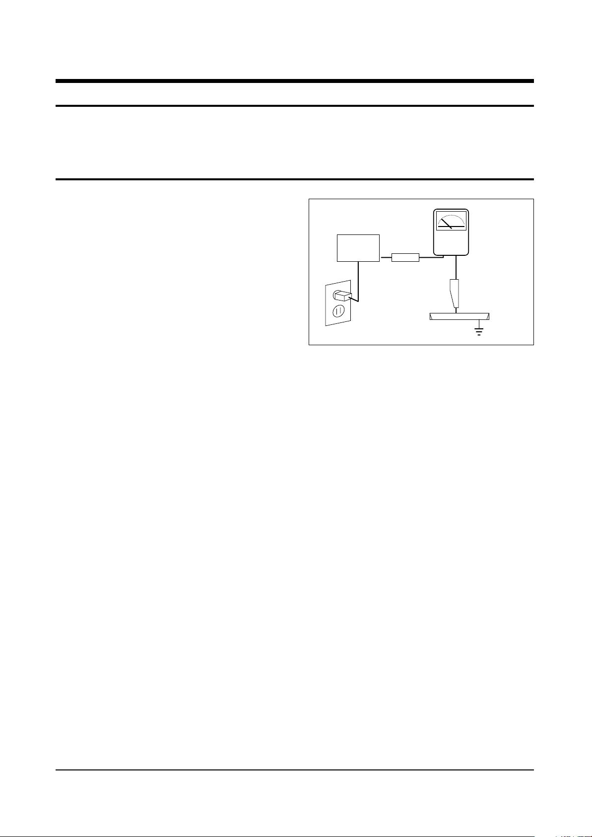
4. Leakage Current Hot Check (Figure 1-1):
Warning: Do not use an isolation
transformer during this test. Use a leakagecurrent tester or a metering system that
complies with American National Standards
Institute (ANIS C101.1, Leakage Current for
Appliances), and Underwriters Laboratories
(UL Publication UL1410, 59.7).
5. With the unit completely reassembled, plug
the AC line cord directly into the power
outlet. With the unit’s AC switch first in the
ON position and then OFF, measure the
current between a known earth ground (metal
water pipe, conduit, etc.) and all exposed
metal parts, including: antennas, handle
brackets, metal cabinets, screwheads and
control shafts. The current measured should
not exceed 0.5 milliamp. Reverse the powerplug prongs in the AC outlet and repeat the
test.
Fig. 1-1 AC Leakage Test
6. Antenna Cold Check:
With the unit’s AC plug disconnected from the
AC source, connect an electrical jumper across
the two AC prongs. Connect one lead of the
ohmmeter to an AC prong. Connect the other
lead to the coaxial connector.
7. X-ray Limits:
The picture tube is especially designed to
prohibit X-ray emissions. To ensure continued
X-ray protection, replace the picture tube only
with one that is the same type as the original.
Carefully reinstall the picture tube shields and
mounting hardware; these also provide X-ray
protection.
8. High Voltage Limits:
High voltage must be measured each time
servicing is done on the B+, horizontal
deflection or high voltage circuits.
Correct operation of the X-ray protection
circuits must be reconfirmed whenever they
are serviced.
(X-ray protection circuits also may be called
“horizontal disable” or “hold-down”.)
Heed the high voltage limits. These include
the X–ray Protection Specifications Label, and
the Product Safety and X-ray Warning Note on
the service data schematic.
Precautions
Samsung Electronics 1-1
LEAKAGE
CURRENT
TESTER
DEVICE
UNDER
TEST
TEST ALL
EXPOSED METAL
SURFACES
2-WIRE CORD
ALSO TEST WITH
PLUG REVERSED
(USING AC ADAPTER
PLUG AS REQUIRED)
EARTH
GROUND
(READING SHOULD
NOT BE ABOVE
0.5mA)
Follow these safety, servicing and ESD precautions to prevent damage and protect against potential
hazards such as electrical shock and X-rays.
Page 4

1-1 Safety Precautions (Continued)
9. High voltage is maintained within specified
limits by close-tolerance, safety-related
components and adjustments. If the high
voltage exceeds the specified limits, check
each of the special components.
10. Design Alteration Warning:
Never alter or add to the mechanical or
electrical design of this unit. Example: Do not
add auxiliary audio or video connectors. Such
alterations might create a safety hazard. Also,
any design changes or additions will void the
manufacturer’s warranty.
11. Hot Chassis Warning:
Some TV receiver chassis are electrically
connected directly to one conductor of the AC
power cord. If an isolation transformer is not
used, these units may be safely serviced only
if the AC power plug is inserted so that the
chassis is connected to the ground side of the
AC source.
To confirm that the AC power plug is inserted
correctly, do the following: Using an AC
voltmeter, measure the voltage between the
chassis and a known earth ground. If the
reading is greater than 1.0V, remove the AC
power plug, reverse its polarity and reinsert.
Re-measure the voltage between the chassis
and ground.
12. Some TV chassis are designed to operate with
85 volts AC between chassis and ground,
regardless of the AC plug polarity. These units
can be safely serviced only if an isolation
transformer inserted between the receiver and
the power source.
13. Some TV chassis have a secondary ground
system in addition to the main chassis ground.
This secondary ground system is not
isolated from the AC power line. The two
ground systems are electrically separated by
insulating material that must not be defeated
or altered.
14. Components, parts and wiring that appear to
have overheated or that are otherwise
damaged should be replaced with parts that
meet the original specifications. Always
determine the cause of damage or
overheating, and correct any potential
hazards.
15. Observe the original lead dress, especially
near the following areas: Antenna wiring,
sharp edges, and especially the AC and high
voltage power supplies. Always inspect for
pinched, out-of-place, or frayed wiring. Do
not change the spacing between components
and the printed circuit board. Check the AC
power cord for damage. Make sure that leads
and components do not touch thermally hot
parts.
16. Picture Tube Implosion Warning:
The picture tube in this receiver employs
“integral implosion” protection. To ensure
continued implosion protection, make sure
that the replacement picture tube is the same
as the original.
17. Do not remove, install or handle the picture
tube without first putting on shatterproof
goggles equipped with side shields. Never
handle the picture tube by its neck. Some
“in-line” picture tubes are equipped with a
permanently attached deflection yoke; do not
try to remove such “permanently attached”
yokes from the picture tube.
18. Product Safety Notice:
Some electrical and mechanical parts have
special safety-related characteristics which
might not be obvious from visual inspection.
These safety features and the protection they
give might be lost if the replacement
component differs from the original—even if
the replacement is rated for higher voltage,
wattage, etc.
Components that are critical for safety are
indicated in the circuit diagram by shading,
( ) or ( ).
Use replacement components that have the
same ratings, especially for flame resistance
and dielectric strength specifications.
A replacement part that does not have the
same safety characteristics as the original
might create shock, fire or other hazards.
Precautions
1-2 Samsung Electronics
!
Page 5

1-2 Servicing Precautions
1. Servicing precautions are printed on the
cabinet. Follow them.
2. Always unplug the unit’s AC power cord from
the AC power source before attempting to:
(a) Remove or reinstall any component or
assembly, (b) Disconnect an electrical plug or
connector, (c) Connect a test component in
parallel with an electrolytic capacitor.
3. Some components are raised above the printed
circuit board for safety. An insulation tube or
tape is sometimes used. The internal wiring is
sometimes clamped to prevent contact with
thermally hot components. Reinstall all such
elements to their original position.
4. After servicing, always check that the screws,
components and wiring have been correctly
reinstalled. Make sure that the portion around
the serviced part has not been damaged.
5. Check the insulation between the blades of the
AC plug and accessible conductive parts
(examples: metal panels, input terminals and
earphone jacks).
6. Insulation Checking Procedure: Disconnect the
power cord from the AC source and turn the
power switch ON. Connect an insulation
resistance meter (500V) to the blades of the AC
plug.
The insulation resistance between each blade
of the AC plug and accessible conductive parts
(see above) should be greater than 1 megohm.
7. Never defeat any of the B+ voltage interlocks.
Do not apply AC power to the unit (or any of
its assemblies) unless all solid-state heat sinks
are correctly installed.
8. Always connect a test instrument’s ground
lead to the instrument chassis ground before
connecting the positive lead; always remove
the instrument’s ground lead last.
Precautions
Samsung Electronics 1-3
Warning1: First read the “Safety Precautions” section of this manual. If some unforeseen circumstance creates a conflict between
the servicing and safety precautions, always follow the safety precautions.
Warning2: An electrolytic capacitor installed with the wrong polarity might explode.
Page 6

1. Some semiconductor (“solid state”) devices
are easily damaged by static electricity. Such
components are called Electrostatically
Sensitive Devices (ESDs); examples include
integrated circuits and some field-effect
transistors. The following techniques will
reduce the occurrence of component damage
caused by static electricity.
2. Immediately before handling any semicon
ductor components or assemblies, drain the
electrostatic charge from your body by
touching a known earth ground. Alternatively,
wear a discharging wrist-strap device. (Be
sure to remove it prior to applying power—
this is an electric shock precaution.)
3. After removing an ESD-equipped assembly,
place it on a conductive surface such as
aluminum foil to prevent accumulation of
electrostatic charge.
4. Do not use freon-propelled chemicals. These
can generate electrical charges that damage
ESDs.
5. Use only a grounded-tip soldering iron when
soldering or unsoldering ESDs.
6. Use only an anti-static solder removal device.
Many solder removal devices are not rated as
“anti-static”; these can accumulate sufficient
electrical charge to damage ESDs.
7. Do not remove a replacement ESD from its
protective package until you are ready to
install it. Most replacement ESDs are
packaged with leads that are electrically
shorted together by conductive foam,
aluminum foil or other conductive materials.
8. Immediately before removing the protective
material from the leads of a replacement ESD,
touch the protective material to the chassis or
circuit assembly into which the device will be
installed.
9. Minimize body motions when handling
unpackaged replacement ESDs. Motions such
as brushing clothes together, or lifting a foot
from a carpeted floor can generate enough
static electricity to damage an ESD.
Precautions
1-4 Samsung Electronics
1-3 Precautions for Electrostatically Sensitive Devices (ESDs)
CAUTION
These servicing instructions are for use by
qualified service personnel only.
To reduce the risk of electric shock do not
perform any servicing other than that
contained in the operating instructions unless
you are qualified to do so.
Page 7

Reference Information
Samsung Electronics 2-1
2. Reference Information
2-1 Tables of Abbreviations and Acronyms
A
Ah
Å
dB
dBm
°C
°F
°K
F
G
GHz
g
H
Hz
h
ips
kWh
kg
kHz
kΩ
km
km/h
kV
kVA
kW
I
MHz
Ampere
Ampere-hour
Angstrom
Decibel
Decibel Referenced to One
Milliwatt
Degree Celsius
Degree Fahrenheit
degree Kelvin
Farad
Gauss
Gigahertz
Gram
Henry
Hertz
Hour
Inches Per Second
Kilowatt-hour
Kilogram
Kilohertz
Kilohm
Kilometer
Kilometer Per Hour
Kilovolt
Kilovolt-ampere
Kilowatt
Liter
Megahertz
MV
MW
MΩ
m
µA
µF
µH
µm
µs
µW
mA
mg
mH
mI
mm
ms
mV
nF
Ω
pF
Ib
rpm
rps
s
V
VA
W
Wh
Megavolt
Megawatt
Megohm
Meter
Microampere
Microfarad
Microhenry
Micrometer
Microsecond
Microwatt
Milliampere
Milligram
Millihenry
Milliliter
Millimeter
Millisecond
Millivolt
Nanofarad
Ohm
Picofarad
Pound
Revolutions Per Minute
Revolutions Per Second
Second (Time)
Volt
Volt-ampere
Watt
Watt-hour
Table 2-1 Abbreviations
Page 8

Reference Information
2-2 Samsung Electronics
Table 2-2 Table of Acronyms
ABL
AC
ACC
AF
AFC
AFT
AGC
AM
ANSI
APC
APC
A/V
AVC
BAL
BPF
B-Y
CATV
CB
CCD
CCTV
Ch
CRT
CW
DC
DVM
EIA
ESD
ESD
FBP
FBT
FF
FM
FS
GND
G-Y
H
HF
HI-FI
IC
IC
IF
Automatic Brightness Limiter
Alternating Current
Automatic Chroma Control
Audio Frequency
Automatic Frequency Control
Automatic Fine Tuning
Automatic Gain Control
Amplitude Modulation
American National Standards Institute
Automatic Phase Control
Automatic Picture Control
Audio-Video
Automatic Volume Control
Balance
Bandpass Filter
Blue-Y
Community Antenna Television (Cable TV)
Citizens Band
Charge Coupled Device
Closed Circuit Television
Channel
Cathode Ray Tube
Continuous Wave
Direct Current
Digital Volt Meter
Electronics Industries Association
Electrostatic Discharge
Electrostatically Sensitive Device
Feedback Pulse
Flyback Transformer
Flip-Flop
Frequency Modulation
Fail Safe
Ground
Green-Y
High
High-Frequency
High Fidelity
Inductance-Capacitance
Integrated Circuit
Intermediate Frequency
I/O
L
L
LED
LF
MOSFET
MTS
NAB
NEC
NTSC
OSD
PCB
PLL
PWM
QIF
R
RC
RF
R-Y
SAP
SAW
SIF
SMPS
S/N
SW
TP
TTL
TV
UHF
UL
UV
VCD
VCO
VCXO
VHF
VIF
VR
VTR
VTVM
TR
Input/output
Left
Low
Light Emitting Diode
Low Frequency
Metal-Oxide-Semiconductor-Field-Effect-Tr
Multi-channel Television Sound
National Association of Broadcasters
National Electric Code
National Television Systems Committee
On Screen Display
Printed Circuit Board
Phase-Locked Loop
Pulse Width Modulation
Quadrature Intermediate Frequency
Right
Resistor & Capacitor
Radio Frequency
Red-Y
Second Audio Program
Surface Acoustic Wave(Filter)
Sound Intermediate Frequency
Switching Mode Power Supply
Signal/Noise
Switch
Test Point
Transistor Transistor Logic
Television
Ultra High Frequency
Underwriters Laboratories
Ultraviolet
Variable-Capacitance Diode
Voltage Controlled Oscillator
Voltage Controlled Crystal Oscillator
Very High Frequency
Video Intermediate Frequency
Variable Resistor
Video Tape Recorder
Vacuum Tube Voltmeter
Transistor
Page 9
Reference Information
Samsung Electronics 2-3
Table 2 - 3 IC Line - Up
NO
1
2
IN NAME
SDA555X-OTP
DDRI001A
TCPS300PC16B(S)
DETECTOR;7027
78R05
FJL6920YDTU
GSIB660
78R05
7269A
KA5Q1565RF
LA7845
24WC16
393, DIP, 8P
78R09
MSP3411G-B11
TCLS3101PD16A(S)
7812A
431
7025
78RM33
BUZ73A
78RM33
7027
74HC123
BA7657F
TEA6425D
18, DPAK
CXA2151Q
VSP9407B-B11
CXA2165Q
2-2 IC Line Up
LOC. NO
IC901
HIC401
TU02S
IC06
IC805
HC401
D801S
HC801
IC602
IC801S
IC301
IC902
IC401
IC803
IC601
TU01S
IC402
IC804
IC904
IC202
Q402
IC903
IC06
IC11
IC03
IC10
IC05
IC02
IC01
IC04
BOARD
MAIN
F-BOX
PART NUMBER
A09-00041A
AA13-AAA94A
A40-00084A
1203-002000
1203-001006
0502-001230
0402-001399
1230-001006
1201-001385
1203-002512
1204-000517
1103-001177
1202-000103
1203-001225
1204-001971
AA40-00083A
1203-000243
1203-001217
1203-001943
1203-001944
0505-001116
1203-001944
1203-002000
0801-000662
1001-001082
1001-001177
203-002186
1204-001814
1204-001938
1204-001989
DESCRIPTION
IC-MCU
IC HYBRID
TUNER-F/S
IC-VOL
IC-VOLTAGE REGULATOR
TR-POWER
DIODE-BREDGE
IC-VOLTAGE REGULATOR
IC-POWER AMP
IC-PWM CONTROLLER
IC-VERTICAL DEF
IC-EEPROM
IC-VOLTAGE COMP
IC-POSLFIXED REG
IC-SOUND PROCESSOR
TUNER-F/S
IC-POSLFIXED REG
IC-POSLADJUST REG
IC-VOL DETECTOR
IC-POSLFIXED REG
FET-SILICON
IC-POSLFIXED REG
IC-VOL DETECTOR
IC-CMOS LIGIC
IC-VIDEO SWITCH
IC-VIDEO SWITCH
IC-POSLFIXED REG
IC-SELECTOR
IC-ECODER
IC-VIDEO PROCESS
Page 10
2-4 Samsung Electronics
Table 2 - 3 IC Line - Up
NO
3
4
IC NAME
SC2344-D
2SA1011-D
6111Q
6111Q
6111Q
2030
M27W201
7025
K6R4008CIC
SDA555OM
LOC. NO
QF10
QF09
IC501
IC502
IC503
IC504
ICM02
ICM04
ICM04
ICM01
PART NAME
0502-000153
0502-000131
1201-001131
1201-001131
1201-001131
1201-000010
1102-001133
1203-001943
1106-001367
1204-001912
DESCRIPTION
TR-POWER
TR-POWER
IC-VIDEO AMP
IC-VIDEO AMP
IC-VIDEO AMP
IC-OP AMP
IC-EPROM
IC-VOL, DETECTOR
IC-SRAM
IC-DECODER
BOARD
CRT
MICOM
200PAGE
-TTX
(Europe)
Reference Information
Page 11
Specifications
Samsung Electronics 3-1
3. Specifications
Broadcasting System
Tuning System
Receiving Channels
Antenna Input Resistance
Intermediate Frequency
Power Supply
PAL/SECAM/NTSC
Electronic Remote Control System
VHF(CH2 ~ 12)
UHF(CH21 ~ 69)
CATV(S1 ~ S41)
VHF, UHF 75 unbalanced
Video : 38.9MHz
Sound : 33.4MHz
Chrominance Subcarrier : 34.47MHz
AC 160V ~ 300V or AC 100V ~ 240V, 50Hz
Page 12

3-2 Samsung Electronics
MEMO
Page 13
Alignment and Adjustments
Samsung Electronics 4-1
4. Alignment and Adjustments
4-1 Adjustments
4-1-1 General Alignment Instructions
Usually, a color TV needs only slight touch-up adjustment upon installation. Check the basic
characteristics such as vertical size, horizontal size, and focus. Observe the picture and check for
good black and white details. There must be no objectionable color shading: If color shading is
present, demagnetize the receiver. If color shading persists, re-do purity and convergence adjustments.
Note :
1. This ‘4. Alignment and Adjustments’ applies to K55A chassis applications.
2. AC Power Supply: 160~300V or 100~240V, 50Hz
3. This service manual has been written on the basis of domestic remote-control model adopting K55A
chassis. Depending on sales location and product specifications, some of specifications herein may
be changed.
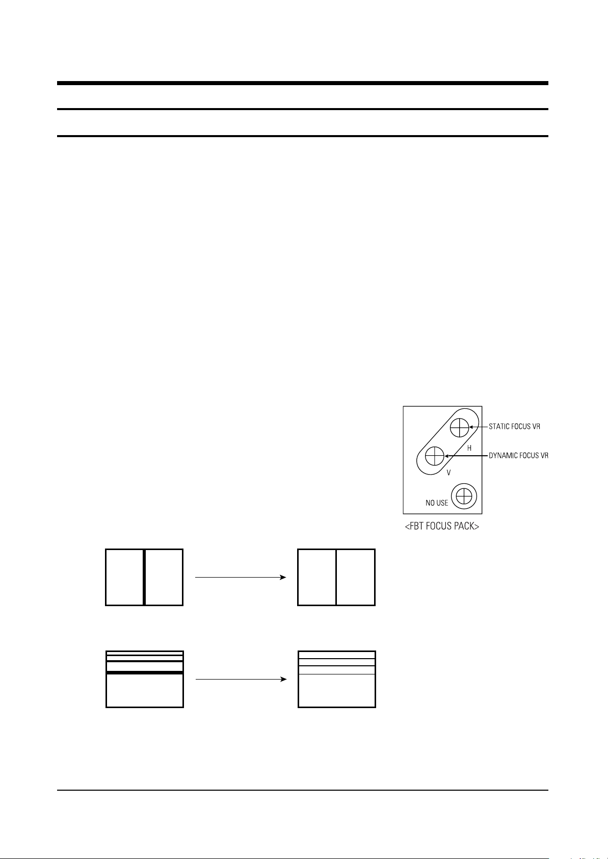
4-1-2 Focus Adjustment
K55A contains a dynamic focus circuit. When CRT PCB, FBT or CRT is replaced, be sure to adjust in the
following sequence:
Dynamic Focus Adjustment
1. Input a crosshatch pattern.
2. Select “Standard” from the menu,
3. Turn the Static Focus VR clockwise to set it to its maximum.
4. Turn the Dynamic Focus VR counterclockwise to set it to its
maximum.
5. Turn the Static Focus VR counterclockwise slowly for the clearest
center vertical line.
6. Turn the Dynamic Focus VR clockwise slowly for the clearest third line.
7. Check for the FOCUS of entire screen. If necessary, re-do adjustments 3~6.
After Adjustment
1
2
3
Page 14
Alignment and Adjustments
4-2 Samsung Electronics
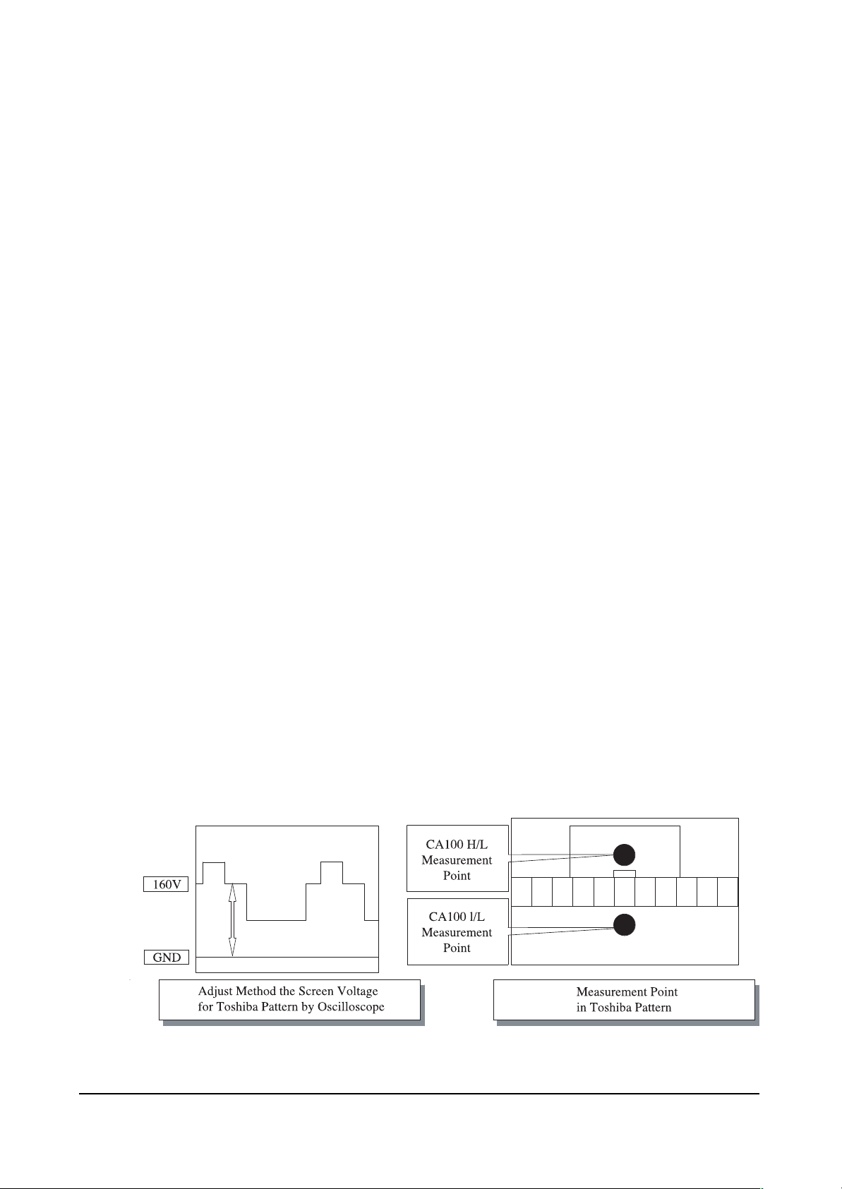
4-1-3 Screen Voltage Adjustment
1. Input a Toshiba pattern.
2. Use an oscilloscope to identify RK, BK, GK. And then adjust FBT Screen VR so that the voltage of
pedestal level doesn’t exceed 160V.
If a Toshiba pattern is not available, cancel the blue screen and input “No Signal” to AV IN so the voltage
of pedestal level doesn’t exceed 175V.
If an oscilloscope is not available, use a DC multi-meter in No Signal (black screen) to adjust RK, BK, GK
so that the highest voltage becomes 160Vp-p.
4-1-4 White Balance Adjustment
1. Warm up the TV set for at least 30 minutes.
2. Enter the Service Mode by pressing the remote control keys in the following sequence:
Power Off ➞ Display ➞ Menu ➞ Mute ➞ Power On
3. Initialize all set data.
4. Input a Toshiba pattern.
5. Using a probe(CA100), do the White Balance adjustments.
(1) Adjust Low-Light.
- Adjust Sub Brightness to set Y.
- Adjust B Cutoff to set y.
- Adjust R Cutoff to set x.
(2) Adjust High-Light.
- Adjust Sub Contrast to set Y.
- Adjust B Drive to set y.
- Adjust R Drive to set x.
(3) Check the value of Low-Light. If necessary, readjust Low-Light.
(4) Check the value of High-Light. If necessary, readjust High-Light.15
Page 15

Alignment and Adjustments
Samsung Electronics 4-3
4-1-5 When adjusting Screen Voltage and White Balance
1. Screen Voltage and White Balance are related each other. Make sure both adjustments are correct.
2. Adjust Screen Voltage before White Balance Adjustments. Make sure Screen Voltage is correct.
3. If White Balance has been readjusted, re-check Screen Voltage.
4. After adjustments are complete, check the following.
- If spots appear on the screen after pressing the Power On/Off key, readjust Screen Voltage.
- If flyback lines appear on the screen, readjust Screen Voltage.
Page 16
ASSIGNMENT
RESET Control jack during E2PROM latch UP(Function:Low)SERIAL H
E2PROM only SDA LINE
E2PROM only SDA LINE
Automation and after-sales service related BUS STOP(STOP : LOW)
CXA2165 /CXA2151Q/VSP940X/BA7654F/MSP34XX/TUNER Control jack
CXA2165 /CXA2151Q/VSP940X/BA7654F/MSP34XX/TUNER Control jack
Reset when MSP34XX IC(SOUND PROCESS IC)has an error(Active : LOW)
Reset when VSP940X IC(1-chip IC)has an error
Analog GND
TTX and USA Caption Input source line(1V p-p)
Main AFT Control jack(0 ~ 3.3V)
MICOM “H-SYNC” Input, POSITIVE Input(3.3V p-p)
MICOM “V-SYNC” Input, POSITIVE Input(3.3V p-p)
OPEN
TV/VIDEO switching control jack
Function : LOW
Remote Control Input Jack
STAND BY : Hight, OFF : LOW
TIME ON : H TIME OFF : L
DEGAUSSIGN COIL CONTROL:Based on standard specifications
H : IN1, L : IN2(BA7657F) PIN(#16) Control jack
Reset active : HIGH
Crystal oscillation input jack
Alignment and Adjustments
4-4 Samsung Electronics
4-2 MICOM PORT
PIN
1
2
3
4
5
6
7
8
9
10
11
12
13
14
15
16
17
18
19
20
21
22
23
24
25
26
27
28
29
30
33
34
35
FUNCTION
W-PORT
ROM SDA
ROM SCL
BUS-STOP
MAIN SDA
MAIN SCL
S-RESET
V-RESET
VDD 2.5V
GND
VDD3.3V
CVBS IN
VDD2.5V
GND
AFT
SC1-ID
SC2-ID
KEY-1
H-SYNC
V-SYNC
KEY-3
KEY-2
X-RAY
IR-IN
STD-LED
TIM-LED
RELAY
SW1
GND
VDD 3.3V
RESET
X-IN
X-OUT
FIRST STATE
HIGH
SERIAL H
SERIAL H
HIGH
SERIAL H
SERIAL H
HIGH
HIGH
HIGH
HIGH
IV p-p
HIGH
HIGH
POSITIVE
POSITIVE
HIGH
HIGH
HIGH
HIGH
LOW
HIGH
HIGH
LOW
RANGE
TV MODE
0 ~ 2V
16 : 9 MODE
4.5 ~ 7V
4 : 3 MODE
9.5 ~ 12V
AV MODE
16 : 9 MODE
0 ~ 2V
MEMU
0~0.1V
VOL-
0.1~0.7V
VOL+
07~13V
CH-
1.3~1.9V
CH+
0.9~2.4V
Page 17
Alignment and Adjustments
Samsung Electronics 4-5
ASSIGNMENT
OSD R-OUT Output jack (0.38V p-p), half tone : 0.9V p-p
OSD G-OUT Output jack (0.38V p-p), half tone : 0.9V p-p
OSD B-OUT Output jack (0.38V p-p), half tone : 0.9V p-p
OSD F/B-OUT Output jack (Clamped at STAND PULSE, Half Tone : LOW)
LOW : GNDHIGH : OPEN STATUS
Initially, these pins select an input source at LOW state
System (NTSC/PAL) MUST be separated
Active “LOW”
1080i control jack : 1080i (LOW), RF (Hight)
Magnetic field control
PIN
36
37
38
39
40
41
42
43
44
45
46
47
48
49
50
51
52
FUNCTION
GND
VDD 2.5V
OSD-R
OSD-G
OSD-B
CPRE
VDD 2.5V
GND
VDD 3.3V
PX, Y
PX, Y
SW3
SW2
S-MUTE
POWER
H,P-ID
TILT
FIRST STATE
HIGH
1.2V p-p
1.2V p-p
1.2V p-p
0.9V p-p
HIGH
HIGH
HIGH
HIGH
H
L
HIGH
F1
L
M
F0
M
L
fH
1.75KHz (480i/480P)
33.75KHz (1080i)
Page 18
Alignment and Adjustments
4-6 Samsung Electronics
4-3 Factory Adjustment
4-3-1 Factory Adjustment values
SERVICE
Deflection
480P Offset
1080i Offset
Video Adjust1
Video Adjust2
Video Adjust3
Option
YC Delay
EEPROM
Reset
4-3-2 EUROPE & CIS Factory Data
ITEMS
V-AMP
V-SHIFT
H-EW
H-SHIFT
V-LIN(Fix)
UP-LIN(Fix)
LOW-LIN(Fix)
V-SC(Fix)
H-PAR
UP-COR
LOW-COR
H-TRA
BOW
ANGLE
V-POSI(Fix)
50
2.5
29” CIS
SDI CRT
33
28
26
0
9
9
4
3
38
25
31
18
33
28
35 -> 40
45
2
32” CIS
SDI CRT
33
28
32
0
9
9
3
1
38
25
31
18
33
28
40
50
2.5
34” CIS
TOS CRT
26
24
17
26
9
9
2
3
51
35
36
42
31
30
40
37
1.8
29” EUR
SDI CRT
33
28
26
0
9
9
4
3
38
25
31
18
33
28
35 -> 40
37
1.5
32” EUR
PHI CRT
41
26
36
21
11
9
1
0
19
33
33
43
33
28
40
H/L : 285/285 29” CIS, EU W/B COORDINATE
L/L : 285/285
REMARK
Vertical AMP adj(Gain Control)
Vertical Position adj(DC bias adj)
Horizontal AMP adj(Gain Control)
Horizontal Position adj(DC bias adj)
Vertical Linearity adj(Top/Bottom adj)
Vertical Linearity adj(Top adj)
Vertical Linearity adj(Bottom adj)
Vertical S correction adj
Horizontal pin distortion adj
Horizontal pin distortion up adj
Horizontal pin distortion low adj
Horizontal Tapezium distortion adj
Vertical line slope adj(parabola)
Vertical Linearity adj(sawtooth)
V-Position adj as to CRT inch
DEFLECTION : PAL
Page 19

Alignment and Adjustments
Samsung Electronics 4-7
ITEMS
V-AMP
V-SHIFT
H-EW
H-SHIFT
V-LIN
UP-LIN
LOW-LIN
V-SC
H-PAR
UP-COR
LOW-COR
H-TRA
BOW
ANGLE
V-POSI
29” CIS
SDI CRT
-7
-4
5
30
-4
-1
3
0
8
7
3
7
-1
-1
0
32” CIS
SDI CRT
-7
-4
5
30
-4
-1
3
0
8
7
3
7
-1
-1
0
34” CIS
TOS CRT
-7
-4
5
30
-4
-1
3
0
8
7
3
7
-1
-1
0
29” EUR
SDI CRT
-7
-4
5
30
-4
-1
3
0
8
7
3
7
-1
-1
0
32” EUR
PHI CRT
0
-1
1
3
-4
-1
3
0
1
2
-1
0
0
0
0
REMARK
Vertical AMP adj(Gain Control)
Vertical Position adj(DC bias adj)
Horizontal AMP adj(Gain Control)
Horizontal Position adj(DC bias adj)
Vertical Linearity adj(Top/Bottom adj)
Vertical Linearity adj(Top adj)
Vertical Linearity adj(Bottom adj)
Vertical S correction adj
Horizontal pin distortion adj
Horizontal pin distortion up adj
Horizontal pin distortion low adj
Horizontal Tapezium distortion adj
Vertical line slope adj(parabola)
Vertical Linearity adj(sawtooth)
V-Position adj as to CRT inch
DEFLECTION : NTSC
Page 20

Alignment and Adjustments
4-8 Samsung Electronics
ITEMS
R-Cutoff
G-Cutoff(Fix)
B-Cutoff
Color on/off
CR offset
CB offset
R-Drive
G-Drive(Fix)
B-Drive
Sub-Bright
Sub-Contrast
Sub-Color(Fix)
Sub-TInt(Fix)
CTI-Level(Fix)
COL AXIS(Fix)
LTI-Level(Fix)
VSU(Fix)
Merody Volume(Fix)
29” CIS
SDI CRT
41
25
28
1
32
32
37
32
32
32
7
15
28
1
1
1
2
7
32” CIS
SDI CRT
41
25
28
1
32
32
37
32
32
32
7
15
28
1
1
1
2
7
34” CIS
TOS CRT
46
32
18
1
32
32
46
32
26
40
7
10
28
1
1
1
2
7
29” EUR
SDI CRT
41
32
28
1
32
32
37
32
32
32
7
15
28
1
1
1
2
7
32” EUR
PHI CRT
41
32
38
1
32
32
40
32
38
47
7
15
28
1
1
1
2
7
REMARK
R-cutoff control adj
G-cutoff control adj
B-cutoff control adj
initial : “0” -> 1
DC-offset canceling adjust
DC-offset canceling adjust
R-Drive control adj
G-Drive control adj
B-Drive control adj
Sub-Bright control
Sub-Contrast control
color gain control(PAL SETTING AGAIN)
HUE control
Chrominance Transient Improvement
color detection axis setting(NTSC/USA)
Luminance Transient Improvement
vertical osd position
Volume gain control
Video Adjust 1
Page 21
Alignment and Adjustments
Samsung Electronics 4-9
ITEMS
ABL Mode
Gamma
DPIC Level
DC Trans
ABL-TH
VM-Level
VM-Coring
VM-f0
VM-Limit
VM-Delay
SHP CD
SHP f0
SHP f1&p/o
AKB Time
Bandpass
Highpass
29” CIS
SDI CRT
3
2
3
3
14
1
2
2
2
3
1
0
8
13
17h
23h
32” CIS
SDI CRT
3
2
3
3
15
1
2
2
2
3
1
0
8
13
17h
23h
34” CIS
TOS CRT
3
2
3
3
14
1
2
2
2
3
1
0
8
13
17h
23h
29” EUR
SDI CRT
3
2
3
3
14
1
2
2
2
3
1
0
8
13
17h
23h
32” EUR
PHI CRT
3
2
3
3
14
1
2
2
2
3
1
0
8
13
17h
23h
REMARK
Rpicture/bright ABL gain control
RGB output correction control
Dynamic picture black expansion control
Y-System DC transmission ratio
Threshold voltage adj ABL-IN
VM-OUT Level control
VM-OUT coring control
VM-f0 control
VM-Limit level control
VM-OUT phase control(reference to R-OUT)
Sharpness gain control(color satuation)
Sharpness f0 control (3Mhz)
Sharpness gain control(PAL SETTING AGAIN)
AKB Bch reference pulse time control
VSP9407B Band pass filter
VSP9407B High pass filter
Video Adjust 2
ITEMS
H comp
V comp
PIN comp
AFC comp
sync phase
NR Value
29” CIS
SDI CRT
7
4
2
0
0
6
32” CIS
SDI CRT
8
5
2
0
0
6
34” CIS
TOS CRT
4
4
7
0
0
6
29” EUR
SDI CRT
7
4
7
0
0
6
32” EUR
PHI CRT
6
4
2
0
0
6
REMARK
H-EHT compensation setting(PAL SETTING AGAIN)
V-EHT compensation setting(PAL SETTING AGAIN)
PIN-EHT compensation setting(PAL SETTING AGAIN)
AFC-EHT compensation
WHEN USED 74HC123
PAL SETTING AGAIN
Video Adjust 3
Page 22

Alignment and Adjustments
4-10 Samsung Electronics
ITEMS
Language
SOUND
CRT
AV JACK
AUTO FM
PIP
TXT LANGUAGE
LNA
HIGH DEVIATION
AV BY CH KEY
DTV
VGA
AGC
WOOFER
SPEAKER
TTX TOP
HELP
TTX ON/OFF
TTX LIST PRIARITY
29” CIS
SDI CRT
CIS
V-DOLBY
4:3
SCART
ON
ON
ON
ON
OFF
OFF
OFF
OFF
OFF
OFF
NON
NON
NON
NON
NON
32” CIS
SDI CRT
CIS
V-DOLBY
WIDE
SCART
ON
ON
ON
ON
OFF
OFF
OFF
OFF
OFF
OFF
NON
NON
NON
NON
NON
34” CIS
TOS CRT
CIS
V-DOLBY
4:3
SCART
ON
ON
ON
OFF
OFF
OFF
OFF
OFF
OFF
NON
NON
NON
NON
NON
NON
29” EUR
SDI CRT
NON
V-DOLBY
WIDE
SCART
ON
ON
WESTERN
EUROPE
ON
OFF
OFF
OFF
OFF
OFF
OFF
DOME SPK
OFF
OFF
ON
NON
32” EUR
PHI CRT
NON
V-DOLBY
WIDE
SCART
ON
ON
WESTERN
EUROPE
ON
OFF
OFF
OFF
OFF
OFF
OFF
DOME SPK
OFF
OFF
ON
NON
REMARK
CIS/ARAB
V-DOLBY/A2-NICAM
SCART(CIS,EUROPE)/RCA(ASIA,AUSTRAILIA)
ON/OFF
ON/OFF(W/O PIP MODEL)
OPTION
ON/OFF(1 TUNER)
OFF/ON(INDIA)
OFF/ON
OFF/ON
OFF/OFF
OFF/ON
OFF/ON
EQ CURVE(DOME/NON DOME SPK)
OFF/ON
OFF/ON
OFF/ON
OFF/ON
Option Byte(CIS Model)
Page 23

Alignment and Adjustments
Samsung Electronics 4-11
ITEMS
P.YC(AV) DELAY
S.YC(AV) DELAY
N.YC(AV) DELAY
P.BG.YC DELAY
P.DK.YC DELAY
P.I.YC DELAY
P.M.YC DELAY
P.L.YC DELAY
S.BG.YC DELAY
S.DK.YC DELAY
S.I.YC DELAY
S.L.YC DELAY
N.M.YC DELAY
29” CIS
SDI CRT
1
-5
2
0
-2
-1
0
0
-6
-9
-9
0
0
32” CIS
SDI CRT
1
-5
2
0
-2
-1
0
0
-6
-9
-9
0
0
34” CIS
TOS CRT
1
-5
2
0
-2
-1
0
0
-6
-9
-9
0
0
29” EUR
SDI CRT
2
-5
4
4
2
1
0
0
-2
-7
-9
-5
0
32” EUR
PHI CRT
2
-5
4
4
2
1
0
0
-2
-7
-9
-5
0
REMARK
YC Delay
Page 24

Alignment and Adjustments
4-12 Samsung Electronics
Factory Control Name
UP-UCG(up corner semi control)
LO-UCG(low corner semi control)
LTI Mode
System
50 Hz Progressive Trapezium
60 Hz Progressive Trapezium
Dynamic Contrast
Dynamic Brightness
Dynamic Sharpness
Dynamic Color
Dynamic ColorTone
Dynamic Tint
Standard Contrast
Standard Brightness
Standard Sharpness
Standard Color
Standard ColorTone
Standard Tint
Movie Contrast
Movie Brightness
Movie Sharpness
Movie Color
Movie ColorTone
Movie Tint
PROGRESSIVE TTX V-POSITION
PROGRESSIVE TTX H-POSITION
Brightness(RGB/DVD)
Contrast(RGB/DVD)
U Saturation(RGB/DVD)
F-No
0
1
2
3
4
5
6
7
8
9
10
11
12
13
14
15
16
17
18
19
20
21
22
23
24
25
26
27
28
29
30
31
32
Range
0~3
0~3
0~3
0~3
0~255
0~255
0~100
0~100
0~100
0~100
0~100
0~100
0~100
0~100
0~100
0~100
0~100
0~100
0~100
0~100
0~100
0~100
0~100
0~100
0~255
0~255
0~100
0~100
0~100
0~100
0~255
0~255
0~255
29” CIS
SDI CRT
1
1
2
1
6
7
70
40
60
60
50
50
40
40
50
50
50
50
30
40
50
45
50
50
76
186
255
255
255
255
0
124
125
32” CIS
SDI CRT
0
0
2
1
5
7
70
40
60
70
50
50
50
40
50
60
50
50
35
40
50
55
50
50
78
187
255
255
255
255
0
124
125
34” CIS
TOS CRT
0
0
2
1
13
11
100
40
60
60
50
50
60
42
50
50
50
50
40
40
50
45
50
50
76
184
255
255
255
255
0
124
125
29” EUR
SDI CRT
0
0
1
2
6
7
70
50
40
60
50
50
50
45
40
50
50
50
40
45
40
45
50
50
76
186
255
255
255
255
0
124
125
32” EUR
PHI CRT
0
0
1
2
5
7
100
50
40
60
50
50
80
50
40
50
50
50
60
50
40
45
50
50
76
190
255
255
255
255
0
124
125
REMARK
EUROPE & CIS EEPROM Data
Page 25

Alignment and Adjustments
Samsung Electronics 4-13
Factory Control Name
V saturation(RGB/DVD)
9407 Y Gain
9407 U Gain
Luminance Delay(Fixed Value)
9407 V Gain
Start Value of Lum LUT(Main)-NR_ON
Noise Reduction(Main)-NR_ON
Start Value of Lum LUT(PIP)-NR_ON
Noise Reduction(PIP)-NR_ON
Vertical End of Clamping Pulse
SECAM Color Sensitivity(Main)
Vertical End of Clamping Pulse
SECAM Color Sensitivity(PIP)
Left Blanking
Right Blanking
S-ABL
P-ABL
Start Value of Lum LUT(Main)-NR_OFF
Noise Reduction(Main)-NR_OFF
Start Value of Lum LUT(PIP)-NR_OFF
Noise Reduction(PIP)-NR_OFF
Picture Limit Level
OSD LEVEL(LRGB2_LEV)
TTX LEVEL(LRGB2_LEV)
Left Blanking (480p)
Right Blanking (480p)
Left Blanking (1080i)
Right Blanking (1080i)
System (480p)
System (1080i)
CrCb Gain (480p)
CrCb Gain (1080i)
LTI Mode (480p)
F-No
33
34
35
36
37
38
39
40
41
42
43
44
45
46
47
48
49
50
51
52
53
54
55
56
57
58
59
60
61
62
63
64
65
Range
0~255
0~255
0~255
0~255
0~255
0~255
0~255
0~255
0~255
0~255
0~255
0~255
0~255
0~255
0~255
0~255
0~255
0~255
0~255
0~255
0~255
0~3
0~15
0~15
0~255
0~255
0~255
0~255
0~3
0~3
0~255
0~255
0~3
29” CIS
SDI CRT
248
93
83
8
82
255
102
255
102
28
28
28
28
147
153
0
48
255
255
255
255
3
7
0
0
0
0
0
0
0
0
0
0
32” CIS
SDI CRT
248
93
83
8
82
255
102
255
102
28
28
28
28
147
153
0
64
255
255
255
255
3
7
0
0
0
0
0
0
0
0
0
0
34” CIS
TOS CRT
248
93
83
8
82
255
102
255
102
28
28
28
28
147
153
0
48
255
255
255
255
3
10
0
0
0
0
0
0
0
0
0
0
29” EUR
SDI CRT
248
80
71
8
70
255
102
255
102
28
28
28
28
147
153
0
48
255
255
255
255
3
7
5
0
0
0
0
0
0
0
0
0
32” EUR
PHI CRT
248
80
71
8
70
255
102
255
102
28
28
28
28
147
153
0
48
255
255
255
255
3
7
5
0
0
0
0
0
0
0
0
0
REMARK
Page 26

Alignment and Adjustments
4-14 Samsung Electronics
Factory Control Name
LTI Mode (1080i)
TTX V Position
TTX H Position
16 PIP UPPER CORNER OFF SET
16 PIP LOWER CORNER OFF SET
4:3 Normal Parabola
F-No
66
67
68
69
70
71
Range
0~3
0~255
0~255
0~255
0~255
0~255
29” CIS
SDI CRT
0
37
186
2
1
0
32” CIS
SDI CRT
0
37
188
4
0
0
34” CIS
TOS CRT
0
37
185
3
3
0
29” EUR
SDI CRT
0
37
186
2
1
0
32” EUR
PHI CRT
0
38
190
4
0
0
REMARK
Page 27

Alignment and Adjustments
Samsung Electronics 4-15
4-3-3 AISA Factory Data
ITEMS
V-AMP
V-SHIFT
H- EW
H-SHIFT
V-LIN
UP-LIN
LOW-LIN
V-SC
H-PAR
UP-COR
LOW-COR
H-TRA
BOW
ANGLE
V-POSI
29” AISA
SDI CRT
35
22
40
22
7
9
4
1
33
18
27
24
33
31
40
32” Australia
LG CRT
24
27
34
21
9
9
3
1
20
32
35
32
32
30
40
29” Australia
SDI CRT
39
27
31
17
9
9
4
3
39
31
32
36
35
26
40
REMARK
Vertical AMP adj(Gain Control)
Vertical Position adj(DC bias adj)
Horizontal AMP adj(Gain Control)
Horizontal Position adj(DC bias adj)
Vertical Linearity adj(Top/Bottom adj)
Vertical Linearity adj(Top adj)
Vertical Linearity adj(Bottom adj)
Vertical S correction adj
Horizontal pin distortion adj
Horizontal pin distortion up adj
Horizontal pin distortion low adj
Horizontal Tapezium distortion adj
Vertical line slope adj(parabola)
Vertical Linearity adj(sawtooth)
V-Position adj as to CRT inch
DEFLECTION : PAL
Page 28

Alignment and Adjustments
4-16 Samsung Electronics
ITEMS
V-AMP
V-SHIFT
H- EW
H-SHIFT
V-LIN
UP-LIN
LOW-LIN
V-SC
H-PAR
UP-COR
LOW-COR
H-TRA
BOW
ANGLE
V-POSI
29” AISA
SDI CRT
-1
1
8
-9
0
0
0
0
0
0
0
-7
0
0
0
32” Australia
LG CRT
2
-3
4
-7
-4
-1
3
0
-4
3
-3
4
0
1
0
29” Australia
SDI CRT
-8
2
3
-9
0
-1
-3
2
1
-1
-1
3
2
0
0
REMARK
Vertical AMP adj( Gain Control)
Vertical Position adj (DC bias adj)
Horizontal AMP adj(Gain Control)
Horizontal Position adj (DC bias adj)
Vertical Linearity adj(TOP/Bottom adj)
Vertical Linearity adj(TOP adj)
Vertical Linearity adj(Bottom adj)
Vertical S correction adj
Horizontal pin distortion adj
Horizontal pin distortion up adj
Horizontal pin distortion low adj
Horizontal Trapezium distortion adj
Vertical line slope adj(parabola)
Vertical Linearity adj(sawtooth)
V-POSITION ADJ as to CRT INCH
480p Offset
ITEMS
V-AMP
V-SHIFT
H- EW
H-SHIFT
V-LIN
UP-LIN
LOW-LIN
V-SC
H-PAR
UP-COR
LOW-COR
H-TRA
BOW
ANGLE
V-POSI
29” AISA
SDI CRT
1
0
-2
10
-4
-1
2
0
1
4
-3
4
0
0
0
32” Australia
LG CRT
2
-2
0
8
-4
-1
3
0
0
1
-3
0
0
0
0
29” Australia
SDI CRT
1
-2
-1
9
-4
-1
2
0
2
2
-3
4
1
-1
0
REMARK
Vertical AMP adj( Gain Control)
Vertical Position adj (DC bias adj)
Horizontal AMP adj(Gain Control)
Horizontal Position adj (DC bias adj)
Vertical Linearity adj(TOP/Bottom adj)
Vertical Linearity adj(TOP adj)
Vertical Linearity adj(Bottom adj)
Vertical S correction adj
Horizontal pin distortion adj
Horizontal pin distortion up adj
Horizontal pin distortion low adj
Horizontal Trapezium distortion adj
Vertical line slope adj(parabola)
Vertical Linearity adj(sawtooth)
V-POSITION ADJ as to CRT INCH
DEFLECTION : NTSC
Page 29

Alignment and Adjustments
Samsung Electronics 4-17
ITEMS
V-AMP
V-SHIFT
H- EW
H-SHIFT
V-LIN
UP-LIN
LOW-LIN
V-SC
H-PAR
UP-COR
LOW-COR
H-TRA
BOW
ANGLE
V-POSI
29” AISA
SDI CRT
-14
2
6
4
0
0
0
0
0
0
0
0
0
0
0
32” Australia
LG CRT
-1
-2
-10
11
0
0
0
0
3
5
3
2
-1
1
0
29” Australia
SDI CRT
-4
-1
2
10
-1
0
-1
0
-1
0
1
-3
1
2
0
REMARK
Vertical AMP adj( Gain Control)
Vertical Position adj (DC bias adj)
Horizontal AMP adj(Gain Control)
Horizontal Position adj (DC bias adj)
Vertical Linearity adj(TOP/Bottom adj)
Vertical Linearity adj(TOP adj)
Vertical Linearity adj(Bottom adj)
Vertical S correction adj
Horizontal pin distortion adj
Horizontal pin distortion up adj
Horizontal pin distortion low adj
Horizontal Trapezium distortion adj
Vertical line slope adj(parabola)
Vertical Linearity adj(sawtooth)
V-POSITION ADJ as to CRT INCH
1080i Offset
Page 30

Alignment and Adjustments
4-18 Samsung Electronics
ITEMS
R-Cutoff
G-Cutoff
B-Cutoff
Color on/off
CR offset
CB offset
R-Drive
G-Drive
B-Drive
Sub-Bright
Sub-Contrast
Sub-Color
Sub-Tint
CTI-Level
COL AXIS
LTI-Level
VSU
Merody Volume
29” AISA
SDI CRT
41
32
28
1
32
32
37
32
32
32
7
15
28
1
1
1
2
4
32” Australia
LG CRT
31
32
43
1
32
32
37
32
43
33
7
15
28
1
1
1
2
4
29” Australia
SDI CRT
41
32
28
1
32
32
37
32
32
32
7
15
28
1
1
1
2
4
REMARK
R-cutoff control adj
G-cutoff control adj
B-cutoff control adj
Fixed :"0"--> 1
DC-offset canceling adjust
DC-offset canceling adjust
R-Drive control adj
G-Drive control adj
B-Drive control adj
Sub-Bright control
Sub-Contrast control
color gain control(PAL SETTING AGAIN)
HUE control
Chrominance Transient Improvement
color detection axis setting(NTSC/USA)
Luminance Transient Improvement
vertical osd position
Volume gain control
Video Adjust 1
Page 31

Alignment and Adjustments
Samsung Electronics 4-19
ITEMS
ABL Mode
Gamma
DPIC Level
DC Trans
ABL-TH
VM-Level
VM-Coring
VM-f0
VM-Limit
VM-Delay
SHP CD
SHP f0
SHP f1&p/o
AKB Time
Bandpass
Highpass
29” AISA
SDI CRT
3
2
3
3
14
1
2
2
2
3
1
0
8
13
17
23
32” Australia
LG CRT
3
2
3
3
15
1
2
2
2
3
1
0
8
13
17
23
29” Australia
SDI CRT
3
2
3
3
14
1
2
2
2
3
1
0
8
13
17
23
REMARK
picture/bright ABL gain control
RGB output correction control
Dynamic picture black expansion control
Y-System DC transmission ratio
Threshold voltage adj ABL-IN
VM-OUT Level control
VM-OUT coring control
VM-f0 control
VM-Limit level control
VM-OUT phase control(reference to R-OUT)
Sharpness gain control(color satuation)
Sharpness f0 control (3Mhz)
Sharpness gain control(PAL SETTING AGAIN)
AKB Bch reference pulse time control
VSP9407B Band pass filter
VSP9407B High pass filter
Video Adjust 2
ITEMS
H comp
V comp
PIN comp
AFC comp
sync phase
NR Value
sync phase(480p)
sync phase(1080i)
29” AISA
SDI CRT
7
4
2
0
0
6
1
0
32” Australia
LG CRT
6
4
2
0
0
6
1
0
29” Australia
SDI CRT
7
4
2
0
0
6
1
0
REMARK
H-EHT compensation setting(PAL SETTING AGAIN)
V-EHT compensation setting(PAL SETTING AGAIN)
PIN-EHT compensation setting(PAL SETTING AGAIN)
AFC-EHT compensation
WHEN USED 74HC123
PAL SETTING AGAIN
WHEN USED 74HC123
WHEN USED 74HC123
Video Adjust 3
Page 32

Alignment and Adjustments
4-20 Samsung Electronics
ITEMS
Sub-Bright
Sub-Contrast
Sub-Color
Sub-Tint
COL AXIS
LTI-Level
VM-Level
VM-Coring
VM-f0
VM-Limit
VM-Delay
SHP CD
SHP f0
SHP f1 & p/o
29” AISA
SDI CRT
19
7
15
28
1
2
1
2
2
2
3
1
0
8
32” Australia
LG CRT
38
7
15
28
1
2
1
2
2
2
3
1
0
8
29” Australia
SDI CRT
19
7
15
28
1
1
1
2
2
2
3
1
0
8
REMARK
DTV Adjust (480p/1080i)
ITEMS
Language
SOUND
CRT
AV JACK
AUTO FM
PIP
TXT LANGUAGE
LNA
HIGH DEVIATION
AV BY CH KEY
DTV
VGA
AGC
WOOFER
29” AISA
SDI CRT
Asia
V-DOLBY
4:3
RCA
ON
ON
ON
ON
OFF
OFF
ON
OFF
OFF
OFF
32” Australia
LG CRT
ASIA
V-DOLBY
WIDE
RCA
ON
ON
ON
ON
OFF
OFF
ON
OFF
OFF
OFF
29” Australia
SDI CRT
ASIA
V-DOLBY
4:3
RCA
ON
ON
ON
ON
OFF
OFF
ON
OFF
OFF
OFF
REMARK
CIS/ARAB
V-DOLBY/A2-NICAM
SCART(CIS,EUROPE)/RCA(ASIA,AUSTRAILIA)
ON/OFF
ON/OFF(W/O PIP MODEL)
RUSSIA/GREEK-TURKEY/ARABIC/FARSI/
ARAB-HEBREW/WEST EUROPE/EAST EUROPE
ON/OFF(1 TUNER)
OFF/ON(INDIA)
OFF/ON
OFF/ON
OFF/OFF
OFF/ON
OFF/ON (Z7PART : ON, OTHERS : OFF)
Option Byte(ASIA Model)
Page 33

Alignment and Adjustments
Samsung Electronics 4-21
ITEMS
P.YC(AV) DELAY
S.YC(AV) DELAY
N.YC(AV) DELAY
P.BG.YC DELAY
P.DK.YC DELAY
P.I.YC DELAY
P.M.YC DELAY
P.L.YC DELAY
S.BG.YC DELAY
S.DK.YC DELAY
S.I.YC DELAY
S.M.YC DELAY
S.L.YC DELAY
N.M.YC DELAY
29” AISA
SDI CRT
1
-5
2
0
-2
-1
0
0
-6
-9
-9
0
0
0
32” Australia
LG CRT
1
-5
2
0
-2
-1
0
0
-6
-9
-9
0
0
0
29” Australia
SDI CRT
1
-5
2
0
-2
-1
0
0
-6
-9
-9
0
0
0
REMARK
YC Delay
High Voltage(kV)
Beam Current(mA)
30.64kV
33.8kV
1.833mA
31.62kV
33.97kV
1.82mA
Lion-head(Dynamic mode)
Page 34

Alignment and Adjustments
4-22 Samsung Electronics
Factory Control Name
UP-UCG(up corner semi control)
LO-UCG(low corner semi control)
LTI Mode
System
50 Hz Progressive Trapezium
60 Hz Progressive Trapezium
Dynamic Contrast
Dynamic Brightness
Dynamic Sharpness
Dynamic Color
Dynamic ColorTone
Dynamic Tint
Standard Contrast
Standard Brightness
Standard Sharpness
Standard Color
Standard ColorTone
Standard Tint
Movie Contrast
Movie Brightness
Movie Sharpness
Movie Color
Movie ColorTone
Movie Tint
PROGRESSIVE TTX V-POSITION
PROGRESSIVE TTX H-POSITION
1080i 50Hz OSD V-POSITION
1080i 50Hz OSD H-POSITION
1080i 60Hz OSD V-POSITION
1080i 60Hz OSD H-POSITION
Brightness(RGB/DVD)
Contrast(RGB/DVD)
U Saturation(RGB/DVD)
F-No
0
1
2
3
4
5
6
7
8
9
10
11
12
13
14
15
16
17
18
19
20
21
22
23
24
25
26
27
28
29
30
31
32
Range
0~3
0~3
0~3
0~3
0~63
0~63
0~100
0~100
0~100
0~100
0~100
0~100
0~100
0~100
0~100
0~100
0~100
0~100
0~100
0~100
0~100
0~100
0~100
0~100
0~255
0~255
0~255
0~255
0~255
0~255
0~255
0~255
0~255
29” AISA
SDI CRT
1
1
2
1
6
7
90
50
50
60
50
50
70
50
50
50
50
50
50
50
50
45
50
50
76
186
32
255
32
184
0
124
125
32” Australia
LG CRT
0
0
2
1
7
7
100
50
50
60
50
50
80
50
40
50
50
50
60
50
40
50
50
50
78
187
32
255
32
184
0
124
125
29” Australia
SDI CRT
1
1
2
1
6
7
90
50
50
60
50
50
70
50
50
50
50
50
50
50
50
45
50
50
76
186
32
255
32
184
0
124
125
REMARK
ASIA EEPROM Data
Page 35

Alignment and Adjustments
Samsung Electronics 4-23
Factory Control Name
V saturation(RGB/DVD)
9407 Y Gain
9407 U Gain
Luminance Delay(FIX)
9407 V Gain
Start Value of Lum LUT(Main)-NR_ON
Noise Reduction(Main)-NR_ON
Start Value of Lum LUT(PIP)-NR_ON
Noise Reduction(PIP)-NR_ON
Vertical End of Clamping Pulse
SECAM Color Sensitivity(Main)
Vertical End of Clamping Pulse
SECAM Color Sensitivity(PIP)
Left Blanking
Right Blanking
S-ABL
P-ABL
Start Value of Lum LUT(Main)-NR_OFF
Noise Reduction(Main)-NR_OFF
Start Value of Lum LUT(PIP)-NR_OFF
Noise Reduction(PIP)-NR_OFF
Picture Limit Level
OSD LEVEL(LRGB2_LEV)
TTX LEVEL(LRGB2_LEV)
Left Blanking (480p)
Right Blanking (480p)
Left Blanking (1080i)
Right Blanking (1080i)
System (480p)
System (1080i)
CrCb Gain (480p)
CrCb Gain (1080i)
LTI Mode (480p)
F-No
33
34
35
36
37
38
39
40
41
42
43
44
45
46
47
48
49
50
51
52
53
54
55
56
57
58
59
60
61
62
63
64
65
Range
0~255
0~255
0~255
0~255
0~255
0~255
0~255
0~255
0~255
0~255
0~255
0~255
0~255
0~255
0~255
0~255
0~255
0~255
0~255
0~255
0~255
0~3
0~15
0~15
0~255
0~255
0~255
0~255
0~3
0~3
0~255
0~255
0~3
29” AISA
SDI CRT
248
93
83
8
82
255
102
255
102
28
28
28
28
147
153
0
48
255
255
255
255
3
12
5
195
165
167
125
1
1
119
119
1
32” Australia
LG CRT
248
93
83
8
82
255
102
255
102
28
28
28
28
147
153
0
48
255
255
255
255
3
12
5
195
165
167
125
1
1
119
119
1
29” Australia
SDI CRT
248
93
83
8
82
255
102
255
102
28
28
28
28
147
153
0
48
255
255
255
255
3
12
5
195
165
167
125
1
1
119
119
1
REMARK
Page 36

Alignment and Adjustments
4-24 Samsung Electronics
Factory Control Name
LTI Mode (1080i)
TTX V Position
TTX H Position
16PIP UPPER CORNER OFF SET
16 PIP LOWER CORNER OFF SET
4:3 Normal Parabola
F-No
66
67
68
69
70
71
Range
0~3
0~255
0~255
0~255
0~255
0~255
29” AISA
SDI CRT
1
38
186
4
1
0
32” Australia
LG CRT
1
38
188
0
0
0
29” Australia
SDI CRT
1
38
186
4
1
0
REMARK
Page 37

Alignment and Adjustments
Samsung Electronics 4-25
4-4 Screen Change(I2C Bus Geometric Adjustment)
0 V - Amp
1 V-Shift
2 H-EW
3 H-Shift
8 H-Parabola
9 Upper Coner
10 Low Coner
11
H- Trapezuim
4 V-Linearity
5 Upper Linearity
6 Low Linearity
7 V SC
12
13
14
Bow
Angle
V Position
Page 38

4-26 Samsung Electronics
MEMO
Page 39

Troubleshooting
Samsung Electronics 5-1
5. Troubleshooting
5-1 No Raster
Abnormal
Check VIN(DC)
TS801S PIN 13
Abnormal
Check
FA803S
GND SHORT
Abnormal
Check ST5V
Q804 "E"
Normal
Check ST5V
HC801"D809"
Abnormal
Normal
Normal
Check
FA801S
Check
B+(135V)
Check
ST-BY
MICOM
Abnormal
Check
NormalNormal
Normal
Check ON/OFF
IC903 ; 3.3V
F-BOX 5V, 9V
Check
Normal
Check
MICOM
Abnormal
Check9V:R829, IC803
5V:R827, FA802S
Check
HC401 J6920
Normal
Check
DZ801,DZ802,
DZ803,IC804
Check
Vin(dc)T801S
Abnormal
Check
FP801S
Check
CRT ASSY
R529
Normal
F-BOX I C
Check
Check
F-BOX HD,VD
Abnormal
Check HIC401
Q402
REPLACE
F-BOX
Check
H-BLK
V-BLK
Page 40

5-2 No Sound
Troubleshooting
5-2 Samsung Electronics
NO SOUND
Check
SPEAKER and WIRE
Check
TUNER B+ and SIF
Normal
Abnormal
Check the
signal of CN601
Abnormal
Check the
input signal
of IC601
Normal
Check
IC601 B+
Normal
Check the signals
of pins 47,44,are input
Normal
Check the signals
of pins 25,24 are input
Normal
Abnormal
Check the
input signal
of IC602 pins 7,11
Abnormal
CheckB+(BV) LINE
R815, IC805, FA802S
Normal
Check
IC602 B+
Normal
Replace IC602
Abnormal
Check FA803S
Repace IC601
Page 41

Troubleshooting
Samsung Electronics 5-3
5-3 No Power
Plug in the
Power Cord
Check Power LED
Abnomal
Check IC901 B+
(3.3VDD)
Abnomal
Check Q804
Abnomal
HC801S
FA801S
FA802S
Abnomal
Check
CN901, CN902
ST-BY : LED
Nomal
Nomal
Check/Replace IC901
Check I
Nomal
Check IC905
Check
TRANS(12V)
2
C
E2PROM
Abnomal
Check IC803,
IC802,R827,R829
Check the oscillation of
X-Tal of IC901 pins 34, 35
Check Reset of IC901 pin 33
Nomal
Check 135V Line
Nomal
Check F-BOX (5V)
Nomal
Check F-BOX
HD/VD
Abnomal
Abnomal
Check T444S
FBT B+
Nomal
Check IC801S,
DZ801,DZ802,
PC801S,IC804
Check
X901, IC904
Abnomal
Check the Horizontal
TR of HC401 "J6920"
Abnomal
Check F-BOX I
2
C
Check
HIC401,Q402
Nomal
Replace F-BOX
Check H-BLK,
V-BLK Line
Page 42

5-4 Samsung Electronics
5-4 Horizontal Lines Appear
Troubleshooting
Horizontal
lines appear
Nomal
Check / Replace
IC301
Nomal
Check F-BOX B+
VD+, VD-
Abnomal
Check IC802,IC803,
HC801,FA801S,FA803S
Check IC301 B+
(16V, -13.5V)
Abnomal
Check B+ line and
fusible resistance
Abnomal
Replace R424, R425
Page 43

6. Exploded View & Parts List
6-1 CS29Z6HPGX/BWT
Exploded View & Parts List
Samsung Electronics 6-1
No Code No Description;Specification Q’ty Remark S.N.A
1 AA96-00932D ASSY COVER P-FRONT;29Z6,CS29Z6HF,ABS HB0 1
1* AA64-02744D CABINET-FRONT;CS29Z6HF,ABS,HB0690M,G4309 1 S.N.A
1-1 AA64-70117B BADGE-BRAND;-,AL,-,-,L65,R2000,SILVER,SS 1 S.N.A
1-2 AA63-00571A COVER-A/V;29Z6,HIPS,HB,G4309,DGN-1189 1 S.N.A
1-3 AA63-00569B COVER-CONTROL;29Z6,HIPS,HB,G4309,DGN-118 1 S.N.A
1-4 6003-001268 SCREW-TAPTITE;TH,+,B,M4.0,L12.0,ZPC(YEL) 2 CA+CF S.N.A
1-5 6003-001268 SCREW-TAPTITE;TH,+,B,M4.0,L12.0,ZPC(YEL) 2 CC+CF S.N.A
1-6 AA64-02752A WINDOW-RMC;29Z6,PC,VO,VIOLET 1 S.N.A
1-7 AA64-02751B KNOB-POWER;29Z6,PC,VO,VIOLET,MASTER 1
1-8 AA61-60003J SPRING ETC-CS;-,SUS304,-,-,OD6,N7,OD6,-, 1 KNOPOW S.N.A
1-9 AA64-02753A INDICATOR LED;29Z6,ACRYL,HB,CLEAR 1 S.N.A
1-10 AA64-02750A DECORATION-POWER;29Z6,ABS,HB,GRAY,AL 1
1-11 6003-001019 SCREW-TAPTITE;RH,+,B,M4,L12,ZPC(BLK),SWR 2 DP+CF S.N.A
1-12 AA94-11730A ASSY PCB MISC-MASTER;Z6,Z7Z9,K55A,S57A,P 1
1-13 6003-000333 SCREW-TAPTITE;RH,+,2S,M3,L10,ZPC(YEL),SW 2 HP+PCB
1-14 AA64-02662A KNOB-CONTROL;Z7,ABS,HB,G3676,S104M+W971 1
1-15 6003-001019 SCREW-TAPTITE;RH,+,B,M4,L12,ZPC(BLK),SWR 2 KC+CC S.N.A
1-16 AA41-00651A PCB-CONTROL;CS29Z7HF,FR-1,1L,A,1.6T,330X 1 PCB S.N.A
1-17 AA96-00938B ASSY COVER P-COVER A/V;29Z6,CIS,HIPS HB, 1
1-18 6003-001268 SCREW-TAPTITE;TH,+,B,M4.0,L12.0,ZPC(YEL) 3 AV+CV S.N.A
1-19 AA91-00507A ASSY HOLDER SPK;-,-,8OHM/15W,-,ASSY HOLD 1
1-20 6006-001095 SCREW-ASS’Y TAPT;WP,BH,+,M4,L12,ZPC(YEL) 4 SPK+CF S.N.A
2 AA91-02173Q ASSY CPT;A68QCP891X004,29,+380MG,ITC,CT 1 S.N.A
2-1 AA63-60004K SPACER-GUM,CRT;-,NTR RUBBER,-,-,-,BLK,T2 4 S.N.A
2-2 AA65-00019A CLAMPER CORE-D,COIL;25-34,NYLON 66,V2,N 4 S.N.A
2-3 AA60-10050V SCREW-ASSY;-,SWRCH18A,M6,L30,HH,+,WC,-,Z 4 CRT+CF S.N.A
3 AA64-02745C CABINET BACK;29Z6,ABS,VO,G4309,SVM2012 1
3-1 AA60-10050T SCREW-TAPPING;-,SWRCH18A,M4,L20,RH,+,2S, 7 CB+CF S.N.A
3-2 AA96-20130H ASSY POWER CORD;-,CP2/NO(4.0R),H/S 500MM 1 S.N.A
You can search for the updated part code through ITSELF web site.
URL : http://itself.sec.samsung.co.kr
Page 44

Electrical Parts List
Samsung Electronics 7-1
7-1 CS29Z6HPGX/BWT
Level Loc. No. Code No. Description ; Specification Remark
7. Electrical Parts List
Level Loc. No. Code No. Description ; Specification Remark
ASSY CHASSIS
1 AA91-04827A ASSY CHASSIS;CS29Z6HPGX/BWT,K55A S.N.A
2 C-BLOC 6003-000333 SCREW-TAPTITE;RH,+,2S,M3,L10,ZPC(YEL),SW S.N.A
2 D-FOCU 6003-000333 SCREW-TAPTITE;RH,+,2S,M3,L10,ZPC(YEL),SW S.N.A
2 MP+HC 6003-000333 SCREW-TAPTITE;RH,+,2S,M3,L10,ZPC(YEL),SW S.N.A
2 PCB AA61-00706B HOLDER-COVER;ALL MODEL,NYLON-66 T1.0 V2, S.N.A
2 TBA+HC 6006-001095 SCREW-ASS’Y TAPT;WP,BH,+,M4,L12,ZPC(YEL) S.N.A
2 WP+HC 6003-000333 SCREW-TAPTITE;RH,+,2S,M3,L10,ZPC(YEL),SW S.N.A
2 AA94-08584P ASSY PCB MISC-CRT;29Z6,K55A,100HZ
3 C522 2201-002117 C-CERAMIC,DISC;4.7nF,20%,3kV,Y5U,TP,16x6
3 C523 2306-000272 C-FILM,MPPF;820nF,5%,400V,BK,29x25.5x18.
3 CNC01 3711-003974 CONNECTOR-HEADER;BOX,12P,1R,2.5mm,STRAIG
3 CNC01A AA39-00088A LEAD CONNECTOR-ASSY;HERCULES,UL1007/1185
3 CNC02 3711-003051 CONNECTOR-HEADER;BOX,8P,1R,2.5MM,STRAIGH
3 CNC02A AA39-00127A LEAD CONNECTOR-ASSY;,8P,400MM,35155-0800
3 GT501A AA39-00341A LEAD CONNECTOR;K55A(WT-32Z4HD),UL1015#18
3 GT503S AA39-20010B LEAD CONNECTOR-ASSY;,1P,500,YFH800-01,S,
3 IC501 AA96-50311L ASSY H/S;-,AMP,AA62-30175D ,TDA6111Q,HE S.N.A
3 IC502 AA96-50311L ASSY H/S;-,AMP,AA62-30175D ,TDA6111Q,HE S.N.A
3 IC503 AA96-50311L ASSY H/S;-,AMP,AA62-30175D ,TDA6111Q,HE S.N.A
4 1201-001131 IC-VIDEO AMP;6111,SIP,9P,-,SINGLE,-,PLAS
4 6003-000334 SCREW-TAPTITE;RH,+,2S,M3,L6,ZPC(YEL),SWR
4 AA62-30175D HEAT SINK-PS;-,SECC,T1.0,-,33X15X30 FT-2 S.N.A
3 IC504 BH99-00038E ASSY HEAT/SINK;TDA2030,AMP,HERCULES,BH62 S.N.A
4 CIS 0205-001027 OIL-SILICON;G746,-,- S.N.A
4 CIS 1201-000010 IC-OP AMP;2030,PENTAWATT,5P,-,SINGLE,-,C
4 CIS BH61-00004A SPRING ETC-TR;CDA,CDB,SUS304,-,-,-,-,-,T S.N.A
4 CIS BH62-00041A HEAT SINK-TR;PN17LT,A1050S,T1.0,50,23,-, S.N.A
3 QF09 AA96-00243M ASSY H/S;-,AMP,AA62-000450A,2SA1011,HERC S.N.A
4 0205-000129 GREASE-SILICON;SC102,JAPAN S.N.A
4 0502-000131 TR-POWER;2SA1011-D,PNP,1.2W,TO-220,-,60
4 6003-000335 SCREW-TAPTITE;RH,+,2S,M3,L8,ZPC(YEL),SWR S.N.A
4 AA62-00045A HEAT SINK-PS;-,-,T1.0,-,-,DREAM,-,-,-,-, S.N.A
3 QF10 AA96-00243L ASSY H/S;-,CRT,AA62-000450A,2SC2344,HERC S.N.A
4 0205-000129 GREASE-SILICON;SC102,JAPAN S.N.A
4 0502-000153 TR-POWER;2SC2344-D,NPN,1.2W,TO-220,-,60
4 6003-000335 SCREW-TAPTITE;RH,+,2S,M3,L8,ZPC(YEL),SWR S.N.A
4 AA62-00045A HEAT SINK-PS;-,-,T1.0,-,-,DREAM,-,-,-,-, S.N.A
3 SC01 3722-001503 JACK-PIN;1P,1PI,NI,RED,SCR-JACK
3 V999S 3704-001032 SOCKET-CRT;8P,29PI,35.5PI,AU30U
3 0202-000187 SOLDER-WIRE FLUX;-,RS60S,D1.2,63Sn/37Pb S.N.A
3 AA97-12040A ASSY AUTO-CRT;CS29Z6HP,K55A S.N.A
4 C501 2201-000193 C-CERAMIC,DISC;0.01NF,0.25PF,50V,C0G,TP,
4 C504 2301-000016 C-FILM,PEF;22nF,5%,100V,TP,7.2x4.5x9.0mm
4 C505 2301-000016 C-FILM,PEF;22nF,5%,100V,TP,7.2x4.5x9.0mm
4 C506 2301-000016 C-FILM,PEF;22nF,5%,100V,TP,7.2x4.5x9.0mm
4 C507 2301-000016 C-FILM,PEF;22nF,5%,100V,TP,7.2x4.5x9.0mm
4 C508 2301-001211 C-FILM,PPF;22nF,5%,400V,TP,20x7x14,7.5mm
4 C509 2301-000016 C-FILM,PEF;22nF,5%,100V,TP,7.2x4.5x9.0mm
4 C510 2201-000291 C-CERAMIC,DISC;1NF,10%,500V,Y5P,TP,7.5X3
4 C511 2301-001211 C-FILM,PPF;22nF,5%,400V,TP,20x7x14,7.5mm
4 C512 2301-001211 C-FILM,PPF;22nF,5%,400V,TP,20x7x14,7.5mm
4 C513 2201-000600 C-CERAMIC,DISC;0.56NF,10%,50V,Y5P,TP,5X3
4 C514 2201-000599 C-CERAMIC,DISC;0.56NF,10%,500V,Y5P,TP,5.
4 C515 2201-000599 C-CERAMIC,DISC;0.56NF,10%,500V,Y5P,TP,5.
4 C520 2401-000703 C-AL;2200uF,20%,25V,GP,-,12.5x25mm,
4 C526 2301-001211 C-FILM,PPF;22nF,5%,400V,TP,20x7x14,7.5mm
4 C528 2401-000832 C-AL;220uF,20%,25V,GP,TP,8x11.5,5
4 C531 2401-002264 C-AL;10uF,20%,350V,GP,TP,10x20mm,5m
4 C532 2401-001563 C-AL;47uF,20%,400V,GP,TP,16x25,7.5
4 C533 2305-000665 C-FILM,MPEF;100nF,5%,63V,TP,7.5x4.0x5.0m
4 C534 2401-000832 C-AL;220uF,20%,25V,GP,TP,8x11.5,5
4 C535 2401-000913 C-AL;22uF,20%,16V,GP,TP,5x11,5
4 CF01 2401-000360 C-AL;100uF,20%,50V,GP,TP,8x11.5,5
4 CF02 2201-000017 C-CERAMIC,DISC;1NF,10%,50V,Y5P,TP,5X3.5M
4 CF03 2201-000192 C-CERAMIC,DISC;0.01NF,0.25PF,500V,C0G,TP
4 CF04 2201-000516 C-CERAMIC,DISC;4.7NF,+100-0%,500V,Y5U,TP
4 CF05 2301-000261 C-FILM,PEF;4.7nF,5%,100V,TP,10.5x12.5x6.
4 CF06 2201-000192 C-CERAMIC,DISC;0.01NF,0.25PF,500V,C0G,TP
4 CF07 2201-000604 C-CERAMIC,DISC;0.056NF,+100-0%,500V,SL,T
4 CF71 2401-000832 C-AL;220uF,20%,25V,GP,TP,8x11.5,5
4 CF73 2401-000927 C-AL;22uF,20%,250V,GP,TP,13x20,5
4 CF74 2401-000025 C-AL;100uF,20%,16V,GP,TP,6.3x11,5
4 CF75 2401-000045 C-AL;10uF,20%,160V,GP,TP,10x16,5
4 D501 0401-000005 DIODE-SWITCHING;1N4148,100V,200mA,DO-35,
4 D502 0402-000546 DIODE-RECTIFIER;TVR10G,400V,1.0A,DO-41,T
4 D509 0402-000546 DIODE-RECTIFIER;TVR10G,400V,1.0A,DO-41,T
4 D510 0402-000546 DIODE-RECTIFIER;TVR10G,400V,1.0A,DO-41,T
4 D511 0402-000546 DIODE-RECTIFIER;TVR10G,400V,1.0A,DO-41,T
4 D512 0402-000546 DIODE-RECTIFIER;TVR10G,400V,1.0A,DO-41,T
4 D513 0402-000546 DIODE-RECTIFIER;TVR10G,400V,1.0A,DO-41,T
4 D514 0402-000546 DIODE-RECTIFIER;TVR10G,400V,1.0A,DO-41,T
4 DF01 0401-000005 DIODE-SWITCHING;1N4148,100V,200mA,DO-35,
4 DF02 0401-000005 DIODE-SWITCHING;1N4148,100V,200mA,DO-35,
4 DF05 0401-000005 DIODE-SWITCHING;1N4148,100V,200mA,DO-35,
4 DF06 0401-000005 DIODE-SWITCHING;1N4148,100V,200mA,DO-35,
4 DF07 0402-000546 DIODE-RECTIFIER;TVR10G,400V,1.0A,DO-41,T
4 DF08 0402-000546 DIODE-RECTIFIER;TVR10G,400V,1.0A,DO-41,T
4 DZ501 0403-000708 DIODE-ZENER;MTZJ13B,13V,12.55-13.21V,500
4 DZ502 0403-000708 DIODE-ZENER;MTZJ13B,13V,12.55-13.21V,500
4 DZ504 0403-000698 DIODE-ZENER;TZP12A,12V,11.4-12.6V,1W,DO4 DZ510 0403-000734 DIODE-ZENER;TZP15B,15V,14.7-16.5V,1W,DO4 DZF01 0403-001039 DIODE-ZENER;MA2560,56V,52-60V,1W,DO-41,T
4 DZF02 0403-001039 DIODE-ZENER;MA2560,56V,52-60V,1W,DO-41,T
4 DZF03 0403-000508 DIODE-ZENER;MTZJ5.6B,5.6V,5.45-5.73V,500
4 EL100 6042-000001 EYELET;ID2.2,OD2.7,L3.1,SN,BSS3-E/EH S.N.A
4 EL80 6042-000001 EYELET;ID2.2,OD2.7,L3.1,SN,BSS3-E/EH S.N.A
4 EL81 6042-000001 EYELET;ID2.2,OD2.7,L3.1,SN,BSS3-E/EH S.N.A
4 EL82 6042-000001 EYELET;ID2.2,OD2.7,L3.1,SN,BSS3-E/EH S.N.A
4 EL83 6042-000001 EYELET;ID2.2,OD2.7,L3.1,SN,BSS3-E/EH S.N.A
4 EL84 6042-000001 EYELET;ID2.2,OD2.7,L3.1,SN,BSS3-E/EH S.N.A
4 EL85 6042-000001 EYELET;ID2.2,OD2.7,L3.1,SN,BSS3-E/EH S.N.A
4 EL86 6042-000001 EYELET;ID2.2,OD2.7,L3.1,SN,BSS3-E/EH S.N.A
4 EL87 6042-000001 EYELET;ID2.2,OD2.7,L3.1,SN,BSS3-E/EH S.N.A
4 EL88 6042-000001 EYELET;ID2.2,OD2.7,L3.1,SN,BSS3-E/EH S.N.A
4 EL89 6042-000001 EYELET;ID2.2,OD2.7,L3.1,SN,BSS3-E/EH S.N.A
4 EL92 6042-000001 EYELET;ID2.2,OD2.7,L3.1,SN,BSS3-E/EH S.N.A
4 EL94 6042-000001 EYELET;ID2.2,OD2.7,L3.1,SN,BSS3-E/EH S.N.A
4 EL95 6042-000001 EYELET;ID2.2,OD2.7,L3.1,SN,BSS3-E/EH S.N.A
4 EL96 6042-000001 EYELET;ID2.2,OD2.7,L3.1,SN,BSS3-E/EH S.N.A
4 EL97 6042-000001 EYELET;ID2.2,OD2.7,L3.1,SN,BSS3-E/EH S.N.A
4 EL98 6042-000001 EYELET;ID2.2,OD2.7,L3.1,SN,BSS3-E/EH S.N.A
4 EL99 6042-000001 EYELET;ID2.2,OD2.7,L3.1,SN,BSS3-E/EH S.N.A
4 FN1 3711-002643 CONNECTOR-HEADER;BOX,4P,1R,2.5mm,STRAIGH
4 FV1 3711-002642 CONNECTOR-HEADER;BOX,3P,1R,2.5mm,STRAIGH
4 GT501 AA60-40014A PIN-GT,ASSY;AUTO S.N.A
4 GT502 AA60-40014A PIN-GT,ASSY;AUTO S.N.A
4 GT503 AA60-40014A PIN-GT,ASSY;AUTO S.N.A
4 GT504 AA60-40014A PIN-GT,ASSY;AUTO S.N.A
4 L502 2701-000178 INDUCTOR-AXIAL;33uH,10%,3x7mm
4 LF01 2901-000297 FILTER-EMI ON BOARD;-,3A,-,-,3.5x5,TP,4 LF02 2901-000297 FILTER-EMI ON BOARD;-,3A,-,-,3.5x5,TP,4 LF03 2701-000112 INDUCTOR-AXIAL;100uH,10%,3x7mm
You can search for the updated part code through ITSELF web site.
URL : http://itself.sec.samsung.co.kr
Page 45

4 LF04 2901-000297 FILTER-EMI ON BOARD;-,3A,-,-,3.5x5,TP,4 LF06 2901-000297 FILTER-EMI ON BOARD;-,3A,-,-,3.5x5,TP,4 LF08 2901-000297 FILTER-EMI ON BOARD;-,3A,-,-,3.5x5,TP,4 LF09 2901-000297 FILTER-EMI ON BOARD;-,3A,-,-,3.5x5,TP,4 LF11 2901-000297 FILTER-EMI ON BOARD;-,3A,-,-,3.5x5,TP,4 PCB AA41-00578D PCB-CRT;CT-29Z7HR,FR-1,1L,D,1.6T,330X245 S.N.A
4 Q501 0501-000283 TR-SMALL SIGNAL;KSA539,PNP,400mW,TO-92,T
4 Q502 0501-000283 TR-SMALL SIGNAL;KSA539,PNP,400mW,TO-92,T
4 Q503 0501-000283 TR-SMALL SIGNAL;KSA539,PNP,400mW,TO-92,T
4 Q504 0501-000283 TR-SMALL SIGNAL;KSA539,PNP,400mW,TO-92,T
4 QF02 0501-000389 TR-SMALL SIGNAL;KSC815,NPN,400mW,TO-92,T
4 QF03 0501-000389 TR-SMALL SIGNAL;KSC815,NPN,400mW,TO-92,T
4 QF04 0501-000283 TR-SMALL SIGNAL;KSA539,PNP,400mW,TO-92,T
4 QF05 0501-000389 TR-SMALL SIGNAL;KSC815,NPN,400mW,TO-92,T
4 R501 2001-000241 R-CARBON;1.5KOHM,5%,1/8W,AA,TP,1.8X3.2MM
4 R502 2001-000241 R-CARBON;1.5KOHM,5%,1/8W,AA,TP,1.8X3.2MM
4 R503 2001-001088 R-CARBON(S);1KOHM,5%,1/2W,AA,TP,2.4X6.4M
4 R504 2001-001045 R-CARBON(S);1.2KOHM,5%,1/2W,AA,TP,2.4X6.
4 R505 2001-001045 R-CARBON(S);1.2KOHM,5%,1/2W,AA,TP,2.4X6.
4 R506 2001-001194 R-CARBON(S);82KOHM,5%,1/2W,AA,TP,2.4X6.4
4 R507 2001-000472 R-CARBON;2.7KOHM,5%,1/8W,AA,TP,1.8X3.2MM
4 R508 2001-000995 R-CARBON;820OHM,5%,1/8W,AA,TP,1.8X3.2MM
4 R509 2008-001047 R-FUSIBLE(S);68ohm,5%,2W,AF,TP,3.9x10mm
4 R510 2001-001194 R-CARBON(S);82KOHM,5%,1/2W,AA,TP,2.4X6.4
4 R511 2001-001194 R-CARBON(S);82KOHM,5%,1/2W,AA,TP,2.4X6.4
4 R512 2004-001369 R-METAL(S);1.2Kohm,1%,1/2W,AA,TP,2.4x6.4
4 R513 2002-001017 R-COMPOSITION;1Kohm,10%,1/2W,AA,TP,3.7x9
4 R514 2002-001017 R-COMPOSITION;1Kohm,10%,1/2W,AA,TP,3.7x9
4 R515 2002-001017 R-COMPOSITION;1Kohm,10%,1/2W,AA,TP,3.7x9
4 R516 2001-001153 R-CARBON(S);47OHM,5%,1/2W,AA,TP,2.4X6.4M
4 R518 2001-001095 R-CARBON(S);2.2MOHM,5%,1/2W,AA,TP,2.4X6.
4 R519 2001-000356 R-CARBON;150KOHM,5%,1/8W,AA,TP,1.8X3.2MM
4 R520 2001-000563 R-CARBON;27KOHM,5%,1/8W,AA,TP,1.8X3.2MM
4 R522 2001-000290 R-CARBON;10KOHM,5%,1/8W,AA,TP,1.8X3.2MM
4 R523 2001-000890 R-CARBON;6.8KOHM,5%,1/8W,AA,TP,1.8X3.2MM
4 R525 2002-001006 R-COMPOSITION;4.7KOHM,15%,1/2W,AA,TP,3.7
4 R527 2001-000241 R-CARBON;1.5KOHM,5%,1/8W,AA,TP,1.8X3.2MM
4 R528 2003-000458 R-METAL OXIDE(S);100ohm,5%,2W,AF,TP,4x12
4 R530 2001-000273 R-CARBON;100KOHM,5%,1/8W,AA,TP,1.8X3.2MM
4 R531 2001-000539 R-CARBON;24KOHM,5%,1/8W,AA,TP,1.8X3.2MM
4 R540 2001-000429 R-CARBON;1KOHM,5%,1/8W,AA,TP,1.8X3.2MM
4 R541 2008-001053 R-FUSIBLE;22ohm,5%,1/2W,AF,TP,2.5x6.5mm
4 R554 2001-000429 R-CARBON;1KOHM,5%,1/8W,AA,TP,1.8X3.2MM
4 R555 2001-000429 R-CARBON;1KOHM,5%,1/8W,AA,TP,1.8X3.2MM
4 R556 2001-000429 R-CARBON;1KOHM,5%,1/8W,AA,TP,1.8X3.2MM
4 R560 2001-000052 R-CARBON(S);3.3KOHM,5%,1/2W,AA,TP,2.4X6.
4 R561 2001-001126 R-CARBON(S);300OHM,5%,1/2W,AA,TP,2.4X6.4
4 R562 2001-000273 R-CARBON;100KOHM,5%,1/8W,AA,TP,1.8X3.2MM
4 R563 2001-000273 R-CARBON;100KOHM,5%,1/8W,AA,TP,1.8X3.2MM
4 R564 2001-000290 R-CARBON;10KOHM,5%,1/8W,AA,TP,1.8X3.2MM
4 R565 2001-001071 R-CARBON(S);12KOHM,5%,1/2W,AA,TP,2.4X6.4
4 R566 2001-001040 R-CARBON(S);0.68OHM,5%,1/2W,AA,TP,2.4X6.
4 RF13 2008-001053 R-FUSIBLE;22ohm,5%,1/2W,AF,TP,2.5x6.5mm
4 RF14 2003-002276 R-METAL OXIDE(S);2.2KOHM,5%,2W,AG,TP,12X
4 RF15 2003-002276 R-METAL OXIDE(S);2.2KOHM,5%,2W,AG,TP,12X
4 RF16 2003-002276 R-METAL OXIDE(S);2.2KOHM,5%,2W,AG,TP,12X
4 RF17 2001-000019 R-CARBON(S);10OHM,5%,1/2W,AA,TP,2.4X6.4M
4 RF18 2001-001079 R-CARBON(S);15OHM,5%,1/2W,AA,TP,2.4X6.4M
4 RF19 2001-001079 R-CARBON(S);15OHM,5%,1/2W,AA,TP,2.4X6.4M
4 RF20 2001-000331 R-CARBON;12KOHM,5%,1/8W,AA,TP,1.8X3.2MM
4 RF21 2001-000258 R-CARBON;1.8KOHM,5%,1/8W,AA,TP,1.8X3.2MM
4 RF22 2001-000241 R-CARBON;1.5KOHM,5%,1/8W,AA,TP,1.8X3.2MM
4 RF23 2001-000554 R-CARBON;270OHM,5%,1/8W,AA,TP,1.8X3.2MM
4 RF24 2003-001018 R-METAL OXIDE(S);220ohm,5%,2W,AF,TP,3.9x
4 RF25 2001-000241 R-CARBON;1.5KOHM,5%,1/8W,AA,TP,1.8X3.2MM
4 RF26 2001-001179 R-CARBON(S);68KOHM,5%,1/2W,AA,TP,2.4X6.4
4 RF27 2001-001179 R-CARBON(S);68KOHM,5%,1/2W,AA,TP,2.4X6.4
4 RF28 2001-000241 R-CARBON;1.5KOHM,5%,1/8W,AA,TP,1.8X3.2MM
4 RF29 2001-001071 R-CARBON(S);12KOHM,5%,1/2W,AA,TP,2.4X6.4
4 RF30 2001-000221 R-CARBON;1.2KOHM,5%,1/8W,AA,TP,1.8X3.2MM
4 RF31 2001-000221 R-CARBON;1.2KOHM,5%,1/8W,AA,TP,1.8X3.2MM
4 RF32 2003-000746 R-METAL OXIDE(S);56ohm,5%,2W,AF,TP,4x12m
4 RF33 2001-001053 R-CARBON(S);1.5OHM,5%,1/2W,AA,TP,2.4X6.4
4 RF34 2001-001100 R-CARBON(S);2.7OHM,5%,1/2W,AA,TP,2.4X6.4
4 RF35 2003-000746 R-METAL OXIDE(S);56ohm,5%,2W,AF,TP,4x12m
4 RF36 2003-000652 R-METAL OXIDE(S);330ohm,5%,2W,AF,TP,4x12
2 AA96-00908E ASSY COVER P-TERMINAL BOARD;29Z6,CIS,HIP
3 AA64-02823A INLAY-T/BOARD;Z7,PS SHEET,T0.5,PAL S.N.A
3 AA65-00025A TERMINAL-BOARD,ANT;,HIPS V0,BLK S.N.A
2 AA94-11750A ASSY PCB MISC-A/V SIDE;29Z6,K55A,PAL
3 AV+CV 6003-001268 SCREW-TAPTITE;TH,+,B,M4.0,L12.0,ZPC(YEL) S.N.A
3 CN701 AA39-00317B LEAD CONNECTOR-ASSY;K55A/WT-32Z4HD,UL100
3 CN703 AA39-20069A LEAD CONNECTOR-ASSY;,5P,500,YBNH025-05,6
3 CN704 AA39-00070B LEAD CONNECTOR-ASSY;,4P,500MM,YBNH250-04
3 JA701 3722-001164 JACK-PIN;3P,3.4mm,SN,WH:YE:RE,#16-22
3 JK04 3722-000544 JACK-VHS;4P,11.5mm,AG,BLK,N
3 JKH701 3722-001061 JACK-PHONE;1P,3.6PI,AG,BLK,N
3 AA97-12697A ASSY AUTO-A/V SIDE;,K55A,PAL,29Z6 S.N.A
4 C701 2202-000121 C-CERAMIC,MLC-AXIAL;100pF,10%,50V,Y5P,TP
4 C702 2202-000121 C-CERAMIC,MLC-AXIAL;100pF,10%,50V,Y5P,TP
4 C707 2202-000231 C-CERAMIC,MLC-AXIAL;0.33NF,10%,50V,Y5P,T
4 C708 2202-000231 C-CERAMIC,MLC-AXIAL;0.33NF,10%,50V,Y5P,T
4 DZ701 0403-000563 DIODE-ZENER;MTZ9.1B,9.1V,8.57-9.01V,500m
4 L701 2701-000114 INDUCTOR-AXIAL;10uH,10%,2.5x3.4mm
4 L702 2701-000114 INDUCTOR-AXIAL;10uH,10%,2.5x3.4mm
4 L705 2701-000168 INDUCTOR-AXIAL;3.3uH,5%,2.5x3.4mm
4 L706 2701-000168 INDUCTOR-AXIAL;3.3uH,5%,2.5x3.4mm
4 L707 3301-000287 CORE-FERRITE BEAD;AA,3.5x1.0x6.0mm,1500,
4 L708 3301-000287 CORE-FERRITE BEAD;AA,3.5x1.0x6.0mm,1500,
4 PCB AA41-00620B PCB-A/V SIDE(Z7);CT-29Z7HR,FR-1,1L,B,1.6 S.N.A
4 R701 2001-000028 R-CARBON(S);100OHM,5%,1/2W,AA,TP,2.4X6.4
4 R702 2001-000028 R-CARBON(S);100OHM,5%,1/2W,AA,TP,2.4X6.4
3 AA96-00938B ASSY COVER P-COVER A/V;29Z6,CIS,HIPS HB,
4 AA63-60001R SPACER-FELT;-,FELT,-,-,-,-,T0.35,-,200X1 S.N.A
4 AA64-02667B INLAY-AV;Z7,PS SHEET,T0.3,DGN-K189,K55A S.N.A
4 AA63-00571A COVER-A/V;29Z6,HIPS,HB,G4309,DGN-1189 S.N.A
3 AA63-10002A BAND-TIE;NYLON66 V2,L100,NTR S.N.A
2 AA94-08584Q ASSY PCB MISC-CONTROL;29Z6,K55A,100HZ
3 CNY01 AA39-00100E LEAD CONNECTOR-ASSY;,4P,600MM,YBNH250-04
3 CPC+CC 6003-001268 SCREW-TAPTITE;TH,+,B,M4.0,L12.0,ZPC(YEL) S.N.A
3 SWY01 3404-000176 SWITCH-TACT;12V,50mA,120gf,6x6mm,SPST
3 SWY02 3404-000176 SWITCH-TACT;12V,50mA,120gf,6x6mm,SPST
3 SWY03 3404-000176 SWITCH-TACT;12V,50mA,120gf,6x6mm,SPST
3 SWY04 3404-000176 SWITCH-TACT;12V,50mA,120gf,6x6mm,SPST
3 SWY05 3404-000176 SWITCH-TACT;12V,50mA,120gf,6x6mm,SPST
3 SWY06 3404-000176 SWITCH-TACT;12V,50mA,120gf,6x6mm,SPST
3 0202-000187 SOLDER-WIRE FLUX;-,RS60S,D1.2,63Sn/37Pb S.N.A
3 AA97-12449A ASSY AUTO-CONTROL;29Z6,K55A,PAL S.N.A
4 DZY03 0403-000508 DIODE-ZENER;MTZJ5.6B,5.6V,5.45-5.73V,500
4 DZY04 0403-000508 DIODE-ZENER;MTZJ5.6B,5.6V,5.45-5.73V,500
4 LY01 2701-000114 INDUCTOR-AXIAL;10uH,10%,2.5x3.4mm
4 PCB AA41-00651A PCB-CONTROL;CS29Z7HF,FR-1,1L,A,1.6T,330X S.N.A
4 RY02 2001-000577 R-CARBON;2KOHM,5%,1/8W,AA,TP,1.8X3.2MM
4 RY03 2001-000007 R-CARBON;3KOHM,5%,1/8W,AA,TP,1.8X3.2MM
4 RY04 2001-000878 R-CARBON;6.2KOHM,5%,1/8W,AA,TP,1.8X3.2MM
4 RY05 2001-000009 R-CARBON;20KOHM,5%,1/8W,AA,TP,1.8X3.2MM
4 RY06 2001-000281 R-CARBON;100OHM,5%,1/8W,AA,TP,1.8X3.2MM
3 AA96-00935B ASSY COVER P-COVER CONTROL;29Z6,CIS,HIPS
4 KC+CC 6003-001019 SCREW-TAPTITE;RH,+,B,M4,L12,ZPC(BLK),SWR S.N.A
4 AA63-60001R SPACER-FELT;-,FELT,-,-,-,-,T0.35,-,200X1 S.N.A
4 AA64-02662A KNOB-CONTROL;Z7,ABS,HB,G3676,S104M+W971
4 AA63-00569B COVER-CONTROL;29Z6,HIPS,HB,G4309,DGN-118 S.N.A
2 AA96-20130H ASSY POWER CORD;-,CP2/NO(4.0R),H/S 500MM S.N.A
3 3811-000401 WIRE-PVC CU;BCWA,300V,ROLL,17/0.16mm,#22 S.N.A
3 AA39-10003B CBF POWER CORD;-,KJP-140,KLCE-2F,2.4m,HO
3 AA61-20284A HOLDER;P-CORD,PP,-,-,-,BLK,VO,KE-002 S.N.A
2 AA65-00011B CLAMPER CORE-WIRE;ALL MODEL,NYLON 66,V2, S.N.A
2 AA61-01190A HOLDER-CHASSIS;Z7,HIPS V0,G4309 S.N.A
2 AA94-07792A ASSY PCB MISC-DYNAMIC FOCUS;CT-29Z7HR,K5
3 LH01 AA26-90002C TRANS-DUMMY;-,-,-,-,-,-,-,-,-,-,-,-,EER2
3 LH02 AA27-40003L COIL HORIZ. WIDTH;-,1.0mH,DR14x20,2UEW0.
3 RH28 2008-001113 R-FUSIBLE(S);0.22ohm,10%,2W,AG,TP,3.9x12
3 WIRE3 AA39-20061C LEAD CONNECTOR-ASSY;,3P,200,YFH800-03,S,
3 0202-000187 SOLDER-WIRE FLUX;-,RS60S,D1.2,63Sn/37Pb S.N.A
3 AA97-07229L ASSY AUTO-DYNAMIC FOCUS;CT-29Z7HR,K55A S.N.A
4 EY01 6042-000002 EYELET;ID1.5,OD2,L3.1,SN,BSS3-E/EH S.N.A
4 EY02 6042-000002 EYELET;ID1.5,OD2,L3.1,SN,BSS3-E/EH S.N.A
4 EY03 6042-000002 EYELET;ID1.5,OD2,L3.1,SN,BSS3-E/EH S.N.A
4 EY04 6042-000002 EYELET;ID1.5,OD2,L3.1,SN,BSS3-E/EH S.N.A
4 EY05 6042-000002 EYELET;ID1.5,OD2,L3.1,SN,BSS3-E/EH S.N.A
4 EY06 6042-000002 EYELET;ID1.5,OD2,L3.1,SN,BSS3-E/EH S.N.A
4 EY07 6042-000002 EYELET;ID1.5,OD2,L3.1,SN,BSS3-E/EH S.N.A
Electrical Parts List
7-2 Samsung Electronics
Level Loc. No. Code No. Description ; Specification Remark Level Loc. No. Code No. Description ; Specification Remark
Page 46

Electrical Parts List
Samsung Electronics 7-3
Level Loc. No. Code No. Description ; Specification Remark Level Loc. No. Code No. Description ; Specification Remark
4 EY08 6042-000002 EYELET;ID1.5,OD2,L3.1,SN,BSS3-E/EH S.N.A
4 EY09 6042-000002 EYELET;ID1.5,OD2,L3.1,SN,BSS3-E/EH S.N.A
4 GTH01 AA60-40014A PIN-GT,ASSY;AUTO S.N.A
4 GTH02 AA60-40014A PIN-GT,ASSY;AUTO S.N.A
4 GTH03 AA60-40014A PIN-GT,ASSY;AUTO S.N.A
4 PCB AA41-00152C PCB-DOUBLE FOCUS;CW29A6VN8X/XEF,FR-1,1L, S.N.A
2 AA94-11187A ASSY PCB MAIN;CS29Z6HPJX/BWT,K55A
3 C-BLOC AA26-00069A TRANS FBT;FUJ-29C002C(S),DREAM3,4,-,-,-,
3 C806 2306-000112 C-FILM,MPPF;100nF,20%,250V,BK,-,15mm
3 C820 2401-003419 C-AL;2200uF,20%,50V,WT,TP,16X35.5mm
3 CABLE AA39-30007B CBF IF;-,T,150mm,1365#26
3 CN301 AA60-40012D PIN-GT,ASSY;T1.6,6-12.5-,NYLON66 S.N.A
3 CN502 3711-003051 CONNECTOR-HEADER;BOX,8P,1R,2.5MM,STRAIGH
3 CN702 3711-003974 CONNECTOR-HEADER;BOX,12P,1R,2.5mm,STRAIG
3 CN702A AA39-00114C LEAD CONNECTOR-ASSY;,12P,500MM,35155-120
3 D801S AA96-00276C ASSY H/S;-,BRIDGE ,AA62-00052A,GSIB660,K S.N.A
4 AA62-00052A HEAT SINK-PS;-,-,-,SILVER,HOLE 18.5mm, 2 S.N.A
4 AA60-30003A WASHER;T1.5,SBHG-1 S.N.A
4 6003-000335 SCREW-TAPTITE;RH,+,2S,M3,L8,ZPC(YEL),SWR S.N.A
4 0402-001399 DIODE-BRIDGE;GSIB660,600V,6A,SIP-4,BK
4 0205-000129 GREASE-SILICON;SC102,JAPAN S.N.A
3 GT804S AA39-20010C LEAD CONNECTOR-ASSY;,1P,600,YFH800-01,S,
3 HC401 BP96-00159A ASSY HEAT SINK P;H/S,SCREW,FJL6920,FMP-3 S.N.A
4 CIS AA60-30001A WASHER-PLATE;M3,ID3.5,15X8.5,T1.0,SBHG S.N.A
4 CIS 0205-001027 OIL-SILICON;G746,-,- S.N.A
4 CIS BP62-00015A HEAT SINK-PS;WT-36Z4HR,A1050S,T2.0,86,80 S.N.A
4 CIS BH73-00028B SILICON/RUBBER-HS;TV ALL,SILICON,26*30*T S.N.A
4 CIS 6003-000333 SCREW-TAPTITE;RH,+,2S,M3,L10,ZPC(YEL),SW S.N.A
4 CIS 0502-001230 TR-POWER;FJL6920YDTU,N,200000MW,TO-264 F
4 CIS 0402-001296 DIODE-RECTIFIER;FMP-3FU,1.5KV,5A,TO-3PF,
3 HC801 AA96-00475A ASSY H/S;-,REGULATOR,AA62-00066B,FML-G12 S.N.A
4 AA62-00066B HEAT SINK;D2,D3,AL ,T1.0,89,70,-,AA62-00 S.N.A
4 6003-000334 SCREW-TAPTITE;RH,+,2S,M3,L6,ZPC(YEL),SWR
4 1203-001006 IC-VOLTAGE REGULATOR;78R05,TO-220F,4P,-,
4 0402-001230 DIODE-RECTIFIER;FMG-G2CS,1000V,3A,TO-220
4 0402-000233 DIODE-RECTIFIER;FML-G12S,200V,5A,-,4 0205-000129 GREASE-SILICON;SC102,JAPAN S.N.A
3 IC301 AA96-50381A ASSY H/S;-,-,AA62-30180B,LA7845,- S.N.A
4 0205-000129 GREASE-SILICON;SC102,JAPAN S.N.A
4 1204-000517 IC-VERTICAL DEF.;LA7845,SIP,7P,-,PLASTIC
4 6003-000333 SCREW-TAPTITE;RH,+,2S,M3,L10,ZPC(YEL),SW S.N.A
4 AA62-30180B HEAT SINK-ES;-,A6063 EXTR.,2,WHT,70MM,-, S.N.A
3 IC602 AA96-50369D ASSY H/S;-,SOUND,AA62-30181F,TDA7269,HER S.N.A
4 0205-000129 GREASE-SILICON;SC102,JAPAN S.N.A
4 1201-001385 IC-POWER AMP;7269A,ZIP,11,19.6,DUAL,13,P
4 6003-000333 SCREW-TAPTITE;RH,+,2S,M3,L10,ZPC(YEL),SW S.N.A
4 AA62-30181F HEAT SINK-ES;-,AL6063 EXTR.,2,WHT,50MM,- S.N.A
3 IC801S AA96-50371H ASSY H/S;-,SMPS,AA62-30181H,5Q1565RF,HER S.N.A
4 AA61-11028A BRACKET;-,SECC,T1.0,-,-,-,- S.N.A
4 AA62-30181H HEAT SINK-ES;-,AL6063 EXTR.,2,WHT,50MM,- S.N.A
4 6003-000333 SCREW-TAPTITE;RH,+,2S,M3,L10,ZPC(YEL),SW S.N.A
4 1203-002512 IC-PWM CONTROLLER;KA5Q1565RF-YDTU,TO-3PF
4 0205-000129 GREASE-SILICON;SC102,JAPAN S.N.A
3 IC805 AA96-00243K ASSY H/S;-,REGULATOR,AA62-000450A,KA78R0 S.N.A
4 0205-000129 GREASE-SILICON;SC102,JAPAN S.N.A
4 6003-000335 SCREW-TAPTITE;RH,+,2S,M3,L8,ZPC(YEL),SWR S.N.A
4 AA62-00045A HEAT SINK-PS;-,-,T1.0,-,-,DREAM,-,-,-,-, S.N.A
4 1203-001006 IC-VOLTAGE REGULATOR;78R05,TO-220F,4P,-,
3 IC901 AA97-13892A ASSY MICOM;,K55A,SDA555X,SIM-832M4,02122
4 AA09-00041A IC MICOM;,SDA555X-OTP,3.3V,-,128K,SDIP,- S.N.A
3 JA701 3722-001884 JACK-SCART;42P,-,SNPB,BLK,3 JA702 3722-001767 JACK-PIN;2P(9P),-,NI,WHI/RED,3 LR402S AA27-10004F COIL CHOKE;-,56uH,K,-,2.5A,BK,-,DR12x15,
3 LR403S AA27-00070A COIL LINEARITY;-,7uH,YL81 DR1518,11mm,17
3 LR404S AA27-40001S COIL HORIZ. WIDTH;-,110uH,SB-5S8202.6,PI
3 Q402 0505-001116 FET-SILICON;BUZ73A,N,200V,22A,0.6ohm,40W
3 Q804 BH99-00007S ASSY HEAT/SINK;KSC2073,MICOM,HERCULES,BH S.N.A
4 CIS 0205-001027 OIL-SILICON;G746,-,- S.N.A
4 CIS 0502-001007 TR-POWER;KSC2073-H2,NPN,25W,TO-220,ST,6
4 CIS BH61-00004A SPRING ETC-TR;CDA,CDB,SUS304,-,-,-,-,-,T S.N.A
4 CIS BH62-00007A HEAT SINK-TR;-,T1.0,L20*H30,CDA S.N.A
3 RL801S 3501-001053 RELAY-POWER;5Vdc,530mW,10A,1FormA,15mS,5
3 T401 AA26-50001S TRANS-HORIZ.DRIVE;-,-,-,6.0mH,-,-,44uH,3 T444S AA26-00170A TRANS FBT;FUJ-29H002F,29F,1.95MH,FERRIT
3 T801S AA26-00178A TRANS SWITCHING;EER5345,K55A,PAL,CIS,160
3 TU02S AA40-00084A TUNER;TCPS3000PC16B(S),PAL ,181CH,38.9MH
3 X601 2801-004020 CRYSTAL-UNIT;18.432MHz,30ppm,28-AAM,12pF
3 AA95-03091A ASSY SUB-PCB,FEATURE BOX;,K55A, ,PAL
4 BR01 AA61-10068A BRACKET-PCB;M2160,SPTE,T0.3,-,-,-,- S.N.A
4 BR02 AA61-10068A BRACKET-PCB;M2160,SPTE,T0.3,-,-,-,- S.N.A
4 CN01 3711-003495 CONNECTOR-HEADER;NOWALL,34P,2R,2.54MM,AN
4 CN02 3711-003495 CONNECTOR-HEADER;NOWALL,34P,2R,2.54MM,AN
4 CN03 3711-003601 CONNECTOR-HEADER;BOX,12P,1R,2.5mm,ANGLE,
4 DC41 2309-000138 C-FILM,PE-PPF;100nF,5%,50V,TP,20x16x8.5,
4 DC51 2301-000224 C-FILM,PEF;22nF,5%,50V,TP,7.4x3.9x13mm,5
4 DX01 2802-001177 RESONATOR-CERAMIC;2.696MHZ,0.4%,BK,10X4.
4 EC48 2401-002463 C-AL;470uF,20%,16V,GP,TP,8x11.5,5
4 EC49 2401-002463 C-AL;470uF,20%,16V,GP,TP,8x11.5,5
4 EX01 2801-004019 CRYSTAL-UNIT;20.25MHz,30ppm,28-AAM,13pF,
4 IC06 1203-002000 IC-VOL. DETECTOR;7027,TO-92,3P,-,PLASTIC
4 AA97-12148A ASSY SMD;,K55A PAL S.N.A
5 DC01 2203-000440 C-CERAMIC,CHIP;1nF,10%,50V,X7R,TP,1608,5 DC02 2203-000440 C-CERAMIC,CHIP;1nF,10%,50V,X7R,TP,1608,5 DC03 2203-000181 C-CERAMIC,CHIP;100nF,+80-20%,25V,Y5V,TP,
5 DC04 2402-001042 C-AL,SMD;100uF,20%,16V,GP,TP,6.6x6.6x5.4
5 DC05 2203-000181 C-CERAMIC,CHIP;100nF,+80-20%,25V,Y5V,TP,
5 DC06 2402-000173 C-AL,SMD;4.7uF,20%,35V,GP,TP,4.3x4.3x5.
5 DC07 2203-000491 C-CERAMIC,CHIP;2.2nF,10%,50V,X7R,TP,1608
5 DC08 2203-002494 C-CERAMIC,CHIP;470nF,10%,16V,X7R,TP,2012
5 DC09 2402-000170 C-AL,SMD;1uF,20%,50V,GP,TP,4.3x4.3x5.4,
5 DC10 2203-000181 C-CERAMIC,CHIP;100nF,+80-20%,25V,Y5V,TP,
5 DC11 2203-000181 C-CERAMIC,CHIP;100nF,+80-20%,25V,Y5V,TP,
5 DC12 2402-001042 C-AL,SMD;100uF,20%,16V,GP,TP,6.6x6.6x5.4
5 DC13 2402-001042 C-AL,SMD;100uF,20%,16V,GP,TP,6.6x6.6x5.4
5 DC14 2203-000181 C-CERAMIC,CHIP;100nF,+80-20%,25V,Y5V,TP,
5 DC15 2203-000181 C-CERAMIC,CHIP;100nF,+80-20%,25V,Y5V,TP,
5 DC16 2203-000181 C-CERAMIC,CHIP;100nF,+80-20%,25V,Y5V,TP,
5 DC17 2203-000181 C-CERAMIC,CHIP;100nF,+80-20%,25V,Y5V,TP,
5 DC18 2203-000181 C-CERAMIC,CHIP;100nF,+80-20%,25V,Y5V,TP,
5 DC19 2203-000181 C-CERAMIC,CHIP;100nF,+80-20%,25V,Y5V,TP,
5 DC20 2203-002494 C-CERAMIC,CHIP;470nF,10%,16V,X7R,TP,2012
5 DC21 2203-000181 C-CERAMIC,CHIP;100nF,+80-20%,25V,Y5V,TP,
5 DC22 2203-002494 C-CERAMIC,CHIP;470nF,10%,16V,X7R,TP,2012
5 DC23 2402-000173 C-AL,SMD;4.7uF,20%,35V,GP,TP,4.3x4.3x5.
5 DC24 2402-001042 C-AL,SMD;100uF,20%,16V,GP,TP,6.6x6.6x5.4
5 DC25 2203-000181 C-CERAMIC,CHIP;100nF,+80-20%,25V,Y5V,TP,
5 DC26 2203-000181 C-CERAMIC,CHIP;100nF,+80-20%,25V,Y5V,TP,
5 DC27 2203-000181 C-CERAMIC,CHIP;100nF,+80-20%,25V,Y5V,TP,
5 DC28 2203-000181 C-CERAMIC,CHIP;100nF,+80-20%,25V,Y5V,TP,
5 DC29 2203-000181 C-CERAMIC,CHIP;100nF,+80-20%,25V,Y5V,TP,
5 DC30 2402-001042 C-AL,SMD;100uF,20%,16V,GP,TP,6.6x6.6x5.4
5 DC31 2203-002494 C-CERAMIC,CHIP;470nF,10%,16V,X7R,TP,2012
5 DC32 2203-000575 C-CERAMIC,CHIP;220NF,10%,25V,X7R,TP,2012
5 DC33 2203-002494 C-CERAMIC,CHIP;470nF,10%,16V,X7R,TP,2012
5 DC34 2203-000896 C-CERAMIC,CHIP;4.7nF,10%,50V,X7R,TP,1608
5 DC35 2203-000975 C-CERAMIC,CHIP;47nF,10%,25V,X7R,TP,1608,
5 DC36 2203-000257 C-CERAMIC,CHIP;10nF,10%,50V,X7R,TP,1608
5 DC37 2203-000181 C-CERAMIC,CHIP;100nF,+80-20%,25V,Y5V,TP,
5 DC38 2203-000181 C-CERAMIC,CHIP;100nF,+80-20%,25V,Y5V,TP,
5 DC39 2402-001049 C-AL,CHIP;10uF,20%,16V,GP,TP,3.3x3.3x5.4
5 DC40 2203-000440 C-CERAMIC,CHIP;1nF,10%,50V,X7R,TP,1608,5 DC43 2402-001042 C-AL,SMD;100uF,20%,16V,GP,TP,6.6x6.6x5.4
5 DC44 2203-000181 C-CERAMIC,CHIP;100nF,+80-20%,25V,Y5V,TP,
5 DC45 2203-000575 C-CERAMIC,CHIP;220NF,10%,25V,X7R,TP,2012
5 DC49 2402-000179 C-AL,SMD;47uF,20%,16V,GP,TP,6.6x6.6x5.4
5 DC50 2402-001049 C-AL,CHIP;10uF,20%,16V,GP,TP,3.3x3.3x5.4
5 DC52 2402-001049 C-AL,CHIP;10uF,20%,16V,GP,TP,3.3x3.3x5.4
5 DD01 0401-000133 DIODE-SWITCHING;RLS4148,100V,200MA,SOD-8
5 DD02 0401-000133 DIODE-SWITCHING;RLS4148,100V,200MA,SOD-8
5 DD03 0403-001117 DIODE-ZENER;RLZ12B,5%,500mW,LL-34,TP
5 DD04 0403-001117 DIODE-ZENER;RLZ12B,5%,500mW,LL-34,TP
5 DD05 0403-001117 DIODE-ZENER;RLZ12B,5%,500mW,LL-34,TP
5 DD06 0403-001117 DIODE-ZENER;RLZ12B,5%,500mW,LL-34,TP
5 DD07 0403-001117 DIODE-ZENER;RLZ12B,5%,500mW,LL-34,TP
5 DD08 0401-000133 DIODE-SWITCHING;RLS4148,100V,200MA,SOD-8
5 DD09 0401-000133 DIODE-SWITCHING;RLS4148,100V,200MA,SOD-8
5 DD10 0401-000133 DIODE-SWITCHING;RLS4148,100V,200MA,SOD-8
5 DD11 0403-000746 DIODE-ZENER;RLZ3.9B,3.89-4.16V,500MW,LL5 DD13 0401-000133 DIODE-SWITCHING;RLS4148,100V,200MA,SOD-8
5 DD14 0401-000133 DIODE-SWITCHING;RLS4148,100V,200MA,SOD-8
5 DD15 0401-000133 DIODE-SWITCHING;RLS4148,100V,200MA,SOD-8
5 DD16 0401-000133 DIODE-SWITCHING;RLS4148,100V,200MA,SOD-8
5 DD17 0401-000133 DIODE-SWITCHING;RLS4148,100V,200MA,SOD-8
5 DD18 0401-000133 DIODE-SWITCHING;RLS4148,100V,200MA,SOD-8
Page 47

5 DD19 0401-000133 DIODE-SWITCHING;RLS4148,100V,200MA,SOD-8
5 DD20 0403-000620 DIODE-ZENER;RLZ5.6B,5.6,500mW,LL-34,TP
5 DL01 2703-000398 INDUCTOR-SMD;10uH,10%,3.2x2.5x2.2mm
5 DL02 2703-000398 INDUCTOR-SMD;10uH,10%,3.2x2.5x2.2mm
5 DL03 2703-001070 INDUCTOR-SMD;100uH,10%,4.5x3.2x3.2mm
5 DQ01 0501-000344 TR-SMALL SIGNAL;KSC1623-G,NPN,200mW,SOT5 DQ02 0501-000280 TR-SMALL SIGNAL;KSA1182,PNP,150mW,SOT-23
5 DQ03 0501-000280 TR-SMALL SIGNAL;KSA1182,PNP,150mW,SOT-23
5 DQ04 0501-000280 TR-SMALL SIGNAL;KSA1182,PNP,150mW,SOT-23
5 DQ05 0501-000280 TR-SMALL SIGNAL;KSA1182,PNP,150mW,SOT-23
5 DQ06 0501-000344 TR-SMALL SIGNAL;KSC1623-G,NPN,200mW,SOT5 DQ07 0501-000344 TR-SMALL SIGNAL;KSC1623-G,NPN,200mW,SOT5 DQ08 0501-000344 TR-SMALL SIGNAL;KSC1623-G,NPN,200mW,SOT5 DQ09 0501-000727 TR-SMALL SIGNAL;BC848C,NPN,310mW,SOT-23,
5 DQ10 0501-000280 TR-SMALL SIGNAL;KSA1182,PNP,150mW,SOT-23
5 DQ11 0501-000344 TR-SMALL SIGNAL;KSC1623-G,NPN,200mW,SOT5 DR02 2007-000074 R-CHIP;100ohm,5%,1/16W,DA,TP,1608
5 DR03 2007-000074 R-CHIP;100ohm,5%,1/16W,DA,TP,1608
5 DR04 2007-000074 R-CHIP;100ohm,5%,1/16W,DA,TP,1608
5 DR05 2007-000074 R-CHIP;100ohm,5%,1/16W,DA,TP,1608
5 DR06 2007-000074 R-CHIP;100ohm,5%,1/16W,DA,TP,1608
5 DR07 2007-000070 R-CHIP;0ohm,5%,1/16W,DA,TP,1608
5 DR08 2007-000691 R-CHIP;3.3Mohm,5%,1/16W,DA,TP,1608
5 DR09 2007-000074 R-CHIP;100ohm,5%,1/16W,DA,TP,1608
5 DR10 2007-000074 R-CHIP;100ohm,5%,1/16W,DA,TP,1608
5 DR11 2007-000074 R-CHIP;100ohm,5%,1/16W,DA,TP,1608
5 DR13 2007-000086 R-CHIP;5.6Kohm,5%,1/16W,DA,TP,1608
5 DR14 2007-000086 R-CHIP;5.6Kohm,5%,1/16W,DA,TP,1608
5 DR15 2007-000869 R-CHIP;4.7Kohm,1%,1/16W,DA,TP,1608
5 DR16 2007-000074 R-CHIP;100ohm,5%,1/16W,DA,TP,1608
5 DR17 2007-000074 R-CHIP;100ohm,5%,1/16W,DA,TP,1608
5 DR18 2007-000074 R-CHIP;100ohm,5%,1/16W,DA,TP,1608
5 DR19 2007-000074 R-CHIP;100ohm,5%,1/16W,DA,TP,1608
5 DR20 2007-000074 R-CHIP;100ohm,5%,1/16W,DA,TP,1608
5 DR21 2007-000074 R-CHIP;100ohm,5%,1/16W,DA,TP,1608
5 DR23 2007-000052 R-CHIP;10Kohm,1%,1/16W,DA,TP,1608
5 DR24 2007-000092 R-CHIP;15Kohm,5%,1/16W,DA,TP,1608
5 DR25 2007-000077 R-CHIP;470ohm,5%,1/16W,DA,TP,1608
5 DR26 2007-000074 R-CHIP;100ohm,5%,1/16W,DA,TP,1608
5 DR27 2007-000107 R-CHIP;470Kohm,5%,1/16W,DA,TP,1608
5 DR28 2007-000107 R-CHIP;470Kohm,5%,1/16W,DA,TP,1608
5 DR29 2007-000118 R-CHIP;390ohm,5%,1/16W,DA,TP,1608
5 DR30 2007-000074 R-CHIP;100ohm,5%,1/16W,DA,TP,1608
5 DR31 2007-000124 R-CHIP;2.2Kohm,5%,1/16W,DA,TP,1608
5 DR32 2007-000081 R-CHIP;2.7Kohm,5%,1/16W,DA,TP,1608
5 DR33 2007-000082 R-CHIP;3.3Kohm,5%,1/16W,DA,TP,1608
5 DR34 2007-000084 R-CHIP;4.7Kohm,5%,1/16W,DA,TP,1608
5 DR35 2007-000074 R-CHIP;100ohm,5%,1/16W,DA,TP,1608
5 DR36 2007-000074 R-CHIP;100ohm,5%,1/16W,DA,TP,1608
5 DR37 2007-000084 R-CHIP;4.7Kohm,5%,1/16W,DA,TP,1608
5 DR38 2007-000124 R-CHIP;2.2Kohm,5%,1/16W,DA,TP,1608
5 DR39 2007-000124 R-CHIP;2.2Kohm,5%,1/16W,DA,TP,1608
5 DR40 2007-000072 R-CHIP;47ohm,5%,1/16W,DA,TP,1608
5 DR41 2007-000072 R-CHIP;47ohm,5%,1/16W,DA,TP,1608
5 DR42 2007-000074 R-CHIP;100ohm,5%,1/16W,DA,TP,1608
5 DR43 2007-000078 R-CHIP;1Kohm,5%,1/16W,DA,TP,1608
5 DR44 2007-000078 R-CHIP;1Kohm,5%,1/16W,DA,TP,1608
5 DR45 2007-000078 R-CHIP;1Kohm,5%,1/16W,DA,TP,1608
5 DR46 2007-000078 R-CHIP;1Kohm,5%,1/16W,DA,TP,1608
5 DR47 2007-000090 R-CHIP;10KOHM,5%,1/16W,DA,TP,1608
5 DR49 2007-000074 R-CHIP;100ohm,5%,1/16W,DA,TP,1608
5 DR50 2007-000074 R-CHIP;100ohm,5%,1/16W,DA,TP,1608
5 DR51 2007-000074 R-CHIP;100ohm,5%,1/16W,DA,TP,1608
5 DR52 2007-000211 R-CHIP;1.1Kohm,5%,1/16W,DA,TP,1608
5 DR53 2007-000211 R-CHIP;1.1Kohm,5%,1/16W,DA,TP,1608
5 DR54 2007-000211 R-CHIP;1.1Kohm,5%,1/16W,DA,TP,1608
5 DR55 2007-000211 R-CHIP;1.1Kohm,5%,1/16W,DA,TP,1608
5 DR56 2007-000211 R-CHIP;1.1Kohm,5%,1/16W,DA,TP,1608
5 DR57 2007-000211 R-CHIP;1.1Kohm,5%,1/16W,DA,TP,1608
5 DR58 2007-000074 R-CHIP;100ohm,5%,1/16W,DA,TP,1608
5 DR59 2007-000074 R-CHIP;100ohm,5%,1/16W,DA,TP,1608
5 DR60 2007-000074 R-CHIP;100ohm,5%,1/16W,DA,TP,1608
5 DR61 2007-000090 R-CHIP;10KOHM,5%,1/16W,DA,TP,1608
5 DR62 2007-000090 R-CHIP;10KOHM,5%,1/16W,DA,TP,1608
5 DR63 2007-000084 R-CHIP;4.7Kohm,5%,1/16W,DA,TP,1608
5 DR64 2007-000090 R-CHIP;10KOHM,5%,1/16W,DA,TP,1608
5 DR65 2007-000074 R-CHIP;100ohm,5%,1/16W,DA,TP,1608
5 DR66 2007-000088 R-CHIP;7.5Kohm,5%,1/16W,DA,TP,1608
5 DR68 2007-000070 R-CHIP;0ohm,5%,1/16W,DA,TP,1608
5 DR69 2007-000070 R-CHIP;0ohm,5%,1/16W,DA,TP,1608
5 DR70 2007-000070 R-CHIP;0ohm,5%,1/16W,DA,TP,1608
5 DR80 2007-000090 R-CHIP;10KOHM,5%,1/16W,DA,TP,1608
5 DR81 2007-000097 R-CHIP;47Kohm,5%,1/16W,DA,TP,1608
5 DR82 2007-000094 R-CHIP;22Kohm,5%,1/16W,DA,TP,1608
5 DR86 2007-000080 R-CHIP;2Kohm,5%,1/16W,DA,TP,1608
5 DR87 2007-000080 R-CHIP;2Kohm,5%,1/16W,DA,TP,1608
5 DR88 2007-000074 R-CHIP;100ohm,5%,1/16W,DA,TP,1608
5 EC01 2203-000181 C-CERAMIC,CHIP;100nF,+80-20%,25V,Y5V,TP,
5 EC02 2203-000181 C-CERAMIC,CHIP;100nF,+80-20%,25V,Y5V,TP,
5 EC03 2203-000181 C-CERAMIC,CHIP;100nF,+80-20%,25V,Y5V,TP,
5 EC04 2203-000181 C-CERAMIC,CHIP;100nF,+80-20%,25V,Y5V,TP,
5 EC07 2007-000070 R-CHIP;0ohm,5%,1/16W,DA,TP,1608
5 EC08 2203-000575 C-CERAMIC,CHIP;220NF,10%,25V,X7R,TP,2012
5 EC09 2203-000575 C-CERAMIC,CHIP;220NF,10%,25V,X7R,TP,2012
5 EC10 2203-000575 C-CERAMIC,CHIP;220NF,10%,25V,X7R,TP,2012
5 EC11 2203-000181 C-CERAMIC,CHIP;100nF,+80-20%,25V,Y5V,TP,
5 EC12 2203-000181 C-CERAMIC,CHIP;100nF,+80-20%,25V,Y5V,TP,
5 EC13 2203-000575 C-CERAMIC,CHIP;220NF,10%,25V,X7R,TP,2012
5 EC14 2203-000575 C-CERAMIC,CHIP;220NF,10%,25V,X7R,TP,2012
5 EC15 2203-000575 C-CERAMIC,CHIP;220NF,10%,25V,X7R,TP,2012
5 EC16 2203-000181 C-CERAMIC,CHIP;100nF,+80-20%,25V,Y5V,TP,
5 EC17 2203-000975 C-CERAMIC,CHIP;47nF,10%,25V,X7R,TP,1608,
5 EC18 2203-000975 C-CERAMIC,CHIP;47nF,10%,25V,X7R,TP,1608,
5 EC19 2203-000975 C-CERAMIC,CHIP;47nF,10%,25V,X7R,TP,1608,
5 EC20 2203-000975 C-CERAMIC,CHIP;47nF,10%,25V,X7R,TP,1608,
5 EC21 2203-000975 C-CERAMIC,CHIP;47nF,10%,25V,X7R,TP,1608,
5 EC22 2203-000975 C-CERAMIC,CHIP;47nF,10%,25V,X7R,TP,1608,
5 EC23 2203-000975 C-CERAMIC,CHIP;47nF,10%,25V,X7R,TP,1608,
5 EC24 2203-000181 C-CERAMIC,CHIP;100nF,+80-20%,25V,Y5V,TP,
5 EC28 2007-001167 R-CHIP;75ohm,5%,1/16W,DA,TP,1608
5 EC29 2203-000681 C-CERAMIC,CHIP;0.027NF,5%,50V,C0G,TP,160
5 EC30 2203-000681 C-CERAMIC,CHIP;0.027NF,5%,50V,C0G,TP,160
5 EC31 2203-000681 C-CERAMIC,CHIP;0.027NF,5%,50V,C0G,TP,160
5 EC32 2203-000181 C-CERAMIC,CHIP;100nF,+80-20%,25V,Y5V,TP,
5 EC33 2203-000181 C-CERAMIC,CHIP;100nF,+80-20%,25V,Y5V,TP,
5 EC34 2203-000626 C-CERAMIC,CHIP;0.022NF,5%,50V,C0G,TP,160
5 EC35 2203-000626 C-CERAMIC,CHIP;0.022NF,5%,50V,C0G,TP,160
5 EC36 2203-000181 C-CERAMIC,CHIP;100nF,+80-20%,25V,Y5V,TP,
5 EC37 2203-000181 C-CERAMIC,CHIP;100nF,+80-20%,25V,Y5V,TP,
5 EC38 2203-000181 C-CERAMIC,CHIP;100nF,+80-20%,25V,Y5V,TP,
5 EC39 2203-000181 C-CERAMIC,CHIP;100nF,+80-20%,25V,Y5V,TP,
5 EC40 2203-000181 C-CERAMIC,CHIP;100nF,+80-20%,25V,Y5V,TP,
5 EC41 2203-000181 C-CERAMIC,CHIP;100nF,+80-20%,25V,Y5V,TP,
5 EC42 2402-000179 C-AL,SMD;47uF,20%,16V,GP,TP,6.6x6.6x5.4
5 EC43 2203-000181 C-CERAMIC,CHIP;100nF,+80-20%,25V,Y5V,TP,
5 EC44 2402-000179 C-AL,SMD;47uF,20%,16V,GP,TP,6.6x6.6x5.4
5 EC45 2203-000181 C-CERAMIC,CHIP;100nF,+80-20%,25V,Y5V,TP,
5 EC46 2203-000181 C-CERAMIC,CHIP;100nF,+80-20%,25V,Y5V,TP,
5 EC47 2402-000179 C-AL,SMD;47uF,20%,16V,GP,TP,6.6x6.6x5.4
5 EC50 2402-001049 C-AL,CHIP;10uF,20%,16V,GP,TP,3.3x3.3x5.4
5 EC51 2402-001049 C-AL,CHIP;10uF,20%,16V,GP,TP,3.3x3.3x5.4
5 EC52 2203-000181 C-CERAMIC,CHIP;100nF,+80-20%,25V,Y5V,TP,
5 EC53 2203-000181 C-CERAMIC,CHIP;100nF,+80-20%,25V,Y5V,TP,
5 EC54 2203-000181 C-CERAMIC,CHIP;100nF,+80-20%,25V,Y5V,TP,
5 EC55 2203-000181 C-CERAMIC,CHIP;100nF,+80-20%,25V,Y5V,TP,
5 EC56 2203-000181 C-CERAMIC,CHIP;100nF,+80-20%,25V,Y5V,TP,
5 EC57 2402-001049 C-AL,CHIP;10uF,20%,16V,GP,TP,3.3x3.3x5.4
5 EC58 2007-001167 R-CHIP;75ohm,5%,1/16W,DA,TP,1608
5 EC59 2402-000179 C-AL,SMD;47uF,20%,16V,GP,TP,6.6x6.6x5.4
5 EC60 2203-000181 C-CERAMIC,CHIP;100nF,+80-20%,25V,Y5V,TP,
5 EC62 2203-000681 C-CERAMIC,CHIP;0.027NF,5%,50V,C0G,TP,160
5 EC63 2203-000681 C-CERAMIC,CHIP;0.027NF,5%,50V,C0G,TP,160
5 EC64 2203-000681 C-CERAMIC,CHIP;0.027NF,5%,50V,C0G,TP,160
5 EC65 2203-000681 C-CERAMIC,CHIP;0.027NF,5%,50V,C0G,TP,160
5 EL04 3301-001082 CORE-FERRITE BEAD;AB,60OHM,3.2X2.5X1.3MM
5 EL05 2703-000398 INDUCTOR-SMD;10uH,10%,3.2x2.5x2.2mm
5 EL06 3301-001324 CORE-FERRITE BEAD;AB,15OHM,2X1.25X0.9MM,
5 EL07 3301-001324 CORE-FERRITE BEAD;AB,15OHM,2X1.25X0.9MM,
5 EL08 2703-000398 INDUCTOR-SMD;10uH,10%,3.2x2.5x2.2mm
5 EL09 2703-000398 INDUCTOR-SMD;10uH,10%,3.2x2.5x2.2mm
5 EL13 2703-000398 INDUCTOR-SMD;10uH,10%,3.2x2.5x2.2mm
5 EQ04 0505-000110 FET-SILICON;2N7002,N,60V,115MA,7.5OHM,0.
Electrical Parts List
7-4 Samsung Electronics
Level Loc. No. Code No. Description ; Specification Remark Level Loc. No. Code No. Description ; Specification Remark
Page 48

Electrical Parts List
Samsung Electronics 7-5
Level Loc. No. Code No. Description ; Specification Remark Level Loc. No. Code No. Description ; Specification Remark
5 EQ05 0505-000110 FET-SILICON;2N7002,N,60V,115MA,7.5OHM,0.
5 EQ06 0501-000344 TR-SMALL SIGNAL;KSC1623-G,NPN,200mW,SOT5 ER01 2007-001167 R-CHIP;75ohm,5%,1/16W,DA,TP,1608
5 ER02 2007-001167 R-CHIP;75ohm,5%,1/16W,DA,TP,1608
5 ER04 2007-000074 R-CHIP;100ohm,5%,1/16W,DA,TP,1608
5 ER06 2007-000082 R-CHIP;3.3Kohm,5%,1/16W,DA,TP,1608
5 ER07 2007-000082 R-CHIP;3.3Kohm,5%,1/16W,DA,TP,1608
5 ER09 2007-000090 R-CHIP;10KOHM,5%,1/16W,DA,TP,1608
5 ER13 2007-001167 R-CHIP;75ohm,5%,1/16W,DA,TP,1608
5 ER16 2007-001167 R-CHIP;75ohm,5%,1/16W,DA,TP,1608
5 ER19 2007-001167 R-CHIP;75ohm,5%,1/16W,DA,TP,1608
5 ER20 2007-000074 R-CHIP;100ohm,5%,1/16W,DA,TP,1608
5 ER21 2007-000074 R-CHIP;100ohm,5%,1/16W,DA,TP,1608
5 ER22 2007-001167 R-CHIP;75ohm,5%,1/16W,DA,TP,1608
5 ER24 2007-001167 R-CHIP;75ohm,5%,1/16W,DA,TP,1608
5 ER25 2007-001167 R-CHIP;75ohm,5%,1/16W,DA,TP,1608
5 ER26 2007-001167 R-CHIP;75ohm,5%,1/16W,DA,TP,1608
5 ER28 2007-001167 R-CHIP;75ohm,5%,1/16W,DA,TP,1608
5 ER29 2007-000070 R-CHIP;0ohm,5%,1/16W,DA,TP,1608
5 ER30 2007-000070 R-CHIP;0ohm,5%,1/16W,DA,TP,1608
5 ER31 2007-000070 R-CHIP;0ohm,5%,1/16W,DA,TP,1608
5 ER32 2007-000293 R-CHIP;100OHM,5%,1/8W,DA,TP,3216
5 ER33 2007-000293 R-CHIP;100OHM,5%,1/8W,DA,TP,3216
5 ER34 2007-000293 R-CHIP;100OHM,5%,1/8W,DA,TP,3216
5 ER35 2007-000293 R-CHIP;100OHM,5%,1/8W,DA,TP,3216
5 ER36 2007-000293 R-CHIP;100OHM,5%,1/8W,DA,TP,3216
5 IC01 1204-001938 IC-DECODER;VSP9407B-B11,MQFP,80P,14X14MM
5 IC04 1204-001989 IC-VIDEO PROCESS;CXA2165Q,QFP,64P,20X14M
5 IC05 1203-002186 IC-POSI.FIXED REG.;18,DPAK,3P,240MIL,PLA
5 IC10 1001-001177 IC-VIDEO SWITCH;TEA6425D,VIDEO SWITCH ,S
5 IC11 0801-000662 IC-CMOS LOGIC;74HC123,MULTIVIBATOR,SOP,1
5 PCB AA41-00644B PCB-PAL FERTURE BOX;CS29Z6,FR-4,4L,B,1.6 S.N.A
5 SC29 2007-000070 R-CHIP;0ohm,5%,1/16W,DA,TP,1608
5 SC31 2007-000070 R-CHIP;0ohm,5%,1/16W,DA,TP,1608
5 SC33 2007-000070 R-CHIP;0ohm,5%,1/16W,DA,TP,1608
5 SC43 2402-000179 C-AL,SMD;47uF,20%,16V,GP,TP,6.6x6.6x5.4
5 SC44 2203-000181 C-CERAMIC,CHIP;100nF,+80-20%,25V,Y5V,TP,
5 SC47 2203-000491 C-CERAMIC,CHIP;2.2nF,10%,50V,X7R,TP,1608
5 SC48 2203-000491 C-CERAMIC,CHIP;2.2nF,10%,50V,X7R,TP,1608
5 SC49 2203-000181 C-CERAMIC,CHIP;100nF,+80-20%,25V,Y5V,TP,
5 SL02 2703-000398 INDUCTOR-SMD;10uH,10%,3.2x2.5x2.2mm
5 SR09 2007-001167 R-CHIP;75ohm,5%,1/16W,DA,TP,1608
5 SR10 2007-001167 R-CHIP;75ohm,5%,1/16W,DA,TP,1608
5 SR11 2007-001167 R-CHIP;75ohm,5%,1/16W,DA,TP,1608
5 SR30 2007-000070 R-CHIP;0ohm,5%,1/16W,DA,TP,1608
5 SR31 2007-000070 R-CHIP;0ohm,5%,1/16W,DA,TP,1608
5 SR32 2007-000070 R-CHIP;0ohm,5%,1/16W,DA,TP,1608
5 SR33 2007-000070 R-CHIP;0ohm,5%,1/16W,DA,TP,1608
5 SR34 2007-000070 R-CHIP;0ohm,5%,1/16W,DA,TP,1608
5 SR35 2007-000074 R-CHIP;100ohm,5%,1/16W,DA,TP,1608
5 SR36 2007-000259 R-CHIP;1.6Kohm,5%,1/16W,DA,TP,1608
5 SR37 2007-000077 R-CHIP;470ohm,5%,1/16W,DA,TP,1608
5 TC01 2203-002494 C-CERAMIC,CHIP;470nF,10%,16V,X7R,TP,2012
5 TC02 2203-002494 C-CERAMIC,CHIP;470nF,10%,16V,X7R,TP,2012
5 TC03 2203-002494 C-CERAMIC,CHIP;470nF,10%,16V,X7R,TP,2012
5 TC04 2203-002494 C-CERAMIC,CHIP;470nF,10%,16V,X7R,TP,2012
5 TC05 2203-002494 C-CERAMIC,CHIP;470nF,10%,16V,X7R,TP,2012
5 TC06 2203-002494 C-CERAMIC,CHIP;470nF,10%,16V,X7R,TP,2012
5 TC07 2402-000179 C-AL,SMD;47uF,20%,16V,GP,TP,6.6x6.6x5.4
5 TC08 2203-000181 C-CERAMIC,CHIP;100nF,+80-20%,25V,Y5V,TP,
5 TD01 0403-001117 DIODE-ZENER;RLZ12B,5%,500mW,LL-34,TP
5 TL01 2703-000398 INDUCTOR-SMD;10uH,10%,3.2x2.5x2.2mm
5 TQ01 0501-000344 TR-SMALL SIGNAL;KSC1623-G,NPN,200mW,SOT5 TQ02 0501-000344 TR-SMALL SIGNAL;KSC1623-G,NPN,200mW,SOT5 TR01 2007-001167 R-CHIP;75ohm,5%,1/16W,DA,TP,1608
5 TR02 2007-000074 R-CHIP;100ohm,5%,1/16W,DA,TP,1608
5 TR03 2007-001167 R-CHIP;75ohm,5%,1/16W,DA,TP,1608
5 TR04 2007-000074 R-CHIP;100ohm,5%,1/16W,DA,TP,1608
5 TR05 2007-001167 R-CHIP;75ohm,5%,1/16W,DA,TP,1608
5 TR07 2007-000078 R-CHIP;1Kohm,5%,1/16W,DA,TP,1608
5 TR08 2007-001167 R-CHIP;75ohm,5%,1/16W,DA,TP,1608
5 TR09 2007-000078 R-CHIP;1Kohm,5%,1/16W,DA,TP,1608
5 TR10 2007-001167 R-CHIP;75ohm,5%,1/16W,DA,TP,1608
5 TR11 2007-000074 R-CHIP;100ohm,5%,1/16W,DA,TP,1608
3 AA97-12466A ASSY ROBOT-MAIN;CS29Z6,K55A S.N.A
4 C423 2306-000272 C-FILM,MPPF;820nF,5%,400V,BK,29x25.5x18.
4 C426 2306-000195 C-FILM,MPPF;360nF,5%,400V,TP,26x19x11.5,
4 C803 2401-002227 C-AL;330uF,20%,450V,GP,BK,35x45,10
4 C815 2401-003024 C-AL;220uF,20%,200V,WT,TP,22x35,10
4 CN902 3711-003043 CONNECTOR-HEADER;BOX,4P,1R,2.5MM,STRAIGH
4 CR405S 2301-001343 C-FILM,MPPF;3.9nF,5%,2kV,TP,29x9.5x16mm,
4 CR406S 2301-001343 C-FILM,MPPF;3.9nF,5%,2kV,TP,29x9.5x16mm,
4 CR407S 2301-001398 C-FILM,MPPF;3.3nF,5%,2kV,TP,29x8.5x1.5mm
4 CX801S 2306-000318 C-FILM,MPPF;220nF,20%,250V,TP,-,22.5mm
4 CX802S 2306-000318 C-FILM,MPPF;220nF,20%,250V,TP,-,22.5mm
4 CY802S 2201-000446 C-CERAMIC,DISC;3.3NF,20%,400V,Y5U,TP,15X
4 FP801S 3601-000297 FUSE-CARTRIDGE;250V,5A,TIME-LAG,GLASS,5.
4 IC401 1202-000103 IC-VOLTAGE COMP.;393,DIP,8P,300MIL,DUAL,
4 IC601 1204-001971 IC-SOUND PROCESSOR;MSP3411G-P0-B11,DIP,5
4 IC803 1203-001225 IC-POSI.FIXED REG.;78R09,TO-220,4P,-,PLA
4 IC902 1103-001177 IC-EEPROM;24WC16,2048x8Bit,DIP,8P,-,-,2.
4 L808 AA27-00098A COIL CHOKE;-,-,24uH,10%,-,0.1,3.0A,DR10X
4 LR405S AA27-00057A COIL HORIZ. WIDTH;-,10mH,YL-9N 15x27.5 C
4 LX801S AA29-30002N FILTER LINE NOISE;-,16MH,1.5A,AC100~260V
4 LX802S AA29-30002N FILTER LINE NOISE;-,16MH,1.5A,AC100~260V
4 NT802S 1404-001045 THERMISTOR-NTC;4.7ohm,15%,2900K,35.0mW,T
4 PC801S 0604-001038 PHOTO-COUPLER;TR,130-260%,200mW,DIP-4,ST
4 PT801S 1404-001026 THERMISTOR-PTC;7ohm,20%,-,290V,25A,-,ST
4 TU01S AA40-00083A TUNER;TCLS3101PD16A(S),PAL B/G,D/K,I,M,1
4 AA97-12467A ASSY AUTO-MAIN;CS29Z6,K55A S.N.A
5 C101 2305-000665 C-FILM,MPEF;100nF,5%,63V,TP,7.5x4.0x5.0m
5 C102 2401-000025 C-AL;100uF,20%,16V,GP,TP,6.3x11,5
5 C103 2305-000665 C-FILM,MPEF;100nF,5%,63V,TP,7.5x4.0x5.0m
5 C104 2401-003578 C-AL;1000uF,20%,10V,GP,TP,8x20mm,5
5 C105 2305-000665 C-FILM,MPEF;100nF,5%,63V,TP,7.5x4.0x5.0m
5 C106 2401-000480 C-AL;10uF,20%,50V,GP,TP,5x11,5
5 C107 2305-000665 C-FILM,MPEF;100nF,5%,63V,TP,7.5x4.0x5.0m
5 C108 2401-003578 C-AL;1000uF,20%,10V,GP,TP,8x20mm,5
5 C109 2202-000121 C-CERAMIC,MLC-AXIAL;100pF,10%,50V,Y5P,TP
5 C110 2202-000121 C-CERAMIC,MLC-AXIAL;100pF,10%,50V,Y5P,TP
5 C111 2401-000480 C-AL;10uF,20%,50V,GP,TP,5x11,5
5 C112 2305-000665 C-FILM,MPEF;100nF,5%,63V,TP,7.5x4.0x5.0m
5 C113 2202-000216 C-CERAMIC,MLC-AXIAL;0.027NF,5%,50V,SL,TP
5 C116 2202-002037 C-CERAMIC,MLC-AXIAL;100nF,80-20%,50V,Y5V
5 C201 2305-000665 C-FILM,MPEF;100nF,5%,63V,TP,7.5x4.0x5.0m
5 C202 2401-002463 C-AL;470uF,20%,16V,GP,TP,8x11.5,5
5 C203 2202-000106 C-CERAMIC,MLC-AXIAL;1.5nF,20%,16V,Y5P,TP
5 C204 2202-000106 C-CERAMIC,MLC-AXIAL;1.5nF,20%,16V,Y5P,TP
5 C206 2305-000665 C-FILM,MPEF;100nF,5%,63V,TP,7.5x4.0x5.0m
5 C207 2401-000050 C-AL;10uF,20%,16V,GP,TP,5x11,2.5
5 C239 2401-000050 C-AL;10uF,20%,16V,GP,TP,5x11,2.5
5 C240 2305-000665 C-FILM,MPEF;100nF,5%,63V,TP,7.5x4.0x5.0m
5 C302 2401-000365 C-AL;100uF,20%,50V,WT,TP,10x12.5mm,
5 C303 2201-000132 C-CERAMIC,DISC;0.1NF,10%,500V,Y5P,TP,6.5
5 C304 2305-000285 C-FILM,MPEF;220NF,5%,100V,TP,10.5X5.5X15
5 C305 2305-000149 C-FILM,MPEF;100nF,5%,100V,TP,12x12.5x6.5
5 C306 2301-000160 C-FILM,PEF;12nF,5%,50V,TP,11.0x6.0x9.0mm
5 C307 2401-000365 C-AL;100uF,20%,50V,WT,TP,10x12.5mm,
5 C308 2305-000411 C-FILM,MPEF;470nF,5%,50V,TP,7.3x4.8x5.5m
5 C401 2201-000556 C-CERAMIC,DISC;0.47NF,10%,500V,Y5P,TP,5.
5 C402 2401-001397 C-AL;470uF,20%,25V,GP,TP,10x16,5
5 C403 2201-000556 C-CERAMIC,DISC;0.47NF,10%,500V,Y5P,TP,5.
5 C404 2401-002288 C-AL;470uF,20%,25V,WT,TP,10x20,5
5 C408 2301-001143 C-FILM,PPF;56nF,5%,400V,TP,20x10x17,7.5
5 C409 2301-001385 C-FILM,PPF;30nF,5%,630V,TP,20x15.5x10.5,
5 C411 2301-000342 C-FILM,PEF;2.2nF,5%,50V,TP,7.4x3.9x13mm,
5 C412 2301-000254 C-FILM,PEF;39nF,5%,50V,TP,7.5x3.5x6.5mm,
5 C413 2401-000493 C-AL;10uF,20%,50V,LZ,TP,5x11mm,5mm
5 C414 2401-002597 C-AL;220uF,20%,35V,GP,TP,10x12.5,5
5 C415 2301-000203 C-FILM,PEF;2.7nF,5%,100V,TP,7x3.0x6.5mm,
5 C416 2305-000665 C-FILM,MPEF;100nF,5%,63V,TP,7.5x4.0x5.0m
5 C417 2305-000665 C-FILM,MPEF;100nF,5%,63V,TP,7.5x4.0x5.0m
5 C418 2401-002597 C-AL;220uF,20%,35V,GP,TP,10x12.5,5
5 C420 2301-000213 C-FILM,PEF;220nF,5%,250V,TP,21.5x11,7.5
5 C421 2201-000556 C-CERAMIC,DISC;0.47NF,10%,500V,Y5P,TP,5.
5 C422 2401-001527 C-AL;47uF,20%,250V,HR,TP,13x25mm,5m
5 C424 2201-000132 C-CERAMIC,DISC;0.1NF,10%,500V,Y5P,TP,6.5
5 C425 2301-001259 C-FILM,MPPF;100nF,5%,400V,TP,19x8x16,7.5
5 C432 2301-000192 C-FILM,PEF;1nF,5%,50V,TP,5.3x10mm,5mm
5 C601 2201-000558 C-CERAMIC,DISC;0.47NF,10%,50V,Y5P,TP,5X3
5 C602 2401-001026 C-AL;3.3UF,20%,50V,GP,TP,5X11,5
5 C603 2401-000050 C-AL;10uF,20%,16V,GP,TP,5x11,2.5
5 C604 2401-000603 C-AL;1uF,20%,50V,GP,TP,5x11,5
5 C605 2305-000665 C-FILM,MPEF;100nF,5%,63V,TP,7.5x4.0x5.0m
Page 49

5 C606 2202-000796 C-CERAMIC,MLC-AXIAL;1NF,10%,50V,Y5P,TP,3
5 C607 2202-000796 C-CERAMIC,MLC-AXIAL;1NF,10%,50V,Y5P,TP,3
5 C608 2202-000796 C-CERAMIC,MLC-AXIAL;1NF,10%,50V,Y5P,TP,3
5 C610 2301-000192 C-FILM,PEF;1nF,5%,50V,TP,5.3x10mm,5mm
5 C611 2301-000192 C-FILM,PEF;1nF,5%,50V,TP,5.3x10mm,5mm
5 C612 2401-000603 C-AL;1uF,20%,50V,GP,TP,5x11,5
5 C613 2401-000611 C-AL;1uF,20%,50V,WT,TP,5x11,5
5 C614 2301-000192 C-FILM,PEF;1nF,5%,50V,TP,5.3x10mm,5mm
5 C615 2202-000796 C-CERAMIC,MLC-AXIAL;1NF,10%,50V,Y5P,TP,3
5 C619 2401-002075 C-AL;4.7uF,20%,50V,GP,TP,5x11,5
5 C620 2401-002075 C-AL;4.7uF,20%,50V,GP,TP,5x11,5
5 C621 2401-002075 C-AL;4.7uF,20%,50V,GP,TP,5x11,5
5 C622 2401-002075 C-AL;4.7uF,20%,50V,GP,TP,5x11,5
5 C623 2202-000231 C-CERAMIC,MLC-AXIAL;0.33NF,10%,50V,Y5P,T
5 C624 2202-000231 C-CERAMIC,MLC-AXIAL;0.33NF,10%,50V,Y5P,T
5 C625 2401-002075 C-AL;4.7uF,20%,50V,GP,TP,5x11,5
5 C626 2401-002075 C-AL;4.7uF,20%,50V,GP,TP,5x11,5
5 C627 2202-000231 C-CERAMIC,MLC-AXIAL;0.33NF,10%,50V,Y5P,T
5 C628 2401-002075 C-AL;4.7uF,20%,50V,GP,TP,5x11,5
5 C629 2202-000231 C-CERAMIC,MLC-AXIAL;0.33NF,10%,50V,Y5P,T
5 C630 2401-000050 C-AL;10uF,20%,16V,GP,TP,5x11,2.5
5 C631 2401-000050 C-AL;10uF,20%,16V,GP,TP,5x11,2.5
5 C632 2201-000370 C-CERAMIC,DISC;0.22NF,10%,50V,Y5P,TP,4X3
5 C633 2202-000231 C-CERAMIC,MLC-AXIAL;0.33NF,10%,50V,Y5P,T
5 C634 2401-000302 C-AL;100uF,20%,25V,GP,TP,6.3x11,5
5 C635 2305-000665 C-FILM,MPEF;100nF,5%,63V,TP,7.5x4.0x5.0m
5 C636 2202-000231 C-CERAMIC,MLC-AXIAL;0.33NF,10%,50V,Y5P,T
5 C637 2202-000231 C-CERAMIC,MLC-AXIAL;0.33NF,10%,50V,Y5P,T
5 C638 2202-000231 C-CERAMIC,MLC-AXIAL;0.33NF,10%,50V,Y5P,T
5 C639 2202-000231 C-CERAMIC,MLC-AXIAL;0.33NF,10%,50V,Y5P,T
5 C640 2401-002075 C-AL;4.7uF,20%,50V,GP,TP,5x11,5
5 C641 2401-002075 C-AL;4.7uF,20%,50V,GP,TP,5x11,5
5 C642 2202-000231 C-CERAMIC,MLC-AXIAL;0.33NF,10%,50V,Y5P,T
5 C643 2401-002075 C-AL;4.7uF,20%,50V,GP,TP,5x11,5
5 C644 2401-000192 C-AL;1000uF,20%,50V,GP,TP,16x25,7.5
5 C645 2401-000050 C-AL;10uF,20%,16V,GP,TP,5x11,2.5
5 C646 2305-000665 C-FILM,MPEF;100nF,5%,63V,TP,7.5x4.0x5.0m
5 C647 2202-000286 C-CERAMIC,MLC-AXIAL;56pF,5%,50V,SL,TP,1.
5 C648 2401-000192 C-AL;1000uF,20%,50V,GP,TP,16x25,7.5
5 C649 2301-000108 C-FILM,PEF;1.5nF,5%,50V,TP,6.5x3.0x5.5mm
5 C650 2401-001176 C-AL;33uF,20%,25V,GP,TP,5x11,5
5 C651 2305-000665 C-FILM,MPEF;100nF,5%,63V,TP,7.5x4.0x5.0m
5 C652 2401-000050 C-AL;10uF,20%,16V,GP,TP,5x11,2.5
5 C653 2401-002216 C-AL;2200uF,20%,35V,GP,TP,16x25,7.5
5 C654 2201-000611 C-CERAMIC,DISC;0.056NF,5%,50V,C0G,TP,7X3
5 C655 2401-000603 C-AL;1uF,20%,50V,GP,TP,5x11,5
5 C656 2201-000304 C-CERAMIC,DISC;0.001NF,0.25PF,50V,C0G,TP
5 C657 2201-000304 C-CERAMIC,DISC;0.001NF,0.25PF,50V,C0G,TP
5 C658 2305-000665 C-FILM,MPEF;100nF,5%,63V,TP,7.5x4.0x5.0m
5 C659 2305-000665 C-FILM,MPEF;100nF,5%,63V,TP,7.5x4.0x5.0m
5 C660 2401-002075 C-AL;4.7uF,20%,50V,GP,TP,5x11,5
5 C701 2202-000243 C-CERAMIC,MLC-AXIAL;33pF,5%,50V,SL,TP,3.
5 C801 2401-000287 C-AL;100uF,20%,16V,WT,TP,6.3x11,5
5 C802 2301-000204 C-FILM,PEF;2.7nF,5%,50V,TP,7.4x3.9x13mm,
5 C804 2201-000332 C-CERAMIC,DISC;2.2NF,20%,250V,Y5U,TP,9X4
5 C805 2201-000332 C-CERAMIC,DISC;2.2NF,20%,250V,Y5U,TP,9X4
5 C807 2303-000163 C-FILM,PPF;2.2nF,5%,800V,TP,15x13x8.5,7.
5 C808 2401-003046 C-AL;47uF,20%,50V,WT,TP,6.3x11,2.5
5 C809 2301-000224 C-FILM,PEF;22nF,5%,50V,TP,7.4x3.9x13mm,5
5 C810 2401-000832 C-AL;220uF,20%,25V,GP,TP,8x11.5,5
5 C811 2401-002463 C-AL;470uF,20%,16V,GP,TP,8x11.5,5
5 C812 2305-000665 C-FILM,MPEF;100nF,5%,63V,TP,7.5x4.0x5.0m
5 C813 2303-000163 C-FILM,PPF;2.2nF,5%,800V,TP,15x13x8.5,7.
5 C814 2201-002028 C-CERAMIC,DISC;0.47NF,10%,2KV,Y5P,TP,7.5
5 C816 2401-000262 C-AL;100uF,20%,160V,HR,TP,16x25,7.5
5 C817 2201-000599 C-CERAMIC,DISC;0.56NF,10%,500V,Y5P,TP,5.
5 C818 2401-000722 C-AL;2200uF,20%,25V,WT,TP,16x25,7.5
5 C819 2201-000599 C-CERAMIC,DISC;0.56NF,10%,500V,Y5P,TP,5.
5 C821 2301-000224 C-FILM,PEF;22nF,5%,50V,TP,7.4x3.9x13mm,5
5 C822 2201-000599 C-CERAMIC,DISC;0.56NF,10%,500V,Y5P,TP,5.
5 C823 2401-002144 C-AL;47uF,20%,16V,GP,TP,5x11,5
5 C824 2401-001513 C-AL;47uF,20%,16V,WT,TP,5x11,5
5 C825 2305-000665 C-FILM,MPEF;100nF,5%,63V,TP,7.5x4.0x5.0m
5 C826 2401-003034 C-AL;220uF,20%,16V,WT,TP,8x11.5,5
5 C827 2401-002619 C-AL;47uF,20%,25V,GP,TP,5x11,5
5 C828 2201-000374 C-CERAMIC,DISC;0.22NF,5%,50V,C0G,TP,10.5
5 C830 2201-000984 C-CERAMIC,DISC;0.68NF,10%,2KV,Y5P,TP,9X5
5 C831 2305-000665 C-FILM,MPEF;100nF,5%,63V,TP,7.5x4.0x5.0m
5 C832 2401-000493 C-AL;10uF,20%,50V,LZ,TP,5x11mm,5mm
5 C833 2401-002619 C-AL;47uF,20%,25V,GP,TP,5x11,5
5 C834 2401-003034 C-AL;220uF,20%,16V,WT,TP,8x11.5,5
5 C835 2401-000722 C-AL;2200uF,20%,25V,WT,TP,16x25,7.5
5 C836 2305-000665 C-FILM,MPEF;100nF,5%,63V,TP,7.5x4.0x5.0m
5 C837 2305-000665 C-FILM,MPEF;100nF,5%,63V,TP,7.5x4.0x5.0m
5 C838 2401-001513 C-AL;47uF,20%,16V,WT,TP,5x11,5
5 C840 2401-001513 C-AL;47uF,20%,16V,WT,TP,5x11,5
5 C841 2401-000611 C-AL;1uF,20%,50V,WT,TP,5x11,5
5 C843 2305-000665 C-FILM,MPEF;100nF,5%,63V,TP,7.5x4.0x5.0m
5 C844 2305-000665 C-FILM,MPEF;100nF,5%,63V,TP,7.5x4.0x5.0m
5 C901 2202-002037 C-CERAMIC,MLC-AXIAL;100nF,80-20%,50V,Y5V
5 C902 2301-000192 C-FILM,PEF;1nF,5%,50V,TP,5.3x10mm,5mm
5 C903 2202-000719 C-CERAMIC,MLC-AXIAL;6.8nF,20%,16V,Y5R,TP
5 C904 2401-000480 C-AL;10uF,20%,50V,GP,TP,5x11,5
5 C905 2202-000796 C-CERAMIC,MLC-AXIAL;1NF,10%,50V,Y5P,TP,3
5 C906 2202-000791 C-CERAMIC,MLC-AXIAL;150pF,10%,50V,Y5P,TP
5 C907 2305-000411 C-FILM,MPEF;470nF,5%,50V,TP,7.3x4.8x5.5m
5 C909 2301-000383 C-FILM,PEF;10nF,5%,50V,TP,6x7x3.2mm,5mm
5 C910 2201-000980 C-CERAMIC,DISC;0.03NF,5%,50V,C0G,TP,5X3M
5 C911 2201-000980 C-CERAMIC,DISC;0.03NF,5%,50V,C0G,TP,5X3M
5 C912 2401-002075 C-AL;4.7uF,20%,50V,GP,TP,5x11,5
5 C913 2401-000025 C-AL;100uF,20%,16V,GP,TP,6.3x11,5
5 C914 2305-000665 C-FILM,MPEF;100nF,5%,63V,TP,7.5x4.0x5.0m
5 C915 2401-000025 C-AL;100uF,20%,16V,GP,TP,6.3x11,5
5 C916 2305-000665 C-FILM,MPEF;100nF,5%,63V,TP,7.5x4.0x5.0m
5 C917 2401-000025 C-AL;100uF,20%,16V,GP,TP,6.3x11,5
5 C918 2401-000493 C-AL;10uF,20%,50V,LZ,TP,5x11mm,5mm
5 C919 2202-002037 C-CERAMIC,MLC-AXIAL;100nF,80-20%,50V,Y5V
5 C920 2401-000050 C-AL;10uF,20%,16V,GP,TP,5x11,2.5
5 C921 2202-002037 C-CERAMIC,MLC-AXIAL;100nF,80-20%,50V,Y5V
5 C922 2305-000665 C-FILM,MPEF;100nF,5%,63V,TP,7.5x4.0x5.0m
5 C923 2305-000665 C-FILM,MPEF;100nF,5%,63V,TP,7.5x4.0x5.0m
5 C924 2202-000632 C-CERAMIC,MLC-AXIAL;100nF,20%,50V,Z5U,TP
5 C925 2305-000665 C-FILM,MPEF;100nF,5%,63V,TP,7.5x4.0x5.0m
5 C927 2202-000127 C-CERAMIC,MLC-AXIAL;10nF,+80-20%,25V,Y5V
5 CN302 3711-002642 CONNECTOR-HEADER;BOX,3P,1R,2.5mm,STRAIGH
5 CN601 3711-002644 CONNECTOR-HEADER;BOX,5P,1R,2.5mm,STRAIGH
5 CN901 3711-002644 CONNECTOR-HEADER;BOX,5P,1R,2.5mm,STRAIGH
5 CW901 2503-000156 C-NETWORK;100pFx4,20%,50V
5 D201 0401-000005 DIODE-SWITCHING;1N4148,100V,200mA,DO-35,
5 D202 0401-000005 DIODE-SWITCHING;1N4148,100V,200mA,DO-35,
5 D207 0401-000005 DIODE-SWITCHING;1N4148,100V,200mA,DO-35,
5 D301 0402-000546 DIODE-RECTIFIER;TVR10G,400V,1.0A,DO-41,T
5 D401 0402-000540 DIODE-RECTIFIER;RU20A,600V,1.5A,-,TP
5 D402 0402-000534 DIODE-RECTIFIER;RG10V,400V,1.2A,DO-201,T
5 D403 0402-000132 DIODE-RECTIFIER;1N4004,400V,1A,DO-41,TP
5 D404 0402-000534 DIODE-RECTIFIER;RG10V,400V,1.2A,DO-201,T
5 D405 0401-000005 DIODE-SWITCHING;1N4148,100V,200mA,DO-35,
5 D406 0402-000132 DIODE-RECTIFIER;1N4004,400V,1A,DO-41,TP
5 D408 0402-000534 DIODE-RECTIFIER;RG10V,400V,1.2A,DO-201,T
5 D409 0402-000493 DIODE-RECTIFIER;1R5GU41,400V,1.5A,DO-15L
5 D410 0401-000005 DIODE-SWITCHING;1N4148,100V,200mA,DO-35,
5 D411 0402-000534 DIODE-RECTIFIER;RG10V,400V,1.2A,DO-201,T
5 D603 0401-000005 DIODE-SWITCHING;1N4148,100V,200mA,DO-35,
5 D604 0401-000005 DIODE-SWITCHING;1N4148,100V,200mA,DO-35,
5 D607 0402-000132 DIODE-RECTIFIER;1N4004,400V,1A,DO-41,TP
5 D801 0402-000540 DIODE-RECTIFIER;RU20A,600V,1.5A,-,TP
5 D802 0402-000540 DIODE-RECTIFIER;RU20A,600V,1.5A,-,TP
5 D803 0402-000546 DIODE-RECTIFIER;TVR10G,400V,1.0A,DO-41,T
5 D804 0402-000546 DIODE-RECTIFIER;TVR10G,400V,1.0A,DO-41,T
5 D805 0401-000005 DIODE-SWITCHING;1N4148,100V,200mA,DO-35,
5 D808 0402-000132 DIODE-RECTIFIER;1N4004,400V,1A,DO-41,TP
5 D812 0401-000005 DIODE-SWITCHING;1N4148,100V,200mA,DO-35,
5 D816 0402-000546 DIODE-RECTIFIER;TVR10G,400V,1.0A,DO-41,T
5 D901 0404-000156 DIODE-SCHOTTKY;RB441Q,10V,100mA,DO-34,TP
5 D902 0404-000156 DIODE-SCHOTTKY;RB441Q,10V,100mA,DO-34,TP
5 D903 0404-000156 DIODE-SCHOTTKY;RB441Q,10V,100mA,DO-34,TP
5 D904 0404-000156 DIODE-SCHOTTKY;RB441Q,10V,100mA,DO-34,TP
5 D907 0402-000132 DIODE-RECTIFIER;1N4004,400V,1A,DO-41,TP
5 DZ302 0403-001329 DIODE-ZENER;MTZJ24B,22.61-23.77V,500mW,D
5 DZ303 0403-001329 DIODE-ZENER;MTZJ24B,22.61-23.77V,500mW,D
5 DZ304 0403-001221 DIODE-ZENER;UZ39BSB,35.36-37.19V,500MW,D
5 DZ305 0403-001329 DIODE-ZENER;MTZJ24B,22.61-23.77V,500mW,D
Electrical Parts List
7-6 Samsung Electronics
Level Loc. No. Code No. Description ; Specification Remark Level Loc. No. Code No. Description ; Specification Remark
Page 50

Electrical Parts List
Samsung Electronics 7-7
Level Loc. No. Code No. Description ; Specification Remark Level Loc. No. Code No. Description ; Specification Remark
5 DZ306 0403-000700 DIODE-ZENER;TZP33A,33V,31-35V,1W,DO-41,T
5 DZ307 0403-001118 DIODE-ZENER;MTZ30A,32V,26.99-28.39V,500m
5 DZ401 0403-001325 DIODE-ZENER;MTZJ15C,14.35-15.09V,500mW,D
5 DZ402 0401-000005 DIODE-SWITCHING;1N4148,100V,200mA,DO-35,
5 DZ404 0403-000508 DIODE-ZENER;MTZJ5.6B,5.6V,5.45-5.73V,500
5 DZ601 0403-000508 DIODE-ZENER;MTZJ5.6B,5.6V,5.45-5.73V,500
5 DZ602 0403-001322 DIODE-ZENER;MTZJ8.2B,7.78-8.19V,500mW,DO
5 DZ603 0403-000508 DIODE-ZENER;MTZJ5.6B,5.6V,5.45-5.73V,500
5 DZ604 0403-000508 DIODE-ZENER;MTZJ5.6B,5.6V,5.45-5.73V,500
5 DZ605 0403-000508 DIODE-ZENER;MTZJ5.6B,5.6V,5.45-5.73V,500
5 DZ606 0403-000508 DIODE-ZENER;MTZJ5.6B,5.6V,5.45-5.73V,500
5 DZ607 0403-001328 DIODE-ZENER;MTZJ22A,20.15-21.20V,500mW,D
5 DZ608 0403-001328 DIODE-ZENER;MTZJ22A,20.15-21.20V,500mW,D
5 DZ801 0403-001322 DIODE-ZENER;MTZJ8.2B,7.78-8.19V,500mW,DO
5 DZ802 0403-000716 DIODE-ZENER;MTZJ4.7B,4.7V,4.55-4.8V,500m
5 DZ803 0403-001327 DIODE-ZENER;MTZJ18A,16.22-17.06V,500mW,D
5 DZ804 0403-000700 DIODE-ZENER;TZP33A,33V,31-35V,1W,DO-41,T
5 DZ806 0403-001317 DIODE-ZENER;MTZJ3.0B,3.01-3.22V,500mW,DO
5 DZ807 0403-001330 DIODE-ZENER;MTZJ30A,26.99-28.39V,500mW,D
5 DZ808 0403-000508 DIODE-ZENER;MTZJ5.6B,5.6V,5.45-5.73V,500
5 DZ902 0403-000508 DIODE-ZENER;MTZJ5.6B,5.6V,5.45-5.73V,500
5 DZ903 0403-000508 DIODE-ZENER;MTZJ5.6B,5.6V,5.45-5.73V,500
5 DZ906 0403-000508 DIODE-ZENER;MTZJ5.6B,5.6V,5.45-5.73V,500
5 DZ907 0403-000508 DIODE-ZENER;MTZJ5.6B,5.6V,5.45-5.73V,500
5 DZ908 0403-000508 DIODE-ZENER;MTZJ5.6B,5.6V,5.45-5.73V,500
5 DZ909 0403-000508 DIODE-ZENER;MTZJ5.6B,5.6V,5.45-5.73V,500
5 DZ910 0403-000508 DIODE-ZENER;MTZJ5.6B,5.6V,5.45-5.73V,500
5 DZ911 0403-000508 DIODE-ZENER;MTZJ5.6B,5.6V,5.45-5.73V,500
5 DZ912 0403-000508 DIODE-ZENER;MTZJ5.6B,5.6V,5.45-5.73V,500
5 EL201 6042-000001 EYELET;ID2.2,OD2.7,L3.1,SN,BSS3-E/EH S.N.A
5 EL202 6042-000001 EYELET;ID2.2,OD2.7,L3.1,SN,BSS3-E/EH S.N.A
5 EL203 6042-000001 EYELET;ID2.2,OD2.7,L3.1,SN,BSS3-E/EH S.N.A
5 EL204 6042-000001 EYELET;ID2.2,OD2.7,L3.1,SN,BSS3-E/EH S.N.A
5 EL401 6042-000001 EYELET;ID2.2,OD2.7,L3.1,SN,BSS3-E/EH S.N.A
5 EL402 6042-000001 EYELET;ID2.2,OD2.7,L3.1,SN,BSS3-E/EH S.N.A
5 EL403 6042-000001 EYELET;ID2.2,OD2.7,L3.1,SN,BSS3-E/EH S.N.A
5 EL407 6042-000001 EYELET;ID2.2,OD2.7,L3.1,SN,BSS3-E/EH S.N.A
5 EL408 6042-000001 EYELET;ID2.2,OD2.7,L3.1,SN,BSS3-E/EH S.N.A
5 EL801 6042-000001 EYELET;ID2.2,OD2.7,L3.1,SN,BSS3-E/EH S.N.A
5 EL802 6042-000001 EYELET;ID2.2,OD2.7,L3.1,SN,BSS3-E/EH S.N.A
5 EL805 6042-000001 EYELET;ID2.2,OD2.7,L3.1,SN,BSS3-E/EH S.N.A
5 EL806 6042-000001 EYELET;ID2.2,OD2.7,L3.1,SN,BSS3-E/EH S.N.A
5 EL807 6042-000001 EYELET;ID2.2,OD2.7,L3.1,SN,BSS3-E/EH S.N.A
5 EL808 6042-000001 EYELET;ID2.2,OD2.7,L3.1,SN,BSS3-E/EH S.N.A
5 EY302 6042-000002 EYELET;ID1.5,OD2,L3.1,SN,BSS3-E/EH S.N.A
5 EY303 6042-000002 EYELET;ID1.5,OD2,L3.1,SN,BSS3-E/EH S.N.A
5 EY403 6042-000002 EYELET;ID1.5,OD2,L3.1,SN,BSS3-E/EH S.N.A
5 EY404 6042-000002 EYELET;ID1.5,OD2,L3.1,SN,BSS3-E/EH S.N.A
5 EY405 6042-000002 EYELET;ID1.5,OD2,L3.1,SN,BSS3-E/EH S.N.A
5 EY406 6042-000002 EYELET;ID1.5,OD2,L3.1,SN,BSS3-E/EH S.N.A
5 EY407 6042-000002 EYELET;ID1.5,OD2,L3.1,SN,BSS3-E/EH S.N.A
5 EY408 6042-000002 EYELET;ID1.5,OD2,L3.1,SN,BSS3-E/EH S.N.A
5 EY409 6042-000002 EYELET;ID1.5,OD2,L3.1,SN,BSS3-E/EH S.N.A
5 EY410 6042-000002 EYELET;ID1.5,OD2,L3.1,SN,BSS3-E/EH S.N.A
5 EY411 6042-000002 EYELET;ID1.5,OD2,L3.1,SN,BSS3-E/EH S.N.A
5 EY412 6042-000002 EYELET;ID1.5,OD2,L3.1,SN,BSS3-E/EH S.N.A
5 EY413 6042-000002 EYELET;ID1.5,OD2,L3.1,SN,BSS3-E/EH S.N.A
5 EY414 6042-000002 EYELET;ID1.5,OD2,L3.1,SN,BSS3-E/EH S.N.A
5 EY415 6042-000002 EYELET;ID1.5,OD2,L3.1,SN,BSS3-E/EH S.N.A
5 EY417 6042-000002 EYELET;ID1.5,OD2,L3.1,SN,BSS3-E/EH S.N.A
5 EY418 6042-000002 EYELET;ID1.5,OD2,L3.1,SN,BSS3-E/EH S.N.A
5 EY419 6042-000002 EYELET;ID1.5,OD2,L3.1,SN,BSS3-E/EH S.N.A
5 EY420 6042-000002 EYELET;ID1.5,OD2,L3.1,SN,BSS3-E/EH S.N.A
5 EY421 6042-000002 EYELET;ID1.5,OD2,L3.1,SN,BSS3-E/EH S.N.A
5 EY422 6042-000002 EYELET;ID1.5,OD2,L3.1,SN,BSS3-E/EH S.N.A
5 EY423 6042-000002 EYELET;ID1.5,OD2,L3.1,SN,BSS3-E/EH S.N.A
5 EY424 6042-000002 EYELET;ID1.5,OD2,L3.1,SN,BSS3-E/EH S.N.A
5 EY425 6042-000002 EYELET;ID1.5,OD2,L3.1,SN,BSS3-E/EH S.N.A
5 EY426 6042-000002 EYELET;ID1.5,OD2,L3.1,SN,BSS3-E/EH S.N.A
5 EY429 6042-000002 EYELET;ID1.5,OD2,L3.1,SN,BSS3-E/EH S.N.A
5 EY430 6042-000002 EYELET;ID1.5,OD2,L3.1,SN,BSS3-E/EH S.N.A
5 EY431 6042-000002 EYELET;ID1.5,OD2,L3.1,SN,BSS3-E/EH S.N.A
5 EY432 6042-000002 EYELET;ID1.5,OD2,L3.1,SN,BSS3-E/EH S.N.A
5 EY433 6042-000002 EYELET;ID1.5,OD2,L3.1,SN,BSS3-E/EH S.N.A
5 EY434 6042-000002 EYELET;ID1.5,OD2,L3.1,SN,BSS3-E/EH S.N.A
5 EY435 6042-000002 EYELET;ID1.5,OD2,L3.1,SN,BSS3-E/EH S.N.A
5 EY436 6042-000002 EYELET;ID1.5,OD2,L3.1,SN,BSS3-E/EH S.N.A
5 EY437 6042-000002 EYELET;ID1.5,OD2,L3.1,SN,BSS3-E/EH S.N.A
5 EY439 6042-000002 EYELET;ID1.5,OD2,L3.1,SN,BSS3-E/EH S.N.A
5 EY441 6042-000002 EYELET;ID1.5,OD2,L3.1,SN,BSS3-E/EH S.N.A
5 EY446 6042-000002 EYELET;ID1.5,OD2,L3.1,SN,BSS3-E/EH S.N.A
5 EY447 6042-000002 EYELET;ID1.5,OD2,L3.1,SN,BSS3-E/EH S.N.A
5 EY603 6042-000002 EYELET;ID1.5,OD2,L3.1,SN,BSS3-E/EH S.N.A
5 EY604 6042-000002 EYELET;ID1.5,OD2,L3.1,SN,BSS3-E/EH S.N.A
5 EY701 6042-000002 EYELET;ID1.5,OD2,L3.1,SN,BSS3-E/EH S.N.A
5 EY702 6042-000002 EYELET;ID1.5,OD2,L3.1,SN,BSS3-E/EH S.N.A
5 EY703 6042-000002 EYELET;ID1.5,OD2,L3.1,SN,BSS3-E/EH S.N.A
5 EY704 6042-000002 EYELET;ID1.5,OD2,L3.1,SN,BSS3-E/EH S.N.A
5 EY705 6042-000002 EYELET;ID1.5,OD2,L3.1,SN,BSS3-E/EH S.N.A
5 EY706 6042-000002 EYELET;ID1.5,OD2,L3.1,SN,BSS3-E/EH S.N.A
5 EY801 6042-000002 EYELET;ID1.5,OD2,L3.1,SN,BSS3-E/EH S.N.A
5 EY802 6042-000002 EYELET;ID1.5,OD2,L3.1,SN,BSS3-E/EH S.N.A
5 EY803 6042-000002 EYELET;ID1.5,OD2,L3.1,SN,BSS3-E/EH S.N.A
5 EY804 6042-000002 EYELET;ID1.5,OD2,L3.1,SN,BSS3-E/EH S.N.A
5 EY805 6042-000002 EYELET;ID1.5,OD2,L3.1,SN,BSS3-E/EH S.N.A
5 EY806 6042-000002 EYELET;ID1.5,OD2,L3.1,SN,BSS3-E/EH S.N.A
5 EY809 6042-000002 EYELET;ID1.5,OD2,L3.1,SN,BSS3-E/EH S.N.A
5 EY810 6042-000002 EYELET;ID1.5,OD2,L3.1,SN,BSS3-E/EH S.N.A
5 EY811 6042-000002 EYELET;ID1.5,OD2,L3.1,SN,BSS3-E/EH S.N.A
5 EY812 6042-000002 EYELET;ID1.5,OD2,L3.1,SN,BSS3-E/EH S.N.A
5 EY813 6042-000002 EYELET;ID1.5,OD2,L3.1,SN,BSS3-E/EH S.N.A
5 EY814 6042-000002 EYELET;ID1.5,OD2,L3.1,SN,BSS3-E/EH S.N.A
5 EY815 6042-000002 EYELET;ID1.5,OD2,L3.1,SN,BSS3-E/EH S.N.A
5 EY816 6042-000002 EYELET;ID1.5,OD2,L3.1,SN,BSS3-E/EH S.N.A
5 EY817 6042-000002 EYELET;ID1.5,OD2,L3.1,SN,BSS3-E/EH S.N.A
5 EY820 6042-000002 EYELET;ID1.5,OD2,L3.1,SN,BSS3-E/EH S.N.A
5 EY824 6042-000002 EYELET;ID1.5,OD2,L3.1,SN,BSS3-E/EH S.N.A
5 EY825 6042-000002 EYELET;ID1.5,OD2,L3.1,SN,BSS3-E/EH S.N.A
5 EY828 6042-000002 EYELET;ID1.5,OD2,L3.1,SN,BSS3-E/EH S.N.A
5 EY829 6042-000002 EYELET;ID1.5,OD2,L3.1,SN,BSS3-E/EH S.N.A
5 EY830 6042-000002 EYELET;ID1.5,OD2,L3.1,SN,BSS3-E/EH S.N.A
5 EY831 6042-000002 EYELET;ID1.5,OD2,L3.1,SN,BSS3-E/EH S.N.A
5 EY832 6042-000002 EYELET;ID1.5,OD2,L3.1,SN,BSS3-E/EH S.N.A
5 EY833 6042-000002 EYELET;ID1.5,OD2,L3.1,SN,BSS3-E/EH S.N.A
5 EY835 6042-000002 EYELET;ID1.5,OD2,L3.1,SN,BSS3-E/EH S.N.A
5 EY836 6042-000002 EYELET;ID1.5,OD2,L3.1,SN,BSS3-E/EH S.N.A
5 EY837 6042-000002 EYELET;ID1.5,OD2,L3.1,SN,BSS3-E/EH S.N.A
5 EY838 6042-000002 EYELET;ID1.5,OD2,L3.1,SN,BSS3-E/EH S.N.A
5 EY839 6042-000002 EYELET;ID1.5,OD2,L3.1,SN,BSS3-E/EH S.N.A
5 EY840 6042-000002 EYELET;ID1.5,OD2,L3.1,SN,BSS3-E/EH S.N.A
5 EY841 6042-000002 EYELET;ID1.5,OD2,L3.1,SN,BSS3-E/EH S.N.A
5 EY842 6042-000002 EYELET;ID1.5,OD2,L3.1,SN,BSS3-E/EH S.N.A
5 EY844 6042-000002 EYELET;ID1.5,OD2,L3.1,SN,BSS3-E/EH S.N.A
5 EY845 6042-000002 EYELET;ID1.5,OD2,L3.1,SN,BSS3-E/EH S.N.A
5 EY846 6042-000002 EYELET;ID1.5,OD2,L3.1,SN,BSS3-E/EH S.N.A
5 EY848 6042-000002 EYELET;ID1.5,OD2,L3.1,SN,BSS3-E/EH S.N.A
5 EY850 6042-000002 EYELET;ID1.5,OD2,L3.1,SN,BSS3-E/EH S.N.A
5 EY851 6042-000002 EYELET;ID1.5,OD2,L3.1,SN,BSS3-E/EH S.N.A
5 EY853 6042-000002 EYELET;ID1.5,OD2,L3.1,SN,BSS3-E/EH S.N.A
5 EY854 6042-000002 EYELET;ID1.5,OD2,L3.1,SN,BSS3-E/EH S.N.A
5 EY855 6042-000002 EYELET;ID1.5,OD2,L3.1,SN,BSS3-E/EH S.N.A
5 EY856 6042-000002 EYELET;ID1.5,OD2,L3.1,SN,BSS3-E/EH S.N.A
5 EY857 6042-000002 EYELET;ID1.5,OD2,L3.1,SN,BSS3-E/EH S.N.A
5 EY858 6042-000002 EYELET;ID1.5,OD2,L3.1,SN,BSS3-E/EH S.N.A
5 EY859 6042-000002 EYELET;ID1.5,OD2,L3.1,SN,BSS3-E/EH S.N.A
5 EY860 6042-000002 EYELET;ID1.5,OD2,L3.1,SN,BSS3-E/EH S.N.A
5 EY861 6042-000002 EYELET;ID1.5,OD2,L3.1,SN,BSS3-E/EH S.N.A
5 EY862 6042-000002 EYELET;ID1.5,OD2,L3.1,SN,BSS3-E/EH S.N.A
5 EY864 6042-000002 EYELET;ID1.5,OD2,L3.1,SN,BSS3-E/EH S.N.A
5 EY865 6042-000002 EYELET;ID1.5,OD2,L3.1,SN,BSS3-E/EH S.N.A
5 EY871 6042-000002 EYELET;ID1.5,OD2,L3.1,SN,BSS3-E/EH S.N.A
5 EY872 6042-000002 EYELET;ID1.5,OD2,L3.1,SN,BSS3-E/EH S.N.A
5 F801A 3602-000114 FUSE-HOLDER;-,-,30mohm
5 F801B 3602-000114 FUSE-HOLDER;-,-,30mohm
5 FA801S 3601-000120 FUSE-AXIAL LEAD;125V,2.5A,FAST-ACTING,GL
5 FA802S 3601-001086 FUSE-AXIAL LEAD;125V,5A,FAST-ACTING,GLAS
5 FA803S 3601-001228 FUSE-AXIAL LEAD;125V,10A,FAST-ACTING,EPO
5 GT102 AA60-40014A PIN-GT,ASSY;AUTO S.N.A
5 GT404 AA60-40014A PIN-GT,ASSY;AUTO S.N.A
5 GT405 AA60-40014A PIN-GT,ASSY;AUTO S.N.A
5 GT406 AA60-40014A PIN-GT,ASSY;AUTO S.N.A
5 GT409 AA60-40014A PIN-GT,ASSY;AUTO S.N.A
5 GT410 AA60-40014A PIN-GT,ASSY;AUTO S.N.A
5 GT411 AA60-40014A PIN-GT,ASSY;AUTO S.N.A
Page 51

5 GT412 AA60-40014A PIN-GT,ASSY;AUTO S.N.A
5 GT801 AA60-40014A PIN-GT,ASSY;AUTO S.N.A
5 GT802 AA60-40014A PIN-GT,ASSY;AUTO S.N.A
5 GT803 AA60-40014A PIN-GT,ASSY;AUTO S.N.A
5 GT804 AA60-40014A PIN-GT,ASSY;AUTO S.N.A
5 GT805 AA60-40014A PIN-GT,ASSY;AUTO S.N.A
5 GT806 AA60-40014A PIN-GT,ASSY;AUTO S.N.A
5 GT807 AA60-40014A PIN-GT,ASSY;AUTO S.N.A
5 HIC401 AA13-00094A IC HYBRID;-,DDRI001A,SIP,5P,-,TP
5 IC202 1203-001944 IC-POSI.FIXED REG.;78RM33,TO-220,3P,-,PL
5 IC402 1203-000243 IC-POSI.FIXED REG.;7812A,TO-220,3P,-,PLA
5 IC804 1203-001217 IC-POSI.ADJUST REG.;431,TO-92,3P,4.58MIL
5 IC903 1203-001944 IC-POSI.FIXED REG.;78RM33,TO-220,3P,-,PL
5 IC904 1203-001943 IC-VOL. DETECTOR;7025,TO-92,3P,-,PLASTIC
5 J709 2001-000376 R-CARBON;15OHM,5%,1/8W,AA,TP,1.8X3.2MM
5 L101 2701-000115 INDUCTOR-AXIAL;10uH,10%,3x7mm
5 L102 2701-000159 INDUCTOR-AXIAL;22uH,10%,4.2x9.8mm
5 L103 2701-000115 INDUCTOR-AXIAL;10uH,10%,3x7mm
5 L104 2701-000159 INDUCTOR-AXIAL;22uH,10%,4.2x9.8mm
5 L106 2701-000115 INDUCTOR-AXIAL;10uH,10%,3x7mm
5 L201 2701-000200 INDUCTOR-AXIAL;5.6uH,10%,4.2x9.8mm
5 L203 2901-000297 FILTER-EMI ON BOARD;-,3A,-,-,3.5x5,TP,5 L301 2701-000114 INDUCTOR-AXIAL;10uH,10%,2.5x3.4mm
5 L402 2901-000299 FILTER-EMI ON BOARD;-,6A,UL/CSA,-,9x7.5,
5 L403 2701-001040 INDUCTOR-AXIAL;10uH,10%,4.5x14mm
5 L404 3301-000287 CORE-FERRITE BEAD;AA,3.5x1.0x6.0mm,1500,
5 L407 2901-000297 FILTER-EMI ON BOARD;-,3A,-,-,3.5x5,TP,5 L409 2901-000297 FILTER-EMI ON BOARD;-,3A,-,-,3.5x5,TP,5 L410 2901-000299 FILTER-EMI ON BOARD;-,6A,UL/CSA,-,9x7.5,
5 L601 2702-001094 INDUCTOR-RADIAL;10uH,10%,6x4mm
5 L602 2701-000169 INDUCTOR-AXIAL;3.9uH,10%,2.5x3.4mm
5 L603 2701-000177 INDUCTOR-AXIAL;33uH,10%,2.5x3.4mm
5 L604 2701-000177 INDUCTOR-AXIAL;33uH,10%,2.5x3.4mm
5 L605 2701-000177 INDUCTOR-AXIAL;33uH,10%,2.5x3.4mm
5 L606 2701-000177 INDUCTOR-AXIAL;33uH,10%,2.5x3.4mm
5 L607 2701-000177 INDUCTOR-AXIAL;33uH,10%,2.5x3.4mm
5 L608 2701-000177 INDUCTOR-AXIAL;33uH,10%,2.5x3.4mm
5 L609 2702-001094 INDUCTOR-RADIAL;10uH,10%,6x4mm
5 L610 3301-000287 CORE-FERRITE BEAD;AA,3.5x1.0x6.0mm,1500,
5 L612 2901-000297 FILTER-EMI ON BOARD;-,3A,-,-,3.5x5,TP,5 L613 2901-000297 FILTER-EMI ON BOARD;-,3A,-,-,3.5x5,TP,5 L614 3301-000287 CORE-FERRITE BEAD;AA,3.5x1.0x6.0mm,1500,
5 L615 3301-000287 CORE-FERRITE BEAD;AA,3.5x1.0x6.0mm,1500,
5 L701 2701-000114 INDUCTOR-AXIAL;10uH,10%,2.5x3.4mm
5 L702 2701-000114 INDUCTOR-AXIAL;10uH,10%,2.5x3.4mm
5 L703 2701-000177 INDUCTOR-AXIAL;33uH,10%,2.5x3.4mm
5 L704 2701-000177 INDUCTOR-AXIAL;33uH,10%,2.5x3.4mm
5 L705 2701-000177 INDUCTOR-AXIAL;33uH,10%,2.5x3.4mm
5 L706 2701-000177 INDUCTOR-AXIAL;33uH,10%,2.5x3.4mm
5 L801 3301-001223 CORE-FERRITE BEAD;AA,62ohm,3.5x0.8x5mm,5 L802 3301-001223 CORE-FERRITE BEAD;AA,62ohm,3.5x0.8x5mm,5 L803 3301-001223 CORE-FERRITE BEAD;AA,62ohm,3.5x0.8x5mm,5 L804 2901-000297 FILTER-EMI ON BOARD;-,3A,-,-,3.5x5,TP,5 L805 3301-000287 CORE-FERRITE BEAD;AA,3.5x1.0x6.0mm,1500,
5 L806 3301-001223 CORE-FERRITE BEAD;AA,62ohm,3.5x0.8x5mm,5 L807 2901-000299 FILTER-EMI ON BOARD;-,6A,UL/CSA,-,9x7.5,
5 L809 3301-000287 CORE-FERRITE BEAD;AA,3.5x1.0x6.0mm,1500,
5 L811 2701-001030 INDUCTOR-AXIAL;43uH,10%,5x14mm
5 L901 2702-001094 INDUCTOR-RADIAL;10uH,10%,6x4mm
5 L902 2701-000184 INDUCTOR-AXIAL;4.7uH,10%,2.5x3.4mm
5 L903 2702-001094 INDUCTOR-RADIAL;10uH,10%,6x4mm
5 L904 2702-001094 INDUCTOR-RADIAL;10uH,10%,6x4mm
5 L906 2701-000215 INDUCTOR-AXIAL;8.2uH,10%,2.5x3.4mm
5 L907 2701-000114 INDUCTOR-AXIAL;10uH,10%,2.5x3.4mm
5 L908 2701-000191 INDUCTOR-AXIAL;47uH,10%,2.5x3.4mm
5 L909 2701-000191 INDUCTOR-AXIAL;47uH,10%,2.5x3.4mm
5 PCB AA41-00707B PCB-MAIN;CS29Z6HP,FR-1,1L,B,1.6T,330X245 S.N.A
5 Q404 0505-000156 FET-SILICON;IRF620,N,200V,5A,0.8ohm,50W,
5 Q601 0501-000389 TR-SMALL SIGNAL;KSC815,NPN,400mW,TO-92,T
5 Q603 0501-000389 TR-SMALL SIGNAL;KSC815,NPN,400mW,TO-92,T
5 Q801 0501-000389 TR-SMALL SIGNAL;KSC815,NPN,400mW,TO-92,T
5 Q802 0501-000369 TR-SMALL SIGNAL;KSC2331-Y,NPN,1000mW,TO5 Q803 0501-000389 TR-SMALL SIGNAL;KSC815,NPN,400mW,TO-92,T
5 Q901 0501-000389 TR-SMALL SIGNAL;KSC815,NPN,400mW,TO-92,T
5 Q906 0501-000389 TR-SMALL SIGNAL;KSC815,NPN,400mW,TO-92,T
5 Q907 0501-000389 TR-SMALL SIGNAL;KSC815,NPN,400mW,TO-92,T
5 Q908 0501-000389 TR-SMALL SIGNAL;KSC815,NPN,400mW,TO-92,T
5 Q909 0505-000109 FET-SILICON;2N7000,N,60V,200mA,5ohm,400m
5 Q910 0505-000109 FET-SILICON;2N7000,N,60V,200mA,5ohm,400m
5 Q912 0501-000389 TR-SMALL SIGNAL;KSC815,NPN,400mW,TO-92,T
5 Q913 0501-000389 TR-SMALL SIGNAL;KSC815,NPN,400mW,TO-92,T
5 Q914 0501-000389 TR-SMALL SIGNAL;KSC815,NPN,400mW,TO-92,T
5 R101 2001-000938 R-CARBON;68OHM,5%,1/8W,AA,TP,1.8X3.2MM
5 R102 2001-000281 R-CARBON;100OHM,5%,1/8W,AA,TP,1.8X3.2MM
5 R103 2001-000281 R-CARBON;100OHM,5%,1/8W,AA,TP,1.8X3.2MM
5 R104 2001-000281 R-CARBON;100OHM,5%,1/8W,AA,TP,1.8X3.2MM
5 R105 2001-000702 R-CARBON;39KOHM,5%,1/8W,AA,TP,1.8X3.2MM
5 R106 2001-000864 R-CARBON;56KOHM,5%,1/8W,AA,TP,1.8X3.2MM
5 R107 2001-000281 R-CARBON;100OHM,5%,1/8W,AA,TP,1.8X3.2MM
5 R108 2001-000969 R-CARBON;75OHM,5%,1/8W,AA,TP,1.8X3.2MM
5 R203 2001-000281 R-CARBON;100OHM,5%,1/8W,AA,TP,1.8X3.2MM
5 R204 2001-000281 R-CARBON;100OHM,5%,1/8W,AA,TP,1.8X3.2MM
5 R301 2001-001163 R-CARBON(S);560OHM,5%,1/2W,AA,TP,2.4X6.4
5 R302 2004-001369 R-METAL(S);1.2Kohm,1%,1/2W,AA,TP,2.4x6.4
5 R303 2001-000016 R-CARBON(S);1OHM,5%,1/2W,AA,TP,2.4X6.4MM
5 R304 2008-001088 R-FUSIBLE(S);1ohm,5%,2W,AG,TP,3.9x12mm
5 R305 2003-002157 R-METAL OXIDE;220OHM,5%,2W,AG,TP,6X16MM
5 R306 2003-002157 R-METAL OXIDE;220OHM,5%,2W,AG,TP,6X16MM
5 R307 2008-001088 R-FUSIBLE(S);1ohm,5%,2W,AG,TP,3.9x12mm
5 R308 2004-001369 R-METAL(S);1.2Kohm,1%,1/2W,AA,TP,2.4x6.4
5 R309 2001-000290 R-CARBON;10KOHM,5%,1/8W,AA,TP,1.8X3.2MM
5 R310 2001-000290 R-CARBON;10KOHM,5%,1/8W,AA,TP,1.8X3.2MM
5 R314 2001-001117 R-CARBON(S);2KOHM,5%,1/2W,AA,TP,2.4X6.4M
5 R315 2001-001117 R-CARBON(S);2KOHM,5%,1/2W,AA,TP,2.4X6.4M
5 R316 2001-001129 R-CARBON(S);330KOHM,5%,1/2W,AA,TP,2.4X6.
5 R317 2001-000066 R-CARBON(S);10KOHM,5%,1/2W,AA,TP,2.4X6.4
5 R401 2003-001025 R-METAL OXIDE(S);15Kohm,5%,2W,AF,TP,3.9x
5 R402 2003-001025 R-METAL OXIDE(S);15Kohm,5%,2W,AF,TP,3.9x
5 R403 2003-002064 R-METAL OXIDE;7.5ohm,5%,2W,AF,TP,10x3.9m
5 R405 2008-001011 R-FUSIBLE(S);0.18ohm,10%,2W,AF,TP,3.9x10
5 R409 2003-000998 R-METAL OXIDE;300ohm,5%,2W,AF,TP,3.9x10m
5 R410 2003-000998 R-METAL OXIDE;300ohm,5%,2W,AF,TP,3.9x10m
5 R411 2001-000028 R-CARBON(S);100OHM,5%,1/2W,AA,TP,2.4X6.4
5 R412 2003-000592 R-METAL OXIDE(S);22ohm,5%,2W,AF,TP,4x12m
5 R413 2008-001018 R-FUSIBLE(S);0.47ohm,10%,2W,AF,TP,3.9x10
5 R414 2008-000253 R-FUSIBLE(S);0.47ohm,5%,1W,AF,TP,3.9x10m
5 R415 2004-001983 R-METAL(S);2.49Kohm,1%,1/2W,AA,TP,2.4x6.
5 R416 2003-001025 R-METAL OXIDE(S);15Kohm,5%,2W,AF,TP,3.9x
5 R418 2001-001114 R-CARBON(S);270OHM,5%,1/2W,AA,TP,2.4X6.4
5 R419 2001-001088 R-CARBON(S);1KOHM,5%,1/2W,AA,TP,2.4X6.4M
5 R420 2004-001987 R-METAL(S);4.3Kohm,1%,1/2W,AA,TP,2.4x6.4
5 R421 2001-001088 R-CARBON(S);1KOHM,5%,1/2W,AA,TP,2.4X6.4M
5 R422 2008-000251 R-FUSIBLE(S);0.27ohm,5%,2W,AF,TP,3.9x10m
5 R423 2001-001055 R-CARBON(S);1.8KOHM,5%,1/2W,AA,TP,2.4X6.
5 R424 2008-001109 R-FUSIBLE(S);0.18ohm,10%,2W,AG,TP,3.9x12
5 R425 2008-001109 R-FUSIBLE(S);0.18ohm,10%,2W,AG,TP,3.9x12
5 R426 2003-000540 R-METAL OXIDE(S);1Kohm,5%,2W,AF,TP,4x12m
5 R428 2004-000698 R-METAL;3.3Kohm,1%,1/4W,AA,TP,2.4x6.4m
5 R430 2004-002016 R-METAL(S);15Kohm,1%,1/2W,AA,TP,2.5x6.5m
5 R431 2004-002016 R-METAL(S);15Kohm,1%,1/2W,AA,TP,2.5x6.5m
5 R432 2001-001164 R-CARBON(S);56KOHM,5%,1/2W,AA,TP,2.4X6.4
5 R433 2003-000540 R-METAL OXIDE(S);1Kohm,5%,2W,AF,TP,4x12m
5 R434 2003-002064 R-METAL OXIDE;7.5ohm,5%,2W,AF,TP,10x3.9m
5 R435 2003-001042 R-METAL OXIDE(S);5.6Kohm,5%,2W,AF,TP,3.9
5 R440 2004-001893 R-METAL(S);22Kohm,1%,1/2W,AA,TP,2.5x6.5m
5 R601 2001-000429 R-CARBON;1KOHM,5%,1/8W,AA,TP,1.8X3.2MM
5 R602 2001-000429 R-CARBON;1KOHM,5%,1/8W,AA,TP,1.8X3.2MM
5 R603 2001-000429 R-CARBON;1KOHM,5%,1/8W,AA,TP,1.8X3.2MM
5 R604 2001-000281 R-CARBON;100OHM,5%,1/8W,AA,TP,1.8X3.2MM
5 R605 2001-000281 R-CARBON;100OHM,5%,1/8W,AA,TP,1.8X3.2MM
5 R606 2001-000290 R-CARBON;10KOHM,5%,1/8W,AA,TP,1.8X3.2MM
5 R607 2001-000780 R-CARBON;470OHM,5%,1/8W,AA,TP,1.8X3.2MM
5 R608 2001-000780 R-CARBON;470OHM,5%,1/8W,AA,TP,1.8X3.2MM
5 R609 2001-000780 R-CARBON;470OHM,5%,1/8W,AA,TP,1.8X3.2MM
5 R610 2001-000281 R-CARBON;100OHM,5%,1/8W,AA,TP,1.8X3.2MM
5 R611 2001-000281 R-CARBON;100OHM,5%,1/8W,AA,TP,1.8X3.2MM
5 R612 2001-000281 R-CARBON;100OHM,5%,1/8W,AA,TP,1.8X3.2MM
5 R613 2001-000281 R-CARBON;100OHM,5%,1/8W,AA,TP,1.8X3.2MM
5 R614 2001-000780 R-CARBON;470OHM,5%,1/8W,AA,TP,1.8X3.2MM
5 R615 2001-000780 R-CARBON;470OHM,5%,1/8W,AA,TP,1.8X3.2MM
5 R616 2001-000780 R-CARBON;470OHM,5%,1/8W,AA,TP,1.8X3.2MM
5 R617 2001-001015 R-CARBON;9.1KOHM,5%,1/8W,AA,TP,1.8X3.2MM
Electrical Parts List
7-8 Samsung Electronics
Level Loc. No. Code No. Description ; Specification Remark Level Loc. No. Code No. Description ; Specification Remark
Page 52

Electrical Parts List
Samsung Electronics 7-9
Level Loc. No. Code No. Description ; Specification Remark Level Loc. No. Code No. Description ; Specification Remark
5 R618 2001-001015 R-CARBON;9.1KOHM,5%,1/8W,AA,TP,1.8X3.2MM
5 R623 2001-000660 R-CARBON;33KOHM,5%,1/8W,AA,TP,1.8X3.2MM
5 R624 2001-000241 R-CARBON;1.5KOHM,5%,1/8W,AA,TP,1.8X3.2MM
5 R626 2001-001088 R-CARBON(S);1KOHM,5%,1/2W,AA,TP,2.4X6.4M
5 R627 2001-001088 R-CARBON(S);1KOHM,5%,1/2W,AA,TP,2.4X6.4M
5 R628 2001-000290 R-CARBON;10KOHM,5%,1/8W,AA,TP,1.8X3.2MM
5 R629 2001-000522 R-CARBON;22KOHM,5%,1/8W,AA,TP,1.8X3.2MM
5 R630 2001-000290 R-CARBON;10KOHM,5%,1/8W,AA,TP,1.8X3.2MM
5 R631 2001-000273 R-CARBON;100KOHM,5%,1/8W,AA,TP,1.8X3.2MM
5 R632 2001-000290 R-CARBON;10KOHM,5%,1/8W,AA,TP,1.8X3.2MM
5 R633 2001-000660 R-CARBON;33KOHM,5%,1/8W,AA,TP,1.8X3.2MM
5 R634 2001-001146 R-CARBON(S);4.7OHM,5%,1/2W,AA,TP,2.4X6.4
5 R635 2001-001146 R-CARBON(S);4.7OHM,5%,1/2W,AA,TP,2.4X6.4
5 R636 2001-001093 R-CARBON(S);2.2KOHM,5%,1/2W,AA,TP,2.4X6.
5 R637 2001-001093 R-CARBON(S);2.2KOHM,5%,1/2W,AA,TP,2.4X6.
5 R638 2001-001093 R-CARBON(S);2.2KOHM,5%,1/2W,AA,TP,2.4X6.
5 R639 2001-001093 R-CARBON(S);2.2KOHM,5%,1/2W,AA,TP,2.4X6.
5 R704 2001-000969 R-CARBON;75OHM,5%,1/8W,AA,TP,1.8X3.2MM
5 R710 2001-000376 R-CARBON;15OHM,5%,1/8W,AA,TP,1.8X3.2MM
5 R715 2001-000290 R-CARBON;10KOHM,5%,1/8W,AA,TP,1.8X3.2MM
5 R716 2001-000290 R-CARBON;10KOHM,5%,1/8W,AA,TP,1.8X3.2MM
5 R717 2001-000702 R-CARBON;39KOHM,5%,1/8W,AA,TP,1.8X3.2MM
5 R718 2001-000702 R-CARBON;39KOHM,5%,1/8W,AA,TP,1.8X3.2MM
5 R723 2001-000281 R-CARBON;100OHM,5%,1/8W,AA,TP,1.8X3.2MM
5 R801 2001-000019 R-CARBON(S);10OHM,5%,1/2W,AA,TP,2.4X6.4M
5 R802 2003-000586 R-METAL OXIDE(S);22Kohm,5%,2W,AF,TP,4x12
5 R803 2003-000586 R-METAL OXIDE(S);22Kohm,5%,2W,AF,TP,4x12
5 R804 2003-000586 R-METAL OXIDE(S);22Kohm,5%,2W,AF,TP,4x12
5 R805 2001-001150 R-CARBON(S);470KOHM,5%,1/2W,AA,TP,2.4X6.
5 R806 2001-001150 R-CARBON(S);470KOHM,5%,1/2W,AA,TP,2.4X6.
5 R807 2001-001103 R-CARBON(S);20KOHM,5%,1/2W,AA,TP,2.4X6.4
5 R808 2001-001197 R-CARBON(S);910OHM,5%,1/2W,AA,TP,2.4X6.4
5 R809 2001-000780 R-CARBON;470OHM,5%,1/8W,AA,TP,1.8X3.2MM
5 R810 2001-000109 R-CARBON(S);470OHM,5%,1/2W,AA,TP,2.4X6.4
5 R811 2001-001155 R-CARBON(S);5.6KOHM,5%,1/2W,AA,TP,2.4X6.
5 R812 2001-000780 R-CARBON;470OHM,5%,1/8W,AA,TP,1.8X3.2MM
5 R813 2001-000780 R-CARBON;470OHM,5%,1/8W,AA,TP,1.8X3.2MM
5 R815 2008-000284 R-FUSIBLE(S);0.1OHM,10%,2W,AF,TP,3.9X10M
5 R816 2001-000429 R-CARBON;1KOHM,5%,1/8W,AA,TP,1.8X3.2MM
5 R817 2001-000429 R-CARBON;1KOHM,5%,1/8W,AA,TP,1.8X3.2MM
5 R818 2001-001131 R-CARBON(S);33KOHM,5%,1/2W,AA,TP,2.4X6.4
5 R819 2004-001983 R-METAL(S);2.49Kohm,1%,1/2W,AA,TP,2.4x6.
5 R820 2001-001096 R-CARBON(S);2.2OHM,5%,1/2W,AA,TP,2.4X6.4
5 R821 2004-001891 R-METAL(S);133Kohm,1%,1/2W,AA,TP,2.5x6.5
5 R822 2001-000273 R-CARBON;100KOHM,5%,1/8W,AA,TP,1.8X3.2MM
5 R823 2001-000522 R-CARBON;22KOHM,5%,1/8W,AA,TP,1.8X3.2MM
5 R824 2001-000273 R-CARBON;100KOHM,5%,1/8W,AA,TP,1.8X3.2MM
5 R827 2008-000284 R-FUSIBLE(S);0.1OHM,10%,2W,AF,TP,3.9X10M
5 R828 2008-001088 R-FUSIBLE(S);1ohm,5%,2W,AG,TP,3.9x12mm
5 R829 2008-001148 R-FUSIBLE;3.3OHM,5%,1W,AG,TP,3.9X12MM
5 R830 2003-002157 R-METAL OXIDE;220OHM,5%,2W,AG,TP,6X16MM
5 R833 2001-000449 R-CARBON;2.2KOHM,5%,1/8W,AA,TP,1.8X3.2MM
5 R835 2003-002181 R-METAL OXIDE(S);68Kohm,5%,2W,AG,TP,3.9x
5 R838 2001-001050 R-CARBON(S);1.5KOHM,5%,1/2W,AA,TP,2.4X6.
5 R840 2001-000429 R-CARBON;1KOHM,5%,1/8W,AA,TP,1.8X3.2MM
5 R841 2001-000800 R-CARBON;5.1KOHM,5%,1/8W,AA,TP,1.8X3.2MM
5 R842 2001-000734 R-CARBON;4.7KOHM,5%,1/8W,AA,TP,1.8X3.2MM
5 R901 2001-000734 R-CARBON;4.7KOHM,5%,1/8W,AA,TP,1.8X3.2MM
5 R902 2001-000429 R-CARBON;1KOHM,5%,1/8W,AA,TP,1.8X3.2MM
5 R903 2001-000734 R-CARBON;4.7KOHM,5%,1/8W,AA,TP,1.8X3.2MM
5 R904 2001-000734 R-CARBON;4.7KOHM,5%,1/8W,AA,TP,1.8X3.2MM
5 R905 2001-000734 R-CARBON;4.7KOHM,5%,1/8W,AA,TP,1.8X3.2MM
5 R906 2001-000290 R-CARBON;10KOHM,5%,1/8W,AA,TP,1.8X3.2MM
5 R907 2001-000995 R-CARBON;820OHM,5%,1/8W,AA,TP,1.8X3.2MM
5 R908 2001-000290 R-CARBON;10KOHM,5%,1/8W,AA,TP,1.8X3.2MM
5 R909 2001-000734 R-CARBON;4.7KOHM,5%,1/8W,AA,TP,1.8X3.2MM
5 R910 2001-000780 R-CARBON;470OHM,5%,1/8W,AA,TP,1.8X3.2MM
5 R911 2001-000628 R-CARBON;300OHM,5%,1/8W,AA,TP,1.8X3.2MM
5 R912 2001-000290 R-CARBON;10KOHM,5%,1/8W,AA,TP,1.8X3.2MM
5 R913 2001-000947 R-CARBON;7.5KOHM,5%,1/8W,AA,TP,1.8X3.2MM
5 R914 2001-000429 R-CARBON;1KOHM,5%,1/8W,AA,TP,1.8X3.2MM
5 R915 2001-000281 R-CARBON;100OHM,5%,1/8W,AA,TP,1.8X3.2MM
5 R916 2001-000281 R-CARBON;100OHM,5%,1/8W,AA,TP,1.8X3.2MM
5 R917 2001-000281 R-CARBON;100OHM,5%,1/8W,AA,TP,1.8X3.2MM
5 R919 2001-000780 R-CARBON;470OHM,5%,1/8W,AA,TP,1.8X3.2MM
5 R920 2001-000780 R-CARBON;470OHM,5%,1/8W,AA,TP,1.8X3.2MM
5 R921 2001-000734 R-CARBON;4.7KOHM,5%,1/8W,AA,TP,1.8X3.2MM
5 R922 2001-000924 R-CARBON;680OHM,5%,1/8W,AA,TP,1.8X3.2MM
5 R923 2001-000924 R-CARBON;680OHM,5%,1/8W,AA,TP,1.8X3.2MM
5 R924 2001-000429 R-CARBON;1KOHM,5%,1/8W,AA,TP,1.8X3.2MM
5 R925 2001-000281 R-CARBON;100OHM,5%,1/8W,AA,TP,1.8X3.2MM
5 R926 2001-000793 R-CARBON;47OHM,5%,1/8W,AA,TP,1.8X3.2MM
5 R927 2001-000734 R-CARBON;4.7KOHM,5%,1/8W,AA,TP,1.8X3.2MM
5 R928 2001-000734 R-CARBON;4.7KOHM,5%,1/8W,AA,TP,1.8X3.2MM
5 R935 2001-000290 R-CARBON;10KOHM,5%,1/8W,AA,TP,1.8X3.2MM
5 R936 2001-000429 R-CARBON;1KOHM,5%,1/8W,AA,TP,1.8X3.2MM
5 R937 2001-000522 R-CARBON;22KOHM,5%,1/8W,AA,TP,1.8X3.2MM
5 R938 2001-000734 R-CARBON;4.7KOHM,5%,1/8W,AA,TP,1.8X3.2MM
5 R940 2001-000281 R-CARBON;100OHM,5%,1/8W,AA,TP,1.8X3.2MM
5 R941 2001-000281 R-CARBON;100OHM,5%,1/8W,AA,TP,1.8X3.2MM
5 R942 2001-000281 R-CARBON;100OHM,5%,1/8W,AA,TP,1.8X3.2MM
5 R945 2001-000613 R-CARBON;3.9KOHM,5%,1/8W,AA,TP,1.8X3.2MM
5 R946 2001-000613 R-CARBON;3.9KOHM,5%,1/8W,AA,TP,1.8X3.2MM
5 R947 2001-000281 R-CARBON;100OHM,5%,1/8W,AA,TP,1.8X3.2MM
5 R948 2001-000281 R-CARBON;100OHM,5%,1/8W,AA,TP,1.8X3.2MM
5 R951 2001-000281 R-CARBON;100OHM,5%,1/8W,AA,TP,1.8X3.2MM
5 R952 2001-000613 R-CARBON;3.9KOHM,5%,1/8W,AA,TP,1.8X3.2MM
5 R953 2001-000522 R-CARBON;22KOHM,5%,1/8W,AA,TP,1.8X3.2MM
5 R954 2001-000281 R-CARBON;100OHM,5%,1/8W,AA,TP,1.8X3.2MM
5 R955 2001-000281 R-CARBON;100OHM,5%,1/8W,AA,TP,1.8X3.2MM
5 R958 2001-000613 R-CARBON;3.9KOHM,5%,1/8W,AA,TP,1.8X3.2MM
5 R960 2001-000786 R-CARBON;47KOHM,5%,1/8W,AA,TP,1.8X3.2MM
5 R961 2001-000660 R-CARBON;33KOHM,5%,1/8W,AA,TP,1.8X3.2MM
5 R962 2001-000281 R-CARBON;100OHM,5%,1/8W,AA,TP,1.8X3.2MM
5 R963 2001-000429 R-CARBON;1KOHM,5%,1/8W,AA,TP,1.8X3.2MM
5 R965 2001-000734 R-CARBON;4.7KOHM,5%,1/8W,AA,TP,1.8X3.2MM
5 R966 2001-000734 R-CARBON;4.7KOHM,5%,1/8W,AA,TP,1.8X3.2MM
5 R967 2001-000290 R-CARBON;10KOHM,5%,1/8W,AA,TP,1.8X3.2MM
5 R968 2001-000281 R-CARBON;100OHM,5%,1/8W,AA,TP,1.8X3.2MM
5 R972 2001-000429 R-CARBON;1KOHM,5%,1/8W,AA,TP,1.8X3.2MM
5 R973 2001-000290 R-CARBON;10KOHM,5%,1/8W,AA,TP,1.8X3.2MM
5 R974 2001-000429 R-CARBON;1KOHM,5%,1/8W,AA,TP,1.8X3.2MM
5 R981 2001-000515 R-CARBON;220OHM,5%,1/8W,AA,TP,1.8X3.2MM
5 R982 2001-000515 R-CARBON;220OHM,5%,1/8W,AA,TP,1.8X3.2MM
5 R983 2001-000515 R-CARBON;220OHM,5%,1/8W,AA,TP,1.8X3.2MM
5 R984 2001-000515 R-CARBON;220OHM,5%,1/8W,AA,TP,1.8X3.2MM
5 R988 2001-000734 R-CARBON;4.7KOHM,5%,1/8W,AA,TP,1.8X3.2MM
5 RR430S 2004-001390 R-METAL(S);1Kohm,2%,1/2W,AA,TP,2.4x6.4mm
5 RX801S 2002-001011 R-COMPOSITION;3.3Mohm,5%,1/2W,AA,TP,3.7x
5 RY801S 2002-001012 R-COMPOSITION;8.2Mohm,5%,1/2W,AA,TP,3.7x
5 VP801S 1405-000187 VARISTOR;750V,1250A,12.5x7mm,TP
5 VX801S 1405-000187 VARISTOR;750V,1250A,12.5x7mm,TP
5 X901 2801-003728 CRYSTAL-UNIT;6MHz,30ppm,28-AAM,20pF,40oh
3 AA61-00707B HOLDER-COVER;ALL MODEL,NYLON-66 T1.0 V2, S.N.A
3 AA39-20536G LEAD CONNECTOR-ASSY;,1P,60MM,F,F,1617#22
2 AA94-11730A ASSY PCB MISC-MASTER;Z6,Z7Z9,K55A,S57A,P
3 GTAY01 AA39-20179C LEAD CONNECTOR-ASSY;,3(2)P,600MM,YFH8003 HP+PCB 6003-000333 SCREW-TAPTITE;RH,+,2S,M3,L10,ZPC(YEL),SW S.N.A
3 MPP+LP 6003-000333 SCREW-TAPTITE;RH,+,2S,M3,L10,ZPC(YEL),SW S.N.A
3 SW811S 3403-001134 SWITCH-PUSH;250V,5A,DPST,ON-OFF,3 AA97-05539A ASSY AUTO-MASTER;WS36Z48D,KS4A,PAL S.N.A
4 EY01 6042-000002 EYELET;ID1.5,OD2,L3.1,SN,BSS3-E/EH S.N.A
4 EY02 6042-000002 EYELET;ID1.5,OD2,L3.1,SN,BSS3-E/EH S.N.A
4 EY03 6042-000002 EYELET;ID1.5,OD2,L3.1,SN,BSS3-E/EH S.N.A
4 EY04 6042-000002 EYELET;ID1.5,OD2,L3.1,SN,BSS3-E/EH S.N.A
4 GTY05 AA60-40014A PIN-GT,ASSY;AUTO S.N.A
4 GTY06 AA60-40014A PIN-GT,ASSY;AUTO S.N.A
4 GTY07 AA60-40014A PIN-GT,ASSY;AUTO S.N.A
4 GTY08 AA60-40014A PIN-GT,ASSY;AUTO S.N.A
4 GTY09 AA60-40014A PIN-GT,ASSY;AUTO S.N.A
4 GTY10 AA60-40014A PIN-GT,ASSY;AUTO S.N.A
4 PCB AA41-00521A PCB-MASTER S/W;CS32Z4,FR-1,1L,A,1.6T,245 S.N.A
3 AA61-00719B HOLDER-MASTER;T6,W3,HIPS V0,BLK,J52A S.N.A
3 0202-000187 SOLDER-WIRE FLUX;-,RS60S,D1.2,63Sn/37Pb S.N.A
2 AA94-11731A ASSY PCB MISC-LED;CS29Z6HPJX/BWT,K55A
3 CN01 AA39-20069A LEAD CONNECTOR-ASSY;,5P,500,YBNH025-05,6
3 CY01 2401-002291 C-AL;47uF,20%,16V,GP,TP,6.3x5,5
3 LD01 0601-001381 LED;ROUND,RED/GRN,5.0MM,650/563NM
3 RM01 AA32-00012A MODULE REMOCON;ORC-50HF2,38KHZ,940NM,MES
3 0202-000187 SOLDER-WIRE FLUX;-,RS60S,D1.2,63Sn/37Pb S.N.A
3 AA97-12478A ASSY AUTO-LED;CS29Z6,K55A S.N.A
4 DC01 0401-000005 DIODE-SWITCHING;1N4148,100V,200mA,DO-35,
4 DC02 0401-000005 DIODE-SWITCHING;1N4148,100V,200mA,DO-35,
4 PCB AA41-00702A PCB-LED;WS32Z6HF,FR-1,1L,A,1.6T,245X245, S.N.A
Page 53

4 RY01 2001-000020 R-CARBON(S);22OHM,5%,1/2W,AA,TP,2.4X6.4M
ASSY COVER REAR
1 AA90-03248B ASSY COVER REAR;CS29Z6HPJX/BWT S.N.A
2 AA65-30008A CLAMPER CORE-CORD;-,PE,HB,-,BLK,- S.N.A
2 AA64-02745C CABINET BACK;29Z6,ABS,VO,G4309,SVM2012
ASSY COVER FRONT
1 AA90-03245B ASSY COVER FRONT;CS29Z6HPJ/BWT S.N.A
2 BRK+CF 6002-000522 SCREW-TAPPING;TH,+,2,M4,L15,ZPC(BLK),SWR
2 CA+CF 6003-001268 SCREW-TAPTITE;TH,+,B,M4.0,L12.0,ZPC(YEL) S.N.A
2 CB+CF AA60-10050T SCREW-TAPPING;-,SWRCH18A,M4,L20,RH,+,2S, S.N.A
2 CB+TBA AA60-10050T SCREW-TAPPING;-,SWRCH18A,M4,L20,RH,+,2S, S.N.A
2 CC+CF 6003-001268 SCREW-TAPTITE;TH,+,B,M4.0,L12.0,ZPC(YEL) S.N.A
2 CRT+CF AA60-10050V SCREW-ASSY;-,SWRCH18A,M6,L30,HH,+,WC,-,Z S.N.A
2 D-COIL AA65-30017A CLAMPER CORE-D,COIL;-,NYLON-66,V0,-,NTR, S.N.A
2 PP+CF 6003-001268 SCREW-TAPTITE;TH,+,B,M4.0,L12.0,ZPC(YEL) S.N.A
2 SPK+CF 6006-001095 SCREW-ASS’Y TAPT;WP,BH,+,M4,L12,ZPC(YEL) S.N.A
2 TBA+RJ AA60-10050T SCREW-TAPPING;-,SWRCH18A,M4,L20,RH,+,2S, S.N.A
2 AA96-00932D ASSY COVER P-FRONT;29Z6,CS29Z6HF,ABS HB0
3 DP+CF 6003-001019 SCREW-TAPTITE;RH,+,B,M4,L12,ZPC(BLK),SWR S.N.A
3 KNOPOW AA61-60003J SPRING ETC-CS;-,SUS304,-,-,OD6,N7,OD6,-, S.N.A
3 AA64-02753A INDICATOR LED;29Z6,ACRYL,HB,CLEAR S.N.A
3 AA64-70117B BADGE-BRAND;-,AL,-,-,L65,R2000,SILVER,SS S.N.A
3 AA65-00011C CLAMPER CORE-WIRE;ALL MODEL,NYLON 66,V2, S.N.A
3 AA60-00091C SPACER-FELT;-,FELT,230X10,-,-,BLK,T1.0,- S.N.A
3 AA65-30105A CLAMPER CORE-WIRE;ALL MODEL,NYLON 66,V2, S.N.A
3 AA64-02752A WINDOW-RMC;29Z6,PC,VO,VIOLET S.N.A
3 AA60-00091G SPACER-FELT;-,FELT,200X10,-,-,BLK,T0.5,- S.N.A
3 AA64-02744D CABINET-FRONT;CS29Z6HF,ABS,HB0690M,G4309 S.N.A
3 AA64-02750A DECORATION-POWER;29Z6,ABS,HB,GRAY,AL
3 AA64-02751B KNOB-POWER;29Z6,PC,VO,VIOLET,MASTER
2 AA73-00005B RUBBER-CAP;FLAT,PRJ,SILICONE RUBBER,WHIT
2 AA73-00017A RUBBER-CAP;29Z7,SILICONE RUBBER,WHT S.N.A
2 AA96-00967D ASSY COVER P-RACK;TR-29Z6,SVM2012,DIY,SP
2 AA91-00507A ASSY HOLDER SPK;-,-,8OHM/15W,-,ASSY HOLD
2 AA65-00019A CLAMPER CORE-D,COIL;25-34,NYLON 66,V2,N S.N.A
2 AA63-60004K SPACER-GUM,CRT;-,NTR RUBBER,-,-,-,BLK,T2 S.N.A
2 AA61-10054A BRACKET-CRATER;6277,STS304,T0.5,-,-,-,- S.N.A
ASSY CPT
1 AA91-03134A ASSY CPT;CT-29Z4HR S.N.A
2 AA91-02173Q ASSY CPT;A68QCP891X004,29,+380MG,ITC,CT S.N.A
3 AA03-00076A CRT COLOR;A68QCP891X004(C),+380mG,0.315m
2 AA98-70011D ASSY TBC WIRE(P);-,29’,NTSC,PAL,2P-WH,- S.N.A
2 AA27-00128A COIL DEGAUSSING;-,-,-,-,50T,7,-,29inch,2
ASSY P/MATERIAL
1 AA92-05371B ASSY P/MATERIAL;CS29Z6HFGX/BWT S.N.A
2 AA69-00744F BAG-SHEET;-,HDPE PE FOAM,T0.015,W1400,H1 S.N.A
2 AA69-00306A BAG AIR;LDPE,-,1800,1000,CLR,ASSY,ALL,- S.N.A
2 AA69-00305A BAG AIR;ALL,LDPE,1000,500,CLR, S.N.A
2 AA63-10007C BAND-PP;W18,CLEA,1G S.N.A
2 AA60-40006A PIN-STAPLE;AUTO,33X17.8X2.4,H18,33X17.8X S.N.A
ASSY ACCESSORY
1 AA92-06199A ASSY ACCESSORY;29Z6,RUSSIA,K55A S.N.A
2 1 AA68-02479A MANUAL USERS;CS29Z7HP,RUS,K55A,PIP,TTX
2 6801-001073 CARD-REGISTRATION;RUS,XEV,RUS,MOJO100,-, S.N.A
2 AA59-00266D REMOCON;TM63,HERCULES,45,SAMSUNG,EX,RUSS
3 2802-000194 RESONATOR-CERAMIC;8MHz,1.0%,TP,8.5x4.5x5
3 AA09-00275A IC MICOM;Z86L8808SSC-R51PX,SOP,ST,SZTM-8
2 AA68-00952A CARD-COUPON;-,A/P100(G),AA68-00949A,-,-, S.N.A
2 AA69-00862A BAG PE;-,HDPE PE FOAM,T0.03,W400,H240,-, S.N.A
2 AA68-01402A MANUAL-GOOD WILL LETTER;,CIS,B5,1PAGE,A/ S.N.A
2 AA68-01120A MANUAL SERVICE;-,-,CIS,A4,6PAGE(FOLD),W/ S.N.A
2 AA68-00816B CARD WARRANTY-01;,RUSSINA,2,W/P 120G,BOT S.N.A
ASSY LABEL
1 AA92-05518C ASSY LABEL;29Z6,K55A,RUSSIA S.N.A
ASSY BOX
1 AA92-05368B ASSY BOX;CS29Z6HPJX/BWT S.N.A
Electrical Parts List
7-10 Samsung Electronics
Level Loc. No. Code No. Description ; Specification Remark Level Loc. No. Code No. Description ; Specification Remark
Page 54

Troubleshooting
Samsung Electronics 8-1
8. Block Diagram
8-1 Voltage / Current Block Diagram
S
M
P
136V/845mA
7.9V /835mA
7.7V/217mA
78R05
(IC802)
7.8V/621mA
78R05
(IC805)
6.24V /625mA(AC)
F
214V/41mA
B
16.35V /697mA
T
- 13.5V/434mA
5V/210mA
5V/183mA
5V/431mA
5mA
37mA
103mA
14.9V/123mA
16.2V/455mA
404mA
19mA
78RM33
(IC202)
(IC402)
5V/172mA
CPT Heater
33V T uner
IC501,2,3
7812
HDT
LA7845
CPT Socket
Main T uner
Sound Control IC
Module B oard
3.3V/423mA
Module B oard
LM393
26.7V /17mA
12.36V /346mA
S
TDA7269
11.2V /212mA
78R09
12.2V /135mA
C2073
12.2V/ 10mA
DDR1001A
(HIC401)
No Sound
9V/30mA
9V/212mA
9V/86mA
6V/130mA
78RM33
(IC903)
Main T uner
Sound Control IC
Module B oard
Micom (IC901)
Page 55

Samsung Electronics
Block Diagrams
8-2
8-2 PCB Layout
Page 56

8-3 System Block Diagram
Block Diagrams
8-3 Samsung Electronics
MAIN Tmblock
Tuner/ LAN/IF
Sound Process
MSP34**
MAIN SPEAKER
MAIN S-AMP
TDA7269
Woofer AMP
PIP Tmblock
Tuner/LAN/IF
SCART/RCA
Jack
Array
CVBS
YPbPr
YC
MICOM
SDA555*
EEPROM
24W16
Feature Box
VSP9407, 9405 / CXA2151 / CXA2165
BA7657F / TEA6425
(SRC, D/A, A/D, Def, PIP, Matrix)
H-Out TR
TDA7269
RGB DRIVE
TDA6111Q*3
V/M
CRT
78R09
78R05 78R33
12V
33V
Vertical AMP
LA7845
200V
AC INPUT
FJL6920
8V
POWER
SPS 250W
TRANS
5Q1565F
24V
135V
E/W AMP
LM393
Double
Focus
FBT
Page 57

Samsung Electronics
Block Diagrams
8-4
8-4 Power Block Diagram
24V, 28V
TDA7269 SOUND AMP
W/O WOOFER : 28V
5V5V
POWER
TRANS
T801S
130V
S.M.P.S
Feedback
130V
FBT
6.3V
-13.5V
KA393
EW DROVE
16.5V
200V
8V
12V
130V
12V
KA7812
REGULATOR
KA78R05
REGULATOR
C2073
POWER TR
KA78RM33
REGULATOR
DDR1001
H DRIVE IC
HDT
KA78R05
REGULATOR
KA78RM33
REGULATOR
KA78RM25
REGULATOR
3.3V5V
2.5V3.3V
KA78R09
REGULATOR
9V
KS24L161
EEP ROM
SDA555XFL
MICOM
18
REGULATRO
LF25C
REGULATRO
4931
REGULATRO
1.8V
2.5V
3.3V
MSP34XXD/G
DSP
3.3V
Main Tuner
PIP Tuner
CXA2151
SDA9407
UPD64083
CXA2150
AC 6.3V
CRT
Heater
X-RAY
Prptector
LA7845
VERTICAL AMP
TDA2030
Tilt Coil
TDA6101QX3
TDA6111QX3
CRT pcp
200V 130V
V/M
CRT pcb
CRT
GRID 1
CRT
FOCUS-1
FOCUS-2
Page 58

Block Diagrams
8-5 Samsung Electronics
8-5 Video Signal Block Diagram
PIP
Main
Feature Box
VSP9407
Decoder*2
H/V Scaler
DRAM / SRAM
TEA6425
S/W
BA7657F
S/W
CXA2151
Sync Counter
Comp. & SW
DVD DTV
CXA2165
RGB Matrix
Deflection
H-OUT
V-OUT
CRT-DRIVE
TDA6111Q
Ik
R.G.B
CATHODE
REF.
AMP
VM
VM-COIL
AFT
Main TM Block
Micom
Jack Array
- Rear Jack
- Side Jack
- Super Jack
Sub TM Block
ANT
Page 59

Samsung Electronics
Block Diagrams
8-6
8-6 Sound Signal Block Diagram
TM-BLOCK
SIF
16
47
ANA-IN
AV-RO
27
AV-LO
28
AUDIO PROCESSOR
MSP34XX
AV-L3
37
AV-R3
38
AV-L2 AV-R2
39
40
AV-L1
41
L-O
R-O
AV-R1
42
25
24
11
AUDIO AMP
TDA7269
L-I
7
R-I
39
L-O
R-O
Mute Timming
4
2
24V
R
AUDIO
OUT
Control
SIDE-A/V
49
L
L
R
AUDIO
IN3
L
AUDIO
AUDIO
IN2
IN2
CN702
R
MUTE
MICOM
SDA555
R
RL
L
Page 60

Block Diagrams
8-7 Samsung Electronics
8-7 Deflection Block Diagram
Deflection & Metrix
CXA2165
EW-OUT
47
COMPARATOR
3
KA393
1
G
FET
D
V-Blank
H-Blank
H-Drive
V P Drive
V N Drive
39
40
53
52
H-DRIVE
DDR1001A
4
5
INPUT
INPUT
PUMP UP
2
V-AMP
LA7845
V-OUT
HDT
S
MICOM
H-SYNC
H-PULSESAW-TOOTH
H-OUT,TR
COL 16.5V FOCUS
1
2
V1
DY
V2
H1
H2
19
10
ABL
FBT
FUJ29***
812
V-SYNC
20
DIODE
MOD
EW
CORECTION
35
7
1 2
16.5VAC
DOUBLE FOCUS
MODULE
OUT
1
3
Page 61

TP02
TP01
TP02
TP09
TP10
TP05
TP11
TP03
TP04
TP07
TP08
TP06
9. Schematic Diagrams
Samsung Electronics
Schematic Diagrams
9-1
9-1 MAIN 1
TP07
TP08
TP09
TP10
TP11
TP01
TP02
TP03
TP04
TP05
TP06
Page 62

Schematic Diagrams
9-2 Samsung Electronics
9-2 MAIN 2
TP12
TP13
TP14
TP15
TP16
TP17
TP18
TP12
TP13
TP14
TP18
TP15
TP16
TP17
Page 63

Samsung Electronics
Schematic Diagrams
9-3
9-3 MAIN 3
TP19
TP20
TP21
TP22
TP23
TP24
TP22
TP23
TP21
TP19
TP20
TP24
Page 64

Schematic Diagrams
9-4 Samsung Electronics
9-4 MAIN 4
TP25
TP25
Page 65

Samsung Electronics
Schematic Diagrams
9-5
9-5 MICOM
Page 66

Schematic Diagrams
9-6 Samsung Electronics
9-6 CRT
Page 67

Samsung Electronics
Schematic Diagrams
9-7
9-7 F-BOX 1
Page 68

Schematic Diagrams
9-8 Samsung Electronics
9-8 F-BOX 2
Page 69

Samsung Electronics
Schematic Diagrams
9-9
9-9 F-BOX 3
Page 70

Schematic Diagrams
9-10 Samsung Electronics
9-10 CONTROL
Page 71

Samsung Electronics
Schematic Diagrams
9-11
9-11 A/V SIDE
Page 72

Schematic Diagrams
9-12 Samsung Electronics
9-12 LED
 Loading...