

Samsung CS29Z40ZQTXNWT, CW-29Z404N, CL-29M21FQ Service Manual
COLOR TELEVISION
Chassis : KS7C(P)_Timecop
Model : CS29Z40ZQTXNWT
COLOR TELEVISION FEATURES
■■
SLIM FIT CRT
■
Multi Wide System
■
■
LNA Plus(Low Noise Amplifier)
■
Turbo Plus/Voice
■
■
Low Stand-By Power Wattage
■
SOUND Equalizer
SERVICE
Manual
CS-29Z40ZQQ

This Service Manual is a property of Samsung Electronics Co.,Ltd.
Any unauthorized use of Manual can be punished under applicable
International and/or domestic law.
© Samsung Electronics Co., Ltd. Sep. 2006
Printed in Korea
AA82-04178A

Table of Contents
Chapter 1 Precaution
■ 1-1 Safety Precautions . . . . . . . . . . . . . . . . . . . . . . . . . . . . . . . . . . . . . . . . . . . . . . . . . . . . . . . . . . . 1-1
■ 1-2 Servicing Precautions . . . . . . . . . . . . . . . . . . . . . . . . . . . . . . . . . . . . . . . . . . . . . . . . . . . . . . . . 1-3
■ 1-3 Static Electricity Precautions . . . . . . . . . . . . . . . . . . . . . . . . . . . . . . . . . . . . . . . . . . . . . . . . . . . 1-4
■ 1-4 Installation Precautions . . . . . . . . . . . . . . . . . . . . . . . . . . . . . . . . . . . . . . . . . . . . . . . . . . . . . . . 1-5
Chapter 2 Product Specification
■ 2-1 Product Features . . . . . . . . . . . . . . . . . . . . . . . . . . . . . . . . . . . . . . . . . . . . . . . . . . . . . . . . . . . . 2-1
■ 2-2 Key Features . . . . . . . . . . . . . . . . . . . . . . . . . . . . . . . . . . . . . . . . . . . . . . . . . . . . . . . . . . . . . . . 2-2
■ 2-3 Specifications Analysis . . . . . . . . . . . . . . . . . . . . . . . . . . . . . . . . . . . . . . . . . . . . . . . . . . . . . . . . 2-3
■ 2-4 Accessories . . . . . . . . . . . . . . . . . . . . . . . . . . . . . . . . . . . . . . . . . . . . . . . . . . . . . . . . . . . . . . . . 2-4
Chapter 3 Alignment & Adjustment
■ 3-1 Service Instruction . . . . . . . . . . . . . . . . . . . . . . . . . . . . . . . . . . . . . . . . . . . . . . . . . . . . . . . . . . . 3-1
■ 3-2 How to Access Service Mode . . . . . . . . . . . . . . . . . . . . . . . . . . . . . . . . . . . . . . . . . . . . . . . . . . . 3-2
■ 3-3 Factory Data . . . . . . . . . . . . . . . . . . . . . . . . . . . . . . . . . . . . . . . . . . . . . . . . . . . . . . . . . . . . . . . . 3-3
■ 3-4 Service Adjustment . . . . . . . . . . . . . . . . . . . . . . . . . . . . . . . . . . . . . . . . . . . . . . . . . . . . . . . . . . 3-12
■ 3-5 Software Upgrade . . . . . . . . . . . . . . . . . . . . . . . . . . . . . . . . . . . . . . . . . . . . . . . . . . . . . . . . . . . 3-14
■ 3-6 Replacements & Calibration . . . . . . . . . . . . . . . . . . . . . . . . . . . . . . . . . . . . . . . . . . . . . . . . . . . . 3-18
Chapter 4 Exploded View & Part List
■ 4-1 CS29Z40ZQTXNWT . . . . . . . . . . . . . . . . . . . . . . . . . . . . . . . . . . . . . . . . . . . . . . . . . . . . . . . . . 4-1
Chapter 5 Electrical Part List
■ 5-1 CS29Z40ZQTXNWT . . . . . . . . . . . . . . . . . . . . . . . . . . . . . . . . . . . . . . . . . . . . . . . . . . . . . . . . . 5-1
Chapter 6 Troubleshooting
■ 6-1 Checkpoints by Error Mode . . . . . . . . . . . . . . . . . . . . . . . . . . . . . . . . . . . . . . . . . . . . . . . . . . . . 6-1
■ 6-2 Trouble-shooting with New Features . . . . . . . . . . . . . . . . . . . . . . . . . . . . . . . . . . . . . . . . . . . . . 6-3
■ 6-3 Troubleshooting Procedures by Error Modes . . . . . . . . . . . . . . . . . . . . . . . . . . . . . . . . . . . . . . . 6-6
Chapter 7 Block Diagram
■ 7-1 Overall Block Diagram . . . . . . . . . . . . . . . . . . . . . . . . . . . . . . . . . . . . . . . . . . . . . . . . . . . . . . . . 7-1
■ 7-2 Partial Block Diagram . . . . . . . . . . . . . . . . . . . . . . . . . . . . . . . . . . . . . . . . . . . . . . . . . . . . . . . . . 7-2

Chapter 8 Wiring Diagram
■ 8-1 Overall Wiring . . . . . . . . . . . . . . . . . . . . . . . . . . . . . . . . . . . . . . . . . . . . . . . . . . . . . . . . . . . . . . . 8-1
■ 8-2 Pin Connection . . . . . . . . . . . . . . . . . . . . . . . . . . . . . . . . . . . . . . . . . . . . . . . . . . . . . . . . . . . . . . 8-2
Chapter 9 PCB Diagram
■ 9-1 Main Board . . . . . . . . . . . . . . . . . . . . . . . . . . . . . . . . . . . . . . . . . . . . . . . . . . . . . . . . . . . . . . . . . 9-1
■ 9-2 CRT Board . . . . . . . . . . . . . . . . . . . . . . . . . . . . . . . . . . . . . . . . . . . . . . . . . . . . . . . . . . . . . . . . . 9-3
Chapter 10 Schematic Diagram
■ 10-1 POWER & DEFLECTION BLOCK . . . . . . . . . . . . . . . . . . . . . . . . . . . . . . . . . . . . . . . . . . . . . . 10-1
■ 10-2 IF & UOC(CHROMA_MICOM)BLOCK . . . . . . . . . . . . . . . . . . . . . . . . . . . . . . . . . . . . . . . . . . . 10-2
■ 10-3 PIP & CRT BLOCK . . . . . . . . . . . . . . . . . . . . . . . . . . . . . . . . . . . . . . . . . . . . . . . . . . . . . . . . . . 10-3
■ 10-4 AV & SOUND BLOCK . . . . . . . . . . . . . . . . . . . . . . . . . . . . . . . . . . . . . . . . . . . . . . . . . . . . . . . 10-4
Chapter 11 Operation Instruction & Installation
■ 11-1 Product Features and Functions . . . . . . . . . . . . . . . . . . . . . . . . . . . . . . . . . . . . . . . . . . . . . . . 11-1
Chapter 12 Disassembly & Reassembly
■ 12-1 Overhaul Disassembly & Reassembly . . . . . . . . . . . . . . . . . . . . . . . . . . . . . . . . . . . . . . . . . . . 12-1
Chapter 13 Circuit Description
■ 13-1 Circuit Key Point . . . . . . . . . . . . . . . . . . . . . . . . . . . . . . . . . . . . . . . . . . . . . . . . . . . . . . . . . . . . 13-1
Chapter 14 Reference Information
■ 14-1 Other issues related to other products . . . . . . . . . . . . . . . . . . . . . . . . . . . . . . . . . . . . . . . . . . . 14-1
■ 14-2 Technical Terms . . . . . . . . . . . . . . . . . . . . . . . . . . . . . . . . . . . . . . . . . . . . . . . . . . . . . . . . . . . . 14-3
1. Make sure all protective devices are properly installed
including non-metallic handles and compartment covers
when installing or re-installing the chassis or chassis
assemblies.
2. Make sure that no gaps exist between the cabinets for
children to insert their fingers in to prevent children from
receiving electric shocks. Gaps mentioned above include
ventilation holes of a too great magnitude between the
vaccum tube and the cabinet mask, and the improper
installation of the rear cabinet.
Errors may occur when the resistance is below 1.0 ㏁ or
over 5.2 ㏁.
In these cases, make sure that the device is repaired
before sending it back to the customer.
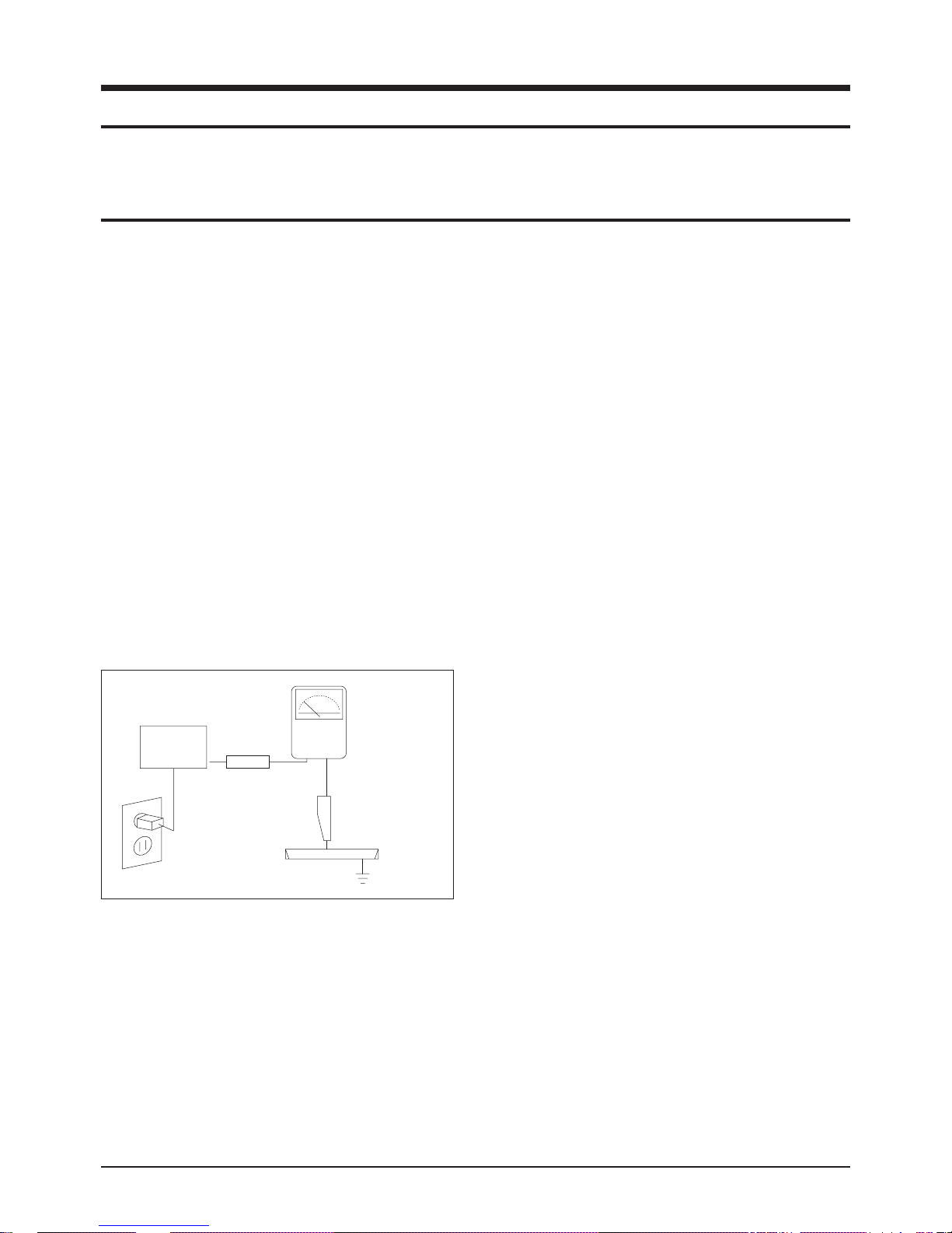
3. Check for Electricity Leakage (Figure 1-1)
Warning: Do not use an insulated transformer for checking the leakage. Use only those current leakage testers
or mirroring systems that comply with ANSIC 101.1 and
the Underwriter Laboratory's specifications (UL1410,
59.7).
Fig. 1-1 AC Leakage Test
4. A high voltage is maintained within the specified limits
using safety parts, calibration and tolerances. When
voltage exceeds the specified limits, check each special
part.
5. Warning for Engineering Changes:
Never make any changes or additions to the circuit
design or the internal part for this product.
Ex: Do not add any audio or video accessory
connectors. This might cause physical damage.
Furthermore, any changes or additions to the original
design/engineering will invalidate the warranty.
6. Warning - Hot Chassis:
Some TV chassis are directly connected to one end of
the AC power cord for electrical reasons.
Without insulated transformers, the product can only be
repaired safely when the chassis is connected to the
earthed end of the AC power source.
To make sure the AC power cord is properly connected,
follow the instructions below. Use the voltmeter to
measure the voltage between the chassis and the
earthed ground. If the measurement is over 1.0V, unplug
the AC power cord and change the polarity before reinserting it. Measure the voltage between the chassis
and the ground again.
7. Some TV chassis are shipped with an additional
secondary grounding system. The secondary system is
adjacent to the AC power line. These two grounding
systems are separated in the circuit using an
unbreakable/unchangeable insulation material.
8. When any parts, material or wiring appear overheated or
damaged, replace them with new regular ones
immediately. When any damage or overheating is
detected, correct this immediately and make a regular
check of possible errors.
9. Check for the original shape of the lead, especially that
of the antenna wiring, any sharp edges, the AC power
and the high voltage power. Carefully check if the wiring
is too tight, incorrectly placed or loose. Never change the
space between the part and the printed circuit board.
Check the AC power cord for possible damages. Keep
the part or the lead away from any heat-emitting
materials.
Precaution
Samsung Electronics 1-1
To avoid possible damages or electric shocks or exposure to radiation, follow the instructions below with regard to safety,
installation, service and ESD.
1. Precaution
1-1 Safety Precautions
(READING SHOULD
DEVICE
UNDER
TEST
EXPOSED METAL
2-WIRE CORD
ALSO TEST WITH
PLUG REVERSED
(USING AC ADAPTER
PLUG AS REQUIRED)
TEST ALL
SURFACES
LEAKAGE
CURRENT
TESTER
NOT BE ABOVE
0.5mA)
EARTH
GROUND

10. Safety Indication:
Some electrical circuits or device related materials
require special attention to their safety features, which
cannot be viewed by the naked eye. If an original part is
replaced with another irregular one, the safety or
protective features will be lost even if the new one has a
higher voltage or more watts.
Critical safety parts should be bracketed with ( ).
Use only regular parts for replacements (in particular,
flame resistance and dielectric strength specifications).
Irregular parts or materials may cause electric shock or
fire.
Precaution
1-2 Samsung Electronics
!

1. The service instructions are printed on the cabinet, and
should be followed by any service personnel.
2. Make sure to unplug the AC power cord from the power
source before starting any repairs.
(a) Remove or re-install parts or assemblies.
(b) Disconnect the electric plug or connector, if any.
(c) Connect the test part in parallel with the electrolytic
capacitor.
3. Some parts are placed at a higher position than the
printed board. Insulated tubes or tapes are used for this
purpose. The internal wiring is clamped using buckles to
avoid contact with heat emitting parts. These parts are
installed back to their original position.
4. After the repair, make sure to check if the screws, parts
or cables are properly installed. Make sure no damage is
caused to the repaired part and its surroundings.
5. Check for insulation between the blade of the AC plug
and that of any conductive materials (i.e. the metal
panel, input terminal, earphone jack, etc).
6. Insulation Check Process: Unplug the power cord from
the AC source and turn the switch on. Connect the insulating resistance meter (500v) to the AC plug blade.
The insulating resistance between the blade of the AC
plug and that of the conductive material should be more
than 1 ㏁.
7. Any B+ interlock should not be damaged.
If the metal heat sink is not properly installed, no
connection to the AC power should be made.
8. Make sure the grounding lead of the tester is connected
to the chassis ground before connecting to the positive
lead. The ground lead of the tester should be removed
last.
9. Beware of risks of any current leakage coming into
contact with the high-capacity capacitor.
10. The sharp edges of the metal material may cause
physical damage, so ensure wearing protective gloves
during the repair.
Precaution
Samsung Electronics 1-3
Warning 1: First carefully read the "Safety Instruction" in this service manual.
When there is a conflict between the service and the safety instructions, follow the safety instruction at all times.
Warning 2: Any electrolytic capacitor with the wrong polarity will explode.
1-2 Servicing Precautions

1-3 Static Electricity Precautions
1. Some semi-conductive ("solid state") devices are
vulnerable to static electricity. These devices are known
as ESD. ESD includes the integrated circuit and the field
effect transistor. To avoid any materials damage from
electrostatic shock, follow the instructions described
below.
2. Remove any static electricity from your body by
connecting the earth ground before handling any
semi-conductive parts or ass'ys. Alternatively, wear a
dischargeable wrist-belt.
(Make sure to remove any static electricity before
connecting the power source - this is a safety instruction
for avoiding electric shock)
3. Remove the ESD ass'y and place it on a conductive
surface such as aluminum foil to prevent accumulating
static electricity.
4. Do not use any Freon-based chemicals.
Such chemicals will generate static electricity that
causes damage to the ESD.
5. Use only grounded-tip irons for soldering purposes.
6. Use only anti-static solder removal devices.
Most solder removal devices do not support an
anti-static feature. A solder removal device without an
anti-static feature can store enough static electricity to
cause damage to the ESD.
7. Do not remove the ESD from the protective box until the
replacement is ready. Most ESD replacements are
covered with lead, which will cause a short to the entire
unit due to the conductive foam, aluminum foil or other
conductive materials.
8. Remove the protective material from the ESD
replacement lead immediately after connecting it to the
chassis or circuit ass'y.
9. Take extreme caution in handling any uncovered ESD
replacements. Actions such as brushing clothes or lifting
your leg from the carpet floor can generate enough static
electricity to damage the ESD.
Precaution
1-4 Samsung Electronics
CAUTION
These servicing instructions are for use by
qualified service personnel only.
To reduce the risk of electric shock do not
perform any servicing other than that contained in the
operating instructions unless you are qualified to do so.

Precaution
Samsung Electronics 1-5
1-4 Installation Precautions
1. For safety reasons, more than two people are required
for carrying the product.
2. Keep the power cord away from any heat emitting
devices, as a melted covering may cause fire or electric
shock.
3. Do not place the product in areas with poor ventilation
such as a bookshelf or closet. The increased internal
temperature may cause fire.
4. Bend the external antenna cable when connecting it to
the product. This is a measure to protect it from being
exposed to moisture. Otherwise, it may cause a fire or
electric shock.
5. Make sure to turn the power off and unplug the power
cord from the outlet before repositioning the product.
Also check the antenna cable or the external connectors
if they are fully unplugged. Damage to the cord may
cause fire or electric shock.
6. Keep the antenna far away from any high-voltage cables
and install it firmly. Contact with the high-voltage cable or
the antenna falling over may cause fire or electric shock.
7. Check the basics of the screen test.
- Image position/size, Tilt adjustment

1-6 Samsung Electronics
MEMO
Product Specification
Samsung Electronics 2-1
2. Product Specification
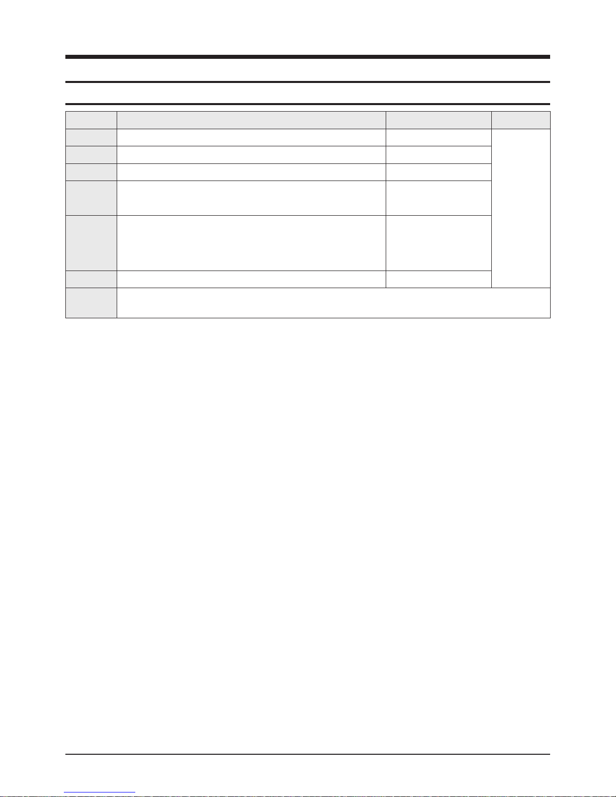
2-1 Product Features
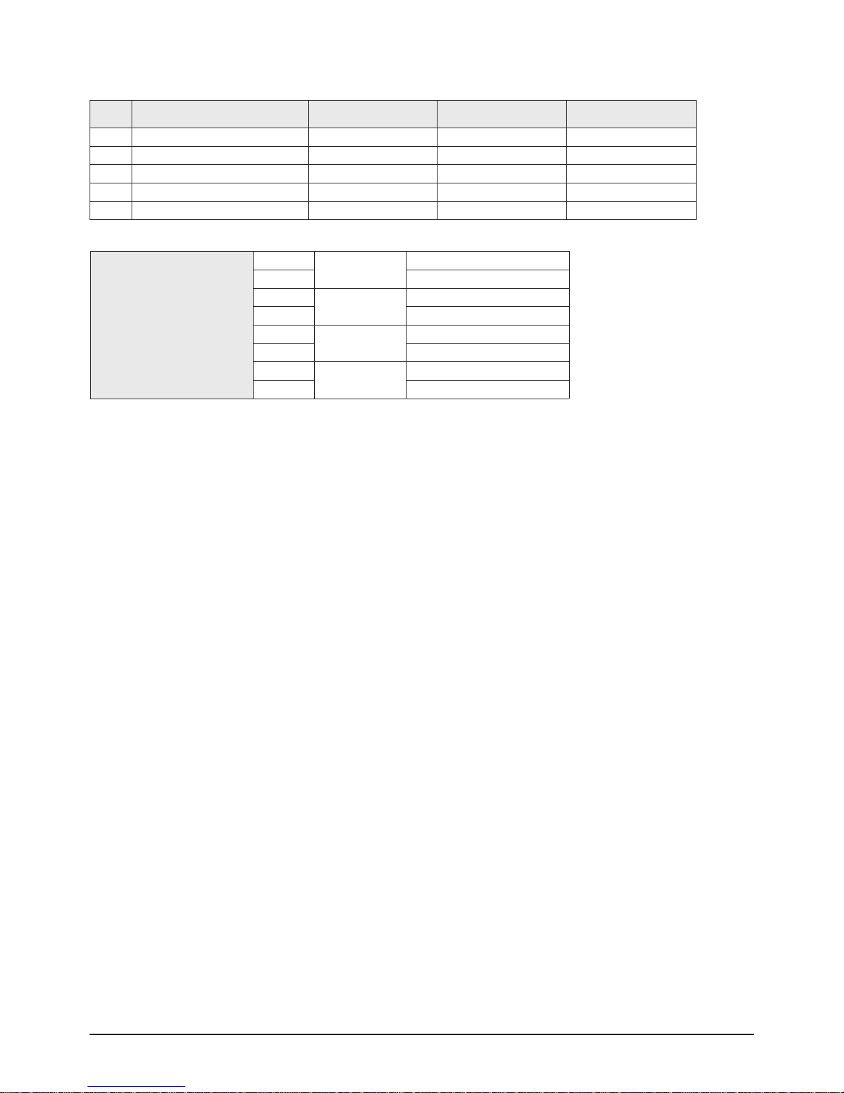
Block Specfication Core Parts Remark
CRT 29" SLIM FIT CRT SLIM FIT CRT
RF Part LNA F/S TUNER TDQ-6L/125S-A2, LNA
Power WORLD WIDE INPUT VOLTAGE RANGE STR-X6750B
Video
- MULTI SYSTEM(NT/PAL/SECAM)
- 1H Comb Filter
VCT 49X3F PY F1000
Audio
- Output : 10W X2
- Function : NICAM/A2 STEREO,
PSEUDO STEREO,
TURBO PLUS
VCT 49X3F PY F1000
TDA7297SA
Cabinet - 29" CABINET
Other
- BASIC MODEL : CS-29Z30ZQ
- TURBO→TURBO PLUS
■ Core Parts Functions
- VCT 49X3F PY F1000 : Video/Sound Processing
1
x MICOM
- X6750F : SMPS Power STR
- TDA7297SA : 5W ~ 15W Sound Output BTLAMP
- 24C161 : 16K EEPROM
- LA78045 : Vertical Deflection AMP
- FJAF6810A : H-OUT S/W TR
- TDQ-6L : F/S PAL Tuner(LNA Option)
- 6109JF : R/G/B Drive AMP IC
- Flyback Trans : FUH29A001V(11P,27KV)
Product Specification
2-2 Samsung Electronics
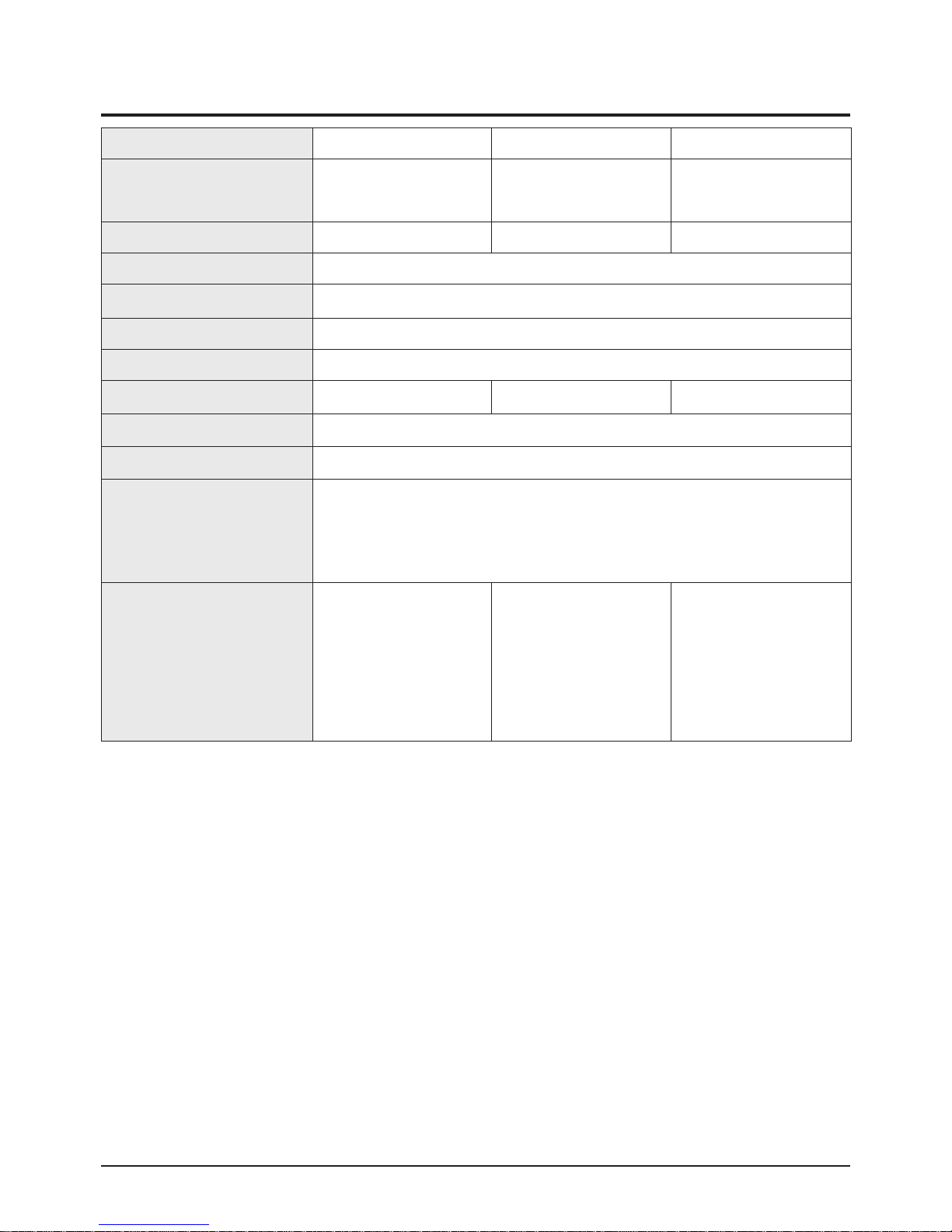
2-2 Key Features
Country EU CIS ASIA
COLOR
demodulation
PAL-BG / DK/ I
NT4.43, SECAM-L / L'
PAL-BG / DK / I
NTSC-M (CS SYSTEM)
PAL-BG / DK / I
NTSC-M (CS SYSTEM)
Sound receving way QSS (Quasi Split) QSS (Quasi Split) QSS (Quasi Split)
Sound demodulation INTER CARRIER (Virtual Dolby / Nicam / A2 Stereo)
Antemma 75 ohm Din-Jack
Channel search F/S
Channel numbers AIR (100Ch)
Input voltage AC 220V ~ 240V AC 160V - 300V AC 100V ~ 240V
Power system STR-X6750F
Power insulation SMPS / COLD
receving(P/G) CH
VHF LOW : 2 ~ 4
VHF HIGH : 5 ~ 13
UHF : 14 ~ 69
CATV : S1 ~ 41
Character
TTX
Melody on/off
Turbo Sound
Auto Volume
Pre-Ch'
LNA+ (Option)
Led : Red
TTX, LNA+
Melody on/off
Turbo Sound
Auto Volume
Pre-Ch'
LNA+ (Option)
Led : Red
TTX
Melody on/off
Turbo Sound
Auto Volume
Pre-Ch'
LNA+ (Option)
Led : Red
■ Feature
- AKB(Auto Kinetic Bais)
- Comb Filter : 1H Comb Filter
- Picture Size : 4:3/Zoom
- NICAM / STEREO / Line-STEREO
- Auto STEREO, Sound Equalizer, Auto Mute, Auto Volume Limit, PSEUDO STEREO, TURBO PLUS
- Composite (RCA A/V, DVD)
- Rear : 42P Scart Input/Output (Scart1 R/G/B Input)
- Front or Side A/V Input (Side A/V Preferability)
Product Specification
Samsung Electronics 2-3
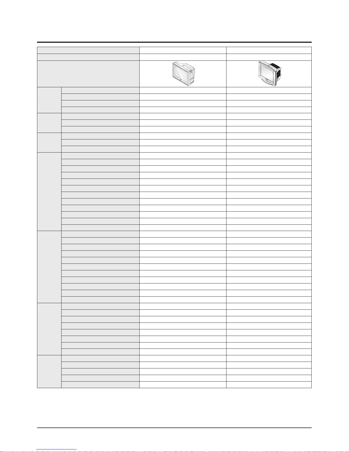
2-3 Specifications Analysis
Model CL-29M21FQ CS-29Z40MH
Chassis KS7B KS7C
Design
Basic
Product Type FLAT CRT FLAT CRT
Digital Display -
Screen Size 29 29
Aspect Ratio 4:3 4:3
System
Broadcasting System PAL/SECAM/NT PAL/SECAM
Tuner Programmable F/S Programmable F/S
CH Memory 100CH 100CH
Power
Supply 230V 110-250V
Stand-by 3W 3W
Picture ON Master S/W Master S/W
Picture
1H Comb-Filter O O
SCAN 50HZ 60HZ
Sharpness O O
CTI O X
VM X OPTION
AKB O O
P.STD O O
PIP X OPTION
Digital NR O O
Color Tone(W/B) O O
Black Level Expantion O O
Screen Mode 5 Mode 4 Mode
Sound
SPK System A11 Semi Dome/Direct Direct
Sound Output Power(Max) 5W+5W 10W+10W
MDB X X
Virtual Dolby X X
MSE X X
Melody O O
Turbo Sound O O
A2 Stereo A2 or Nicam A2 or Nicam
Auto Stereo O O
AVL O O
Equalizer O O
Jack
Front/Side AV Jack O O
PC Input(VGA) X X
Scart Jack 2Scart RCA 9P
Back A/V Monitor Out O O
S-VHS Jack(Front only) O OPTION
Head/Earphone Jack O X
Common Interface O O
Service Port X X
Accessory
I/B O O
Normal Remocon O O
Battery O O
Matching Trans O X
Rod ANT O X
Product Specification
2-4 Samsung Electronics
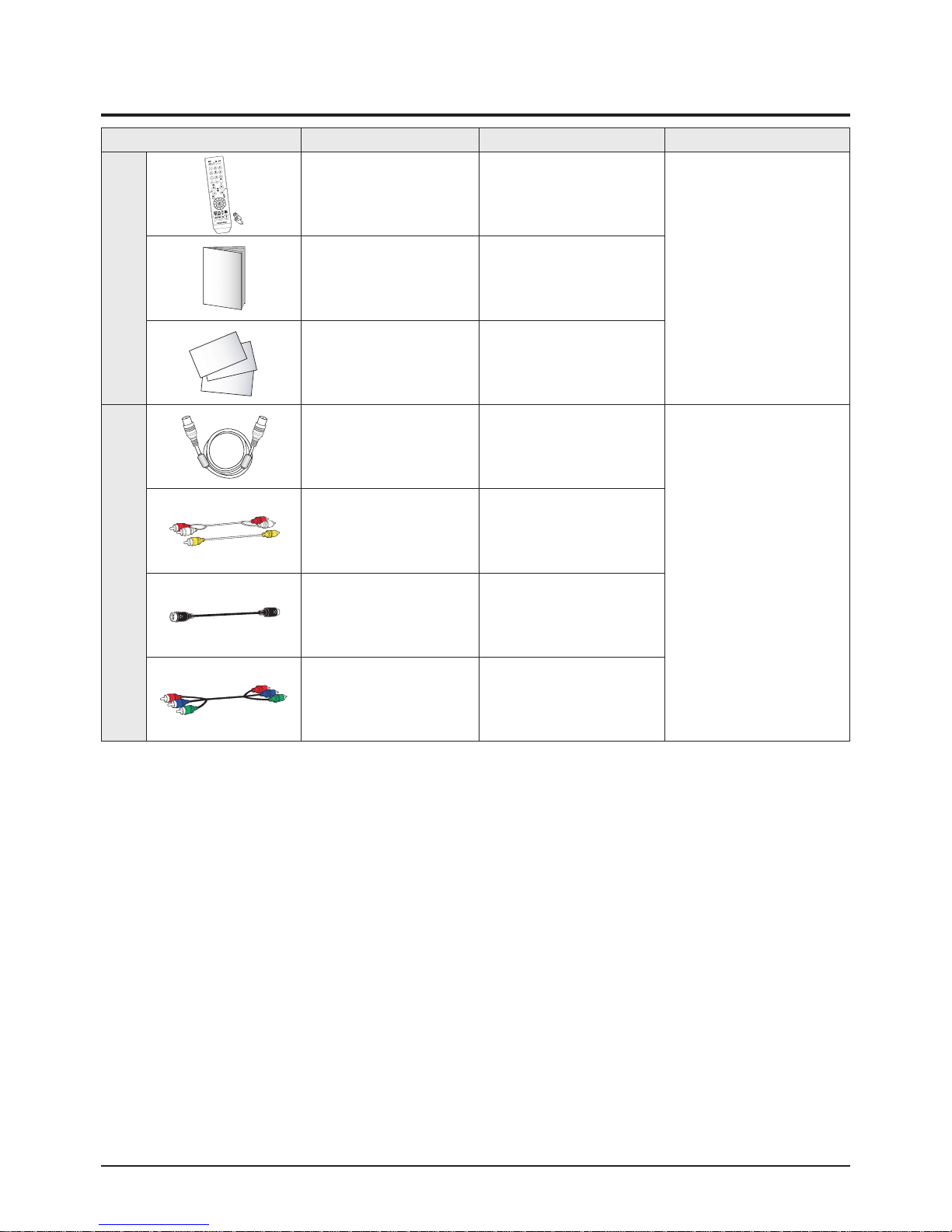
2-4 Accessories
Accessories Item Item code Remark
Supplied Accessories
Remote Control /
Alkaline Battery
(1.5V AAA)2EA
AA59-00399D/
4301-000121
Samsung Service centerOwner's Instructions AA68-03867A
Warranty Card
Safety Guide
Registration Card
-
AA68-03242G
-
Accessories that can be purchased
additionally
RF Cable -
Internal shopping mall
Video Cable /
Audio Cable
-
S-Video Cable -
Component Cable -

Alignment & Adjustment
Samsung Electronics 3-1
3. Alignment & Adjustment
3-1 Service Instruction
1. General Adjustment :
In general, a color TV can provide ideal visual quality by adjusting the basic settings such as the vertical size, horizontal size,
focus, etc.
Display a black and white picture on the screen to check if the picture is clearly displayed.
If there are some 'spotted' points on the screen when displaying a black and white picture, degauss the screen using the
degauss coil. If the spotted points remain, re-adjust the purity and the convergence.
This completes the basic performance examination.
Notice.
■ These adjustments and the check list are only applied to KS7C chassis-applied models.
■ Only use 230V for the measurement set. It is recommended using an insulation transformer when supplying power to
the set so as to prevent shock to the set or to yourself.
■ These adjustment specifications have been created on the basis of the domestic KS7C chassis-applied remote control
model. Some of the contents may be changed subject to the sales location and the product specifications.
※When replacing the Module Service Instruction
1. When replacing the MAIN Board : Tilt adjustment, Focus adjustment, Screen voltage, W/B adjustment are all required. Since
the settings including the Channel information,Deflection, etc. are saved to the EEPROM,
recogfigure these settings when replacing the MAIN Board.
The notation of the software information : T-GRN2PEU-1000 refer to "GREEN2 BASIC MODEL EUROPE. ver.1000"
Since the settings including the Channel information, Deflection, etc. are
saved to the EEPROM, recogfigure these settings when replacing the MAIN Board.
2. When replacing the CRT Ass'y : No adjustments required
3. When replacing the front panel Master Power switch : No adjustments required
4. When replacing the Side AV Ass'y : No adjustments required
5. When replacing the PIP Module : No adjustments required
6. When replacing the Control Ass'y : No adjustments required
7. When replacing the PFC Ass'y : No adjustments required
1. To enter Service Mode, press the keys on the remote control according to the following sequence. (in Stand-by status)
Info → Menu → Mute → Power On
※ When failing to enter Service Mode, repeat the procedure above.
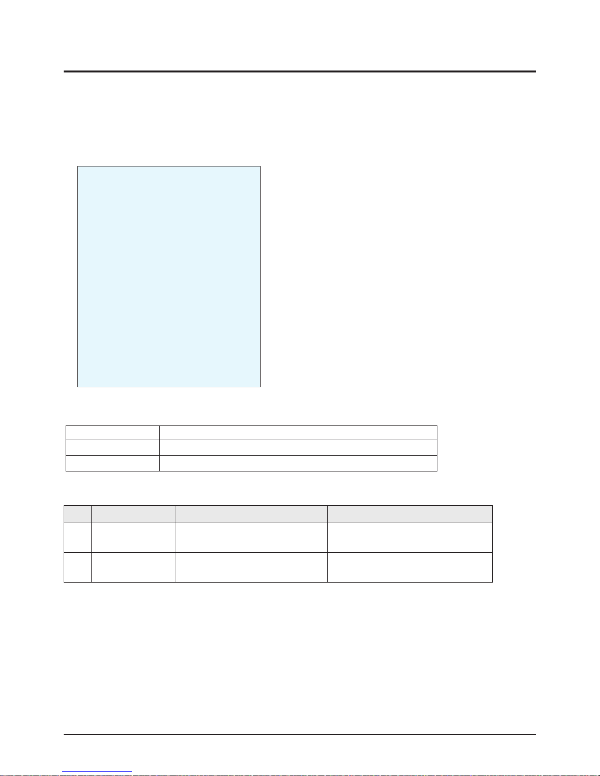
2. The initial screen of Service Mode.
3. Functions of the Keys within Service Mode.
4. W/B Setting
Alignment & Adjustment
3-2 Samsung Electronics
3-2 How to Access Service Mode
MENU Show all menus
▲ / ▼
Move the cursor to select an item.
◀ / ▶
Adjust the selected configuration value
Option1 XX XX XX XX XX
Option2
Deflection
WSS Deflection
Video Adjust1
Video Adjust2
Video Adjust3
Video Adjust4
Video Adjust5
YC Delay
Others
Bus Stop Off
CHECKSUM 0000
G2 Adjust
RESET
T-GRN2PEU-1000 2005/0X/XX
No Item Data Required Adjustment
1
White
Balance
x:300± 3 y:290± 3 Y:30± 3
White Balance (Standard Data)
2 Screen Voltage Same as KS7B Basic Model Basic Model
Alignment & Adjustment
Samsung Electronics 3-3
3-3 Factory Data
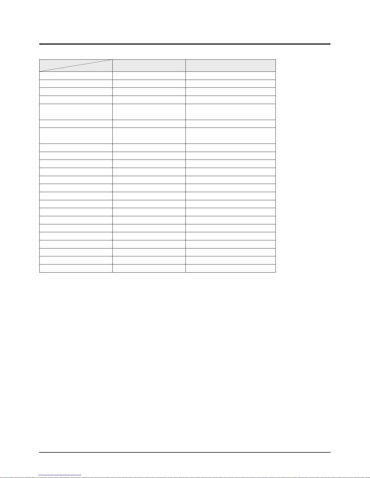
1. Option
CS29Z40ZQT Remark
Option
1. System CS CS, CZ, CW
2. Sound NICAM NICAM, V-Dolby, Line Stereo, A2
3. CRT 4 ; 3 4:3, WIDE
4. AV Jack 2SCART+S
2RCA+S+DVD, 2SCART, 2SCART+S,
2RCA, 2RCA+S, 2RCA+DVD
5. Max Beam Check Off On, Off
6. Txt Language Russian
West Europe, East Europe, Russian,
Greek-Turky, Arabic, Farsi, Arab-Hebrew
7. LNA On
On, Off → With CIS : ON
8. High Deviate Off On, Off
9. TTX On/Off ON On, Off
10. Double TTX Off
On, Off → CRT Wide Model
11. Tilt Off On, Off
12. Hotel Mode Off
On, Off → Hotel Mode : ON
13. Volume Curve Large Curve Large Curve, Small Curve
14. Osd Language CIS East-Asia, Middle-Asia, CIS, China
15. TTX List Pri Off On, Off
16. Search LNA Off On, Off
17. X-RAY Off On, Off
18. ALPS 2-TUNER Off On, Off
19. PIP Off 1-Tuner, 2-Tuner, Off
20. DNIe Jr Off On, Off
21. Antenna Disp Off On, Off
22. Equalizer On On, Off
Alignment & Adjustment
3-4 Samsung Electronics
2. Deflection
No Item Initial Data Remark
1 V Amp 12 12 ADJ
2 V Shift -59 -59 ADJ
3 H EW 5 5 ADJ
4 H Shift 104 105 ADJ
5 V Linearity 0 0 ADJ
6 V SC 45 49 FIX
7 H Parabola 80 80 ADJ
8 Upper Corner -19 -19 ADJ
9 Lower Corner -20 -20 ADJ
10 Upper Corner6 0 -4 FIX
11 Lower Corner6 0 -7 FIX
12 H Trapezium 1 1 ADJ
13 Bow 3 3 ADJ
14 Angle -2 -2 ADJ
15 EHT Time 20 20 FIX
16 EHT Threshold 1 1 FIX
17 EHT Vertical -12 0 FIX
18 EHT Horizontal 5 24 FIX
19 EHT Vertical2 -19 4 FIX
20 EHT Horizontal2 10 7 FIX
3. Deflection [NTSC Offset]
No Item Initial Data Remark
1 V Amp -2 -2 ADJ
2 V Shift 6 6 ADJ
3 H EW 0 0 ADJ
4 H Shift 14 14 ADJ
5 V Linearity -3 -3 ADJ
6 V SC 0 0 ADJ
7 H Parabola 0 0 ADJ
8 Upper Corner 0 0 ADJ
9 Lower Corner 0 0 ADJ
10 Upper Corner6 0 -4 FIX
11 Lower Corner6 0 -7 FIX
12 H Trapezium 0 0 ADJ
13 Bow 0 0 ADJ
14 Angle 0 0 ADJ
Alignment & Adjustment
Samsung Electronics 3-5
Alignment & Adjustment
3-6 Samsung Electronics
4. Video Adjust 1
No Item Initial Data Remark
1 R Cutoff 127 127 ADJ
2 G Cutoff 127 127 FIX
3 B Cutoff 127 127 ADJ
4 R Drive 127 127 ADJ
5 G Drive 127 127 FIX
6 B Drive 127 127 ADJ
7 Sub Bright 50 50 ADJ
8 Sub Contrast 55 55 ADJ
9 Sub Color 10 7 FIX
10 Sub Tint 52 52 FIX
11 AKB Option 1 1 FIX
12 BCL Threshold 20 19 FIX
13 BCL Gain 240 240 FIX
14 BCL Time 255 255 FIX
15 Sub Sharpness 12 6 FIX
16 DVD R Cutoff -5 -5 FIX
17 DVD B Cutoff -4 -4 FIX
18 BCL TUCP 100 100 FIX
19 SECAM Sub Color 10 2 FIX
20 NTSC Sub Color 10 7 FIX
21 Pilot Low [NTSC Only] - - FIX
22 Pilot High [NTSC Only] - - FIX
23 V-Mute [x100ms,NTSC Only] - - FIX
5. Video Adjust 2
No Item Initial Data Remark
1 VSU 2 2 FIX
2 Melody Volume 10 10 FIX
3 HB Start 159 159 FIX
4 HB Stop 159 159 FIX
5 RF AGC 4 4 FIX
6 VM Gain 0 3 FIX
7 VM Delay 0 10 FIX
8 V Peaking 0 0 FIX
9 BLE Tilt 6 6 FIX
10 BLE Gain 1 1 FIX
11 BLE Mode 2 2 FIX
12 BLE Break 1 1 FIX
13 CTI Gain 0 3 FIX
14 CTI Coring 0 5 FIX
15 LTI Gain 0 15 FIX
16 D-EHT Time 5 5 FIX
17 DCT Ratio 50 50 FIX
18 LTI Enable 0 1 FIX
19 VSP_Comb 0 0 FIX
Alignment & Adjustment
Samsung Electronics 3-7
6. Video Adjust 3
No Item Initial Data Remark
1 NR Value 3 3 FIX
2 Gamma Mode 1 1 FIX
3 Gamma Correction 40 70 FIX
4 BST Start Point 125 125 FIX
5 BST Gain(B) 50 50 FIX
6 DPWL Gain 60 80 FIX
7 DPWL Start 145 185 FIX
8 SECAM DR 1 2 FIX
9 SECAM DB 1 1 FIX
10 PIP Contrast 10 15 FIX
11 PIP TINT 0 0 FIX
12 PIP Color 7 10 FIX
13 PIP PAL V.Pos 24 24 FIX
14 PIP NTSC V.Pos 23 23 FIX
15 PIP H.Pos 39 39 FIX
16 PIP R Cutoff 2 2 FIX
17 PIP B Cutoff 1 1 FIX
18 PIP R Drive 138 138 FIX
19 PIP B Drive 134 134 FIX
7. YC Delay
No Item Initial Data Remark
1 PAL Delay -3 -3 FIX
2 SECAM Delay -3 -3 FIX
3 NTSC Delay -3 -3 FIX
4 PAL (AV) Delay -1 -1 FIX
5 SECAM (AV) Delay -3 -3 FIX
6 NTSC (AV) Delay -3 -3 FIX
Alignment & Adjustment
3-8 Samsung Electronics
8. G2 Adjust
No Item Initial Data Remark
1 IBRM 175 180 FIX
2 WDRV 25 50 FIX
3 CDL 250 254 FIX
4 COLR G B 150,150,150 50,50,50 FIX
5 RESET
WHITE BALANCE
H
E-Asia
265 / 265 / 40
L
265 / 265 / 3.0
H
Russia
285 / 290 / 30
L
286 / 290 / 1.5
H
Australia
292 / 307 / 40
L
301 / 311 / 3.0
H
Middle East
290 / 300 / 40
L
290 / 300 / 3.0

Alignment & Adjustment
Samsung Electronics 3-9
No Factory Control MIN MAX INITIAL Remark
0 Dynamic Contrast 0 255 100 FIX
1 Dynamic Brightness 0 255 45 FIX
2 Dynamic Sharpness 0 255 75 FIX
3 Dynamic Color 0 255 55 FIX
4 Dynamic Tint 0 255 50 FIX
5 Standard Contrast 0 255 80 FIX
6 Standard Brightness 0 255 50 FIX
7 Standard Sharpness 0 255 50 FIX
8 Standard Color 0 255 50 FIX
9 Standard Tint 0 255 50 FIX
10 Movie Contrast 0 255 50 FIX
11 Movie Brightness 0 255 55 FIX
12 Movie Sharpness 0 255 25 FIX
13 Movie Color 0 255 40 FIX
14 Movie Tint 0 255 50 FIX
15 255
16 255
17 255
18 255
19 DVD SUB TINT 0 255 17 FIX
20 16:9 V-SHIFT 0 255 15 FIX
21 16:9 PARAVOLA 0 255 5 FIX
22 PIP BRIGHTNESS 0 255 160 FIX
23 Double TTX Contrast 0 255 255 FIX
24 TTX V Position 0 255 35 FIX
25 TTX H Position 0 255 148 FIX
26 TTX Contrast 0 255 85 FIX
27 TTX Brightness 0 255 20 FIX
28 OSD/PIP Contrast 0 255 115 FIX
29 OSD/PIP Brightness 0 255 15 FIX
30 Double TTX H Position 0 255 225 FIX
31 Standard Equ100(Std BASS) 0 255 8 FIX
32 Standard Equ300(Std TREBLE) 0 255 13 FIX
33 Standard Equ1K(Music BASS) 0 255 14 FIX
34 Standard Equ3K(Music TREBLE) 0 255 13 FIX
35 Standard 10K(Movie BASS) 0 255 12 FIX
36 Music Equ100(Movie TREBLE) 0 255 18 FIX
37 Music Equ300(Speech BASS) 0 255 14 FIX
38 Music Equ1K(Speech TREBLE) 0 255 11 FIX
39 Music Equ3K 0 255 14 FIX
40 Music 10K 0 255 18 FIX
41 Movie Equ100 0 255 22 FIX
42 Movie Equ300 0 255 15 FIX
43 Movie Equ1K 0 255 11 FIX
44 Movie Equ3K 0 255 12 FIX
45 Movie 10K 0 255 13 FIX
46 Speech Equ100 0 255 6 FIX
9. EEPROM SubAddress

Alignment & Adjustment
3-10 Samsung Electronics
No Factory Control MIN MAX INITIAL Remark
47 Speech Equ300 0 255 11 FIX
48 Speech Equ1K 0 255 14 FIX
49 Speech Equ3K 0 255 13 FIX
50 Speech 10K 0 255 11 FIX
51 Brightness(RGB/DVD) 0 255 13 FIX
52 Contrast(RGB/DVD) 0 255 38 FIX
53 U Saturation(RGB/DVD) 0 255 44 FIX
54 V saturation(RGB/DVD) 0 255 43 FIX
55 V/FBL Delay 0 255 85 FIX
56 CrCb Delay 0 255 84 FIX
57 d/w h-position 0 255 58 FIX
58 d/w -blanking 1 0 255 129 FIX
59 d/w -blanking 2 0 255 150 FIX
60 PIP G CUTOFF 0 255 2 FIX
61 PIP G DRIVE 0 255 135 FIX
62 OSD/PIP BRIGHT BALANCE 0 255 31 FIX
63 PIP BRIGHT OFFSET 0 255 85 FIX
64 MDB_STRENGTH 0 255 68 FIX
65 MDB_HARMONIC 0 255 37 FIX
66 MDB_HP 0 255 9 FIX
67 MDB_LP 0 255 11 FIX
68 MDB_LIM 0 255 252 FIX
69 MDB_CUTOFF 0 255 12 FIX
70 EHT POSITION 1 0 255 5 FIX
71 EHT POSITION 2 0 255 249 FIX
72 THRSEL 0 255 0 FIX
73 SLLTHD 0 255 1 FIX
74 LNAµ¿ÀÛÁ¡ 0 255 80 FIX
75 SLLTHDV(TV NO NOISE) 0 255 5 FIX
76 LNA Default 0 255 55 FIX
77 LNA SW 0 255 1 FIX
78 LMIXOFS 0 255 31 FIX
79 HOUTDEL 0 255 72 FIX
80 Over Modulation Detect 0 255 64 FIX
81 Over Mod. <-> Normal Return 0 255 100 FIX
82 VCR Mode Detect Counter 0 255 7 FIX
83 Sub Matrix Tint 0 255 4 FIX
84 Video Sub Sharpness 0 255 15 FIX
85 S Video Sub Sharpness 0 255 13 FIX
86 DVD Sub Sharpness 0 255 13 FIX
87 VZOOM 0 255 54 FIX
88 CR_P Data (Co_ch) 0 15 0 FIX
89 Hotel Mode Initial Volume 0 100 0 FIX
90 Standard Bass 0 255 50 FIX
91 Standrad Treble 0 255 50 FIX
92 Music Bass 0 255 85 FIX
93 Music Treble 0 255 70 FIX
94 Movie Bass 0 255 95 FIX

Alignment & Adjustment
Samsung Electronics 3-11
No Factory Control MIN MAX INITIAL Remark
95 Movie Treble 0 255 50 FIX
96 Speech Bass 0 255 40 FIX
97 Speech Treble 0 255 50 FIX
170 dynamic NR(Under 50dB) 0 31 15 FIX
171 dynamic NR(Under 45dB) 0 31 20 FIX
172 dynamic NR(Under 40dB) 0 31 25 FIX
173 dynamic NR(Under 35dB) 0 31 31 FIX
174 dynamic NR(Under 30dB) 0 31 31 FIX
175 dynamic NR(Under 25dB) 0 31 31 FIX
176 SCMIDL 0 3 1 FIX
177 SECACCL 0 7 2 FIX
178 VID_AMP_HEAD_BS(Over Mod) 0 - 56 FIX
179 CR_P (Over Mod) 0 - 2 FIX
181 2'nd Over Mod.detect 0 255 255 FIX
182 2'nd Over Mod.ON/OFF 0 255 255 FIX
185 EEP_BC_MIN_LIMIT 0 255 150 FIX
Alignment & Adjustment
3-12 Samsung Electronics
3-4 Service Adjustment
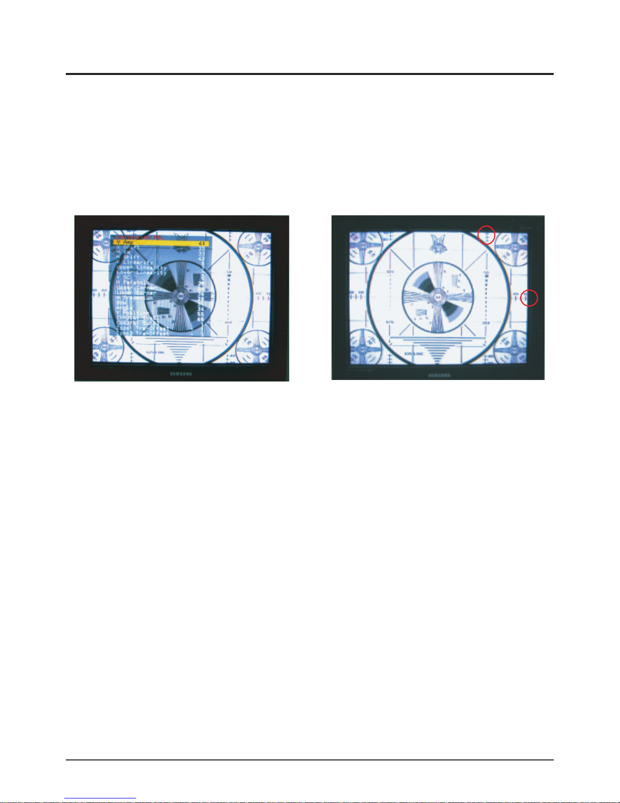
3-4-1 Adjusting the Picture Size
■ Since the KS7C chassis has the deflection settings data within the Factory Data, the picture size has to be adjusted when
replacing the Main Board or the VCTi Module, according to the following procedures.
① Display the Lion pattern. ② Press "Power Off →Info → Menu → Mute → Power On"
using the remote control and enter Factory Mode.
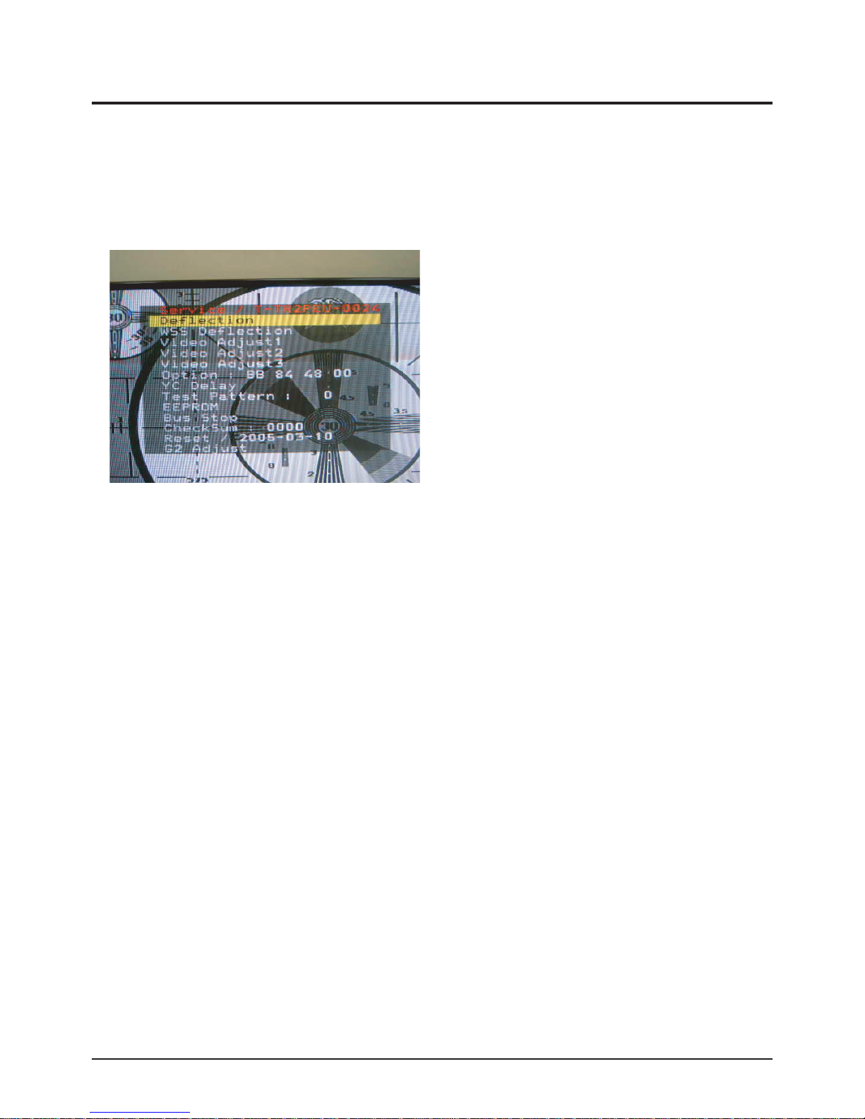
③ Enter Deflection Mode. ④ Adjust the V-AMP, V-SHIFT, H-AMP and H-SHIFT items so
that the width becomes 5 and the height becomes 4.
90
90
Alignment & Adjustment
Samsung Electronics 3-13
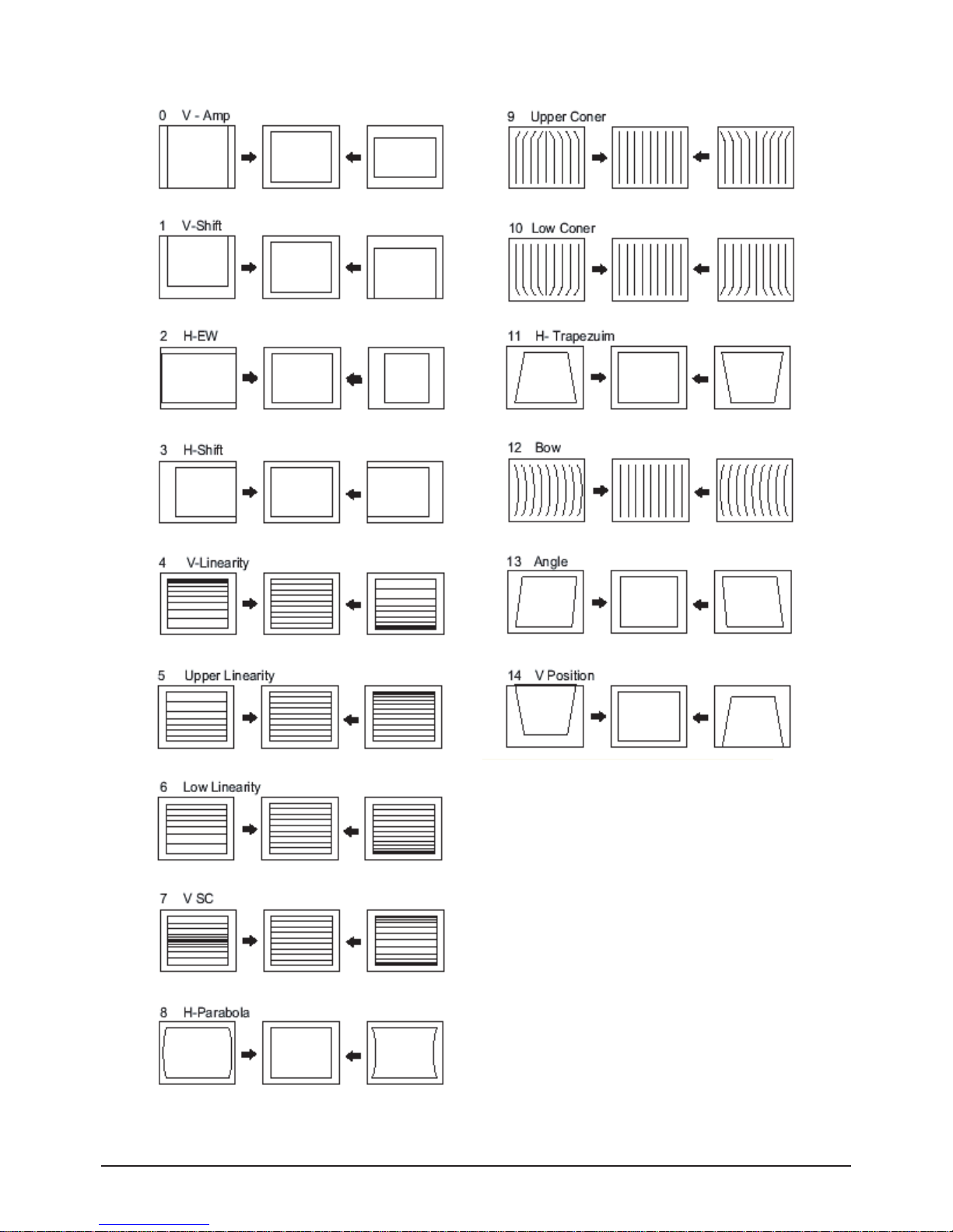
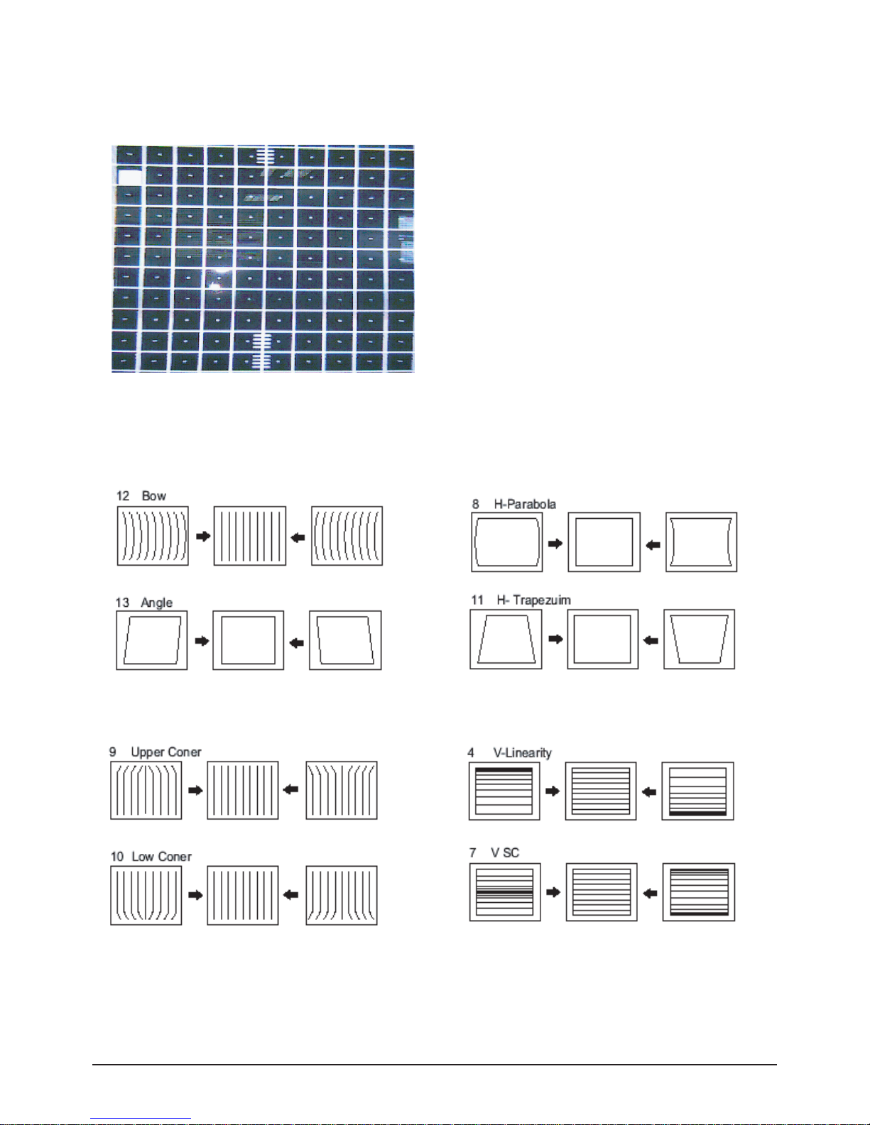
3-4-2 Adjusting the Picture Straight Lines
① Display the Cross Hatch pattern.
② Adjust settings other than V-AMP, V-SHIFT, H-AMP and H-SHIFT so that straight lines are displayed without curves.
⑦ When the adjustments are complete, display the Lion pattern and check that the picture size has not been changed.
If there is no change, finish the adjustments.
③ Adjust BOW and the Angle settings so that the center line
becomes a straight line.
④ Adjust the H-Parabola and H-Trapezium settings so that
the left and right lines become straight.
⑤ Adjust the Upper Corner and the Low Corner settings so that
the end of the lines become straight.
⑥ Adjust the V-Linearity and V-SC settings so that the
intervals of the horizontal lines become uniform.
Alignment & Adjustment
3-14 Samsung Electronics
3-5 Software Upgrade
3-5-1 Checking the Version of the Software (Analog SW)
1. To enter Service Mode, press the keys on the remote control according to the following sequence. (in Stand-by status)
Info → Menu → Mute → Power On
2. When entering Service mode, the software information is displayed at the top of the service mode menu OSD.
ex) T-GRN2PEU-1000 2005/0X/XX
Alignment & Adjustment
Samsung Electronics 3-15
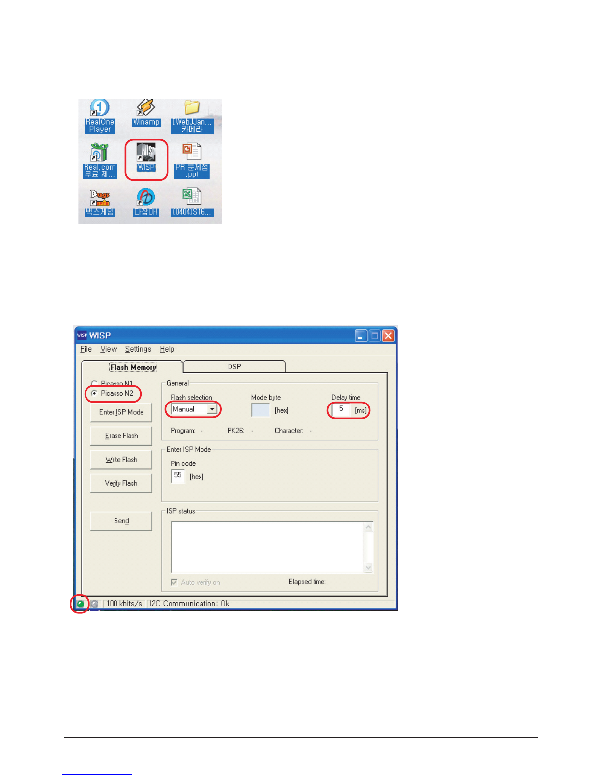
3-5-2 Service Download Procedure
1. Double click the your desktop “WISP” icon.
2. Check the standard
- Check the appoint “Picasso N2”
- Check the “Flash selection” item is appoint “Manual”
- You can adjust program delay time for program speed
but we use the normal “5[ms]”
- Check the green lamp if this is sometime red lamp you can not programming
Alignment & Adjustment
3-16 Samsung Electronics
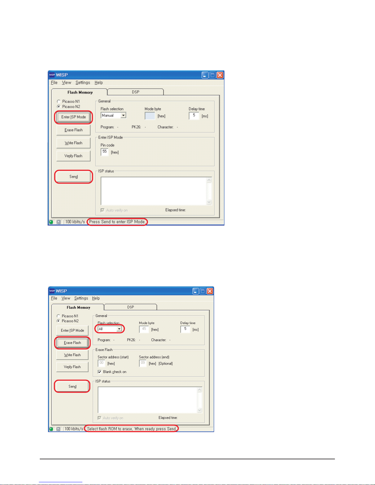
3. Check the IIC line
- Click the “Enter ISP Mode” button For IIC bus line problem or not
- Change the “Press Send to enter ISP Mode”
- Click the “Send” button
4. Erase before program
- Click the “Erase Flash” button for before program erase
- You can select flash selection item but we use normal “All” mode
- Change the “Select flash ROM to erase. When ready press Send.”
- Click the “Send” button
 Loading...