

Samsung CS21M21EHVXHAC, CS29M16MQUXXSE User Manual
COLOR TELEVISION RECEIVER
Chassis : KS7A(P)Rev.1
Model : CS21M21EHVXHAC
CS29M16MQUXXSE
COLOR TELEVISION RECEIVER CONTENTS
1.
2.
3.
4.
5.
6.
Specifications
Alignment and Adjustments
Exploded Views and Parts List
Electrical Parts List
PCB Diagram
Schematic Diagrams
SERVICE
Manual

This Service Manual is a property of Samsung Electronics Co.,Ltd.
Any unauthorized use of Manual can be punished under applicable
International and/or domestic law.
© Samsung Electronics Co., Ltd. Mar. 2005
Printed in Korea
AA82-02359A
ELECTRONICS
Exploded View & Parts List
Samsung Electronics 3-1
3. Exploded View & Parts List
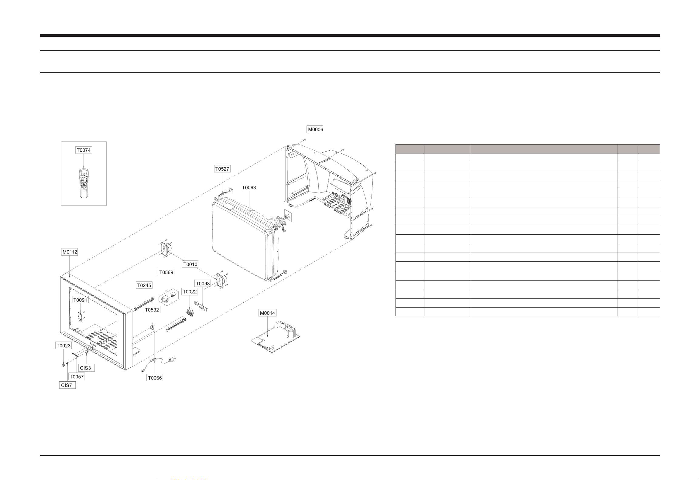
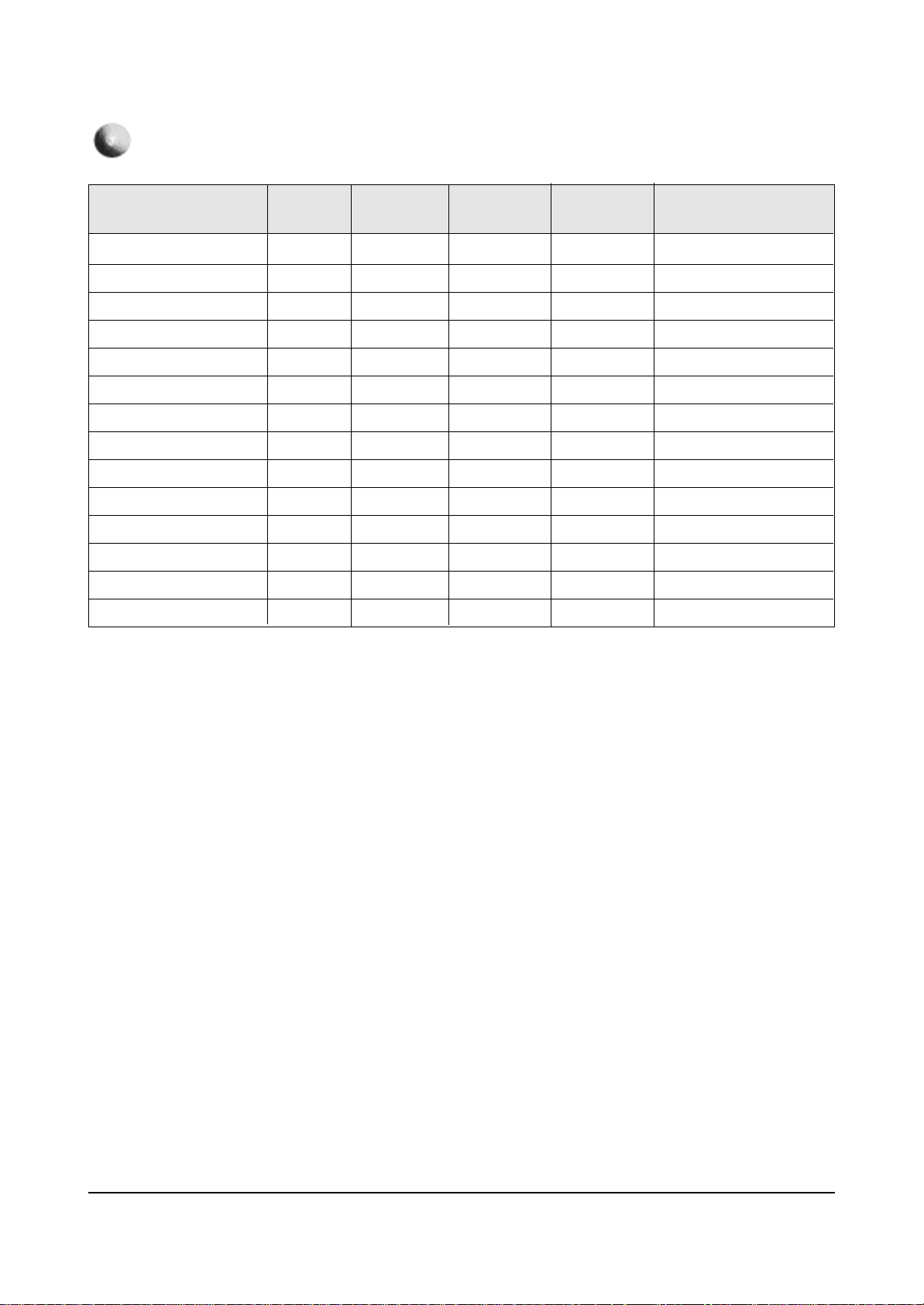
3-1 CS21M21EHVXHAC
You can search for the updated part code through ITSELF web site.
URL : http://itself.sec.samsung.co.kr
Loc.No Code No Description;Specification Q’ty S.N.A
CIS3 AA64-04048B DECORATION-POWER;21,29M21,ABS,HB,WHT,SVM 1 S.N.A
CIS7 AA61-60003J SPRING ETC-CS;-,SUS304,-,-,OD6,N7,OD6,-, 1 S.N.A
M0006 AA63-00927A COVER-REAR;21M21,SAVINA,SIEL,HIPS,HB,G43 1 S.N.A
M0014 AA94-15341B ASSY PCB MAIN;CS21M21EHVXHAC,KS7A 1
M0112 AA63-00926J COVER-FRONT;21M21,TSE,SAVIN,SIEL,HIPS,HB 1 S.N.A
T0022 AA64-04050A KNOB CONTROL;29M21,ABS,HB,G3676,BLM1404 1 S.N.A
T0023 AA64-04049A KNOB POWER;29M21,ABS,HB,G3676,SVM3012 1 S.N.A
T0057 AA64-70123A BADGE-BRAND;NEW,AL,L50,FLAT,SILVER,SAMSU 1
T0063 AA03-00403A CRT COLOR;A51QDX993X,0MG,1.75MH,18MH,3.1 1
T0066 AA96-20109C ASSY POWER CORD;-,CP2/NO(4.0),H/C300,KKP 1 S.N.A
T0074 AA59-00326E REMOCON;CS29M6PF,TM76,43,G6148,PAL,ET/KS 1
T0010 AA91-00427A ASSY HOLDER SPK;-,PP,8OHM/15W,BLK,SEMI-D 1
T0091 AA95-03194A ASSY SUB PCB-SIDE A/V;S56A,B-LOT 1
T0098 AA94-15080A ASSY PCB MISC-CONTROL;29M21,ET,KS7A 1 S.N.A
T0245 AA61-00711D HOLDER-PCB;29U1,U2,HIPS VO,BK502(HB-PROP 2 S.N.A
T0527 AA65-00009B CLAMPER CORE-D,COIL;21A8,NYLON 66,V0,-,- 4
T0569 AA94-15213A ASSY PCB MISC-MASTER;M21,KS7A,ET 1 S.N.A
T0592 AA64-04051A WINDOW-CONTROL;29M21,PC,CLEAR 1 S.N.A
Exploded View & Parts List
3-2 Samsung Electronics
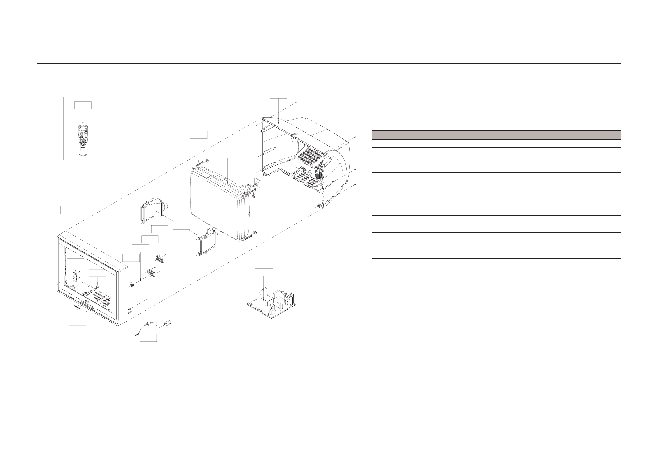
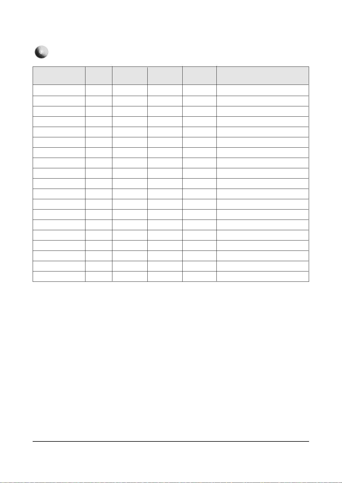
3-2 CS29M16MQUXXSE
You can search for the updated part code through ITSELF web site.
URL : http://itself.sec.samsung.co.kr
Loc.No Code No Description;Specification Q’ty S.N.A
CIS7 AA61-60003J SPRING ETC-CS;-,SUS304,-,-,OD6,N7,OD6,-, 1 S.N.A
M0014 AA94-15168C ASSY PCB MAIN;CS29M16MQUXXSE,KS7A 1 S.N.A
T0003 AA64-03818L CABINET FRONT;29M16,TSE,HIPS,T3.0,HB,G43 1 S.N.A
T0015 AA64-03819F CABINET BACK;29M16,HQ,TTSEC,TSE,HIPS,HB, 1
T0022 AA64-03822A KNOB-CONTROL;29M16,ABS,HB,G3676,SVM3012 1 S.N.A
T0023 AA64-03823A KNOB-POWER;29M16,ABS,HB,G3676,SVM3012 1 S.N.A
T0057 AA64-70117B BADGE-BRAND;,AL,T1.5,10.6,L65,BLK,SILVER 1
T0061 AA64-03824A WINDOW-REMOCON;29M16,PC,CLEAR 1 S.N.A
T0063 AA03-00400A CRT COLOR;A68QCP693X500,0MG,1.1MH,14.9MH 1
T0074 AA59-00312A REMOCON;DEEP IMPACT,TM75,36,TTX,EX,PAL 1
T0091 AA94-14077C ASSY PCB MISC-A/V SIDE;29M6,GOLDRUSH 1
T0010 AA91-00507A ASSY HOLDER SPK;-,-,8OHM/15W,-,ASSY HOLD 1
T0268 AA39-10006X CBF-POWER CORD;-,KKP419C,KLCE-2F,2.286MT 1
T0527 AA61-01373A HOLDER-D COIL;29K5,NYLON 66 4 S.N.A
T0607 AA61-40113A STOPPER-PCB;501H,HIPS,-,-,HB,NTR,- 1
T0074
T0015
T0003
T0091
T0607
T0023
CIS7
T0022
T0061
T0010
T0527
T0063
M0014
T0057
T0268

Alignment and Adjustments
Samsung Electronics 2-1
2. Alignment and Adjustments
2-1 General Alignment Instructions
1. Usually, a color TV-VCR needs only slight
touch-up adjustment upon installation. Check
the basic characteristics such as height,
horizontal and vertical sync and focus.
2. Observe the picture for good black and white
details. There should be objectionable color
shading; if color shading is present,
demagnetize, perform purity and convergence
adjustments described below.
3. Use the specified test equipment or its
equivalent.
4. Correct impedance matching is essential.
5. Avoid overload. Excessive signal from a
sweep generator might overload the front-end
of the TV. When inserting signal markers, do
not allow the marker generator to distort test
results.
6. Connect the TV only to an AC power source
with voltage and frequency as specified on the
backcover nameplate.
7. Do not attempt to connect or disconnect any
wires while the TV is turned on. Make sure
that the power cord is disconnected before
replacing any parts.
8. To protect against shock hazard, use an
isolation transformer.
2-2 Automatic Degaussing
A degaussing coil is mounted around the
picture tube, so that external degaussing after
moving the TV should be unnecessary. But
the receiver must be properly degaussed upon
installation.
The degaussing coil operates for about 1
second after the power is switched ON. If the
set is moved or turned in a different direction,
the power should be OFF for at least 10
minutes.
If the chassis or parts of the cabinet become
magnetized, poor color purity will result. If
this happens, use an external degaussing coil.
Slowly move the degaussing coil around the
faceplate of the picture tube and the sides and
front of the receiver. Slowly withdraw the coil
to a distance of about 6 feet before turning
power OFF.
If color shading persists, perform the
following Color purity and Convergence
adjustments.
2-3 High Voltage Check
CAUTION : There is no high voltage adjustment
on this chassis. The B+ power supply should be
+135 volts (with full color- bar input and normal
picture level).
1. Connect a digital voltmeter to the second
anode of the picture tube.
2. Turn on the TV. Set the Brightness and
Contrast controls to minimum (zero beam
current).
3. Adjust the Brightness and contrast controls to
both extremes. Ensure that the high voltage
does not exceed 30 KV under any conditions.

Alignment and Adjustments
2-2 Samsung Electronics
2-4 FOCUS Adjustment
1. Iput a crosshatch pattern.
2. Adjust the tuning control for the clearest picture.
3. Adjust the FOCUS control for well defined scanning lines in the center area of the screen.
2-5 SCREEN Adjustment
1. Input Toshiba Pattern
If a Toshiba pattern is not available,
Enter “Service Mode” and
select “Test pattern 2”(Toshiba pattern)
2. Enter “Service Mode”.
3. Select “G2-Adjust”.
4. Set the values as example
5. Turn the SCREEN VR until “Read Cutoff” and “Read Drive” are green.
(The incorrect SCREEN Voltage may result that “Read Cutoff” and “Read Drive” should be red)
ex) IBRM = 175
WDRV = 110
CDL = 250
COLR G B = 110 110 110
2-6 White Balance Adjustment
1. Warm up the TV set for at least 30 minutes.
2. Enter the Service Mode by pressing the remote control keys in the following sequence:
Power Off ➞ Info ➞ Menu ➞ Mute ➞ Power On
3. Initialize all set data.
4. Input a Toshiba pattern.
5. Using a probe(CA100), do the White Balance adjustments.
(1) Adjust Low-Light.
- Adjust Sub Brightness to set Y.
- Adjust B Cutoff to set y.
- Adjust R Cutoff to set x.
(2) Adjust High-Light.
- Adjust Sub Contrast to set Y.
- Adjust B Drive to set y.
- Adjust R Drive to set x.
(3) Check the value of Low-Light. If necessary, readjust Low-Light.
(4) Check the value of High-Light. If necessary, readjust High-Light.

2-8 Factory Adjustment
1. To enter the “Service Mode”, Press the remote-control keys in this sequence :
- If you do not have Factory remote-control
- If you have Factory remote-control
2-8-1 Service Mode
Alignment and Adjustments
Samsung Electronics 2-3
2-7 When adjusting Screen Voltage and White Balance
1. Screen Voltage and White Balance are related each other. Make sure both adjustments are correct.
2. Adjust Screen Voltage before White Balance Adjustments. Make sure Screen Voltage is correct.
3. If White Balance has been readjusted, re-check Screen Voltage.
4. After adjustments are complete, check the following.
- If spots appear on the screen after pressing the Power On/Off key, readjust Screen Voltage.
- If flyback lines appear on the screen, readjust Screen Voltage.
PICTURE OFF PICTURE ON
PICTURE ON
INFO
()
()
INFO
MENU
MUTE
FACTORY

Alignment and Adjustments
2-4 Samsung Electronics
2-8-2 Factoy Mode OSD
SERVICE / T - ETPAS0 - 10XX
Deflection
Video Adjust1
Video Adjust2
Video Adjust3
Option : D2 16 04 02
YC Delay
Test Pattern : 0
EEPROM
Bus Stop
Check Sum : 0000
Reset / 2004-03-08
G2 Adujust
2-8-2(A) ADJUST
127
127
127
180
127
127
127
127
127
127
127
127
127
127
255
255
127
127
127
127
Item Min
Max
-128
-128
-128
32
-128
-128
-128
-128
-128
-128
-128
-128
-128
-128
0
0
-128
-128
-128
-128
Remark
Adjust
Adjust
Adjust
Adjust
Adjust
FIX(Depend on the inch)
Adjust
Adjust
Adjust
FIX(Depend on the inch)
FIX(Depend on the inch)
Adjust
Adjust
Adjust
FIX
(Depend on the inch&CRT Drive)
FIX(Depend on the inch&CRT Drive)
FIX(Depend on the inch&CRT Drive)
FIX(Depend on the inch&CRT Drive)
FIX(Depend on the inch&CRT Drive)
FIX(Depend on the inch&CRT Drive)
V Amp
V Shift
H EW
H Shift
V Linearity
V SC
H Parabolra
Upper Corner
Lower Corner
Upper Corner 6
Lower Corner 6
H Trapezium
Bow
Angle
EHT Time
EHT Threshold
EHT Vertical
EHT Horizontal
EHT Vertical2
EHT Horizontal2
DEFLECTION : PAL
ET
24
-35
25
124
0
43
62
-5
-5
-4
-4
-3
3
1
20
1
-12
5
-19
10
Alignment and Adjustments
Samsung Electronics 2-5
G/R
12
-59
5
105
0
43
80
-19
-39
0
0
1
3
-2
20
1
-12
5
-19
10
Alignment and Adjustments
2-6 Samsung Electronics
127
127
127
180
127
127
127
127
127
127
127
127
127
127
Item Min
Max
-128
-128
-128
32
-128
-128
-128
-128
-128
-128
-128
-128
-128
-128
Remark
FIX
FIX
FIX
FIX
FIX
FIX
FIX
FIX
FIX
FIX
FIX
FIX
FIX
FIX
V Amp
V Shift
H EW
H Shift
V Linearity
V SC
H Parabolra
Upper Corner
Lower Corner
Upper Corner 6
Lower Corner 6
H Trapezium
Bow
Angle
DEFLECTION : NTSC OFFSET
ET
-2
6
0
14
-3
0
0
0
0
0
0
0
0
0
G/R
-2
6
0
14
-3
0
0
0
0
0
0
0
0
0

Alignment and Adjustments
Samsung Electronics 2-7
Video Adjust 1
255
255
255
255
255
255
100
63
23
63
1
127
255
255
15
10
10
255
127
127
15
Item Min
Max
0
0
0
0
0
0
0
0
0
0
0
-128
0
0
0
-10
-10
0
10
10
0
Remark
Adjust
FIX
Adjust
Adjust
FIX
Adjust
Adjust
Adjust
FIX(Depend on the country&CRT Drive)
FIX
FIX
FIX(Depend on the inch)
FIX
FIX
FIX(Depend on the inch&CRT Drive)
Inch(Depend on the CRT)
Inch(Depend on the CRT)
FIX
FIX
FIX
FIX
ET
127
127
127
127
127
127
50
55
10
42
1
16
240
255
8
-5
-4
65
-
-
-
R Cutoff
G Cutoff
B Cutoff
R Drive
G Drive
B Drive
Sub Bright
Sub Contrast
Sub Color
Sub Tint
AKB Option
BCL Threshold
BCL Gain
BCL Time
Sub Sharpness
DVD R Cutoff
DVD B Cutoff
BCL BCUT
Pilot Low(NTSC ONLY)
Pilot High(NTSC ONLY)
V-Mute(X100ms,NTSC ONLY
G/R
127
127
127
127
127
127
50
55
2
52
1
22
240
255
13
-5
-4
55
-
-
-
Alignment and Adjustments
2-8 Samsung Electronics
Video Adjust 2
115
20
255
255
15
63
15
15
15
3
3
7
15
15
15
255
255
1
3
Item Min
Max
0
0
0
0
0
0
0
0
0
0
0
0
0
0
0
0
0
0
0
Remark
FIX
FIX
FIX
FIX
FIX(Depend the Tuner)
FIX(Depend on the CRT Drive AMP)
FIX(Depend on the CRT Drive AMP)
FIX
FIX
FIX
FIX
FIX
FIX(Depend on the mode)
FIX(Depend on the mode)
FIX(Depend on the mode)
FIX(Depend on the mode)
FIX
FIX
FIX
2
10
159
159
1
6
4
6
7
3
3
7
15
15
15
255
255
1
3
VSU
Melody Volume
HB Start
HB Stop
RF AGC
VM Gain
VM Delay
V_Peaking
BLE Tilt
BLE Gain
BLE Mode
BLE Break
CTI Gain
CTI Coring
LTI Gain
D-EHT Time
DCT Ratio
LTI Enable
VSP Comb
ET
G/R
2
10
159
159
4
0
0
0
6
1
2
1
0
0
0
5
50
0
0

Alignment and Adjustments
Samsung Electronics 2-9
Video Adjust 3
31
1
127
255
127
255
255
15
63
15
255
255
255
15
15
255
255
Item Min
Max
0
0
-128
0
-128
0
0
0
0
0
0
0
0
0
0
0
0
Remark
FIX
FIX
FIX
FIX
FIX
FIX
FIX
FIX
FIX
FIX
FIX
FIX
FIX
FIX(Depend on the CRT)
FIX(Depend on the CRT)
FIX(Depend on the CRT)
FIX(Depend on the CRT)
ET
0
1
30
140
50
30
145
10
63
10
24
23
39
5
4
125
122
NR Off Value
Gamma Mode
Gamma Correction
BST StartPoint
BST GAIN(B)
DPWL Gain
DPWL Start
PIP Contrast
PIP Tint
PIP Color
PIP PAL V.Pos
PIP NTSC V.Pos
PIP H.Pos
PIP R Cutoff
PIP B Cutoff
PIP R Drive
PIP B Drive
G/R
3
1
75
140
50
30
145
10
63
10
24
23
39
5
4
125
122
 Loading...