

Page 1

Alignment and Adjustments
Samsung Electronics 4-1
4. Alignment and Adjustments
4-1 Preadjustment
4-1-1 Factory Mode
1. Do not attempt these adjustments in the Video
Mode.
2. The Factory Mode adjustments are necessary
when either the EEPROM (IC902) or the CRT
is replaced.
3. Do not tamper with the ÒAdjustmentÓ screen
of the Factory Mode menu. This screen is
intended only for factory use.
4-1-2 When EEPROM (IC902) Is Replaced
1. When IC902 is replaced all adjustment data
revert to initial values. It is necessary to
re-program this data.
2. After IC902 is replaced, warm up the TV for
10 seconds.
4-1-3 When CRT Is Replaced
1. Make the following adjustments AFTER setting up after setting up purity and convergence :
White Balance
Sub-Brightness, Sub-Contrast
Vertical Center
Vertical Size
Horizontal Size
Fail Safe (This adjustment must be the last
step).
4-2 Factory/Service Mode
4-2-1 Procedure for the “Adjustment” Mode
1. This mode uses the standard remote control.
The Service Mode is activated by entering the
following remote-control sequence :
(1) STAND-BY® DISPLAY® MENU® MUTE
®POWER ON.
2. The ÒSERVICE (FACTORY)Ó message will be
displayed. The Service Mode has four components: Adjustment, Test Pattern, Option Bytes
and Reset.
3. Access the Adjustment Mode by pressing the
ÒVOLUMEÓ keys ( Up or Down). The adjustment parameters are listed in the accompanying table, and selected by pressing the CHAN-
NEL keys (▲ ,▼).
4. Selection sequences for the PAL/NTSC
system:
DOWN or UP key:
AGC↔VCO↔SBT↔SCT↔SCR↔SC↔RG↔
BG↔CDL↔STT↔PDL↔VOL↔PSL↔PVS↔
PVA↔PHS↔PEW↔PEP↔PEC↔PET↔VSC↔
TSC↔SA↔QEW↔PCT↔PTT↔PHM↔PVP↔
NVP↔PHP↔NSR↔FFI↔AGC.
5. The VOLUME keys increase or decrease the
adjustment values (stored in the
non-volatile memory) when Adjustment Mode
is cancelled.
6. Cancel the Adjustment Mode by re-pressing
the ÒHIDDENÓ or ÒPower OFF/ONÓ keys.
Page 2
4-2-2 Main Adjustment Parameters
Alignment and Adjustments
4-2 Samsung Electronics
OSD FUNCTION RANGE
AGC
AUTO GAIN CON TROL
0~63
VCO
VOLTAGE CONTROLLED OSCILLATOR
0 ~127
SBT
SUB BRIGH T
0~23
SCT
SUB CONTRAST
0~23
SCR
SUB COLOR
0~23
SC
S-CORRECTION
0~63
RG
RED DRIVE GAIN
0~63
BG
BLUE DRIVE GAIN
0~63
CDL
CATH OD E DRIV E LEVEL
0~ 7
STT
SUB TINT
0~13
PDL
PAL DELAYTIME
0~15
VOL
VOLUME LEVEL
0 ~100
PSL
PALVERTICALSLOP
0~63
PVS
PALVERTICALSHIFT
0~63
PVA
PALVERTICALAMPLITUDE
0~63
PHS
PALHORIZONTALSHIFT
0~63
PEW
PAL E W-WIDTH
0~63
PEP
PAL EW-PARABOLA
0~63
PEC
PAL EW-CORNER PARABOLA
0~63
PET
PAL EW-TRAPEZIUM
0~63
VSC
VERTICAL SCROLL
0~63
TSC
TTX SUB CONTRAST
0~63
SA
SEPARA TION ADJUSTMENT
0~14
QEW
Q EW-WIDTH
0~15
PCT
CON T RA ST
0~15
PTT
PIP
TIN T
0~63
PHM
HORIZENTAL M OVE
0~15
PVP
PAL VERTICAL POSITION
0~63
NVP
NTSC VERTICAL POSITIO N
0~63
PHP
HORIZENTAL POSITION
0~63
NSR
NTSC SUB COLOR
0~23
FFI
FAST FILTER IF-PLL
0~1
PIP
PIP
PIP
PIP
PIP
Page 3
Alignment and Adjustments
Samsung Electronics 4-3
4-2-3 Test Pattern
1. This mode can be used during servicing, or for confirming that the convergence and purity adjustments
are correct.
2. Access the Test Pattern parameters by pressing a CHANNEL keys (▲ ,▼) while the Service Mode is on.
The cursor will move to the test pattern. Press the VOLUME keys. On-screen display:
•
RED
•
GREEN
•
BLUE
•
WHITE
3. AGING Mode (Reference Only)
This pattern is used for pre-heating the CRT during manufacturing--it is accessed in the factory by
twice pressing the ÒHIDDEN Ò key.
Even if the TV power is cut off, the Aging Mode is not cancelled, The AGING mode is cancelled by
repressing the ÒHIDDENÓ or any key on the front pannel.
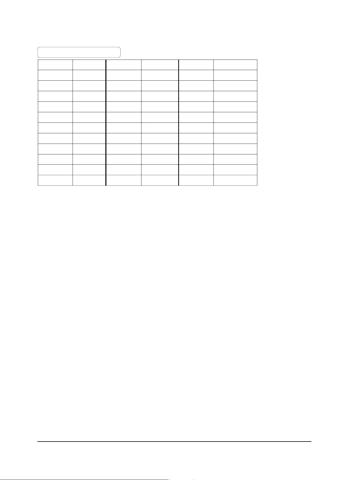
2(CH) PDL 0(FIXED ) TSC 40
AG C 18(F IXE D ) VOL 25(F IXE D ) SA 25(FIX E D)
VC O 80(F IXE D ) PSL 31(FIXE D ) QEW 5
SBT 7 PVS 31 PCT 7(F IXE D )
SCT 16 PVA 31 PTT 31(FIXE D )
SC R 5(FIXED ) PHS 40 PHM 8(F IXE D )
SC 11(F IXE D ) PEW 38 PVP 31(FIX ED )
RG 31 PEP 22 NVP 3 1(FIXE D )
BG 31 PEC 22 PHP 42(FIX E D)
CDL 7(FIXE D) PET 30 NSR 3(F IXE D )
STT 10(FIX E D) VSC 31(F IXE D ) FFI
1:INDIA,0:OTHE RS
OSD
INITIAL OSD
OSD
INITIAL
INITIAL
FACTORY MODE VALUE
Page 4

Alignment and Adjustments
4-4 Samsung Electronics
4-2-4 Option Byte Table
OPTIO N OSD NOT E
SYSTE M
CS MUL TI SYSTEM
CS-CHINA WITHOUT SEC AM SYSTEM
CB/ CII PAL-B/G & PAL- I
CK/ CX PA L / SECAM B/G, D / K
NO R MAL / ZOOM / 1 6:9
SELECT A MODE AVAILABLE TO
AD JUS T P-S IZE
P LU S/ ZOOM
NOR MAL /ZOO
M
PLUS/NORMAL
PLUS /NORMAL/ZOOM/1 6 :9
PIP
ON PIP USE D
OFF PIP DE LE TED
JACK
SC ART 21P IN JAC K USE D
RCA RCA JACK USED
AUDIO
NIC AM NIC AM MODULE USED
STEREO A2 MODULE USED
L-STEREO MONO & LINE STER EO USED
MONO MONO USED
ONE C HIP
TDA8844 CRT (MORE THAN 22-INCH) USED
TDA8842 CRT (MORE THAN 21-INCH) USED
System : cs
Normal / Zoom / 16:9
Pip : on
Jack : RCA
Audio : Nicam
One Chip : TDA8844
Language : English
Text : ON
X-prot : OFF
S-sytem : B/G
Page 5

Alignment and Adjustments
Samsung Electronics 4-5
OPTIO N OSD NO TE
LANGUAGE
ENGLISH ONLY
ARAB ENGLISH / ARABIAN
PERSIAN ENGLISH / PERSIAN
FRANCH ENGLISH / FRENCH
CHINA ENGLISH / CHIN E S E
IN DONE SIA ENGLISH / INDONESIAN
MALAYSIA ENGLISH / MALAYSIAN
THAI ENGLISH / THAI
VIE TNAM ENGLISH / VIE TNAMESE
AR AB /F RANCH E NG LISH / AR AB IAN / F RE N CH
MULTI
ENGLISH / AR ABIAN / PER SIAN / FRENCH
/ CHINESE / INDONE S IAN / MALAYSIA N/ THAI
/VIETNAM
TE XT
ON TTX USED
OFF TTX DE LETE D
X-PR OT
ON X-RAY PROTECTOR USED
OFF NO X-RAY PROTECTOR FUNCTION
S-SYSTEM
B/G
1.THE SOUND SYSTEM C OME S FIRST
IN AUTO S EARCH
2.SOUND SYSTEM IN FAC TORY MODE
RESET
3."AUTO" MODE IS SHOWN ONLY WHEN
L-STER E O OR MONO IS SE LE C TE D IN THE
AUDIO MODE.
I
D/K
M
AU TO
ENGLISH
Page 6

Alignment and Adjustments
4-6 Samsung Electronics
4-3 Other Adjustments
4-3-1 General
1. Usually, a color TV needs only slight touchup adjustment upon installation. Check the
basic characteristics such as height, horizontal
and vertical sync and focus.
2. The picture should have good black and white
details. There should be no objectionable
color shading; if color shading is present, perform the purity and convergence adjustments
described below.
3. Use the specified test equipment or its equivalent.
4. Correct impedance matching is essential.
5. Avoid overload. Excessive signal from a sweep
generator might overload the front-end of the
TV. When inserting signal markers, do not
allow the marker generator to distort test
results.
6. Connect the TV only to an AC power source
with voltage and frequency as specified on the
backcover nameplate.
7. Do not attempt to connect or disconnect any
wires while the TV is turned on. Make sure
that the power cord is disconnected before
replacing any parts.
8. To protect against shock hazard, use an isolation transformer.
4-3-2 Automatic Degaussing
A degaussing coil is mounted around the picture tube, so that external degaussing after
moving the TV should be unnecessary. But
the receiver must be properly degaussed upon
installation.
The degaussing coil operates for about 1 second after the power is switched ON. If the set
has been moved or turned in a different direction, disconnect its AC power for at least 30
minutes.
If the chassis or parts of the cabinet become
magnetized, poor color purity will result. If
this happens, use an external degaussing coil.
Slowly move the degaussing coil around the
faceplate of the picture tube and the sides and
front of the receiver. Slowly withdraw the coil
to a distance of about 6 feet before removing
power.
4-2-5 RESET
The Reset Mode is used during factory inspection.
Function Reset:
1. Channels Add/Erase
2. Language Basic (English)
Page 7

Alignment and Adjustments
Samsung Electronics 4-7
4-3-3 High Voltage Check
CAUTION: There is no high voltage adjustment on this chassis.
The B+ power supply must be set to +130 volts (Full color bar input
and normal picture level).
1. Connect a digital voltmeter to the second
anode of the picture tube.
2. Turn on the TV. Set the Brightness and
Contrast controls to minimum (zero beam current).
3. The high voltage should not exceed 33KV.
4. Adjust the Brightness and contrast controls to
both extremes. Ensure that the high voltage
does not exceed 33KV under any conditions.
4-3-4 FOCUS Adjustment
1. Input a black and white signal.
2. Adjust the tuning control for the clearest
picture.
3. Adjust the FOCUS control for well defined
scanning lines in the center area of the screen.
4-3-5 Screen Adjustment
1. Connect CRT socket pin GK, BK, RK to an
oscilloscope probe.
2. Input a gray scale pattern. (Use a pattern
generator, PM5518)
3. Use the Picture mode for the STANDARD pic-
ture.
4. Adjust the Screen VR (on the FBT) so that the
voltage on the oscilloscope becomes 130+2.5V
(See Fig. 4-1).
4-3-6 Purity Adjustment
1. Warm up the receiver for at least 20 minutes.
2. Plug in the CRT deflection yoke and tighten
the clamp screw.
3. Plug the convergence yoke into the CRT and
set in as shown in Fig. 4-2.
4. Input a black and white signal.
5. Fully demagnetize the receiver by applying an
external degaussing coil.
6. Turn the CONTRAST and BRIGHTNESS controls to maximum.
7. Loosen the clamp screw holding the yoke.
Slide the yoke backward or forward to provide vertical green belt. (Fig. 4-3).
8. Tighten the convergence yoke.
9. Slowly move the deflection yoke forward,
and adjust for the best overall green screen.
10. Temporarily tighten the deflection yoke.
11. Produce blue and red rasters by adjusting the
low-light controls. Check for good purity in
each field.
12. Tighten the deflection yoke.
Fig. 4-1
130 2.5V
+
_
GND
_
Page 8

Alignment and Adjustments
4-8 Samsung Electronics
4-3-7 White Balance Adjustment
Fig. 4-2 Convergence Magnet Assembly
4 Pole Magnet
6 Pole Magnet
2 Pole Magnet
Clamper
Screw
2 POLE
PURITY
YOKE
CLAMP
SCREW
6 POLE
CONVERGENCE
4 POLE
CONVERGENCE
Fig. 4-3 Center Convergence Adjustment
31m/m
Vertical Green Belt
Fig. 4-4
1
2
(a) Set up
1. Warm up the TV for at least 30 minutes in the
White Pattern.
2. Input a Toshiba pattern.
(b) High-Light Adjustment
Set SCT to 50 ± 5 fL in the Factory Service
Mode with using CA100. (See Fig. 4-4 ①)
(c) Low-Light Adjustment
Set SBT to 1.2 ± 0.2 fL in the Factory Service
Mode with using CA100. (See Fig. 4-4 ➁)
Page 9

Alignment and Adjustments
Samsung Electronics 4-9
4-3-8 Center Convergence Adjustment
1. Warm up the receiver for at least 20 minutes.
2. Adjust the two tabs of the 4 pole magnets to
change the angle between them. Superimpose
the red and blue vertical lines in the center
area of the screen.
3. Adjust the Brightness and Contrast controls
for a well defined picture.
4. Adjust the two-tab pairs of the 4 pole magnets, and change the angle between them.
Superimpose the red and the blue vertical
lines in the center area of the screen.
5. Turn the both tabs at the same time, keeping
the angle constant, and superimpose the red
and blue horizontal line in the center of the
screen.
6. Adjust the two-tab pairs of the 6-pole magnets
to superimpose the red and blue line onto the
green. (Changing the angle affects the vertical
lines, and rotating both magnets affects the
horizontal lines.)
7. Repeat adjustments 2~6, if necessary.
8. Since the 4-pole magnets and 6-pole magnets
interact, the dot movement is complex
(Fig. 4-5).
Fig. 4-5 Center Convergence Adjustment
RED
BLUE
BLUE
RED
4-Pole Magnet Movement
GREEN
RED/BLUE
RED/BLUE
GREEN
6-Pole Magnet Movement
4-3-9 RF AGC Adjustment
1. Tune to the strongest local station.
2. Enter the Factory Service Mode to make adjustments.
3. Adjust the AGC control untill noise(snow) disappears from the screen.
Page 10

Alignment and Adjustments
4-10 Samsung Electronics
4-3-10 Geometry Adjustment
1. Inp ut a lion head pattern.
2. Adju s t P VS s o that the pic ture is vertically c entered.
3. Adju s t with PV A so that the top and bottom m a rgin s of the picture a re 4 .
4. Adju st PH S so that the pic ture is horiz ontally centered.
5. Adju s t with PE W s o that the left and righ t m a rgin s of the picture ar e 5.
6. Input a crosshatch pattern.
7. Adjust PEP, PEC , PET for vertical linearity.
4
4
5
5
 Loading...