

DIGITAL TELEVISION RECEIVER
Chassis : KS9B(P)
Model : CS21S8ML6X/XSE
CS21M20ML6XXTT
DIGITAL TELEVISION RECEIVER CONTENTS
Specifications
Alignment and Adjustments
Exploded Views and Parts List
Electrical Parts List
PCB Diagrams
Schematic Diagrams
1.
2.
3.
4.
5.
6.
SERVICE
Manual

ELECTRONICS
©
Samsung Electronics Co., Ltd. Aug. 2004
Printed in Korea
AA82-01979A
This Service Manual is a property of Samsung Electronics Co.,Ltd.
Any unauthorized use of Manual can be punished under applicable
International and/or domestic law.

Specifications
Samsung Electronics 1-1
1. Specifications
Television
System
Channels
Intermediate
Frequency
Power
Antenna
CS
CZ
CW
CB
Band
VHF
UHF
IF Carrier
Frequency
Picture
Sound
Chroma
PAL, SECAM-B/G,I
02 - 12
21 - 69
PAL, SECM -B/G
38.90[MHz]
33.40[MHz]
34.47[MHz]
PAL, SECAM-B/G,I
01 - 13
21 - 69
PAL, SECAM-D/K,K1
38.90[MHz]
32.40[MHz]
34.47[MHz]
PAL, SECAM-B/G,I
02 - 09
13 - 57
PAL-I
38.90[MHz]
32.90[MHz]
34.47[MHz]
PAL, SECAM-B/G,I
02 - 13
14 - 69
NTSC-M
45.75[MHz]
41.25[MHz]
42.18[MHz]
PAL, SECAM-B/G, D/K, I, NT4.43, NT3.58
PAL, SECAM-B/G, D/K, I
PAL, SECAM-B/G, D/K, I, L/L’
PAL, SECAM-B/G
AC100~240V, 50/60Hz / AC160 ~ 300V, 50Hz
VHF, UHF : Telescopic dipole antenna)(75ohm unbalanced type)
System
System

1-2 Samsung Electronics
MEMO

Alignment and Adjustments
Samsung Electronics 2-1
2. Alignment and Adjustments
2-1 General Alignment Instructions
1. Usually, a color TV-VCR needs only slight
touch-up adjustment upon installation. Check
the basic characteristics such as height,
horizontal and vertical sync and focus.
2. Observe the picture for good black and white
details. There should be objectionable color
shading; if color shading is present,
demagnetize, perform purity and convergence
adjustments described below.
3. Use the specified test equipment or its
equivalent.
4. Correct impedance matching is essential.
5. Avoid overload. Excessive signal from a
sweep generator might overload the front-end
of the TV. When inserting signal markers, do
not allow the marker generator to distort test
results.
6. Connect the TV only to an AC power source
with voltage and frequency as specified on the
backcover nameplate.
7. Do not attempt to connect or disconnect any
wires while the TV is turned on. Make sure
that the power cord is disconnected before
replacing any parts.
8. To protect against shock hazard, use an
isolation transformer.
2-2 Automatic Degaussing
A degaussing coil is mounted around the
picture tube, so that external degaussing after
moving the TV should be unnecessary. But
the receiver must be properly degaussed upon
installation.
The degaussing coil operates for about 1
second after the power is switched ON. If the
set is moved or turned in a different direction,
the power should be OFF for at least 10
minutes.
If the chassis or parts of the cabinet become
magnetized, poor color purity will result. If
this happens, use an external degaussing coil.
Slowly move the degaussing coil around the
faceplate of the picture tube and the sides and
front of the receiver. Slowly withdraw the coil
to a distance of about 6 feet before turning
power OFF.
If color shading persists, perform the
following Color purity and Convergence
adjustments.
2-3 High Voltage Check
CAUTION : There is no high voltage adjustment
on this chassis. The B+ power supply should be
+135 volts (with full color- bar input and normal
picture level).
1. Connect a digital voltmeter to the second
anode of the picture tube.
2. Turn on the TV. Set the Brightness and
Contrast controls to minimum (zero beam
current).
3. Adjust the Brightness and contrast controls to
both extremes. Ensure that the high voltage
does not exceed 30 KV under any conditions.
Alignment and Adjustments
2-2 Samsung Electronics
2-4 FOCUS Adjustment
1. Iput a black and white signal.
2. Adjust the tuning control for the clearest picture.
3. Adjust the FOCUS control for well defined scanning lines in the center area of the screen.
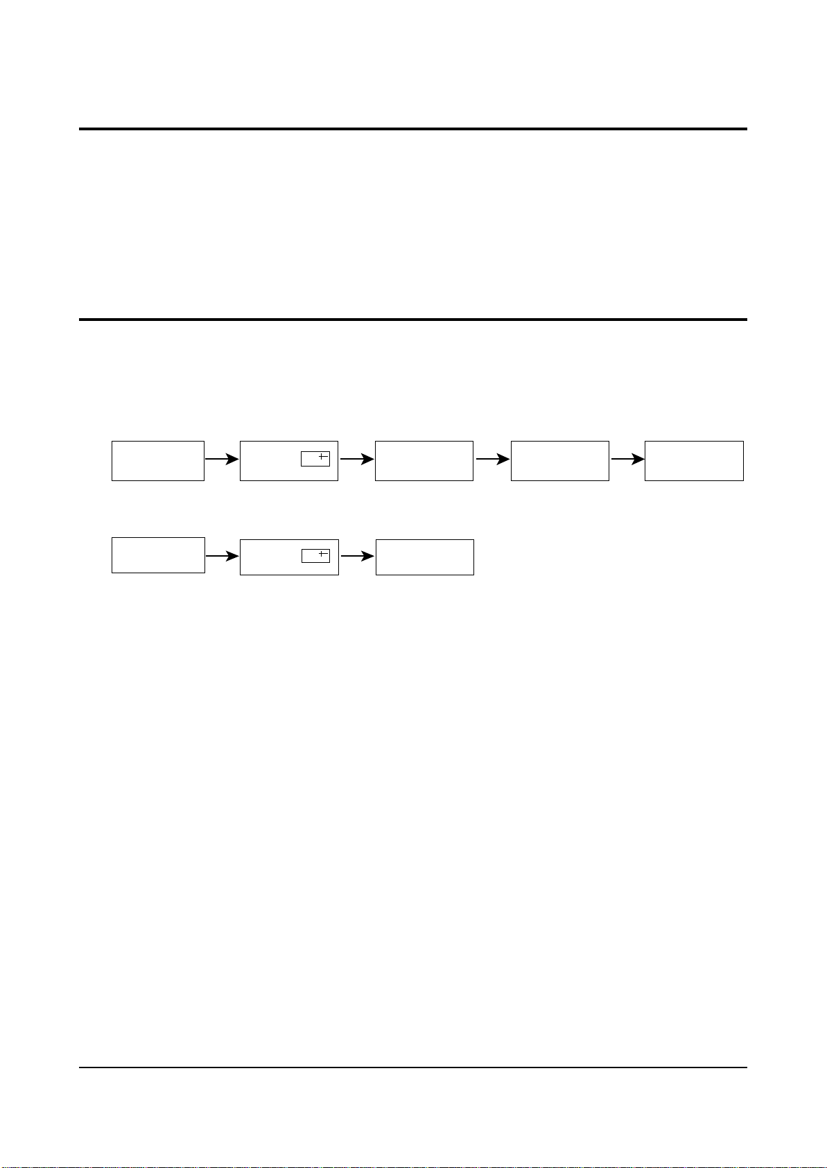
2-5 Factory Adjustment
1. To enter the “Service Mode”, Press the remote-control keys in this sequence :
- If you do not have Factory remote-control
- If you have Factory remote-control
2-5-1 Service Mode
PICTURE OFF PICTURE ON
PICTURE ON
DISPLAY
DISPLAY
()
()
MENU
FACTORY
MUTE
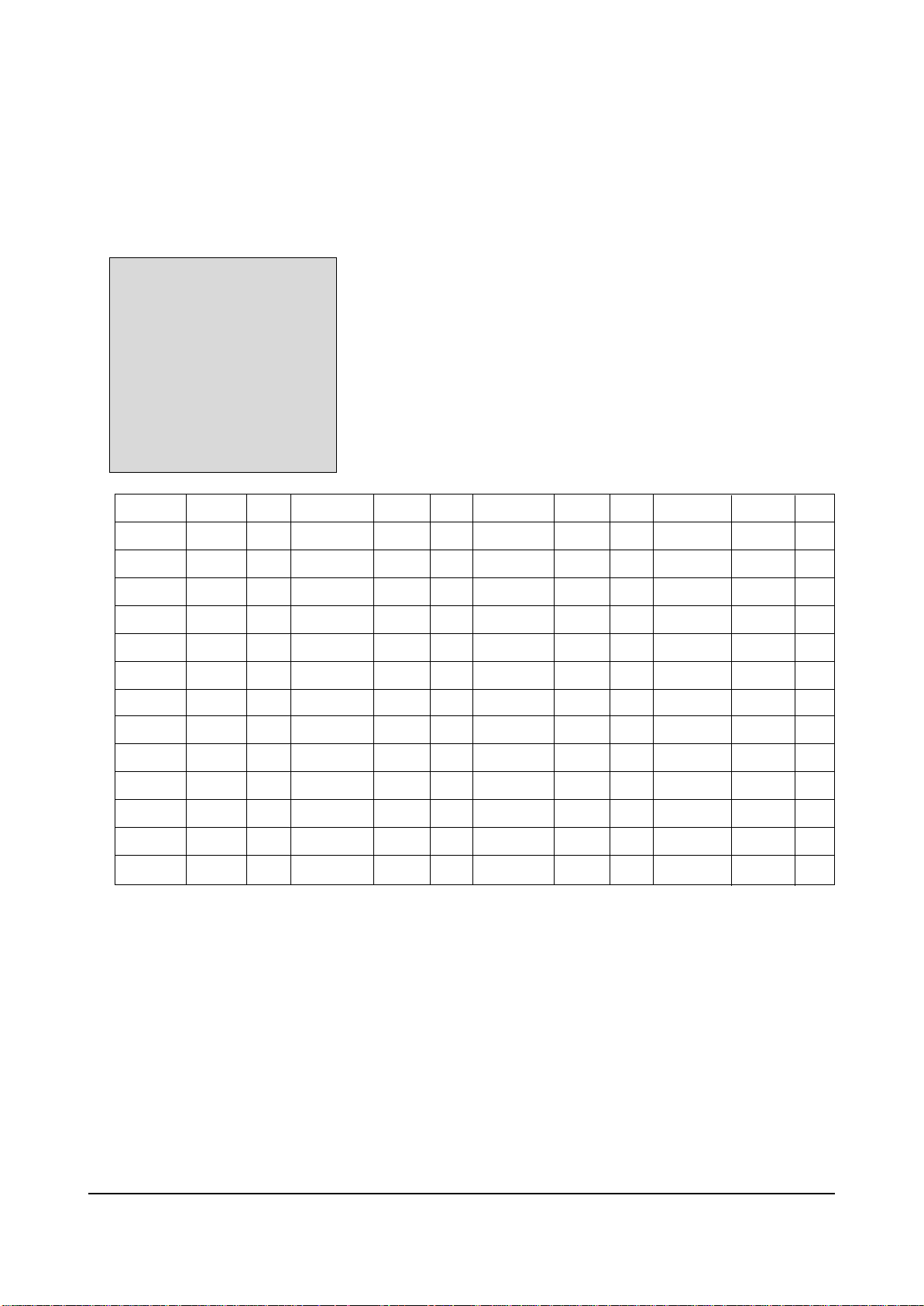
2-5-2 Factoy Mode OSD
ADJUST
OPTION
OPTION1
G2-ADJUST
RESET
SPM-836EE1
AGC
SCT
SBT
BLR
BLB
RG
GG
BG
VSL
VS
VA
HS
SC
CDL
30
13
10
30
30
30
30
30
22
25
43
37
28
13
STT
AKB
PDL
NDL
PSR
NSR
VOL
LCO
TXP
MVOL
FMWS
AGCS1
OMD
SCL
7
0
15
10
15
5
10
0
9
5
0
1
26
1
PWL
AGN
PEK
ACL
FCO
SCBT
TSC
SSP
PSNS
DPSR
DNSR
DCDL
SVM
VMA
12
1
2
0
0
45
40
15
1
15
15
13
0
3
HPAR
HBOW
EWID
EPAR
EUCN
ELCN
ETRP
VZ
FOAB
32
32
32
32
32
32
32
54
0
2-5-2(A) ADJUST
✴ TDA959X
Alignment and Adjustments
Samsung Electronics 2-3
FIX
Adjust
Adjust
Adjust
Adjust
Adjust
FIX
Adjust
FIX
Adjust
Adjust
Adjust
FIX
FIX
FIX
FIX
FIX
FIX
FIX
FIX
FIX
FIX
FIX
FIX
FIX
FIX
FIX
FIX
FIX
FIX
FIX
FIX
FIX
FIX
FIX
FIX
FIX
FIX
FIX
FIX
FIX
FIX
Adjust
Adjust
Adjust
Adjust
Adjust
Adjust
Adjust
FIX
FIX

Alignment and Adjustments
2-4 Samsung Electronics
OSD
AGC
SCT
SBT
BLR
BLB
RG
GG
BG
VSL
VS
VA
HS
SC
CDL
STT
AKB
PDL
NDL
PSR
NSR
VOL
LCO
TXP
MVOL
FMWS
AGCS1
OMD
SCL
PWL
AGN
PEK
ACL
FCO
SCBT
TSC
Range
0 ~ 63
0 ~ 23
0 ~ 23
0 ~ 63
0 ~ 63
0 ~ 63
0 ~ 63
0 ~ 63
0 ~ 63
0 ~ 63
0 ~ 63
0 ~ 63
0 ~ 63
0 ~ 15
0 ~ 7
0 ~ 1
0 ~ 15
0 ~ 15
0 ~ 23
0 ~ 23
0 ~ 63
0 ~ 1
0 ~ 15
0 ~ 50
0 ~ 1
0 ~ 3
0 ~ 63
0 ~ 3
0 ~ 15
0 ~ 1
0 ~ 3
0 ~ 1
0 ~ 1
0 ~ 63
0 ~ 23
Register
1Eh(D5-D0)
1Dh
1Bh
14h(D5-D0)
15h(D5-D0)
16h(D5-D0)
17h(D5-D0)
18h(D5-D0)
0Fh(D5-D0)
12h(D5-D0)
10h(D5-D0)
09h(D5-D0)
0Fh(D5-D0)
2Ah(D3-D0)
08h
2Ah(D4)
1Ah(D3-D0)
1Ah(D3-D0)
1Ch
1Ch
1Fh
27h(D7-D5)
87F2h(D5-D0)
Oh(D15-D0)
29h(D5)
28h(D2-D1)
05h(D5-D0)
04h(D5-D4)
04h(D3-D0)
29h(D7)
19h(D7-D6)
20h(D1)
21h(D0)
1Bh
19h(D5-D0)
Initial Value
30
13
10
30
30
30
30
30
22
25
43
37
28
13
7
0
15
10
15
5
10
0
9
5
0
1
26
1
12
1
2
0
0
40
40
Remark
RF AGC
Sub contrast(high light adjustment)
Sub brightness(low light adjustment)
Black level offset R(low light R adjustment)
Black level offset B(low light B adjustment)
White point R(high light R adjustment)
White point G(high light 25 fixed)
White point B(high light B adjustment)
Vertical slope
Vertical shift
Vertical amplitude
Horizontal shift
S-correction
Cathode drive level
Sub tint(NTSC only)
Black current stabilization
PAL Y-delay adjustment
NTSC Y-delay adjustment
PAL sub color gain adjustment
NTSC sub color gain adjustment
Initial vol adjustment
PLL demodulator frequency adjust( 0 : set )
TTX horizontal shift adjustment(Micom Memory Part)
Melody initial vol adjustment(MSP34XX)
Narrow-band sound PLL window selection
IF AGC speed
Off-set IF demodulator
Soft clipping level
Peak white limiting
FM demodulator gain
Peaking center frequency
Automatic color limiting
Forced color limiting
Screen brightness(different from INCH)
Sub Sharpness gain adjustment

Alignment and Adjustments
Samsung Electronics 2-5
OSD
SSP
PSNS
DPSR
DNSR
DCDL
SVM
VMA
HPAR
HBOW
EWID
EPAR
EUCN
ELCN
ETRP
VZ
FOAB
Range
0 ~ 23
0 ~ 1
0 ~ 63
0 ~ 63
0 ~ 63
0 ~ 63
0 ~ 63
0 ~ 63
0 ~ 63
0 ~ 3
0 ~ 3
0 ~ 23
0 ~ 23
0 ~ 23
0 ~ 15
0 ~ 63
Register
21h(D2)
06h(D5-D0)
07(D5-D0)
0Ah(D5-D0)
0Bh(D5-D0)
0Ch(D5-D0)
0Dh(D5-D0)
0Eh(D5-D0)
13h(D5-D0)
2Dh(D5-D0)
2Eh(D5-D0)
1Ch
1Ch
1Bh
2Ah(D3-D5)
14h(D5-D0)
Initial Value
15
1
15
10
13
0
3
32
32
32
32
32
32
32
54
0
Remark
Ident sensitivity PAL/NTSC decoder
Horizontal parallelogram
Horizontal bow
EW width
EW parabola
EW upper corner parabola
EW lower corner parabola
EW tarpezium
Vertical zoom
Delay of RGB output to VM output
Ampulitude of SVM out
DVD PAL sub color gain adjustment
DVD NTSC sub color gain adjustment
DVD Sub brightness(low light adjustment)
DVD Cathode drive level
DVD Black level offset R(low light R adjustment)
Alignment and Adjustments
2-6 Samsung Electronics
ADJUST
OPTION xx xx xx
G2-ADJUST
RESET
SPM-836EE1
Item
LNA
SYSTEM
AUDIO
EQUALIZER
JACK
AV ZOOM
AUTO POWER
EW
AUTO FM
HOTEL MODE
BL STRETCH
HIGH DEVLA
HELP MENU
LIST/FLOF
TIME
V-GUARD
TILT
DOLBY
No
1
2
3
4
5
6
7
8
9
10
11
12
13
14
15
16
17
18
Initial value
ON
CS
STEREO
ON
SCART
NOR/ZOOM/16:9
ON
ON
ON
OFF
ON
OFF
ON
FLOF
ON
OFF
OFF
OFF
Remarks
CIS : ON , OTHER : OFF
L-STEREO/STEREO
/NICAM
FIX : ON
RCA/SCART/RCA+DVD
FIX
FIX : ON
FIX : ON
FIX : ON
OPTION
FIX : ON
OPTION
OPTION
FIX : ON
OPTION
FIX : OFF
FIX : OFF
FIX : OFF
2-5-2(B) OPTION
ADJUST
OPTION xx xx xx
G2-ADJUST
RESET
SPM-836EE1
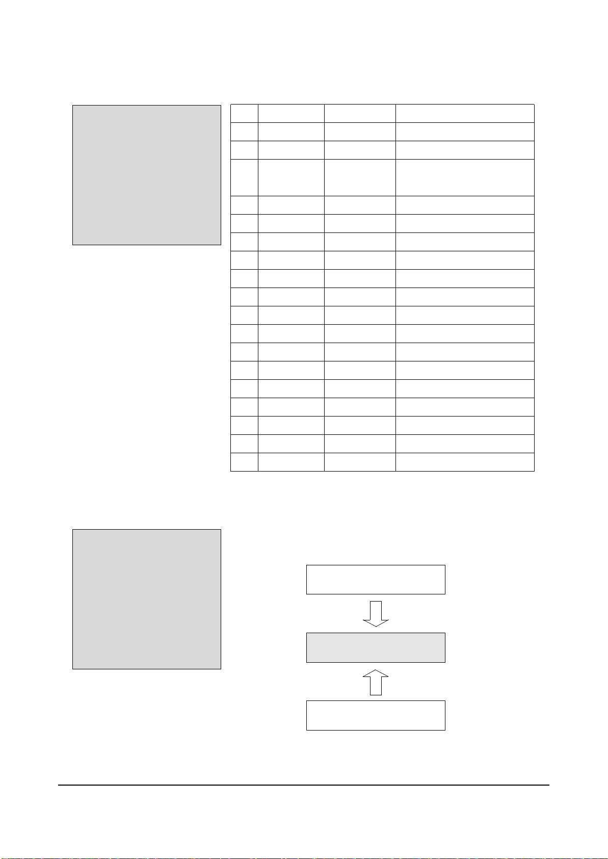
2-5-2(C) G2-ADJUST
☞ Entering G2-Adjust Mode Screen Adjust : Displyed As “NG”.
→ Turn SCREEN VR OF FBT, Adjust Value Become To Be “OK”.
Screen Adjust : N.G
Screen Adjust : O.K
Screen Adjust : N.G
Alignment and Adjustments
Samsung Electronics 2-7
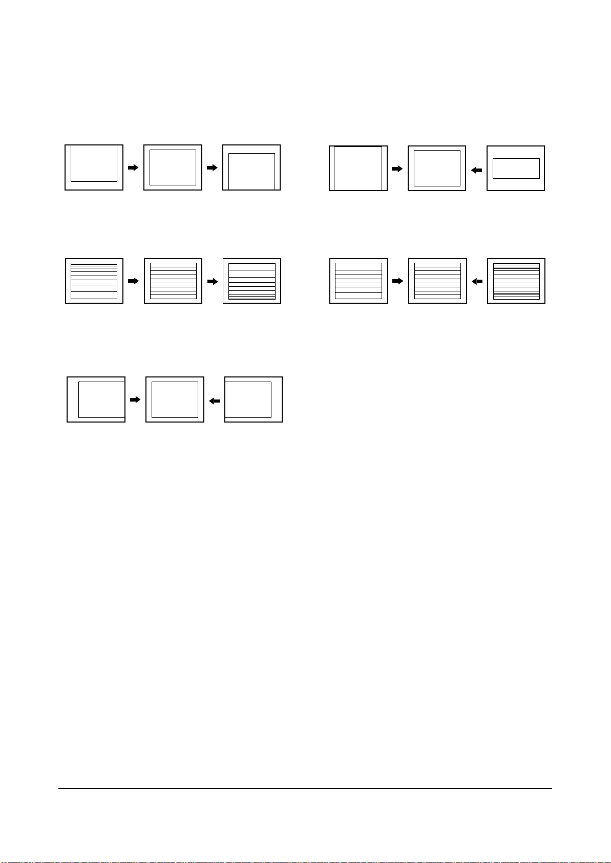
2-5-2(D) SCREEN CHANGE (I2C BUS GEOMETRIC ADJUSTMENT)
1 V Shift
2 V Amp
3
5
V Slope
H Shift
V SC
4

Alignment and Adjustments
2-8 Samsung Electronics
PIN NO
1
2
3
4
5
6
7
8
9
10
11
12
13
14
15
16
17
18
19
20
21
22
23
24
25
26
27
28
29
30
31
32
SYMBOL
P1.3/T1
P1.6/SCL
P1.7/SDA
P2.0/TPMW
P3.0/ADC0
P3.1/ADC1
P3.2/ADC2
P3.3/ADC3
VSSC/P
P0.5
P0.6
VSSA
SECPLL
VP2
DECDIG
PH2LF
PH1LF
GND3
DECBG
EWD
VDRB
VDRA
IFIN1
IFIN2
IREF
VSC
AGCOUT
SIFIN1/DVBIN1
SIFIN2/DVBIN2
GND2
SIFAGC/DVBAGCR
REFO/AMOUT/REFIN
PIN FUNCTION
port 1.3 or Counter/Timer 1 input
port 1.6 or IIC-bus clock line
port 1.7 or IIC-bus data line
port 2.0 or Tuning PWM output
port 3.0 or ADC0 input
port 3.1 or ADC1 input
port 3.2 or ADC2 input
port 3.3 or ADC3 input
digital ground for m-Controller core and periphery
port 0.5(8mA current sinking capability for direct drive of LEDs)
port 0.6(8mA current sinking capability for direct drive of LEDs)
digital ground of TV-processor
SECAM PLL decoupling
2nd supply voltage TV-processor(+8V)
supply voltage decoupling of digital circuit of TV-processor
phase-2 filter
phase-1 filter
ground 3 for TV-processor
bandgap decoupling
East-West drive output
vertical drive B output
vertical drive A output
IF input 1
IF input 2
reference current input
vertical sawtooth capacitor
tuner AGC output
SIF input 1 / DVB input 1
SIF input 2 / DVB input 2
ground 2 for TV processor
narrow band PLL filter
Automatic Volume Leveling/subcarr reference output/sound IF
input/external reference signal input for I signal mixer for DVB
operation
2-6 PIN ASSIGNMENT SPECIFICATION
CHECK VOLTAGE
S-By P-On

Alignment and Adjustments
Samsung Electronics 2-9
PIN NO
33
34
35
36
37
38
39
40
41
42
43
44
45
46
47
48
49
50
51
52
53
54
55
56
57
58
59
60
61
62
63
64
SYMBOL
HOUT
FBISO
QSSO/AMOUT
EHTO
PLLIF
IFVO/SVO/DVBO
VP1
CVBS1
GND
CVBS/Y
C
SVM
INSSW2
R2/VIN
G2/YIN
B2/UIN
BCLIN
BLKIN
RO
GO
BO
VDDA
VPE
VDDC
OSCGND
XTLIN
XTLOUT
RESET
VDDP
P1.0/INT1
P1.1/T0
P1.2/INTO
PIN FUNCTION
horizontal output
flyback input/sandcastle output
QSS intercarrier output/AM output in stereo applications or
deemphasis(front-end audio out)/AM output in mono applications
EHT/overvoltage protection input
IF-PLL loop filter
AGC sound IF/inter-external AGC for DVB applications
main supply voltage TV processor
internal CVBS input
ground for TV processor
CVBS3/Y input
chroma input
scan velocity modulation output
2nd RGB/YUV insertion input
2nd R input/V(R-Y) input PR input
2nd G input/Y input
2nd B input/U(B-Y) input PB input
beam current limiter input
black current input/V-guard input
Red output
Green output
Blue output
analog supply of Teletext decoder and digital supply of TVprocessor(3.3 V)
OTP Progamming Voltage
digital supply to core(3.3 V)
oscillator ground supply
crystal oscillator input
crystal oscillator output
reset
digital supply to peryipher(+3.3 V)
port 1.0 or external interrupt 1 input
port 1.1 or Counter/Timer 0 input
port 1.2 or external interrupt 0 input
CHECK VOLTAGE
S-By P-On

Alignment and Adjustments
2-10 Samsung Electronics
2-7 Main Adjustment Parameter(TDA 93XX)
✴ TDA93XX(IC201S)
NOTE : PVS,PVA, PHS, parameters must be aligned using the 50Hz vertical-field rates.
OSD FUNCTION RANGE INITIAL DATA REMARK
AGC
SCT
SBT
BLR
BLB
RG
GG
BG
VSL
VS
VA
HS
SC
CDL
STT
AKB
PDL
NDL
PSR
NSR
VOL
LCD
TXP
MVOL
FMWS
AGCS
OMD
SCL
PWL
AGN
PEK
ACL
FCO
SCBT
TSC
SSP
PSNS
Automatic Gain Control
Sub Contrast
Sub Brightness
Black Level offset Red
Black Level offset Blue
Red Gain
Green Gain
Blue Gain
Vertical Slope
Vertical Shift
Vertical Amplitude
Horizontal Shift
S-Correction
Cathode Drive Level
Sub Tint
Black Current Stabilisation
PAL Delay
NTSC Delay
PAL Sub Color
NTSC Sub color
Volume pre setting
SECAM-L Vision IF
TTX Position
Melody Volume Levle
Window Selection of Narrow SoundPLL
IF AGC Speed
Off-set IF Demodulator
Soft Clipping Levle
Peak White Limiting
Gain FM Demodulator
Peaking Centre Frequency
Automatic Color Limiting
Forced Color On
Screen Adjust Bright Value
TTX Mix Mode Sub Contrast
Ident Sensitivity PAL/NTSC decoder
Horizontal parallelogram.
0 ~ 63
0 ~ 23
0 ~ 23
0 ~ 63
0 ~ 63
0 ~ 63
0 ~ 63
0 ~ 63
0 ~ 63
0 ~ 63
0 ~ 63
0 ~ 63
0 ~ 63
0 ~ 15
0 ~ 7
0 ~ 1
0 ~ 15
0 ~ 15
0 ~ 23
0 ~ 23
0 ~ 63
0 ~ 1
0 ~ 15
0 ~ 50
0 ~ 1
0 ~ 3
0 ~ 63
0 ~ 3
0 ~ 15
0 ~ 1
0 ~ 3
0 ~ 1
0 ~ 1
0 ~ 63
0 ~ 63
0 ~ 23
0 ~ 1
30
13
9
31
27
32
32(Fix)
31
30
35
42(Fix)
30
28(Fix)
9
7(Fix)
0(Fix)
1(Fix)
10(Fix)
10(Fix)
10(Fix)
10(Fix)
Option
9(Fix)
10(Fix)
0(Fix)
1
26(Fix)
1(Fix)
12(Fix)
1(Fix)
2(Fix)
1(Fix)
0(Fix)
45(Fix)
20(Fix)
20(Fix)
1(Fix)
CF MODEL : 1, others : 0
CF MODEL : 0, others : 1
TTX Option

Alignment and Adjustments
Samsung Electronics 2-11
2-8 Option Bytes(TDA 93XX)
In the Service Mode, various can be selected via the Option Table. Example:
TDA93XX (IC201S)
✴
SPM-802XX REMARK
1
LNA
ON/OFF
CIS : ON Others : OFF
2
3
4
5
6
7
8
9
10
11
12
13
14
15
TDA93XX/TDA959X PIN Diffrence
✴
IC ver sion
East-W est Y/N N Y N Y
Pin 20 AVL EWD AVL EWD
Pin 28 AUDEEM SIFIN1
Pin 29 DECSDEM SIFIN2
Pin 31 SNDPLL SIF AGC
Pin 32 SNDIF
Pin 35 AUDEXT AUDEXT QSSO AMOUT AUDEXT QSSO AMOUT
Pin 44 AUDOUT controlled AM or audio out
SYSTEM
AUDIO
JACK
ZOOM
AUTO POWER
AUTO FM
2ND SIF
HOTEL MODE
BKS
HIGH DEVIA
HELP MENU
LIST/FLOF
TIME
V-GUARD
MONO/L-STEREO/STEREO/NICAM
FM-PLL ver sion
REFO AVL/SNDIF REFO AMOUT REFO AMOUT REFO
CS/CZ/CF/CB/CI
RCA/SCART
NOR/ZOOM/16"9
ON/OFF
ON/OFF
ON/OFF
ON/OFF
ON/OFF
ON/OFF
ON/OFF
FLOF/LIST
ON/OFF
ON/OFF
(TDA93XX)
OPTION
OPTION
OPTION
FIX : NOR/ZOOM
FIX : ON
FIX : ON
OPTION
OPTION
FIX : ON
OPTION
FIX : ON
OPTION
OPTION
FIX : OFF
QSS ver sion
(TDA959X)

2-12 Samsung Electronics
MEMO

3. Exploded View & Parts List
3-1 CS21S8ML6X/XSE
Exploded View & Parts List
Samsung Electronics 3-1
T0607 AA61-40113A STOPPER-PCB;501H,HIPS,-,-,HB,NTR,- 1 S.N.A
CCM1 AA60-10050R SCREW-MACHINE;-,SWRCH18A,M5,L31.5,HH,+,W 4 S.N.A
CIS7 AA61-60003J SPRING ETC-CS;-,SUS304,-,-,OD6,N7,OD6,-, 1 S.N.A
T0003 AA64-02232P CABINET FRONT;21S8,KS9B(G/R),ASIA,HIPS,H 1 S.N.A
T0023 AA64-02235B KNOB POWER;21S8,ABS,HB,G3676,GDM3130 1 S.N.A
T0022 AA64-02236B KNOB CONTROL;21S8,ABS,HB,G3676,GDM3130 1 S.N.A
T0299 AA64-02237A WINDOW-RMC,LED;21S8,ACRYL,CLR 1 S.N.A
T0201 AA64-02239C DECORATION-TWEETER,L;21S8 NEW,HIPS,HB,G4 1 S.N.A
T0200 AA64-02239D DECORATION-TWEETER,R;21S8 NEW,HIPS,HB,G4 1 S.N.A
T0057 AA64-70123A BADGE-BRAND;NEW,AL,L50,FLAT,SILVER,SAMSU 1 S.N.A
T0010 AA91-00922B ASSY HOLDER SPK;-,-,4OHM/15W,-,COLOR CH' 2 S.N.A
T0010 AA91-00862A ASSY HOLDER SPK;-,-,4OHM,-,Áß³²¹Ì SOUND 1 S.N.A
T0010 AA91-00861A ASSY HOLDER SPK;-,PP,8OHM,-,MIDDLE AMERI 1 S.N.A
T0015 AA64-02233A CABINET-BACK;21S8,HIPS,HB,G4309 1
T0063 AA03-00403A CRT COLOR;A51QDX993X,0MG,1.75MH,18MH,3.1 1
T0527 AA65-00009B CLAMPER CORE-D,COIL;21A8,NYLON 66,V0,-,- 4 S.N.A
M0014 AA94-14362T ASSY PCB MAIN;CS21S8ML6X/XSE,GOLD RUSH 2 1
T0296 AA94-13031A ASSY PCB MISC-FRONT A/V;21A8,B-LOT 1
T0066 AA96-20109C ASSY POWER CORD;-,CP2/NO(4.0),H/C300,KKP 1 S.N.A
T0074 AA59-00312C REMOCON;DEEP IMPACT,TM75,35,NON-TTX,EX,P 1
No Code No Description Specification Q’ty S.N.A
You can search for the updated part code through ITSELF web site.
URL : http://itself.sec.samsung.co.kr

Exploded View & Parts List
3-2 Samsung Electronics
3-2 CS21M20ML6XXTT
T0175 AA96-01572A ASSY SPEAKER P;8ohm,semidome,10W,AA91-00 1
T0245 AA61-00711D HOLDER-PCB;29U1,U2,HIPS VO,BK502(HB-PROP 2 S.N.A
CIS7 AA61-60003J SPRING ETC-CS;-,SUS304,-,-,OD6,N7,OD6,-, 1 S.N.A
T0022 AA64-03859A KNOB CONTROL;29M20,ABS,HB,G3676,SVM3012 1 S.N.A
T0023 AA64-03860A KNOB POWER;29M20,ABS,HB,G3676,SVM3012 1 S.N.A
T0299 AA64-03861A WINDOW-RMC LED;29M20,PC,CLEAR 1 S.N.A
CIS3 AA64-03862A DECORATION-POWER;29M20,ABS,HB,G3676,AL 1 S.N.A
T0003 AA64-03863C CABINET FRONT;21M20,TTSEC,HQ,HIPS,HB,G43 1 S.N.A
T0057 AA64-70123A BADGE-BRAND;NEW,AL,L50,FLAT,SILVER,SAMSU 1 S.N.A
T0015 AA64-02331A CABINET-BACK;21M6,HIPS,V0,G4309 1
T0066 AA96-20120C ASSY POWER CORD;-,EP2/NO(CHI),H/C300,RVV 1 S.N.A
T0063 AA03-00403A CRT COLOR;A51QDX993X,0MG,1.75MH,18MH,3.1 1
T0527 AA65-00009B CLAMPER CORE-D,COIL;21A8,NYLON 66,V0,-,- 4 S.N.A
M0014 AA94-14364A ASSY PCB MAIN;CS21M20ML6XXTT,GOLD RUSH 2 1
T0098 AA94-14567A ASSY PCB MISC-CONTROL;21M20,KS9B China 1 S.N.A
T0091 AA95-03194A ASSY SUB PCB-SIDE A/V;S56A,B-LOT 1
T0074 AA59-00312E REMOCON;Deep Impact,TM75,36,PAL,EX,PAL,S 1
No Code No Description Specification Q’ty S.N.A
You can search for the updated part code through ITSELF web site.
URL : http://itself.sec.samsung.co.kr

Electrical Parts List
Samsung Electronics 4-1
ASSY COVER FRONT
1 M0001 AA90-04993M ASSY COVER FRONT;CS21M20ML6XXTT S.N.A
..2 T0081 6003-001026 SCREW-TAPTITE;RH,+,B,M4,L15,ZPC(BLK),SWR S.N.A
..2 T0081 6003-001026 SCREW-TAPTITE;RH,+,B,M4,L15,ZPC(BLK),SWR S.N.A
..2 T0081 6003-001026 SCREW-TAPTITE;RH,+,B,M4,L15,ZPC(BLK),SWR S.N.A
..2 T0081 6003-001268 SCREW-TAPTITE;TH,+,B,M4,L12,ZPC(YEL),SWR S.N.A
..2 T0081 AA60-10002A SCREW-TAPPING;-,ZPC(YEL),M4,L12,RH,+,-,- S.N.A
..2 CCM1 AA60-10050R SCREW-MACHINE;-,SWRCH18A,M5,L31.5,HH,+,W S.N.A
..2 T0081 AA60-10050T SCREW-TAPPING;-,SWRCH18A,M4,L20,RH,+,2S, S.N.A
..2 T0175 AA96-01572A ASSY SPEAKER P;8ohm,semidome,10W,AA91-00
..2 M0003 AA96-02057F ASSY COVER P-FRONT;21M20,TTSEC,HIPS,HB,G
...3 T0081 6003-001019 SCREW-TAPTITE;RH,+,B,M4,L12,ZPC(BLK),SWR S.N.A
...3 T0081 6003-001019 SCREW-TAPTITE;RH,+,B,M4,L12,ZPC(BLK),SWR S.N.A
...3 T0069 AA60-00091G SPACER-FELT;-,FELT,200X10,-,-,BLK,T0.5,- S.N.A
...3 T0069 AA60-00091R SPACER-FELT;,FELT,250X10,,,BLK,T0.5,, S.N.A
...3 T0245 AA61-00711D HOLDER-PCB;29U1,U2,HIPS VO,BK502(HB-PROP S.N.A
...3 CIS7 AA61-60003J SPRING ETC-CS;-,SUS304,-,-,OD6,N7,OD6,-, S.N.A
...3 T0578 AA64-03660P INLAYAV;21M16,KS9B,PS,T0.3,SHEET,BLK,SI S.N.A
...3 T0022 AA64-03859A KNOB CONTROL;29M20,ABS,HB,G3676,SVM3012 S.N.A
...3 T0023 AA64-03860A KNOB POWER;29M20,ABS,HB,G3676,SVM3012 S.N.A
...3 T0299 AA64-03861A WINDOW-RMC LED;29M20,PC,CLEAR S.N.A
...3 CIS3 AA64-03862A DECORATION-POWER;29M20,ABS,HB,G3676,AL S.N.A
...3 T0003 AA64-03863C CABINET FRONT;21M20,TTSEC,HQ,HIPS,HB,G43 S.N.A
...3 T0057 AA64-70123A BADGE-BRAND;NEW,AL,L50,FLAT,SILVER,SAMSU S.N.A
...3 AA65-00011C CLAMPER CORE-WIRE;ALL MODEL,NYLON 66,V2, S.N.A
...3 AA65-30105A CLAMPER CORE-WIRE;ALL MODEL,NYLON 66,V2, S.N.A
...3 T0382 BP61-00509C HOLDER-CARE;PJT,ACRYL-FOAM,T0.25,W20.0mm S.N.A
..2 T0382 BP61-00495C HOLDER-CARE;PJT,ACRYL-FOAM,T0.25,W30.0mm S.N.A
ASSY COVER REAR
1 M0002 AA90-04994J ASSY COVER REAR;21M20,HQ,TT(330),HIPS,V0 S.N.A
..2 T0069 AA60-00091J SPACER-FELT;-,FELT,330X10,-,-,BLK,T0.5,- S.N.A
..2 AA64-00892T INLAY-BACK;D2,D3 CHINA,PS SHEET,T0.3,BLK S.N.A
..2 T0015 AA64-02331A CABINET-BACK;21M6,HIPS,V0,G4309
..2 T0214 AA65-30008A CLAMPER CORE-CORD;-,PE,HB,-,BLK,- S.N.A
ASSY CPT
1 T0521 AA91-07326S ASSY CPT;A51QDX993X,0MG,21,SDI,MST S.N.A
..2 T0063 AA03-00403A CRT COLOR;A51QDX993X,0MG,1.75MH,18MH,3.1
..2 T0079 AA27-00002A MAGNET CONVERGENCE;JH291-11D,29.1MM
..2 T0089 AA27-00256A COIL DEGAUSSING;,21IHCH,10%,35TS,4.5OHM,
..2 AA63-60028A SPACER-DY;-,NEOPRENE,-,-,-,BLK,-,-,V0 W1 S.N.A
..2 T0527 AA65-00009B CLAMPER CORE-D,COIL;21A8,NYLON 66,V0,-,- S.N.A
..2 AA98-70014C ASSY TBC WIRE P;TVI,21,NTSC,1P,UL1015#22 S.N.A
..2 T0078 AA27-00324A DEFLECTION YOKE;,DIF-2192AA(A),S/T,A51QD
ASSY FIXING
1 AA91-08006K ASSY FIXING;GOLD RUSH,CHINA,CP2/NO,KS9B S.N.A
..2 T0245 AA39-20010B LEAD CONNECTOR-ASSY;,1P,500,YFH800-01,S,
..2 AA65-30009A CLAMPER CORE-FBT;-,ABS,V0,-,BLK,- S.N.A
..2 AA65-30018A CLAMPER CORE-WIRE;DONG-A,NYLON-66,-,-,-, S.N.A
..2 AA65-30111A CLAMPER CORE-WIRE;ALL MODEL,NYLON,V0,-,W S.N.A
..2 T0066 AA96-20120C ASSY POWER CORD;-,EP2/NO(CHI),H/C300,RVV S.N.A
...3 3811-001609 WIRE-PVC CU;BCWA,300V,ROLL,-,#22,BLK S.N.A
...3 T0268 AA39-10007T CBF-POWER CORD;-,RVVZ-2P,RVVB 2x0.75mm,2
...3 AA61-20284A HOLDER;P-CORD,PP,-,-,-,BLK,VO,KE-002 S.N.A
..2 T0245 AA39-20179A LEAD CONNECTOR-ASSY;,3(2)P,300MM,YFH800-
ASSY CHASSIS
1 M0017 AA91-08021A ASSY CHASSIS;CS21M20ML6XXTT,GOLD RUSH 2, S.N.A
..2 T0569 AA94-14275A ASSY PCB MISC-MASTER;21M20,FULL-MONTY,KS S.N.A
...3 0202-001366 SOLDER-WIRE FLUX;-,RS60S,D1.2,63Sn/37Pb, S.N.A
...3 CN906 3711-004696 CONNECTOR-HEADER;NOWALL,3P,1R,5MM,ANGLE,
...3 CN906 3711-004697 CONNECTOR-HEADER;NOWALL,3P,1R,5MM,ANGLE,
...3 T0081 6003-000333 SCREW-TAPTITE;RH,+,2S,M3,L10,ZPC(YEL),SW S.N.A
...3 T0062 AA61-01376A HOLDER-POWER;HIPS V0,29M20,BLK S.N.A
...3 AA97-14856A ASSY AUTO-PCB;CS21M20MQZXBWT,FULLMONTY S.N.A
....4 AA41-01056A PCB SUB-MASTER S/W;CS21M20MQ,FR-1,1,A,24 S.N.A
...3 SW811S 3403-001107 SWITCH-PUSH;250V,5A,DPST,-,KDC-A04
..2 M0014 AA94-14364A ASSY PCB MAIN;CS21M20ML6XXTT,GOLD RUSH 2
...3 0202-001366 SOLDER-WIRE FLUX;-,RS60S,D1.2,63Sn/37Pb, S.N.A
...3 T0083 0402-001477 DIODE-BRIDGE;GSIB460,600V,4A,SIP-4,ST
...3 T0083 0402-001599 DIODE-RECTIFIER;DGP30L,1500,3A,DO-201AD(
...3 T0090 0502-001268 TR-POWER;FJAF6806D,NPN,50000mW,TP-3PF,ST
...3 PC801S 0604-001032 PHOTO-COUPLER;TR,170-260%,300mW,DIP-4,ST
...3 IC106 1001-000199 IC-VIDEO SWITCH;NJM2246D,3-INPUT,DIP,8P,
...3 IC112 1103-001106 IC-EEPROM;24C080,1Kx8Bit,DIP,8P,9.6x6.4m
...3 T0900 1404-001045 THERMISTOR-NTC;4.7ohm,15%,2900K,35.0mW,T
...3 P803T 1404-001265 THERMISTOR-PTC;4.5OHM/100OHM,+30/-20%,22
...3 C598 2201-000406 C-CERAMIC,DISC;0.27NF,10%,2KV,Y5P,TP,6.3
...3 C598 2201-000446 C-CERAMIC,DISC;3.3NF,20%,400V,Y5U,BK,15X
...3 CR402S 2303-000282 C-FILM,LEAD-PPF;6nF,5%,1.6KV,TP,29*23*8.
...3 CX801S 2306-000318 C-FILM,LEAD-PPF;220NF,20%,250V,BK,-,22.5
...3 CX802S 2306-000318 C-FILM,LEAD-PPF;220NF,20%,250V,BK,-,22.5
...3 CR406S 2306-000350 C-FILM,LEAD-PPF;270NF,5%,400V,BK,26X18.5
...3 C701 2401-000262 C-AL;100uF,20%,160V,HR,TP,16x25,7.5
...3 C701 2401-003339 C-AL;220uF,20%,400V,GP,BK,30x35,10
...3 X201 2801-004033 CRYSTAL-UNIT;12MHZ,30PPM,28-AAM,30PF,30O
...3 SF102S 2904-001143 FILTER-SAW AV;38.9MHz,SIP5K,ST,18dB,B/G,
...3 SF101S 2904-001195 FILTER-SAW AV;38.9MHz,SIP5K,ST,17.9dB,B/
...3 FP801S 3601-000281 FUSE-CARTRIDGE;250V,4A,TIME-LAG,GLASS,5.
...3 V999S 3704-001105 SOCKET-CRT;11P,20PI,26.5PI,NI,...3 CN906 3711-003043 CONNECTOR-HEADER;BOX,4P,1R,2.5MM,STRAIGH
...3 JA701 3722-001333 JACK-PIN;9P,3.2mm,NI,BLK,...3 JA702 3722-001596 JACK-PIN;3P/9P,3.5mm,NI,BLK(GRN/BLU/RED)
...3 T0119 AA09-00406A IC MICOM;TDA9592PS/N1/3I,SPM-836EAN1,64P
...3 IC063 AA13-20004WIC HYBRID;-,PAP103T,SIP,6P,PRE-AMP,TP
...3 T801S AA26-00043A TRANS SWITCHING;-,-,-,AC90~260V,125/12.5
...3 T0616 AA26-00201A TRANS FBT;FCA173B,KS1A-1,3.8mH,FERRITE,1
...3 T401 AA26-50001B TRANS-HORIZ.DRIVE;-,-,-,7.1mH,-,-,102uH,
...3 L403 AA27-00296A COIL CHOKE;220UH,CPTTV,220UH,10%,3A,DR14
...3 T0296 AA27-30003L COIL LINEARITY;-,73uH,DR12x15,0.55mm,-,B
...3 LX801S AA29-30001D FILTER LINE NOISE;SQ1913,-,6.0MH,0.8A,...3 T0245 AA39-20604A LEAD CONNECTOR-ASSY;,UL1007#26,UL/CSA,9/
...3 TU01S AA40-00076A TUNER;TECC0949PG35A(S),PAL,181CH,38.9MHZ
...3 GT301 AA60-40012D PIN-GT,ASSY;T1.6,6-12.5-,NYLON66 S.N.A
...3 IC301 AA96-00623F ASSY HEAT SINK P;LA78045,SCREW,AA62-0005 S.N.A
....4 CIS 0205-001154 OIL-SILICON;G746,-,- S.N.A
....4 T0088 1204-002183 IC-VERTICAL PROCESSO;LA78045,TO220,7P,15
....4 T0081 6003-000334 SCREW-TAPTITE;RH,+,2S,M3,L6,ZPC(YEL),SWR S.N.A
....4 CIS AA62-00056A HEAT SINK-PS;-,-,T1.0,-,41*35*70,D2,-,-, S.N.A
...3 IC501 AA96-50311A ASSY HEAT SINK P;-,VIDEO,AA62-30175D,TDA S.N.A
....4 T0074 1201-001159 IC-VIDEO AMP;6107,ZSIP,9P,-,SINGLE,-,PLA
....4 T0081 6003-000334 SCREW-TAPTITE;RH,+,2S,M3,L6,ZPC(YEL),SWR S.N.A
....4 AA62-30175D HEAT SINK-PS;-,SECC,T1.0,-,33X15X30 FT-2 S.N.A
...3 IC802 AA96-50347B ASSY HEAT SINK P;-,POWER,AA62-30184A,KA7 S.N.A
4-1 CS21M20ML6XXTT
Level Loc. No. Code No. Description ; Specification Remark Level Loc. No. Code No. Description ; Specification Remark
4. Electrical Parts List
You can search for the updated part code through ITSELF web site.
URL : http://itself.sec.samsung.co.kr

....4 CIS 0205-001154 OIL-SILICON;G746,-,- S.N.A
....4 IC062 1203-001939 IC-MULTI REG.;7632,SIP,10P,-,PLASTIC,3.3
....4 T0081 6003-000334 SCREW-TAPTITE;RH,+,2S,M3,L6,ZPC(YEL),SWR S.N.A
....4 CIS AA62-30184A HEAT SINK-PS;-,SPC,T1.0,FT-I,33*15*40,-, S.N.A
...3 IC801S AA96-50373L ASSY HEAT SINK P;KA5Q0765RTH-YDTU,SCREW, S.N.A
....4 H/S 0205-001154 OIL-SILICON;G746,-,- S.N.A
....4 T0086 1203-002916 IC-PWM CONTROLLER;KA5Q0765RTH-YDTU,TO-22
....4 T0081 6003-000333 SCREW-TAPTITE;RH,+,2S,M3,L10,ZPC(YEL),SW S.N.A
....4 H/S AA62-30181K HEAT SINK-ES;-,AL6063 EXTR.,2,WHT,40MM,- S.N.A
...3 IC601 AA96-50398F ASSY HEAT SINK P;AA62-30182E,TDA7266SA,S S.N.A
....4 H/S 0205-001154 OIL-SILICON;G746,-,- S.N.A
....4 T0085 1201-002121 IC-AUDIO AMP;TDA7266SA,CLIPWATT,15P,19.8
....4 T0081 6003-000335 SCREW-TAPTITE;RH,+,2S,M3,L8,ZPC(YEL),SWR S.N.A
....4 H/S AA61-01390A BRACKET-IC;CT-29A20HR,SECC,T1.0 S.N.A
....4 H/S AA62-30182E HEAT SINK-ES;-,A6063 EXTR,-,WHT,-,-,-,40 S.N.A
...3 AA97-15237A ASSY AUTO-MAIN;CS21M20ML6XXTT,GOLD RUSH S.N.A
....4 CISS 0401-000005 DIODE-SWITCHING;1N4148,75V,150MA,DO-35,T
....4 CISS 0401-000005 DIODE-SWITCHING;1N4148,75V,150MA,DO-35,T
....4 CISS 0401-000005 DIODE-SWITCHING;1N4148,75V,150MA,DO-35,T
....4 CISS 0401-000005 DIODE-SWITCHING;1N4148,75V,150MA,DO-35,T
....4 CISS 0401-000005 DIODE-SWITCHING;1N4148,75V,150MA,DO-35,T
....4 CISS 0401-000005 DIODE-SWITCHING;1N4148,75V,150MA,DO-35,T
....4 CISS 0401-000005 DIODE-SWITCHING;1N4148,75V,150MA,DO-35,T
....4 CISS 0401-000005 DIODE-SWITCHING;1N4148,75V,150MA,DO-35,T
....4 CISS 0401-000005 DIODE-SWITCHING;1N4148,75V,150MA,DO-35,T
....4 CISS 0401-000005 DIODE-SWITCHING;1N4148,75V,150MA,DO-35,T
....4 CISS 0401-000005 DIODE-SWITCHING;1N4148,75V,150MA,DO-35,T
....4 CISS 0401-000005 DIODE-SWITCHING;1N4148,75V,150MA,DO-35,T
....4 CISS 0401-000005 DIODE-SWITCHING;1N4148,75V,150MA,DO-35,T
....4 T0083 0402-000010 DIODE-RECTIFIER;RGP15G,400V,1.5A,DO-15,T
....4 T0083 0402-000132 DIODE-RECTIFIER;1N4004,400V,1A,DO-41,TP
....4 T0083 0402-000132 DIODE-RECTIFIER;1N4004,400V,1A,DO-41,TP
....4 T0083 0402-000254 DIODE-RECTIFIER;RGP10J,600V,1A,DO-41,TP
....4 T0083 0402-000493 DIODE-RECTIFIER;1R5GU41,400V,1.5A,DO-15L
....4 T0083 0402-000534 DIODE-RECTIFIER;RG10V,400V,1.2A,DO-201,T
....4 T0083 0402-000540 DIODE-RECTIFIER;RU20A,600V,1.5A,-,TP
....4 T0083 0402-000540 DIODE-RECTIFIER;RU20A,600V,1.5A,-,TP
....4 T0083 0402-000546 DIODE-RECTIFIER;TVR10G,400V,1.0A,DO-41,T
....4 T0083 0402-000546 DIODE-RECTIFIER;TVR10G,400V,1.0A,DO-41,T
....4 T0083 0402-000546 DIODE-RECTIFIER;TVR10G,400V,1.0A,DO-41,T
....4 T0083 0402-000546 DIODE-RECTIFIER;TVR10G,400V,1.0A,DO-41,T
....4 T0083 0402-000546 DIODE-RECTIFIER;TVR10G,400V,1.0A,DO-41,T
....4 T0083 0402-001111 DIODE-RECTIFIER;1N5397GP,600V,1.5A,-,TP
....4 T0083 0402-001603 DIODE-RECTIFIER;MUR480E,800V,4A,DO-201AD
....4 T0083 0402-001604 DIODE-RECTIFIER;MUR420,200V,4A,DO-201AD,
....4 DZ016 0403-000508 DIODE-ZENER;MTZJ5.6B,5.45-5.73V,500MW,DO
....4 DZ016 0403-000508 DIODE-ZENER;MTZJ5.6B,5.45-5.73V,500MW,DO
....4 DZ016 0403-000508 DIODE-ZENER;MTZJ5.6B,5.45-5.73V,500MW,DO
....4 DZ016 0403-000508 DIODE-ZENER;MTZJ5.6B,5.45-5.73V,500MW,DO
....4 DZ016 0403-000508 DIODE-ZENER;MTZJ5.6B,5.45-5.73V,500MW,DO
....4 DZ016 0403-000508 DIODE-ZENER;MTZJ5.6B,5.45-5.73V,500MW,DO
....4 DZ016 0403-000508 DIODE-ZENER;MTZJ5.6B,5.45-5.73V,500MW,DO
....4 DZ016 0403-000508 DIODE-ZENER;MTZJ5.6B,5.45-5.73V,500MW,DO
....4 DZ016 0403-000508 DIODE-ZENER;MTZJ5.6B,5.45-5.73V,500MW,DO
....4 DZ016 0403-000510 DIODE-ZENER;MTZJ6.2B,5.96-6.27V,500MW,DO
....4 DZ016 0403-000699 DIODE-ZENER;TZP27B,27-30.8V,1000MW,DO-41
....4 DZ016 0403-000700 DIODE-ZENER;TZP33A,5%,1000MW,DO-41,TP
....4 DZ016 0403-000716 DIODE-ZENER;MTZJ4.7B,4.59-4.77V,500MW,DO
....4 DZ016 0403-000719 DIODE-ZENER;MTZJ7.5B,7.11-7.44V,500MW,DO
....4 DZ016 0403-000720 DIODE-ZENER;MTZJ9.1B,8.57-9.01V,500MW,DO
....4 DZ016 0403-000720 DIODE-ZENER;MTZJ9.1B,8.57-9.01V,500MW,DO
....4 DZ016 0403-000720 DIODE-ZENER;MTZJ9.1B,8.57-9.01V,500MW,DO
....4 DZ016 0403-000720 DIODE-ZENER;MTZJ9.1B,8.57-9.01V,500MW,DO
....4 DZ016 0403-000720 DIODE-ZENER;MTZJ9.1B,8.57-9.01V,500MW,DO
....4 DZ016 0403-000720 DIODE-ZENER;MTZJ9.1B,8.57-9.01V,500MW,DO
....4 DZ016 0403-000720 DIODE-ZENER;MTZJ9.1B,8.57-9.01V,500MW,DO
....4 DZ016 0403-000720 DIODE-ZENER;MTZJ9.1B,8.57-9.01V,500MW,DO
....4 DZ016 0403-000720 DIODE-ZENER;MTZJ9.1B,8.57-9.01V,500MW,DO
....4 DZ016 0403-000720 DIODE-ZENER;MTZJ9.1B,8.57-9.01V,500MW,DO
....4 DZ016 0403-000720 DIODE-ZENER;MTZJ9.1B,8.57-9.01V,500MW,DO
....4 DZ016 0403-000720 DIODE-ZENER;MTZJ9.1B,8.57-9.01V,500MW,DO
....4 DZ016 0403-000720 DIODE-ZENER;MTZJ9.1B,8.57-9.01V,500MW,DO
....4 DZ016 0403-000720 DIODE-ZENER;MTZJ9.1B,8.57-9.01V,500MW,DO
....4 DZ016 0403-000720 DIODE-ZENER;MTZJ9.1B,8.57-9.01V,500MW,DO
....4 DZ016 0403-001211 DIODE-ZENER;MTZJ12B,11.8-12.3V,500MW,DO-
....4 DZ016 0403-001317 DIODE-ZENER;MTZJ3.0B,3.01-3.22V,500MW,DO
....4 DZ016 0403-001319 DIODE-ZENER;MTZJ4.7C,4.68-4.93V,500MW,DO
....4 DZ016 0403-001319 DIODE-ZENER;MTZJ4.7C,4.68-4.93V,500MW,DO
....4 DZ016 0403-001319 DIODE-ZENER;MTZJ4.7C,4.68-4.93V,500MW,DO
....4 DZ016 0403-001319 DIODE-ZENER;MTZJ4.7C,4.68-4.93V,500MW,DO
....4 DZ016 0403-001321 DIODE-ZENER;MTZJ6.8C,6.7-6.97V,500MW,DO-
....4 DZ016 0403-001325 DIODE-ZENER;MTZJ15C,14.42-15.02V,500MW,D
....4 DZ016 0403-001325 DIODE-ZENER;MTZJ15C,14.42-15.02V,500MW,D
....4 DZ016 0403-001325 DIODE-ZENER;MTZJ15C,14.42-15.02V,500MW,D
....4 DZ016 0403-001325 DIODE-ZENER;MTZJ15C,14.42-15.02V,500MW,D
....4 DZ016 0403-001327 DIODE-ZENER;MTZJ18A,16.22-17.06V,500MW,D
....4 DZ016 0403-001328 DIODE-ZENER;MTZJ22A,20.15-21.2V,500MW,DO
....4 DZ016 0403-001328 DIODE-ZENER;MTZJ22A,20.15-21.2V,500MW,DO
....4 DZ016 0403-001329 DIODE-ZENER;MTZJ24B,22.75-23.73V,500MW,D
....4 DZ016 0403-001329 DIODE-ZENER;MTZJ24B,22.75-23.73V,500MW,D
....4 DZ016 0403-001329 DIODE-ZENER;MTZJ24B,22.75-23.73V,500MW,D
....4 T0156 0501-000283 TR-SMALL SIGNAL;KSA539,PNP,400mW,TO-92,T
....4 T0156 0501-000283 TR-SMALL SIGNAL;KSA539,PNP,400mW,TO-92,T
....4 T0156 0501-000283 TR-SMALL SIGNAL;KSA539,PNP,400mW,TO-92,T
....4 T0156 0501-000283 TR-SMALL SIGNAL;KSA539,PNP,400mW,TO-92,T
....4 T0156 0501-000369 TR-SMALL SIGNAL;KSC2331-Y,NPN,1000mW,TO-
....4 T0156 0501-000389 TR-SMALL SIGNAL;KSC815,NPN,400mW,TO-92,T
....4 T0156 0501-000389 TR-SMALL SIGNAL;KSC815,NPN,400mW,TO-92,T
....4 T0156 0501-000389 TR-SMALL SIGNAL;KSC815,NPN,400mW,TO-92,T
....4 T0156 0501-000389 TR-SMALL SIGNAL;KSC815,NPN,400mW,TO-92,T
....4 T0156 0501-000389 TR-SMALL SIGNAL;KSC815,NPN,400mW,TO-92,T
....4 T0156 0501-000389 TR-SMALL SIGNAL;KSC815,NPN,400mW,TO-92,T
....4 T0156 0501-000389 TR-SMALL SIGNAL;KSC815,NPN,400mW,TO-92,T
....4 T0156 0501-000389 TR-SMALL SIGNAL;KSC815,NPN,400mW,TO-92,T
....4 T0156 0501-000389 TR-SMALL SIGNAL;KSC815,NPN,400mW,TO-92,T
....4 T0156 0501-000389 TR-SMALL SIGNAL;KSC815,NPN,400mW,TO-92,T
....4 T0156 0501-000389 TR-SMALL SIGNAL;KSC815,NPN,400mW,TO-92,T
....4 T0156 0501-000389 TR-SMALL SIGNAL;KSC815,NPN,400mW,TO-92,T
....4 T0156 0501-000389 TR-SMALL SIGNAL;KSC815,NPN,400mW,TO-92,T
....4 T0090 0502-000242 TR-POWER;KSA614,PNP,25W,TO-220,TP,40-24
....4 IC631 1203-000515 IC-VOL. DETECTOR;7042,TO-92,3P,177MIL,PL
....4 IC012 1203-001217 IC-POSI.ADJUST REG.;431,TO-92,3P,4.58MIL
....4 VP801S 1405-000187 VARISTOR;750V,1250A,12.5x7mm,TP
....4 VX801S 1405-000187 VARISTOR;750V,1250A,12.5x7mm,TP
....4 R125 2001-000005 R-CARBON;390ohm,5%,1/8W,AA,TP,1.8x3.2mm
....4 R125 2001-000008 R-CARBON;15KOHM,5%,1/8W,AA,TP,1.8X3.2MM
....4 R125 2001-000008 R-CARBON;15KOHM,5%,1/8W,AA,TP,1.8X3.2MM
....4 R125 2001-000008 R-CARBON;15KOHM,5%,1/8W,AA,TP,1.8X3.2MM
....4 R125 2001-000011 R-CARBON;75KOHM,5%,1/8W,AA,TP,1.8X3.2MM
....4 R075 2001-000016 R-CARBON(S);1OHM,5%,1/2W,AA,TP,2.4X6.4MM
....4 R075 2001-000019 R-CARBON(S);10OHM,5%,1/2W,AA,TP,2.4X6.4M
....4 R075 2001-000022 R-CARBON(S);33OHM,5%,1/2W,AA,TP,2.4X6.4M
....4 R075 2001-000037 R-CARBON(S);330OHM,5%,1/2W,AA,TP,2.4X6.4
....4 R075 2001-000109 R-CARBON(S);470OHM,5%,1/2W,AA,TP,2.4X6.4
....4 R125 2001-000244 R-CARBON;1.5MOHM,5%,1/8W,AA,TP,1.8X3.2MM
....4 R125 2001-000258 R-CARBON;1.8KOHM,5%,1/8W,AA,TP,1.8X3.2MM
....4 R125 2001-000281 R-CARBON;100OHM,5%,1/8W,AA,TP,1.8X3.2MM
....4 R125 2001-000281 R-CARBON;100OHM,5%,1/8W,AA,TP,1.8X3.2MM
....4 R125 2001-000281 R-CARBON;100OHM,5%,1/8W,AA,TP,1.8X3.2MM
....4 R125 2001-000281 R-CARBON;100OHM,5%,1/8W,AA,TP,1.8X3.2MM
....4 R125 2001-000281 R-CARBON;100OHM,5%,1/8W,AA,TP,1.8X3.2MM
....4 R125 2001-000281 R-CARBON;100OHM,5%,1/8W,AA,TP,1.8X3.2MM
....4 R125 2001-000281 R-CARBON;100OHM,5%,1/8W,AA,TP,1.8X3.2MM
....4 R125 2001-000281 R-CARBON;100OHM,5%,1/8W,AA,TP,1.8X3.2MM
....4 R125 2001-000281 R-CARBON;100OHM,5%,1/8W,AA,TP,1.8X3.2MM
....4 R125 2001-000281 R-CARBON;100OHM,5%,1/8W,AA,TP,1.8X3.2MM
....4 R125 2001-000281 R-CARBON;100OHM,5%,1/8W,AA,TP,1.8X3.2MM
....4 R125 2001-000281 R-CARBON;100OHM,5%,1/8W,AA,TP,1.8X3.2MM
....4 R125 2001-000281 R-CARBON;100OHM,5%,1/8W,AA,TP,1.8X3.2MM
....4 R125 2001-000281 R-CARBON;100OHM,5%,1/8W,AA,TP,1.8X3.2MM
....4 R125 2001-000281 R-CARBON;100OHM,5%,1/8W,AA,TP,1.8X3.2MM
....4 R125 2001-000281 R-CARBON;100OHM,5%,1/8W,AA,TP,1.8X3.2MM
....4 R125 2001-000281 R-CARBON;100OHM,5%,1/8W,AA,TP,1.8X3.2MM
....4 R125 2001-000281 R-CARBON;100OHM,5%,1/8W,AA,TP,1.8X3.2MM
....4 R125 2001-000281 R-CARBON;100OHM,5%,1/8W,AA,TP,1.8X3.2MM
....4 R125 2001-000281 R-CARBON;100OHM,5%,1/8W,AA,TP,1.8X3.2MM
....4 R125 2001-000281 R-CARBON;100OHM,5%,1/8W,AA,TP,1.8X3.2MM
....4 R125 2001-000281 R-CARBON;100OHM,5%,1/8W,AA,TP,1.8X3.2MM
....4 R125 2001-000281 R-CARBON;100OHM,5%,1/8W,AA,TP,1.8X3.2MM
....4 R125 2001-000281 R-CARBON;100OHM,5%,1/8W,AA,TP,1.8X3.2MM
....4 R125 2001-000281 R-CARBON;100OHM,5%,1/8W,AA,TP,1.8X3.2MM
....4 R125 2001-000281 R-CARBON;100OHM,5%,1/8W,AA,TP,1.8X3.2MM
Electrical Parts List
4-2 Samsung Electronics
Level Loc. No. Code No. Description ; Specification Remark Level Loc. No. Code No. Description ; Specification Remark

Electrical Parts List
Samsung Electronics 4-3
Level Loc. No. Code No. Description ; Specification Remark Level Loc. No. Code No. Description ; Specification Remark
....4 R125 2001-000281 R-CARBON;100OHM,5%,1/8W,AA,TP,1.8X3.2MM
....4 R125 2001-000290 R-CARBON;10KOHM,5%,1/8W,AA,TP,1.8X3.2MM
....4 R125 2001-000290 R-CARBON;10KOHM,5%,1/8W,AA,TP,1.8X3.2MM
....4 R125 2001-000290 R-CARBON;10KOHM,5%,1/8W,AA,TP,1.8X3.2MM
....4 R125 2001-000290 R-CARBON;10KOHM,5%,1/8W,AA,TP,1.8X3.2MM
....4 R125 2001-000290 R-CARBON;10KOHM,5%,1/8W,AA,TP,1.8X3.2MM
....4 R125 2001-000290 R-CARBON;10KOHM,5%,1/8W,AA,TP,1.8X3.2MM
....4 R125 2001-000290 R-CARBON;10KOHM,5%,1/8W,AA,TP,1.8X3.2MM
....4 R125 2001-000290 R-CARBON;10KOHM,5%,1/8W,AA,TP,1.8X3.2MM
....4 R125 2001-000290 R-CARBON;10KOHM,5%,1/8W,AA,TP,1.8X3.2MM
....4 R125 2001-000290 R-CARBON;10KOHM,5%,1/8W,AA,TP,1.8X3.2MM
....4 R125 2001-000290 R-CARBON;10KOHM,5%,1/8W,AA,TP,1.8X3.2MM
....4 R125 2001-000290 R-CARBON;10KOHM,5%,1/8W,AA,TP,1.8X3.2MM
....4 R125 2001-000290 R-CARBON;10KOHM,5%,1/8W,AA,TP,1.8X3.2MM
....4 R125 2001-000290 R-CARBON;10KOHM,5%,1/8W,AA,TP,1.8X3.2MM
....4 R125 2001-000290 R-CARBON;10KOHM,5%,1/8W,AA,TP,1.8X3.2MM
....4 R125 2001-000290 R-CARBON;10KOHM,5%,1/8W,AA,TP,1.8X3.2MM
....4 R125 2001-000290 R-CARBON;10KOHM,5%,1/8W,AA,TP,1.8X3.2MM
....4 R125 2001-000290 R-CARBON;10KOHM,5%,1/8W,AA,TP,1.8X3.2MM
....4 R125 2001-000325 R-CARBON;120OHM,5%,1/8W,AA,TP,1.8X3.2MM
....4 R125 2001-000325 R-CARBON;120OHM,5%,1/8W,AA,TP,1.8X3.2MM
....4 R125 2001-000325 R-CARBON;120OHM,5%,1/8W,AA,TP,1.8X3.2MM
....4 R125 2001-000325 R-CARBON;120OHM,5%,1/8W,AA,TP,1.8X3.2MM
....4 R125 2001-000343 R-CARBON;130OHM,5%,1/8W,AA,TP,1.8X3.2MM
....4 R125 2001-000362 R-CARBON;150OHM,5%,1/8W,AA,TP,1.8X3.2MM
....4 R125 2001-000429 R-CARBON;1KOHM,5%,1/8W,AA,TP,1.8X3.2MM
....4 R125 2001-000429 R-CARBON;1KOHM,5%,1/8W,AA,TP,1.8X3.2MM
....4 R125 2001-000429 R-CARBON;1KOHM,5%,1/8W,AA,TP,1.8X3.2MM
....4 R125 2001-000429 R-CARBON;1KOHM,5%,1/8W,AA,TP,1.8X3.2MM
....4 R125 2001-000429 R-CARBON;1KOHM,5%,1/8W,AA,TP,1.8X3.2MM
....4 R125 2001-000429 R-CARBON;1KOHM,5%,1/8W,AA,TP,1.8X3.2MM
....4 R125 2001-000429 R-CARBON;1KOHM,5%,1/8W,AA,TP,1.8X3.2MM
....4 R125 2001-000429 R-CARBON;1KOHM,5%,1/8W,AA,TP,1.8X3.2MM
....4 R125 2001-000429 R-CARBON;1KOHM,5%,1/8W,AA,TP,1.8X3.2MM
....4 R125 2001-000429 R-CARBON;1KOHM,5%,1/8W,AA,TP,1.8X3.2MM
....4 R125 2001-000429 R-CARBON;1KOHM,5%,1/8W,AA,TP,1.8X3.2MM
....4 R125 2001-000449 R-CARBON;2.2KOHM,5%,1/8W,AA,TP,1.8X3.2MM
....4 R125 2001-000449 R-CARBON;2.2KOHM,5%,1/8W,AA,TP,1.8X3.2MM
....4 R125 2001-000449 R-CARBON;2.2KOHM,5%,1/8W,AA,TP,1.8X3.2MM
....4 R125 2001-000472 R-CARBON;2.7KOHM,5%,1/8W,AA,TP,1.8X3.2MM
....4 R125 2001-000472 R-CARBON;2.7KOHM,5%,1/8W,AA,TP,1.8X3.2MM
....4 R125 2001-000522 R-CARBON;22KOHM,5%,1/8W,AA,TP,1.8X3.2MM
....4 R125 2001-000548 R-CARBON;270KOHM,5%,1/8W,AA,TP,1.8X3.2MM
....4 R125 2001-000563 R-CARBON;27KOHM,5%,1/8W,AA,TP,1.8X3.2MM
....4 R125 2001-000563 R-CARBON;27KOHM,5%,1/8W,AA,TP,1.8X3.2MM
....4 R125 2001-000577 R-CARBON;2KOHM,5%,1/8W,AA,TP,1.8X3.2MM
....4 R125 2001-000577 R-CARBON;2KOHM,5%,1/8W,AA,TP,1.8X3.2MM
....4 R125 2001-000591 R-CARBON;3.3KOHM,5%,1/8W,AA,TP,1.8X3.2MM
....4 R125 2001-000660 R-CARBON;33KOHM,5%,1/8W,AA,TP,1.8X3.2MM
....4 R125 2001-000660 R-CARBON;33KOHM,5%,1/8W,AA,TP,1.8X3.2MM
....4 R125 2001-000702 R-CARBON;39KOHM,5%,1/8W,AA,TP,1.8X3.2MM
....4 R125 2001-000734 R-CARBON;4.7KOHM,5%,1/8W,AA,TP,1.8X3.2MM
....4 R125 2001-000739 R-CARBON;4.7MOHM,5%,1/8W,AA,TP,1.8X3.2MM
....4 R125 2001-000739 R-CARBON;4.7MOHM,5%,1/8W,AA,TP,1.8X3.2MM
....4 R125 2001-000780 R-CARBON;470OHM,5%,1/8W,AA,TP,1.8X3.2MM
....4 R125 2001-000780 R-CARBON;470OHM,5%,1/8W,AA,TP,1.8X3.2MM
....4 R125 2001-000780 R-CARBON;470OHM,5%,1/8W,AA,TP,1.8X3.2MM
....4 R125 2001-000780 R-CARBON;470OHM,5%,1/8W,AA,TP,1.8X3.2MM
....4 R125 2001-000780 R-CARBON;470OHM,5%,1/8W,AA,TP,1.8X3.2MM
....4 R125 2001-000780 R-CARBON;470OHM,5%,1/8W,AA,TP,1.8X3.2MM
....4 R125 2001-000780 R-CARBON;470OHM,5%,1/8W,AA,TP,1.8X3.2MM
....4 R125 2001-000786 R-CARBON;47KOHM,5%,1/8W,AA,TP,1.8X3.2MM
....4 R125 2001-000786 R-CARBON;47KOHM,5%,1/8W,AA,TP,1.8X3.2MM
....4 R125 2001-000786 R-CARBON;47KOHM,5%,1/8W,AA,TP,1.8X3.2MM
....4 R125 2001-000786 R-CARBON;47KOHM,5%,1/8W,AA,TP,1.8X3.2MM
....4 R125 2001-000793 R-CARBON;47OHM,5%,1/8W,AA,TP,1.8X3.2MM
....4 R125 2001-000793 R-CARBON;47OHM,5%,1/8W,AA,TP,1.8X3.2MM
....4 R125 2001-000793 R-CARBON;47OHM,5%,1/8W,AA,TP,1.8X3.2MM
....4 R125 2001-000793 R-CARBON;47OHM,5%,1/8W,AA,TP,1.8X3.2MM
....4 R125 2001-000793 R-CARBON;47OHM,5%,1/8W,AA,TP,1.8X3.2MM
....4 R125 2001-000857 R-CARBON;560OHM,5%,1/8W,AA,TP,1.8X3.2MM
....4 R125 2001-000857 R-CARBON;560OHM,5%,1/8W,AA,TP,1.8X3.2MM
....4 R125 2001-000857 R-CARBON;560OHM,5%,1/8W,AA,TP,1.8X3.2MM
....4 R125 2001-000924 R-CARBON;680OHM,5%,1/8W,AA,TP,1.8X3.2MM
....4 R125 2001-000947 R-CARBON;7.5KOHM,5%,1/8W,AA,TP,1.8X3.2MM
....4 R125 2001-000947 R-CARBON;7.5KOHM,5%,1/8W,AA,TP,1.8X3.2MM
....4 R125 2001-000969 R-CARBON;75OHM,5%,1/8W,AA,TP,1.8X3.2MM
....4 R125 2001-000969 R-CARBON;75OHM,5%,1/8W,AA,TP,1.8X3.2MM
....4 R125 2001-000969 R-CARBON;75OHM,5%,1/8W,AA,TP,1.8X3.2MM
....4 R125 2001-000969 R-CARBON;75OHM,5%,1/8W,AA,TP,1.8X3.2MM
....4 R125 2001-000969 R-CARBON;75OHM,5%,1/8W,AA,TP,1.8X3.2MM
....4 R125 2001-000969 R-CARBON;75OHM,5%,1/8W,AA,TP,1.8X3.2MM
....4 R125 2001-000969 R-CARBON;75OHM,5%,1/8W,AA,TP,1.8X3.2MM
....4 R125 2001-000977 R-CARBON;8.2KOHM,5%,1/8W,AA,TP,1.8X3.2MM
....4 R125 2001-000977 R-CARBON;8.2KOHM,5%,1/8W,AA,TP,1.8X3.2MM
....4 R125 2001-001006 R-CARBON;82OHM,5%,1/8W,AA,TP,1.8X3.2MM
....4 R075 2001-001054 R-CARBON(S);1.6KOHM,5%,1/2W,AA,TP,2.4X6.
....4 R075 2001-001062 R-CARBON(S);10MOHM,5%,1/2W,AA,TP,2.4X6.4
....4 R075 2001-001108 R-CARBON(S);22KOHM,5%,1/2W,AA,TP,2.4X6.4
....4 R075 2001-001114 R-CARBON(S);270OHM,5%,1/2W,AA,TP,2.4X6.4
....4 R075 2001-001116 R-CARBON(S);27OHM,5%,1/2W,AA,TP,2.4X6.4M
....4 R075 2001-001117 R-CARBON(S);2KOHM,5%,1/2W,AA,TP,2.4X6.4M
....4 R075 2001-001150 R-CARBON(S);470KOHM,5%,1/2W,AA,TP,2.4X6.
....4 R075 2001-001150 R-CARBON(S);470KOHM,5%,1/2W,AA,TP,2.4X6.
....4 R075 2001-001170 R-CARBON(S);6.8OHM,5%,1/2W,AA,TP,2.4X6.4
....4 R075 2001-001170 R-CARBON(S);6.8OHM,5%,1/2W,AA,TP,2.4X6.4
....4 R0521 2002-001010 R-COMPOSITION;1.8Mohm,5%,1/2W,AA,TP,3.7x
....4 R0521 2002-001012 R-COMPOSITION;8.2Mohm,5%,1/2W,AA,TP,3.7x
....4 R0521 2002-001017 R-COMPOSITION;1Kohm,10%,1/2W,AA,TP,3.7x9
....4 R0521 2002-001017 R-COMPOSITION;1Kohm,10%,1/2W,AA,TP,3.7x9
....4 R0521 2002-001017 R-COMPOSITION;1Kohm,10%,1/2W,AA,TP,3.7x9
....4 R802 2003-000586 R-METAL OXIDE(S);22Kohm,5%,2W,AF,TP,4x12
....4 R803 2003-000586 R-METAL OXIDE(S);22Kohm,5%,2W,AF,TP,4x12
....4 R804 2003-000586 R-METAL OXIDE(S);22Kohm,5%,2W,AF,TP,4x12
....4 R837 2003-000586 R-METAL OXIDE(S);22Kohm,5%,2W,AF,TP,4x12
....4 R838 2003-000586 R-METAL OXIDE(S);22Kohm,5%,2W,AF,TP,4x12
....4 R815 2003-000592 R-METAL OXIDE(S);22ohm,5%,2W,AF,TP,4x12m
....4 R402 2003-000784 R-METAL OXIDE(S);7.5Kohm,5%,2W,AF,TP,4x1
....4 R403 2003-000784 R-METAL OXIDE(S);7.5Kohm,5%,2W,AF,TP,4x1
....4 R836 2003-000998 R-METAL OXIDE;300ohm,5%,2W,AF,TP,3.9x10m
....4 R407 2003-001040 R-METAL OXIDE(S);47Kohm,5%,2W,AF,TP,3.9x
....4 R408 2003-001040 R-METAL OXIDE(S);47Kohm,5%,2W,AF,TP,3.9x
....4 R310 2003-002009 R-METAL OXIDE(S);390ohm,5%,2W,AF,TP,3.9x
....4 R311 2003-002009 R-METAL OXIDE(S);390ohm,5%,2W,AF,TP,3.9x
....4 R833 2003-002064 R-METAL OXIDE;7.5ohm,5%,2W,AF,TP,10x3.9m
....4 R834 2003-002064 R-METAL OXIDE;7.5ohm,5%,2W,AF,TP,10x3.9m
....4 R835 2003-002064 R-METAL OXIDE;7.5ohm,5%,2W,AF,TP,10x3.9m
....4 R420 2003-002288 R-METAL OXIDE(S);2.2KOHM,5%,2W,AF,TP,3.9
....4 R421 2003-002288 R-METAL OXIDE(S);2.2KOHM,5%,2W,AF,TP,3.9
....4 R024 2004-001371 R-METAL(S);1.5Kohm,1%,1/2W,AA,TP,2.4x6.4
....4 R024 2004-001371 R-METAL(S);1.5Kohm,1%,1/2W,AA,TP,2.4x6.4
....4 R024 2004-001377 R-METAL(S);120Kohm,1%,1/2W,AA,TP,2.4x6.4
....4 R024 2004-001390 R-METAL(S);1Kohm,2%,1/2W,AA,TP,2.4x6.4mm
....4 R024 2004-001390 R-METAL(S);1Kohm,2%,1/2W,AA,TP,2.4x6.4mm
....4 R024 2004-001402 R-METAL(S);6.8Kohm,1%,1/2W,AA,TP,2.4x6.4
....4 R024 2004-001405 R-METAL(S);79Kohm,1%,1/2W,AA,TP,2.4x6.4m
....4 R203 2004-001914 R-METAL;39Kohm,2%,1/8W,AA,TP,1.8x3.5mm
....4 R024 2004-001983 R-METAL(S);2.49Kohm,1%,1/2W,AA,TP,2.4x6.
....4 R313 2004-004097 R-METAL;1.6Kohm,2%,1/2W,AA,TP,6.5x2.5m
....4 R412 2008-000264 R-FUSIBLE(S);1ohm,5%,1W,AF,TP,3.9x10mm
....4 R840 2008-000266 R-FUSIBLE(S);1ohm,5%,2W,AF,TP,3.9x10mm
....4 R841 2008-000294 R-FUSIBLE(S);33ohm,5%,2W,AF,TP,3.9x10mm
....4 R404 2008-001003 R-FUSIBLE(S);5.6ohm,5%,1W,AF,TP,3.9x10mm
....4 R312 2008-001076 R-FUSIBLE(S);1.8ohm,5%,2W,AF,TP,3.9x10mm
....4 R513 2008-001137 R-FUSIBLE(S);3.3ohm,5%,1W,AF,TP,3.9x10mm
....4 R416 2008-001159 R-FUSIBLE(S);1.5OHM,5%,1W,AF,TP,3.9X10MM
....4 R0251 2009-000027 R-METAL PLATE;0.39OHM,10%,5W,CL,TP,5X14X
....4 C598 2201-000138 C-CERAMIC,DISC;0.1NF,10%,50V,Y5P,TP,4X4M
....4 C598 2201-000259 C-CERAMIC,DISC;0.18NF,10%,500V,Y5P,TP,5.
....4 C598 2201-000304 C-CERAMIC,DISC;0.001NF,0.25PF,50V,C0G,TP
....4 C598 2201-000304 C-CERAMIC,DISC;0.001NF,0.25PF,50V,C0G,TP
....4 C598 2201-000374 C-CERAMIC,DISC;0.22NF,5%,50V,C0G,TP,10.5
....4 C598 2201-000556 C-CERAMIC,DISC;0.47NF,10%,500V,Y5P,TP,5.
....4 C598 2201-000556 C-CERAMIC,DISC;0.47NF,10%,500V,Y5P,TP,5.
....4 C598 2201-000556 C-CERAMIC,DISC;0.47NF,10%,500V,Y5P,TP,5.
....4 C598 2201-000573 C-CERAMIC,DISC;0.047NF,5%,50V,C0G,TP,5X3
....4 C598 2201-000573 C-CERAMIC,DISC;0.047NF,5%,50V,C0G,TP,5X3
....4 C598 2201-000599 C-CERAMIC,DISC;0.56NF,10%,500V,Y5P,TP,5.
....4 C598 2201-000599 C-CERAMIC,DISC;0.56NF,10%,500V,Y5P,TP,5.
....4 C598 2201-000639 C-CERAMIC,DISC;0.68NF,10%,2KV,Y5P,TP,9X5
....4 C598 2201-000723 C-CERAMIC,DISC;4.7NF,20%,3KV,Y5U,TP,16X5
....4 C598 2201-000982 C-CERAMIC,DISC;10NF,+80-20%,50V,Y5V,TP,4
....4 C598 2201-000991 C-CERAMIC,DISC;0.56NF,10%,2KV,Y5P,TP,7.5
....4 C689 2202-000121 C-CERAMIC,MLC-AXIAL;100pF,10%,50V,Y5P,TP

....4 C689 2202-000121 C-CERAMIC,MLC-AXIAL;100pF,10%,50V,Y5P,TP
....4 C689 2202-000121 C-CERAMIC,MLC-AXIAL;100pF,10%,50V,Y5P,TP
....4 C689 2202-000121 C-CERAMIC,MLC-AXIAL;100pF,10%,50V,Y5P,TP
....4 C689 2202-000121 C-CERAMIC,MLC-AXIAL;100pF,10%,50V,Y5P,TP
....4 C689 2202-000121 C-CERAMIC,MLC-AXIAL;100pF,10%,50V,Y5P,TP
....4 C689 2202-000121 C-CERAMIC,MLC-AXIAL;100pF,10%,50V,Y5P,TP
....4 C689 2202-000121 C-CERAMIC,MLC-AXIAL;100pF,10%,50V,Y5P,TP
....4 C689 2202-000127 C-CERAMIC,MLC-AXIAL;10nF,+80-20%,25V,Y5V
....4 C689 2202-000127 C-CERAMIC,MLC-AXIAL;10nF,+80-20%,25V,Y5V
....4 C689 2202-000127 C-CERAMIC,MLC-AXIAL;10nF,+80-20%,25V,Y5V
....4 C689 2202-000127 C-CERAMIC,MLC-AXIAL;10nF,+80-20%,25V,Y5V
....4 C689 2202-000127 C-CERAMIC,MLC-AXIAL;10nF,+80-20%,25V,Y5V
....4 C689 2202-000127 C-CERAMIC,MLC-AXIAL;10nF,+80-20%,25V,Y5V
....4 C689 2202-000286 C-CERAMIC,MLC-AXIAL;56pF,5%,50V,SL,TP,1.
....4 C689 2202-000632 C-CERAMIC,MLC-AXIAL;100nF,20%,50V,Z5U,TP
....4 C689 2202-000632 C-CERAMIC,MLC-AXIAL;100nF,20%,50V,Z5U,TP
....4 C689 2202-000632 C-CERAMIC,MLC-AXIAL;100nF,20%,50V,Z5U,TP
....4 C689 2202-000632 C-CERAMIC,MLC-AXIAL;100nF,20%,50V,Z5U,TP
....4 C689 2202-000796 C-CERAMIC,MLC-AXIAL;1NF,10%,50V,Y5P,TP,3
....4 C689 2202-000796 C-CERAMIC,MLC-AXIAL;1NF,10%,50V,Y5P,TP,3
....4 C689 2202-000796 C-CERAMIC,MLC-AXIAL;1NF,10%,50V,Y5P,TP,3
....4 C689 2202-000796 C-CERAMIC,MLC-AXIAL;1NF,10%,50V,Y5P,TP,3
....4 C689 2202-000796 C-CERAMIC,MLC-AXIAL;1NF,10%,50V,Y5P,TP,3
....4 C689 2202-000796 C-CERAMIC,MLC-AXIAL;1NF,10%,50V,Y5P,TP,3
....4 C689 2202-000796 C-CERAMIC,MLC-AXIAL;1NF,10%,50V,Y5P,TP,3
....4 C689 2202-000796 C-CERAMIC,MLC-AXIAL;1NF,10%,50V,Y5P,TP,3
....4 C689 2202-000863 C-CERAMIC,MLC-AXIAL;560pF,10%,50V,Y5P,TP
....4 C689 2202-000863 C-CERAMIC,MLC-AXIAL;560pF,10%,50V,Y5P,TP
....4 C2560 2301-000108 C-FILM,LEAD-PEF;1.5nF,5%,50V,TP,6.5x3.0x
....4 C2560 2301-000108 C-FILM,LEAD-PEF;1.5nF,5%,50V,TP,6.5x3.0x
....4 C2560 2301-000192 C-FILM,LEAD-PEF;1nF,5%,50V,TP,5.3x10mm,5
....4 C2560 2301-000192 C-FILM,LEAD-PEF;1nF,5%,50V,TP,5.3x10mm,5
....4 C2560 2301-000192 C-FILM,LEAD-PEF;1nF,5%,50V,TP,5.3x10mm,5
....4 C2560 2301-000224 C-FILM,LEAD-PEF;22nF,5%,50V,TP,7.4x3.9x1
....4 C2560 2301-000224 C-FILM,LEAD-PEF;22nF,5%,50V,TP,7.4x3.9x1
....4 C2560 2301-000232 C-FILM,LEAD-PEF;3.3nF,5%,50V,TP,8.1x4.5x
....4 C2560 2301-000232 C-FILM,LEAD-PEF;3.3nF,5%,50V,TP,8.1x4.5x
....4 C2560 2301-000235 C-FILM,LEAD-PEF;3.9nF,5%,50V,TP,6.5x3.0x
....4 C2560 2301-000254 C-FILM,LEAD-PEF;39nF,5%,50V,TP,7.5x3.5x6
....4 C2560 2301-000342 C-FILM,LEAD-PEF;2.2nF,5%,50V,TP,7.4x3.9x
....4 C2560 2301-000342 C-FILM,LEAD-PEF;2.2nF,5%,50V,TP,7.4x3.9x
....4 C2560 2301-000342 C-FILM,LEAD-PEF;2.2nF,5%,50V,TP,7.4x3.9x
....4 C2560 2301-000383 C-FILM,LEAD-PEF;10nF,5%,50V,TP,6x7x3.2mm
....4 C2560 2301-000383 C-FILM,LEAD-PEF;10nF,5%,50V,TP,6x7x3.2mm
....4 C2560 2301-000383 C-FILM,LEAD-PEF;10nF,5%,50V,TP,6x7x3.2mm
....4 C2560 2301-000383 C-FILM,LEAD-PEF;10nF,5%,50V,TP,6x7x3.2mm
....4 C2560 2301-000445 C-FILM,LEAD-PEF;4.7nF,5%,50V,TP,5.5x7x3m
....4 C504 2301-001259 C-FILM,LEAD-PPF;100nF,5%,400V,TP,19x8x16
....4 CR404S 2301-001268 C-FILM,LEAD-PPF;33nF,5%,630V,TP,20x11x17
....4 C808 2301-001435 C-FILM,LEAD-PPF;1.5nF,5%,1.2kV,TP,15x8x1
....4 C207 2301-001664 C-FILM,LEAD-OTHER;100nF,3%,50V,TP,20x16x
....4 C2560 2305-000149 C-FILM,LEAD-PEF;100nF,5%,100V,TP,12x12.5
....4 C2560 2305-000285 C-FILM,LEAD-PEF;220NF,5%,100V,TP,10.5X5.
....4 C2560 2305-000289 C-FILM,LEAD-PEF;220nF,5%,63V,TP,-,5mm
....4 C2560 2305-000289 C-FILM,LEAD-PEF;220nF,5%,63V,TP,-,5mm
....4 C2560 2305-000382 C-FILM,LEAD-PEF;4.7nF,5%,400V,TP,-,5mm
....4 C2560 2305-000412 C-FILM,LEAD-PEF;470nF,5%,63V,TP,-,5mm
....4 C2560 2305-000412 C-FILM,LEAD-PEF;470nF,5%,63V,TP,-,5mm
....4 C2560 2305-000412 C-FILM,LEAD-PEF;470nF,5%,63V,TP,-,5mm
....4 C2560 2305-000412 C-FILM,LEAD-PEF;470nF,5%,63V,TP,-,5mm
....4 C2560 2305-000412 C-FILM,LEAD-PEF;470nF,5%,63V,TP,-,5mm
....4 C2560 2305-000665 C-FILM,LEAD-PEF;100nF,5%,63V,TP,7.5x4.0x
....4 C2560 2305-000665 C-FILM,LEAD-PEF;100nF,5%,63V,TP,7.5x4.0x
....4 C2560 2305-000665 C-FILM,LEAD-PEF;100nF,5%,63V,TP,7.5x4.0x
....4 C2560 2305-000665 C-FILM,LEAD-PEF;100nF,5%,63V,TP,7.5x4.0x
....4 C2560 2305-000665 C-FILM,LEAD-PEF;100nF,5%,63V,TP,7.5x4.0x
....4 C2560 2305-000665 C-FILM,LEAD-PEF;100nF,5%,63V,TP,7.5x4.0x
....4 C2560 2305-000665 C-FILM,LEAD-PEF;100nF,5%,63V,TP,7.5x4.0x
....4 C2560 2305-000665 C-FILM,LEAD-PEF;100nF,5%,63V,TP,7.5x4.0x
....4 C2560 2305-000665 C-FILM,LEAD-PEF;100nF,5%,63V,TP,7.5x4.0x
....4 C2560 2305-000665 C-FILM,LEAD-PEF;100nF,5%,63V,TP,7.5x4.0x
....4 C2560 2305-000665 C-FILM,LEAD-PEF;100nF,5%,63V,TP,7.5x4.0x
....4 C417 2306-000224 C-FILM,LEAD-PPF;47nF,5%,400V,TP,19x15.5x
....4 C701 2401-000302 C-AL;100uF,20%,25V,GP,TP,6.3x11,5
....4 C701 2401-000302 C-AL;100uF,20%,25V,GP,TP,6.3x11,5
....4 C701 2401-000302 C-AL;100uF,20%,25V,GP,TP,6.3x11,5
....4 C701 2401-000302 C-AL;100uF,20%,25V,GP,TP,6.3x11,5
....4 C701 2401-000302 C-AL;100uF,20%,25V,GP,TP,6.3x11,5
....4 C701 2401-000302 C-AL;100uF,20%,25V,GP,TP,6.3x11,5
....4 C701 2401-000302 C-AL;100uF,20%,25V,GP,TP,6.3x11,5
....4 C701 2401-000302 C-AL;100uF,20%,25V,GP,TP,6.3x11,5
....4 C701 2401-000302 C-AL;100uF,20%,25V,GP,TP,6.3x11,5
....4 C701 2401-000302 C-AL;100uF,20%,25V,GP,TP,6.3x11,5
....4 C701 2401-000302 C-AL;100uF,20%,25V,GP,TP,6.3x11,5
....4 C701 2401-000302 C-AL;100uF,20%,25V,GP,TP,6.3x11,5
....4 C701 2401-000302 C-AL;100uF,20%,25V,GP,TP,6.3x11,5
....4 C701 2401-000302 C-AL;100uF,20%,25V,GP,TP,6.3x11,5
....4 C701 2401-000302 C-AL;100uF,20%,25V,GP,TP,6.3x11,5
....4 C701 2401-000365 C-AL;100uF,20%,50V,WT,TP,10x12.5mm,
....4 C701 2401-000365 C-AL;100uF,20%,50V,WT,TP,10x12.5mm,
....4 C701 2401-000430 C-AL;10uF,20%,250V,GP,TP,10x16mm,5m
....4 C701 2401-000480 C-AL;10uF,20%,50V,GP,TP,5x11,5
....4 C701 2401-000480 C-AL;10uF,20%,50V,GP,TP,5x11,5
....4 C701 2401-000480 C-AL;10uF,20%,50V,GP,TP,5x11,5
....4 C701 2401-000480 C-AL;10uF,20%,50V,GP,TP,5x11,5
....4 C701 2401-000480 C-AL;10uF,20%,50V,GP,TP,5x11,5
....4 C701 2401-000480 C-AL;10uF,20%,50V,GP,TP,5x11,5
....4 C701 2401-000603 C-AL;1UF,20%,50V,GP,TP,5X11,2
....4 C701 2401-000603 C-AL;1UF,20%,50V,GP,TP,5X11,2
....4 C701 2401-000603 C-AL;1UF,20%,50V,GP,TP,5X11,2
....4 C701 2401-000660 C-AL;2.2uF,20%,50V,GP,TP,5x11,5
....4 C701 2401-000660 C-AL;2.2uF,20%,50V,GP,TP,5x11,5
....4 C701 2401-000711 C-AL;2200uF,20%,25V,GP,TP,16x25,7.5
....4 C701 2401-000927 C-AL;22uF,20%,250V,GP,TP,13x20,5
....4 C701 2401-000962 C-AL;22uF,20%,50V,GP,TP,5x11,5
....4 C701 2401-000962 C-AL;22uF,20%,50V,GP,TP,5x11,5
....4 C701 2401-001026 C-AL;3.3UF,20%,50V,GP,TP,5X11,5
....4 C701 2401-001026 C-AL;3.3UF,20%,50V,GP,TP,5X11,5
....4 C701 2401-001192 C-AL;33uF,20%,50V,GP,TP,6.3x11,5
....4 C701 2401-001232 C-AL;4.7uF,20%,250V,GP,TP,10x12.5,5
....4 C701 2401-001397 C-AL;470uF,20%,25V,GP,TP,10x16,5
....4 C701 2401-001397 C-AL;470uF,20%,25V,GP,TP,10x16,5
....4 C701 2401-001486 C-AL;47uF,20%,160V,HR,TP,13x20mm,5m
....4 C701 2401-001914 C-AL;1uF,20%,50V,BP,TP,5x11,5
....4 C701 2401-001914 C-AL;1uF,20%,50V,BP,TP,5x11,5
....4 C701 2401-001989 C-AL;4.7uF,20%,50V,BP,TP,5x11,5
....4 C701 2401-001989 C-AL;4.7uF,20%,50V,BP,TP,5x11,5
....4 C701 2401-001989 C-AL;4.7uF,20%,50V,BP,TP,5x11,5
....4 C701 2401-001989 C-AL;4.7uF,20%,50V,BP,TP,5x11,5
....4 C701 2401-001989 C-AL;4.7uF,20%,50V,BP,TP,5x11,5
....4 C701 2401-001989 C-AL;4.7uF,20%,50V,BP,TP,5x11,5
....4 C701 2401-001989 C-AL;4.7uF,20%,50V,BP,TP,5x11,5
....4 C701 2401-001989 C-AL;4.7uF,20%,50V,BP,TP,5x11,5
....4 C701 2401-001989 C-AL;4.7uF,20%,50V,BP,TP,5x11,5
....4 C701 2401-001998 C-AL;1000uF,20%,25V,GP,TP,10x20,5mm
....4 C701 2401-002075 C-AL;4.7uF,20%,50V,GP,TP,5x11,5
....4 C701 2401-002268 C-AL;2.2uF,20%,250V,LZ,TP,8X11,5
....4 C701 2401-002594 C-AL;220uF,20%,16V,GP,TP,8x11.5,5
....4 C701 2401-002619 C-AL;47uF,20%,25V,GP,TP,5x11,5
....4 C701 2401-002619 C-AL;47uF,20%,25V,GP,TP,5x11,5
....4 C701 2401-002619 C-AL;47uF,20%,25V,GP,TP,5x11,5
....4 C701 2401-002619 C-AL;47uF,20%,25V,GP,TP,5x11,5
....4 C701 2401-003028 C-AL;100uF,20%,25V,WT,TP,6.3x11,5
....4 J170 2701-000114 INDUCTOR-AXIAL;10UH,10%,2534
....4 J180 2701-000114 INDUCTOR-AXIAL;10UH,10%,2534
....4 L202 2701-000114 INDUCTOR-AXIAL;10UH,10%,2534
....4 L710 2701-000114 INDUCTOR-AXIAL;10UH,10%,2534
....4 R271 2701-000114 INDUCTOR-AXIAL;10UH,10%,2534
....4 L301 2701-000116 INDUCTOR-AXIAL;10UH,10%,4298
....4 L220 2701-000142 INDUCTOR-AXIAL;1UH,10%,2534
....4 L221 2701-000142 INDUCTOR-AXIAL;1UH,10%,2534
....4 L405 2701-000142 INDUCTOR-AXIAL;1UH,10%,2534
....4 L201 2701-000158 INDUCTOR-AXIAL;22UH,10%,2534
....4 L205 2701-000158 INDUCTOR-AXIAL;22UH,10%,2534
....4 L601 2701-000158 INDUCTOR-AXIAL;22UH,10%,2534
....4 L102 2701-000159 INDUCTOR-AXIAL;22UH,10%,4298
....4 L630 2701-000169 INDUCTOR-AXIAL;3.9UH,10%,2534
....4 L631 2701-000169 INDUCTOR-AXIAL;3.9UH,10%,2534
....4 L604 2701-000170 INDUCTOR-AXIAL;3.9UH,10%,3070
....4 L701 2701-000184 INDUCTOR-AXIAL;4.7UH,10%,2534
....4 L702 2701-000184 INDUCTOR-AXIAL;4.7UH,10%,2534
....4 L703 2701-000184 INDUCTOR-AXIAL;4.7UH,10%,2534
Electrical Parts List
4-4 Samsung Electronics
Level Loc. No. Code No. Description ; Specification Remark Level Loc. No. Code No. Description ; Specification Remark

Electrical Parts List
Samsung Electronics 4-5
Level Loc. No. Code No. Description ; Specification Remark Level Loc. No. Code No. Description ; Specification Remark
....4 L704 2701-000184 INDUCTOR-AXIAL;4.7UH,10%,2534
....4 L705 2701-000184 INDUCTOR-AXIAL;4.7UH,10%,2534
....4 L706 2701-000184 INDUCTOR-AXIAL;4.7UH,10%,2534
....4 L707 2701-000184 INDUCTOR-AXIAL;4.7UH,10%,2534
....4 L708 2701-000184 INDUCTOR-AXIAL;4.7UH,10%,2534
....4 L211 2701-000197 INDUCTOR-AXIAL;5.6UH,10%,2534
....4 L101 2701-000202 INDUCTOR-AXIAL;0.56UH,10%,2534
....4 L709 2701-000215 INDUCTOR-AXIAL;8.2UH,10%,2534
....4 R512 2702-001096 INDUCTOR-RADIAL;33uH,10%,4x6mm
....4 X601 2801-000186 CRYSTAL-UNIT;18.432MHz,25ppm,28-AAM,8pF,
....4 F101 2901-000297 FILTER-EMI ON BOARD;-,3A,-,-,3.5x5,TP,-
....4 F101 2901-000297 FILTER-EMI ON BOARD;-,3A,-,-,3.5x5,TP,-
....4 F101 2901-000297 FILTER-EMI ON BOARD;-,3A,-,-,3.5x5,TP,-
....4 Z202 2903-000129 FILTER-CERAMIC;BR,4.5MHz,-,-,-,TP,-
....4 Z201 2903-001040 FILTER-CERAMIC;TR,5.5/6.0/6.5MHz,-,1dB,-
....4 Z203 2903-001240 FILTER-CERAMIC;TR,5.5MHz,-,28dB,-,TP,-
....4 L2514 3301-000287 BEAD-AXIAL;,3.5x1.0x6.0mm,3000mA,TP,,,50
....4 L2514 3301-000287 BEAD-AXIAL;,3.5x1.0x6.0mm,3000mA,TP,,,50
....4 L2514 3301-000287 BEAD-AXIAL;,3.5x1.0x6.0mm,3000mA,TP,,,50
....4 L2514 3301-000287 BEAD-AXIAL;,3.5x1.0x6.0mm,3000mA,TP,,,50
....4 L2514 3301-000287 BEAD-AXIAL;,3.5x1.0x6.0mm,3000mA,TP,,,50
....4 L2514 3301-000287 BEAD-AXIAL;,3.5x1.0x6.0mm,3000mA,TP,,,50
....4 L2514 3301-000287 BEAD-AXIAL;,3.5x1.0x6.0mm,3000mA,TP,,,50
....4 L2514 3301-000287 BEAD-AXIAL;,3.5x1.0x6.0mm,3000mA,TP,,,50
....4 L2514 3301-000287 BEAD-AXIAL;,3.5x1.0x6.0mm,3000mA,TP,,,50
....4 L2514 3301-000287 BEAD-AXIAL;,3.5x1.0x6.0mm,3000mA,TP,,,50
....4 FD801S 3601-001228 FUSE-AXIAL LEAD;125V,10A,FAST-ACTING,EPO
....4 F801A 3602-000001 FUSE-CLIP;-,-,30mohm
....4 F801B 3602-000001 FUSE-CLIP;-,-,30mohm
....4 CN906 3711-002642 CONNECTOR-HEADER;BOX,3P,1R,2.5mm,STRAIGH
....4 CN906 3711-002644 CONNECTOR-HEADER;BOX,5P,1R,2.5mm,STRAIGH
....4 CN906 3711-002647 CONNECTOR-HEADER;BOX,8P,1R,2.5mm,STRAIGH
....4 EL401 6042-000001 EYELET;ID2.2,OD2.7,L3.1,NI+SN,BSP3-1/2H S.N.A
....4 EL501 6042-000001 EYELET;ID2.2,OD2.7,L3.1,NI+SN,BSP3-1/2H S.N.A
....4 EL502 6042-000001 EYELET;ID2.2,OD2.7,L3.1,NI+SN,BSP3-1/2H S.N.A
....4 EL803 6042-000001 EYELET;ID2.2,OD2.7,L3.1,NI+SN,BSP3-1/2H S.N.A
....4 EL804 6042-000001 EYELET;ID2.2,OD2.7,L3.1,NI+SN,BSP3-1/2H S.N.A
....4 EY401 6042-000002 EYELET;ID1.5,OD2,L2.8,NI+SN,BSP3-1/2H S.N.A
....4 EY403 6042-000002 EYELET;ID1.5,OD2,L2.8,NI+SN,BSP3-1/2H S.N.A
....4 EY404 6042-000002 EYELET;ID1.5,OD2,L2.8,NI+SN,BSP3-1/2H S.N.A
....4 EY405 6042-000002 EYELET;ID1.5,OD2,L2.8,NI+SN,BSP3-1/2H S.N.A
....4 EY406 6042-000002 EYELET;ID1.5,OD2,L2.8,NI+SN,BSP3-1/2H S.N.A
....4 EY407 6042-000002 EYELET;ID1.5,OD2,L2.8,NI+SN,BSP3-1/2H S.N.A
....4 EY410 6042-000002 EYELET;ID1.5,OD2,L2.8,NI+SN,BSP3-1/2H S.N.A
....4 EY411 6042-000002 EYELET;ID1.5,OD2,L2.8,NI+SN,BSP3-1/2H S.N.A
....4 EY412 6042-000002 EYELET;ID1.5,OD2,L2.8,NI+SN,BSP3-1/2H S.N.A
....4 EY413 6042-000002 EYELET;ID1.5,OD2,L2.8,NI+SN,BSP3-1/2H S.N.A
....4 EY414 6042-000002 EYELET;ID1.5,OD2,L2.8,NI+SN,BSP3-1/2H S.N.A
....4 EY418 6042-000002 EYELET;ID1.5,OD2,L2.8,NI+SN,BSP3-1/2H S.N.A
....4 EY420 6042-000002 EYELET;ID1.5,OD2,L2.8,NI+SN,BSP3-1/2H S.N.A
....4 EY421 6042-000002 EYELET;ID1.5,OD2,L2.8,NI+SN,BSP3-1/2H S.N.A
....4 EY422 6042-000002 EYELET;ID1.5,OD2,L2.8,NI+SN,BSP3-1/2H S.N.A
....4 EY425 6042-000002 EYELET;ID1.5,OD2,L2.8,NI+SN,BSP3-1/2H S.N.A
....4 EY426 6042-000002 EYELET;ID1.5,OD2,L2.8,NI+SN,BSP3-1/2H S.N.A
....4 EY430 6042-000002 EYELET;ID1.5,OD2,L2.8,NI+SN,BSP3-1/2H S.N.A
....4 EY431 6042-000002 EYELET;ID1.5,OD2,L2.8,NI+SN,BSP3-1/2H S.N.A
....4 EY432 6042-000002 EYELET;ID1.5,OD2,L2.8,NI+SN,BSP3-1/2H S.N.A
....4 EY437 6042-000002 EYELET;ID1.5,OD2,L2.8,NI+SN,BSP3-1/2H S.N.A
....4 EY601 6042-000002 EYELET;ID1.5,OD2,L2.8,NI+SN,BSP3-1/2H S.N.A
....4 EY602 6042-000002 EYELET;ID1.5,OD2,L2.8,NI+SN,BSP3-1/2H S.N.A
....4 EY603 6042-000002 EYELET;ID1.5,OD2,L2.8,NI+SN,BSP3-1/2H S.N.A
....4 EY604 6042-000002 EYELET;ID1.5,OD2,L2.8,NI+SN,BSP3-1/2H S.N.A
....4 EY701 6042-000002 EYELET;ID1.5,OD2,L2.8,NI+SN,BSP3-1/2H S.N.A
....4 EY702 6042-000002 EYELET;ID1.5,OD2,L2.8,NI+SN,BSP3-1/2H S.N.A
....4 EY703 6042-000002 EYELET;ID1.5,OD2,L2.8,NI+SN,BSP3-1/2H S.N.A
....4 EY704 6042-000002 EYELET;ID1.5,OD2,L2.8,NI+SN,BSP3-1/2H S.N.A
....4 EY801 6042-000002 EYELET;ID1.5,OD2,L2.8,NI+SN,BSP3-1/2H S.N.A
....4 EY802 6042-000002 EYELET;ID1.5,OD2,L2.8,NI+SN,BSP3-1/2H S.N.A
....4 EY803 6042-000002 EYELET;ID1.5,OD2,L2.8,NI+SN,BSP3-1/2H S.N.A
....4 EY804 6042-000002 EYELET;ID1.5,OD2,L2.8,NI+SN,BSP3-1/2H S.N.A
....4 EY805 6042-000002 EYELET;ID1.5,OD2,L2.8,NI+SN,BSP3-1/2H S.N.A
....4 EY806 6042-000002 EYELET;ID1.5,OD2,L2.8,NI+SN,BSP3-1/2H S.N.A
....4 EY807 6042-000002 EYELET;ID1.5,OD2,L2.8,NI+SN,BSP3-1/2H S.N.A
....4 EY808 6042-000002 EYELET;ID1.5,OD2,L2.8,NI+SN,BSP3-1/2H S.N.A
....4 EY809 6042-000002 EYELET;ID1.5,OD2,L2.8,NI+SN,BSP3-1/2H S.N.A
....4 EY810 6042-000002 EYELET;ID1.5,OD2,L2.8,NI+SN,BSP3-1/2H S.N.A
....4 EY812 6042-000002 EYELET;ID1.5,OD2,L2.8,NI+SN,BSP3-1/2H S.N.A
....4 EY815 6042-000002 EYELET;ID1.5,OD2,L2.8,NI+SN,BSP3-1/2H S.N.A
....4 EY816 6042-000002 EYELET;ID1.5,OD2,L2.8,NI+SN,BSP3-1/2H S.N.A
....4 EY818 6042-000002 EYELET;ID1.5,OD2,L2.8,NI+SN,BSP3-1/2H S.N.A
....4 EY820 6042-000002 EYELET;ID1.5,OD2,L2.8,NI+SN,BSP3-1/2H S.N.A
....4 EY821 6042-000002 EYELET;ID1.5,OD2,L2.8,NI+SN,BSP3-1/2H S.N.A
....4 EY822 6042-000002 EYELET;ID1.5,OD2,L2.8,NI+SN,BSP3-1/2H S.N.A
....4 EY823 6042-000002 EYELET;ID1.5,OD2,L2.8,NI+SN,BSP3-1/2H S.N.A
....4 EY824 6042-000002 EYELET;ID1.5,OD2,L2.8,NI+SN,BSP3-1/2H S.N.A
....4 EY830 6042-000002 EYELET;ID1.5,OD2,L2.8,NI+SN,BSP3-1/2H S.N.A
....4 EY831 6042-000002 EYELET;ID1.5,OD2,L2.8,NI+SN,BSP3-1/2H S.N.A
....4 EY832 6042-000002 EYELET;ID1.5,OD2,L2.8,NI+SN,BSP3-1/2H S.N.A
....4 EY833 6042-000002 EYELET;ID1.5,OD2,L2.8,NI+SN,BSP3-1/2H S.N.A
....4 EY835 6042-000002 EYELET;ID1.5,OD2,L2.8,NI+SN,BSP3-1/2H S.N.A
....4 EY836 6042-000002 EYELET;ID1.5,OD2,L2.8,NI+SN,BSP3-1/2H S.N.A
....4 EY837 6042-000002 EYELET;ID1.5,OD2,L2.8,NI+SN,BSP3-1/2H S.N.A
....4 EY838 6042-000002 EYELET;ID1.5,OD2,L2.8,NI+SN,BSP3-1/2H S.N.A
....4 EY839 6042-000002 EYELET;ID1.5,OD2,L2.8,NI+SN,BSP3-1/2H S.N.A
....4 EY840 6042-000002 EYELET;ID1.5,OD2,L2.8,NI+SN,BSP3-1/2H S.N.A
....4 EY841 6042-000002 EYELET;ID1.5,OD2,L2.8,NI+SN,BSP3-1/2H S.N.A
....4 EY842 6042-000002 EYELET;ID1.5,OD2,L2.8,NI+SN,BSP3-1/2H S.N.A
....4 EY843 6042-000002 EYELET;ID1.5,OD2,L2.8,NI+SN,BSP3-1/2H S.N.A
....4 EY844 6042-000002 EYELET;ID1.5,OD2,L2.8,NI+SN,BSP3-1/2H S.N.A
....4 EY845 6042-000002 EYELET;ID1.5,OD2,L2.8,NI+SN,BSP3-1/2H S.N.A
....4 EY847 6042-000002 EYELET;ID1.5,OD2,L2.8,NI+SN,BSP3-1/2H S.N.A
....4 EY849 6042-000002 EYELET;ID1.5,OD2,L2.8,NI+SN,BSP3-1/2H S.N.A
....4 EY850 6042-000002 EYELET;ID1.5,OD2,L2.8,NI+SN,BSP3-1/2H S.N.A
....4 EY851 6042-000002 EYELET;ID1.5,OD2,L2.8,NI+SN,BSP3-1/2H S.N.A
....4 EY852 6042-000002 EYELET;ID1.5,OD2,L2.8,NI+SN,BSP3-1/2H S.N.A
....4 EY853 6042-000002 EYELET;ID1.5,OD2,L2.8,NI+SN,BSP3-1/2H S.N.A
....4 EY854 6042-000002 EYELET;ID1.5,OD2,L2.8,NI+SN,BSP3-1/2H S.N.A
....4 EY855 6042-000002 EYELET;ID1.5,OD2,L2.8,NI+SN,BSP3-1/2H S.N.A
....4 EY856 6042-000002 EYELET;ID1.5,OD2,L2.8,NI+SN,BSP3-1/2H S.N.A
....4 EY857 6042-000002 EYELET;ID1.5,OD2,L2.8,NI+SN,BSP3-1/2H S.N.A
....4 EY858 6042-000002 EYELET;ID1.5,OD2,L2.8,NI+SN,BSP3-1/2H S.N.A
....4 EY859 6042-000002 EYELET;ID1.5,OD2,L2.8,NI+SN,BSP3-1/2H S.N.A
....4 EY860 6042-000002 EYELET;ID1.5,OD2,L2.8,NI+SN,BSP3-1/2H S.N.A
....4 EY861 6042-000002 EYELET;ID1.5,OD2,L2.8,NI+SN,BSP3-1/2H S.N.A
....4 EY862 6042-000002 EYELET;ID1.5,OD2,L2.8,NI+SN,BSP3-1/2H S.N.A
....4 EY863 6042-000002 EYELET;ID1.5,OD2,L2.8,NI+SN,BSP3-1/2H S.N.A
....4 EY864 6042-000002 EYELET;ID1.5,OD2,L2.8,NI+SN,BSP3-1/2H S.N.A
....4 FT401 AA37-00001A CONNECTOR-FBT FIX PIN;JM-3500,CPTTV,0.36
....4 FT402 AA37-00001A CONNECTOR-FBT FIX PIN;JM-3500,CPTTV,0.36
....4 GT102 AA60-40014A PIN-GT,ASSY;AUTO S.N.A
....4 GT503 AA60-40014A PIN-GT,ASSY;AUTO S.N.A
....4 GT801 AA60-40014A PIN-GT,ASSY;AUTO S.N.A
....4 GT802 AA60-40014A PIN-GT,ASSY;AUTO S.N.A
....4 GT803 AA60-40014A PIN-GT,ASSY;AUTO S.N.A
....4 GT804 AA60-40014A PIN-GT,ASSY;AUTO S.N.A
....4 GT805 AA60-40014A PIN-GT,ASSY;AUTO S.N.A
....4 GT806 AA60-40014A PIN-GT,ASSY;AUTO S.N.A
....4 L206 2701-000168 INDUCTOR-AXIAL;3.3UH,5%,2534
....4 LX085 AA27-90001B COIL-SPARK,GAP;S-23,1.5KV,-,-,-,-,-,-,-,
....4 R125 2001-000313 R-CARBON;11KOHM,5%,1/8W,AA,TP,1.8X3.2MM
....4 R125 2001-000313 R-CARBON;11KOHM,5%,1/8W,AA,TP,1.8X3.2MM
....4 R314 2008-001049 R-FUSIBLE(S);3.9ohm,5%,2W,AF,TP,3.9x10mm
....4 R125 2001-000622 R-CARBON;300KOHM,5%,1/8W,AA,TP,1.8X3.2MM
....4 L811 2701-001030 INDUCTOR-AXIAL;43UH,10%,4514
....4 R424 2003-002172 R-METAL OXIDE(S);12Kohm,5%,2W,AG,TP,3.8x
....4 0 AA41-01048C PCB MAIN;CS21M6,FR-1,1L,C,330X245,KS9B,1 S.N.A
...3 IC602 1204-002026 IC-SOUND PROCESSOR;MSP3400G-PO-B8-V3,SDI
..2 T0098 AA94-14567A ASSY PCB MISC-CONTROL;21M20,KS9B China S.N.A
...3 0202-001366 SOLDER-WIRE FLUX;-,RS60S,D1.2,63Sn/37Pb, S.N.A
...3 LDY01 0601-001502 LED;ROUND,GRN,4.75mm,565nm
...3 D0254 AA32-00012A MODULE REMOCON;ORC-50HF2,38KHZ,940NM,MES
...3 T0245 AA39-00100B LEAD CONNECTOR-ASSY;,4P,400MM,YBNH250-04
...3 T0245 AA39-20005A LEAD CONNECTOR-ASSY;,3P,500,YBNH025-03,6
...3 AA97-15350A ASSY AUTO-CONTROL;CS21M20,KS9B,GOLD RUSH S.N.A
....4 DZ016 0403-000508 DIODE-ZENER;MTZJ5.6B,5.45-5.73V,500MW,DO
....4 R125 2001-000005 R-CARBON;390ohm,5%,1/8W,AA,TP,1.8x3.2mm
....4 R125 2001-000005 R-CARBON;390ohm,5%,1/8W,AA,TP,1.8x3.2mm
....4 R125 2001-000241 R-CARBON;1.5KOHM,5%,1/8W,AA,TP,1.8X3.2MM
....4 R125 2001-000241 R-CARBON;1.5KOHM,5%,1/8W,AA,TP,1.8X3.2MM
....4 R125 2001-000472 R-CARBON;2.7KOHM,5%,1/8W,AA,TP,1.8X3.2MM
....4 R125 2001-000472 R-CARBON;2.7KOHM,5%,1/8W,AA,TP,1.8X3.2MM
....4 R125 2001-000793 R-CARBON;47OHM,5%,1/8W,AA,TP,1.8X3.2MM
....4 R125 2001-000924 R-CARBON;680OHM,5%,1/8W,AA,TP,1.8X3.2MM
....4 C701 2401-000302 C-AL;100uF,20%,25V,GP,TP,6.3x11,5

....4 SWY02 3404-000176 SWITCH-TACT;12V,50mA,120gf,6x6mm,SPST
....4 SWY03 3404-000176 SWITCH-TACT;12V,50mA,120gf,6x6mm,SPST
....4 SWY04 3404-000176 SWITCH-TACT;12V,50mA,120gf,6x6mm,SPST
....4 SWY05 3404-000176 SWITCH-TACT;12V,50mA,120gf,6x6mm,SPST
....4 SWY06 3404-000176 SWITCH-TACT;12V,50mA,120gf,6x6mm,SPST
....4 AA41-01052A PCB SUB-CONTROL;CS-21M20MQ,FR-1,1,A,245* S.N.A
..2 T0091 AA95-03194A ASSY SUB PCB-SIDE A/V;S56A,B-LOT
...3 0202-001366 SOLDER-WIRE FLUX;-,RS60S,D1.2,63Sn/37Pb, S.N.A
...3 JE01 3722-000143 JACK-PHONE;1P(VER),3.4PI,AG,BLK,NO
...3 JA01 3722-001031 JACK-PIN;3P,3.6mm,#18,AU
...3 T0245 AA39-00070A LEAD CONNECTOR-ASSY;,4P,200MM,YBNH250-04
...3 T0245 AA39-20068E LEAD CONNECTOR-ASSY;,8P,500,YBNH025-08,6
...3 T0245 AA39-20069C LEAD CONNECTOR-ASSY;,5P,400,YBNH025-05,6
...3 AA63-10002A BAND-TIE;NYLON66 V2,L100,NTR S.N.A
...3 AA97-14090A ASSY AUTO;PAL S.N.A
....4 R075 2001-000028 R-CARBON(S);100OHM,5%,1/2W,AA,TP,2.4X6.4
....4 R075 2001-000028 R-CARBON(S);100OHM,5%,1/2W,AA,TP,2.4X6.4
....4 C689 2202-000121 C-CERAMIC,MLC-AXIAL;100pF,10%,50V,Y5P,TP
....4 C689 2202-000121 C-CERAMIC,MLC-AXIAL;100pF,10%,50V,Y5P,TP
....4 C689 2202-000222 C-CERAMIC,MLC-AXIAL;3.3nF,20%,16V,Y5P,TP
....4 C689 2202-000222 C-CERAMIC,MLC-AXIAL;3.3nF,20%,16V,Y5P,TP
....4 C701 2401-000025 C-AL;100uF,20%,16V,GP,TP,6.3x11,5
....4 C701 2401-000025 C-AL;100uF,20%,16V,GP,TP,6.3x11,5
....4 LA01 2701-000114 INDUCTOR-AXIAL;10UH,10%,2534
....4 LA02 2701-000114 INDUCTOR-AXIAL;10UH,10%,2534
....4 0 AA41-00747B PCB-SIDE A/V;CS29D8,FR-4,1L,B,245X245,S5 S.N.A
....4 LA03 2701-000158 INDUCTOR-AXIAL;22UH,10%,2534
....4 LA04 2701-000158 INDUCTOR-AXIAL;22UH,10%,2534
ASSY P/MATERIAL
1 AA92-08951E ASSY P/MATERIAL;21M20,HQ,TTSEC(330) S.N.A
..2 6902-000001 BAG AIR;LDPE,T0.2,L1800,W1000,TRP,,,LDPE S.N.A
..2 6902-000005 BAG PE;HDPE/NITRON/HDPE,T0.015/T0.5/T0.0 S.N.A
..2 6902-000061 BAG AIR;LDPE,T0.2,L1000,W500,TRP,,, S.N.A
..2 T0214 AA60-40006A PIN-STAPLE;AUTO,33X17.8X2.4,H18,33X17.8X S.N.A
ASSY ACCESSORY
1 M0045 AA92-09299L ASSY ACCESSORY;GOLD RUSH 2,REMOCON TM75, S.N.A
..2 6902-000009 BAG PE;HDPE,T0.03,L400,W240,TRP,8,2,PE M S.N.A
..2 T0074 AA59-00312E REMOCON;Deep Impact,TM75,36,PAL,EX,PAL,S
..2 T0511 AA68-03040A MANUAL USERS;CS25K10,UI,CHINA,W/P100G,S5 S.N.A
..2 AA68-03184A MANUAL-CARD;ALL MODEL,CHINESE,212,295,W/ S.N.A
Electrical Parts List
4-6 Samsung Electronics
Level Loc. No. Code No. Description ; Specification Remark Level Loc. No. Code No. Description ; Specification Remark

Electrical Parts List
Samsung Electronics 4-7
Level Loc. No. Code No. Description ; Specification Remark Level Loc. No. Code No. Description ; Specification Remark
ASSY COVER REAR
1 M0002 AA90-02009L ASSY COVER REAR;21S8,HB G4309,RCA9P+DVD S.N.A
..2 T0069 AA60-00091J SPACER-FELT;-,FELT,330X10,-,-,BLK,T0.5,- S.N.A
..2 AA64-00892F INLAY-BACK;D2,D3,PS SHEET,T0.3,-,-,BLK,R S.N.A
..2 T0015 AA64-02233A CABINET-BACK;21S8,HIPS,HB,G4309
..2 T0214 AA65-30008A CLAMPER CORE-CORD;-,PE,HB,-,BLK,- S.N.A
ASSY COVER FRONT
1 M0001 AA90-05033M ASSY COVER FRONT;CS21S8ML6X/XSE S.N.A
..2 T0081 6006-001095 SCREW-TAPTITE;WP,BH,+,M4,L12,ZPC(YEL),SW S.N.A
..2 T0081 AA60-10002A SCREW-TAPPING;-,ZPC(YEL),M4,L12,RH,+,-,- S.N.A
..2 CCM1 AA60-10050R SCREW-MACHINE;-,SWRCH18A,M5,L31.5,HH,+,W S.N.A
..2 T0081 AA60-10050T SCREW-TAPPING;-,SWRCH18A,M4,L20,RH,+,2S, S.N.A
..2 T0081 AA60-10050T SCREW-TAPPING;-,SWRCH18A,M4,L20,RH,+,2S, S.N.A
..2 T0003 AA91-00852M ASSY CABINET FRONT;21S8,KS9B(G/R),ASIA,S
...3 T0081 6002-000522 SCREW-TAPPING;TH,+,2,M4,L15,ZPC(BLK),SWR S.N.A
...3 T0081 6003-001026 SCREW-TAPTITE;RH,+,B,M4,L15,ZPC(BLK),SWR S.N.A
...3 T0069 AA60-00091F SPACER-FELT;-,FELT,150X10,-,-,BLK,T0.5,- S.N.A
...3 T0607 AA61-40113A STOPPER-PCB;501H,HIPS,-,-,HB,NTR,- S.N.A
...3 CIS7 AA61-60003J SPRING ETC-CS;-,SUS304,-,-,OD6,N7,OD6,-, S.N.A
...3 T0003 AA64-02232P CABINET FRONT;21S8,KS9B(G/R),ASIA,HIPS,H S.N.A
...3 AA64-02234B DECORATION-CONTROL;21S8,HIPS,HB,G4309,GD S.N.A
...3 T0023 AA64-02235B KNOB POWER;21S8,ABS,HB,G3676,GDM3130 S.N.A
...3 T0022 AA64-02236B KNOB CONTROL;21S8,ABS,HB,G3676,GDM3130 S.N.A
...3 T0299 AA64-02237A WINDOW-RMC,LED;21S8,ACRYL,CLR S.N.A
...3 T0201 AA64-02239C DECORATION-TWEETER,L;21S8 NEW,HIPS,HB,G4 S.N.A
...3 T0200 AA64-02239D DECORATION-TWEETER,R;21S8 NEW,HIPS,HB,G4 S.N.A
...3 T0057 AA64-70123A BADGE-BRAND;NEW,AL,L50,FLAT,SILVER,SAMSU S.N.A
...3 AA65-00011C CLAMPER CORE-WIRE;ALL MODEL,NYLON 66,V2, S.N.A
...3 AA65-30105A CLAMPER CORE-WIRE;ALL MODEL,NYLON 66,V2, S.N.A
...3 T0010 AA91-00922B ASSY HOLDER SPK;-,-,4OHM/15W,-,COLOR CH' S.N.A
....4 T0081 6003-001019 SCREW-TAPTITE;RH,+,B,M4,L12,ZPC(BLK),SWR S.N.A
....4 AA61-00870B HOLDER-TWEETER;21S8,HIPS HB,G4309,SV012P S.N.A
....4 AA64-02238B GRILLE-TWEETER;21S8,SECC,T0.5,GDM-S130 S.N.A
....4 T0010 AA91-00862A ASSY HOLDER SPK;-,-,4OHM,-,?©¬©ø©÷©ö? SOUND S.N.A
...3 T0382 BP61-00509C HOLDER-CARE;PJT,ACRYL-FOAM,T0.25,W20.0mm S.N.A
..2 T0010 AA91-00861A ASSY HOLDER SPK;-,PP,8OHM,-,MIDDLE AMERI S.N.A
..2 T0382 BP61-00495C HOLDER-CARE;PJT,ACRYL-FOAM,T0.25,W30.0mm S.N.A
ASSY CPT
1 T0521 AA91-07326S ASSY CPT;A51QDX993X,0MG,21,SDI,MST S.N.A
..2 T0063 AA03-00403A CRT COLOR;A51QDX993X,0MG,1.75MH,18MH,3.1
..2 T0079 AA27-00002A MAGNET CONVERGENCE;JH291-11D,29.1MM
..2 T0089 AA27-00256A COIL DEGAUSSING;,21IHCH,10%,35TS,4.5OHM,
..2 AA63-60028A SPACER-DY;-,NEOPRENE,-,-,-,BLK,-,-,V0 W1 S.N.A
..2 T0527 AA65-00009B CLAMPER CORE-D,COIL;21A8,NYLON 66,V0,-,- S.N.A
..2 AA98-70014C ASSY TBC WIRE P;TVI,21,NTSC,1P,UL1015#22 S.N.A
..2 T0078 AA27-00324A DEFLECTION YOKE;,DIF-2192AA(A),S/T,A51QD
ASSY FIXING
1 AA91-08006W ASSY FIXING;INDONESIA,CP2/NO,KS9B S.N.A
..2 T0245 AA39-20010B LEAD CONNECTOR-ASSY;,1P,500,YFH800-01,S,
..2 AA65-30009A CLAMPER CORE-FBT;-,ABS,V0,-,BLK,- S.N.A
..2 AA65-30018A CLAMPER CORE-WIRE;DONG-A,NYLON-66,-,-,-, S.N.A
..2 AA65-30111A CLAMPER CORE-WIRE;ALL MODEL,NYLON,V0,-,W S.N.A
..2 T0066 AA96-20109C ASSY POWER CORD;-,CP2/NO(4.0),H/C300,KKP S.N.A
...3 3811-001609 WIRE-PVC CU;BCWA,300V,ROLL,-,#22,BLK S.N.A
...3 T0268 AA39-10006X CBF-POWER CORD;-,KKP419C,KLCE-2F,2.286MT
...3 AA61-20284A HOLDER;P-CORD,PP,-,-,-,BLK,VO,KE-002 S.N.A
ASSY CHASSIS
1 M0017 AA91-08033D ASSY CHASSIS;CS21S8ML6X/XSE,GOLD RUSH 2, S.N.A
..2 T0296 AA94-13031A ASSY PCB MISC-FRONT A/V;21A8,B-LOT
...3 0202-001366 SOLDER-WIRE FLUX;-,RS60S,D1.2,63Sn/37Pb, S.N.A
...3 JE01 3722-000143 JACK-PHONE;1P(VER),3.4PI,AG,BLK,NO
...3 JA01 3722-001031 JACK-PIN;3P,3.6mm,#18,AU
...3 T0245 AA39-00070A LEAD CONNECTOR-ASSY;,4P,200MM,YBNH250-04
...3 T0245 AA39-20068E LEAD CONNECTOR-ASSY;,8P,500,YBNH025-08,6
...3 T0245 AA39-20069C LEAD CONNECTOR-ASSY;,5P,400,YBNH025-05,6
...3 AA63-10002A BAND-TIE;NYLON66 V2,L100,NTR S.N.A
...3 AA97-14089A ASSY AUTO;PAL S.N.A
....4 R075 2001-000028 R-CARBON(S);100OHM,5%,1/2W,AA,TP,2.4X6.4
....4 R075 2001-000028 R-CARBON(S);100OHM,5%,1/2W,AA,TP,2.4X6.4
....4 C689 2202-000121 C-CERAMIC,MLC-AXIAL;100pF,10%,50V,Y5P,TP
....4 C689 2202-000121 C-CERAMIC,MLC-AXIAL;100pF,10%,50V,Y5P,TP
....4 C689 2202-000222 C-CERAMIC,MLC-AXIAL;3.3nF,20%,16V,Y5P,TP
....4 C689 2202-000222 C-CERAMIC,MLC-AXIAL;3.3nF,20%,16V,Y5P,TP
....4 C701 2401-003036 C-AL;100uF,20%,16V,GP,TP,5X11mm,5mm
....4 C701 2401-003036 C-AL;100uF,20%,16V,GP,TP,5X11mm,5mm
....4 LA01 2701-000114 INDUCTOR-AXIAL;10UH,10%,2534
....4 LA02 2701-000114 INDUCTOR-AXIAL;10UH,10%,2534
....4 0 AA41-00854B PCB-FRONT A/V;CS21S8,FR-4,1L,B,245X245,S S.N.A
....4 LA03 2701-000158 INDUCTOR-AXIAL;22UH,10%,2534
....4 LA04 2701-000158 INDUCTOR-AXIAL;22UH,10%,2534
..2 M0014 AA94-14362T ASSY PCB MAIN;CS21S8ML6X/XSE,GOLD RUSH 2
...3 0202-001366 SOLDER-WIRE FLUX;-,RS60S,D1.2,63Sn/37Pb, S.N.A
...3 T0083 0402-001477 DIODE-BRIDGE;GSIB460,600V,4A,SIP-4,ST
...3 T0083 0402-001599 DIODE-RECTIFIER;DGP30L,1500,3A,DO-201AD(
...3 T0090 0502-001268 TR-POWER;FJAF6806D,NPN,50000mW,TP-3PF,ST
...3 PC801S 0604-001032 PHOTO-COUPLER;TR,170-260%,300mW,DIP-4,ST
...3 IC106 1001-000199 IC-VIDEO SWITCH;NJM2246D,3-INPUT,DIP,8P,
...3 IC112 1103-001106 IC-EEPROM;24C080,1Kx8Bit,DIP,8P,9.6x6.4m
...3 T0900 1404-001019 THERMISTOR-NTC;40ohm,20%,3450K,17mW/K,BK
...3 P803T 1404-001265 THERMISTOR-PTC;4.5OHM/100OHM,+30/-20%,22
...3 C598 2201-000406 C-CERAMIC,DISC;0.27NF,10%,2KV,Y5P,TP,6.3
...3 C598 2201-000446 C-CERAMIC,DISC;3.3NF,20%,400V,Y5U,BK,15X
...3 CR402S 2303-000282 C-FILM,LEAD-PPF;6nF,5%,1.6KV,TP,29*23*8.
...3 CX801S 2306-000318 C-FILM,LEAD-PPF;220NF,20%,250V,BK,-,22.5
...3 CX802S 2306-000318 C-FILM,LEAD-PPF;220NF,20%,250V,BK,-,22.5
...3 CR406S 2306-000350 C-FILM,LEAD-PPF;270NF,5%,400V,BK,26X18.5
...3 C701 2401-000262 C-AL;100uF,20%,160V,HR,TP,16x25,7.5
...3 C701 2401-003339 C-AL;220uF,20%,400V,GP,BK,30x35,10
...3 X201 2801-004033 CRYSTAL-UNIT;12MHZ,30PPM,28-AAM,30PF,30O
...3 SF102S 2904-001143 FILTER-SAW AV;38.9MHz,SIP5K,ST,18dB,B/G,
...3 SF101S 2904-001195 FILTER-SAW AV;38.9MHz,SIP5K,ST,17.9dB,B/
...3 SW801S 3403-000179 SWITCH-PUSH;250V,5A,DPST,-,JPW-2104B
...3 FP801S 3601-000281 FUSE-CARTRIDGE;250V,4A,TIME-LAG,GLASS,5.
...3 V999S 3704-001105 SOCKET-CRT;11P,20PI,26.5PI,NI,...3 JA701 3722-001333 JACK-PIN;9P,3.2mm,NI,BLK,...3 JA702 3722-001596 JACK-PIN;3P/9P,3.5mm,NI,BLK(GRN/BLU/RED)
...3 T0119 AA09-00406A IC MICOM;TDA9592PS/N1/3I,SPM-836EAN1,64P
...3 T801S AA26-00043B TRANS SWITCHING;,CS21S5T,80~280V,PM2,PL3
...3 T0616 AA26-00201A TRANS FBT;FCA173B,KS1A-1,3.8mH,FERRITE,1
...3 T401 AA26-50001B TRANS-HORIZ.DRIVE;-,-,-,7.1mH,-,-,102uH,
...3 L403 AA27-00296A COIL CHOKE;220UH,CPTTV,220UH,10%,3A,DR14
...3 T0296 AA27-30003L COIL LINEARITY;-,73uH,DR12x15,0.55mm,-,B
...3 LX801S AA29-30001D FILTER LINE NOISE;SQ1913,-,6.0MH,0.8A,...3 D0254 AA32-00015A MODULE REMOCON;FRP-3521H31,38KHZ,940MM,M
...3 T0245 AA39-20604A LEAD CONNECTOR-ASSY;,UL1007#26,UL/CSA,9/
...3 TU01S AA40-00076A TUNER;TECC0949PG35A(S),PAL,181CH,38.9MHZ
...3 GT301 AA60-40012D PIN-GT,ASSY;T1.6,6-12.5-,NYLON66 S.N.A
...3 IC301 AA96-00623F ASSY HEAT SINK P;LA78045,SCREW,AA62-0005 S.N.A
....4 CIS 0205-001154 OIL-SILICON;G746,-,- S.N.A
....4 T0088 1204-002183 IC-VERTICAL PROCESSO;LA78045,TO220,7P,15
4-2 CS21S8ML6X/XSE
You can search for the updated part code through ITSELF web site.
URL : http://itself.sec.samsung.co.kr

....4 T0081 6003-000334 SCREW-TAPTITE;RH,+,2S,M3,L6,ZPC(YEL),SWR S.N.A
....4 CIS AA62-00056A HEAT SINK-PS;-,-,T1.0,-,41*35*70,D2,-,-, S.N.A
...3 LD201 AA96-01710A ASSY MISC P-LED GUIDE;LTL-307JGTH128R S.N.A
...3 IC501 AA96-50311A ASSY HEAT SINK P;-,VIDEO,AA62-30175D,TDA S.N.A
....4 T0074 1201-001159 IC-VIDEO AMP;6107,ZSIP,9P,-,SINGLE,-,PLA
....4 T0081 6003-000334 SCREW-TAPTITE;RH,+,2S,M3,L6,ZPC(YEL),SWR S.N.A
....4 AA62-30175D HEAT SINK-PS;-,SECC,T1.0,-,33X15X30 FT-2 S.N.A
...3 IC802 AA96-50347B ASSY HEAT SINK P;-,POWER,AA62-30184A,KA7 S.N.A
....4 CIS 0205-001154 OIL-SILICON;G746,-,- S.N.A
....4 IC062 1203-001939 IC-MULTI REG.;7632,SIP,10P,-,PLASTIC,3.3
....4 T0081 6003-000334 SCREW-TAPTITE;RH,+,2S,M3,L6,ZPC(YEL),SWR S.N.A
....4 CIS AA62-30184A HEAT SINK-PS;-,SPC,T1.0,FT-I,33*15*40,-, S.N.A
...3 IC801S AA96-50373H ASSY HEAT SINK P;-,POWER,AA62-30181K,5Q1 S.N.A
....4 0205-001153 GREASE-SILICON;SC102,JAPAN,- S.N.A
....4 T0086 1203-002257 IC-PWM CONTROLLER;5Q12656RT,TO-220F-5L,5
....4 T0081 6003-000333 SCREW-TAPTITE;RH,+,2S,M3,L10,ZPC(YEL),SW S.N.A
....4 AA62-30181K HEAT SINK-ES;-,AL6063 EXTR.,2,WHT,40MM,- S.N.A
...3 IC601 AA96-50398E ASSY HEAT SINK P;AA62-30182E,TDA7297SA,S S.N.A
....4 H/S 0205-001154 OIL-SILICON;G746,-,- S.N.A
....4 T0085 1201-002118 IC-AUDIO AMP;TDA7297SA,ZIP,15P,-,DUAL,32
....4 T0081 6003-000335 SCREW-TAPTITE;RH,+,2S,M3,L8,ZPC(YEL),SWR S.N.A
....4 H/S AA61-01390A BRACKET-IC;CT-29A20HR,SECC,T1.0 S.N.A
....4 H/S AA62-30182E HEAT SINK-ES;-,A6063 EXTR,-,WHT,-,-,-,40 S.N.A
...3 AA97-15233K ASSY AUTO-MAIN;CS21S8ML6X/XSE,GOLD RUSH S.N.A
....4 CISS 0401-000005 DIODE-SWITCHING;1N4148,75V,150MA,DO-35,T
....4 CISS 0401-000005 DIODE-SWITCHING;1N4148,75V,150MA,DO-35,T
....4 CISS 0401-000005 DIODE-SWITCHING;1N4148,75V,150MA,DO-35,T
....4 CISS 0401-000005 DIODE-SWITCHING;1N4148,75V,150MA,DO-35,T
....4 CISS 0401-000005 DIODE-SWITCHING;1N4148,75V,150MA,DO-35,T
....4 CISS 0401-000005 DIODE-SWITCHING;1N4148,75V,150MA,DO-35,T
....4 CISS 0401-000005 DIODE-SWITCHING;1N4148,75V,150MA,DO-35,T
....4 CISS 0401-000005 DIODE-SWITCHING;1N4148,75V,150MA,DO-35,T
....4 CISS 0401-000005 DIODE-SWITCHING;1N4148,75V,150MA,DO-35,T
....4 CISS 0401-000005 DIODE-SWITCHING;1N4148,75V,150MA,DO-35,T
....4 CISS 0401-000005 DIODE-SWITCHING;1N4148,75V,150MA,DO-35,T
....4 CISS 0401-000005 DIODE-SWITCHING;1N4148,75V,150MA,DO-35,T
....4 CISS 0401-000005 DIODE-SWITCHING;1N4148,75V,150MA,DO-35,T
....4 T0083 0402-000010 DIODE-RECTIFIER;RGP15G,400V,1.5A,DO-15,T
....4 T0083 0402-000132 DIODE-RECTIFIER;1N4004,400V,1A,DO-41,TP
....4 T0083 0402-000132 DIODE-RECTIFIER;1N4004,400V,1A,DO-41,TP
....4 T0083 0402-000254 DIODE-RECTIFIER;RGP10J,600V,1A,DO-41,TP
....4 T0083 0402-000493 DIODE-RECTIFIER;1R5GU41,400V,1.5A,DO-15L
....4 T0083 0402-000534 DIODE-RECTIFIER;RG10V,400V,1.2A,DO-201,T
....4 T0083 0402-000540 DIODE-RECTIFIER;RU20A,600V,1.5A,-,TP
....4 T0083 0402-000540 DIODE-RECTIFIER;RU20A,600V,1.5A,-,TP
....4 T0083 0402-000546 DIODE-RECTIFIER;TVR10G,400V,1.0A,DO-41,T
....4 T0083 0402-000546 DIODE-RECTIFIER;TVR10G,400V,1.0A,DO-41,T
....4 T0083 0402-000546 DIODE-RECTIFIER;TVR10G,400V,1.0A,DO-41,T
....4 T0083 0402-000546 DIODE-RECTIFIER;TVR10G,400V,1.0A,DO-41,T
....4 T0083 0402-000546 DIODE-RECTIFIER;TVR10G,400V,1.0A,DO-41,T
....4 T0083 0402-001111 DIODE-RECTIFIER;1N5397GP,600V,1.5A,-,TP
....4 DZ016 0403-000508 DIODE-ZENER;MTZJ5.6B,5.45-5.73V,500MW,DO
....4 DZ016 0403-000508 DIODE-ZENER;MTZJ5.6B,5.45-5.73V,500MW,DO
....4 DZ016 0403-000508 DIODE-ZENER;MTZJ5.6B,5.45-5.73V,500MW,DO
....4 DZ016 0403-000508 DIODE-ZENER;MTZJ5.6B,5.45-5.73V,500MW,DO
....4 DZ016 0403-000508 DIODE-ZENER;MTZJ5.6B,5.45-5.73V,500MW,DO
....4 DZ016 0403-000508 DIODE-ZENER;MTZJ5.6B,5.45-5.73V,500MW,DO
....4 DZ016 0403-000508 DIODE-ZENER;MTZJ5.6B,5.45-5.73V,500MW,DO
....4 DZ016 0403-000508 DIODE-ZENER;MTZJ5.6B,5.45-5.73V,500MW,DO
....4 DZ016 0403-000508 DIODE-ZENER;MTZJ5.6B,5.45-5.73V,500MW,DO
....4 DZ016 0403-000510 DIODE-ZENER;MTZJ6.2B,5.96-6.27V,500MW,DO
....4 DZ016 0403-000699 DIODE-ZENER;TZP27B,27-30.8V,1000MW,DO-41
....4 DZ016 0403-000700 DIODE-ZENER;TZP33A,5%,1000MW,DO-41,TP
....4 DZ016 0403-000716 DIODE-ZENER;MTZJ4.7B,4.59-4.77V,500MW,DO
....4 DZ016 0403-000719 DIODE-ZENER;MTZJ7.5B,7.11-7.44V,500MW,DO
....4 DZ016 0403-000720 DIODE-ZENER;MTZJ9.1B,8.57-9.01V,500MW,DO
....4 DZ016 0403-000720 DIODE-ZENER;MTZJ9.1B,8.57-9.01V,500MW,DO
....4 DZ016 0403-000720 DIODE-ZENER;MTZJ9.1B,8.57-9.01V,500MW,DO
....4 DZ016 0403-000720 DIODE-ZENER;MTZJ9.1B,8.57-9.01V,500MW,DO
....4 DZ016 0403-000720 DIODE-ZENER;MTZJ9.1B,8.57-9.01V,500MW,DO
....4 DZ016 0403-000720 DIODE-ZENER;MTZJ9.1B,8.57-9.01V,500MW,DO
....4 DZ016 0403-000720 DIODE-ZENER;MTZJ9.1B,8.57-9.01V,500MW,DO
....4 DZ016 0403-000720 DIODE-ZENER;MTZJ9.1B,8.57-9.01V,500MW,DO
....4 DZ016 0403-000720 DIODE-ZENER;MTZJ9.1B,8.57-9.01V,500MW,DO
....4 DZ016 0403-000720 DIODE-ZENER;MTZJ9.1B,8.57-9.01V,500MW,DO
....4 DZ016 0403-000720 DIODE-ZENER;MTZJ9.1B,8.57-9.01V,500MW,DO
....4 DZ016 0403-000720 DIODE-ZENER;MTZJ9.1B,8.57-9.01V,500MW,DO
....4 DZ016 0403-000720 DIODE-ZENER;MTZJ9.1B,8.57-9.01V,500MW,DO
....4 DZ016 0403-000720 DIODE-ZENER;MTZJ9.1B,8.57-9.01V,500MW,DO
....4 DZ016 0403-000720 DIODE-ZENER;MTZJ9.1B,8.57-9.01V,500MW,DO
....4 DZ016 0403-001211 DIODE-ZENER;MTZJ12B,11.8-12.3V,500MW,DO-
....4 DZ016 0403-001317 DIODE-ZENER;MTZJ3.0B,3.01-3.22V,500MW,DO
....4 DZ016 0403-001319 DIODE-ZENER;MTZJ4.7C,4.68-4.93V,500MW,DO
....4 DZ016 0403-001319 DIODE-ZENER;MTZJ4.7C,4.68-4.93V,500MW,DO
....4 DZ016 0403-001319 DIODE-ZENER;MTZJ4.7C,4.68-4.93V,500MW,DO
....4 DZ016 0403-001319 DIODE-ZENER;MTZJ4.7C,4.68-4.93V,500MW,DO
....4 DZ016 0403-001321 DIODE-ZENER;MTZJ6.8C,6.7-6.97V,500MW,DO-
....4 DZ016 0403-001325 DIODE-ZENER;MTZJ15C,14.42-15.02V,500MW,D
....4 DZ016 0403-001325 DIODE-ZENER;MTZJ15C,14.42-15.02V,500MW,D
....4 DZ016 0403-001325 DIODE-ZENER;MTZJ15C,14.42-15.02V,500MW,D
....4 DZ016 0403-001325 DIODE-ZENER;MTZJ15C,14.42-15.02V,500MW,D
....4 DZ016 0403-001327 DIODE-ZENER;MTZJ18A,16.22-17.06V,500MW,D
....4 DZ016 0403-001328 DIODE-ZENER;MTZJ22A,20.15-21.2V,500MW,DO
....4 DZ016 0403-001328 DIODE-ZENER;MTZJ22A,20.15-21.2V,500MW,DO
....4 DZ016 0403-001329 DIODE-ZENER;MTZJ24B,22.75-23.73V,500MW,D
....4 DZ016 0403-001329 DIODE-ZENER;MTZJ24B,22.75-23.73V,500MW,D
....4 DZ016 0403-001329 DIODE-ZENER;MTZJ24B,22.75-23.73V,500MW,D
....4 T0156 0501-000283 TR-SMALL SIGNAL;KSA539,PNP,400mW,TO-92,T
....4 T0156 0501-000283 TR-SMALL SIGNAL;KSA539,PNP,400mW,TO-92,T
....4 T0156 0501-000283 TR-SMALL SIGNAL;KSA539,PNP,400mW,TO-92,T
....4 T0156 0501-000283 TR-SMALL SIGNAL;KSA539,PNP,400mW,TO-92,T
....4 T0156 0501-000369 TR-SMALL SIGNAL;KSC2331-Y,NPN,1000mW,TO-
....4 T0156 0501-000389 TR-SMALL SIGNAL;KSC815,NPN,400mW,TO-92,T
....4 T0156 0501-000389 TR-SMALL SIGNAL;KSC815,NPN,400mW,TO-92,T
....4 T0156 0501-000389 TR-SMALL SIGNAL;KSC815,NPN,400mW,TO-92,T
....4 T0156 0501-000389 TR-SMALL SIGNAL;KSC815,NPN,400mW,TO-92,T
....4 T0156 0501-000389 TR-SMALL SIGNAL;KSC815,NPN,400mW,TO-92,T
....4 T0156 0501-000389 TR-SMALL SIGNAL;KSC815,NPN,400mW,TO-92,T
....4 T0156 0501-000389 TR-SMALL SIGNAL;KSC815,NPN,400mW,TO-92,T
....4 T0156 0501-000389 TR-SMALL SIGNAL;KSC815,NPN,400mW,TO-92,T
....4 T0156 0501-000389 TR-SMALL SIGNAL;KSC815,NPN,400mW,TO-92,T
....4 T0156 0501-000389 TR-SMALL SIGNAL;KSC815,NPN,400mW,TO-92,T
....4 T0156 0501-000389 TR-SMALL SIGNAL;KSC815,NPN,400mW,TO-92,T
....4 T0156 0501-000389 TR-SMALL SIGNAL;KSC815,NPN,400mW,TO-92,T
....4 T0156 0501-000389 TR-SMALL SIGNAL;KSC815,NPN,400mW,TO-92,T
....4 T0090 0502-000242 TR-POWER;KSA614,PNP,25W,TO-220,TP,40-24
....4 IC631 1203-000515 IC-VOL. DETECTOR;7042,TO-92,3P,177MIL,PL
....4 IC012 1203-001217 IC-POSI.ADJUST REG.;431,TO-92,3P,4.58MIL
....4 VP801S 1405-000187 VARISTOR;750V,1250A,12.5x7mm,TP
....4 VX801S 1405-000187 VARISTOR;750V,1250A,12.5x7mm,TP
....4 R125 2001-000005 R-CARBON;390ohm,5%,1/8W,AA,TP,1.8x3.2mm
....4 R125 2001-000005 R-CARBON;390ohm,5%,1/8W,AA,TP,1.8x3.2mm
....4 R125 2001-000005 R-CARBON;390ohm,5%,1/8W,AA,TP,1.8x3.2mm
....4 R125 2001-000008 R-CARBON;15KOHM,5%,1/8W,AA,TP,1.8X3.2MM
....4 R125 2001-000008 R-CARBON;15KOHM,5%,1/8W,AA,TP,1.8X3.2MM
....4 R125 2001-000008 R-CARBON;15KOHM,5%,1/8W,AA,TP,1.8X3.2MM
....4 R125 2001-000011 R-CARBON;75KOHM,5%,1/8W,AA,TP,1.8X3.2MM
....4 R075 2001-000016 R-CARBON(S);1OHM,5%,1/2W,AA,TP,2.4X6.4MM
....4 R075 2001-000019 R-CARBON(S);10OHM,5%,1/2W,AA,TP,2.4X6.4M
....4 R075 2001-000022 R-CARBON(S);33OHM,5%,1/2W,AA,TP,2.4X6.4M
....4 R075 2001-000037 R-CARBON(S);330OHM,5%,1/2W,AA,TP,2.4X6.4
....4 R075 2001-000109 R-CARBON(S);470OHM,5%,1/2W,AA,TP,2.4X6.4
....4 R125 2001-000241 R-CARBON;1.5KOHM,5%,1/8W,AA,TP,1.8X3.2MM
....4 R125 2001-000241 R-CARBON;1.5KOHM,5%,1/8W,AA,TP,1.8X3.2MM
....4 R125 2001-000244 R-CARBON;1.5MOHM,5%,1/8W,AA,TP,1.8X3.2MM
....4 R125 2001-000258 R-CARBON;1.8KOHM,5%,1/8W,AA,TP,1.8X3.2MM
....4 R125 2001-000281 R-CARBON;100OHM,5%,1/8W,AA,TP,1.8X3.2MM
....4 R125 2001-000281 R-CARBON;100OHM,5%,1/8W,AA,TP,1.8X3.2MM
....4 R125 2001-000281 R-CARBON;100OHM,5%,1/8W,AA,TP,1.8X3.2MM
....4 R125 2001-000281 R-CARBON;100OHM,5%,1/8W,AA,TP,1.8X3.2MM
....4 R125 2001-000281 R-CARBON;100OHM,5%,1/8W,AA,TP,1.8X3.2MM
....4 R125 2001-000281 R-CARBON;100OHM,5%,1/8W,AA,TP,1.8X3.2MM
....4 R125 2001-000281 R-CARBON;100OHM,5%,1/8W,AA,TP,1.8X3.2MM
....4 R125 2001-000281 R-CARBON;100OHM,5%,1/8W,AA,TP,1.8X3.2MM
....4 R125 2001-000281 R-CARBON;100OHM,5%,1/8W,AA,TP,1.8X3.2MM
....4 R125 2001-000281 R-CARBON;100OHM,5%,1/8W,AA,TP,1.8X3.2MM
....4 R125 2001-000281 R-CARBON;100OHM,5%,1/8W,AA,TP,1.8X3.2MM
....4 R125 2001-000281 R-CARBON;100OHM,5%,1/8W,AA,TP,1.8X3.2MM
....4 R125 2001-000281 R-CARBON;100OHM,5%,1/8W,AA,TP,1.8X3.2MM
....4 R125 2001-000281 R-CARBON;100OHM,5%,1/8W,AA,TP,1.8X3.2MM
....4 R125 2001-000281 R-CARBON;100OHM,5%,1/8W,AA,TP,1.8X3.2MM
....4 R125 2001-000281 R-CARBON;100OHM,5%,1/8W,AA,TP,1.8X3.2MM
Electrical Parts List
4-8 Samsung Electronics
Level Loc. No. Code No. Description ; Specification Remark Level Loc. No. Code No. Description ; Specification Remark

Electrical Parts List
Samsung Electronics 4-9
Level Loc. No. Code No. Description ; Specification Remark Level Loc. No. Code No. Description ; Specification Remark
....4 R125 2001-000281 R-CARBON;100OHM,5%,1/8W,AA,TP,1.8X3.2MM
....4 R125 2001-000281 R-CARBON;100OHM,5%,1/8W,AA,TP,1.8X3.2MM
....4 R125 2001-000281 R-CARBON;100OHM,5%,1/8W,AA,TP,1.8X3.2MM
....4 R125 2001-000281 R-CARBON;100OHM,5%,1/8W,AA,TP,1.8X3.2MM
....4 R125 2001-000281 R-CARBON;100OHM,5%,1/8W,AA,TP,1.8X3.2MM
....4 R125 2001-000281 R-CARBON;100OHM,5%,1/8W,AA,TP,1.8X3.2MM
....4 R125 2001-000281 R-CARBON;100OHM,5%,1/8W,AA,TP,1.8X3.2MM
....4 R125 2001-000281 R-CARBON;100OHM,5%,1/8W,AA,TP,1.8X3.2MM
....4 R125 2001-000281 R-CARBON;100OHM,5%,1/8W,AA,TP,1.8X3.2MM
....4 R125 2001-000281 R-CARBON;100OHM,5%,1/8W,AA,TP,1.8X3.2MM
....4 R125 2001-000281 R-CARBON;100OHM,5%,1/8W,AA,TP,1.8X3.2MM
....4 R125 2001-000290 R-CARBON;10KOHM,5%,1/8W,AA,TP,1.8X3.2MM
....4 R125 2001-000290 R-CARBON;10KOHM,5%,1/8W,AA,TP,1.8X3.2MM
....4 R125 2001-000290 R-CARBON;10KOHM,5%,1/8W,AA,TP,1.8X3.2MM
....4 R125 2001-000290 R-CARBON;10KOHM,5%,1/8W,AA,TP,1.8X3.2MM
....4 R125 2001-000290 R-CARBON;10KOHM,5%,1/8W,AA,TP,1.8X3.2MM
....4 R125 2001-000290 R-CARBON;10KOHM,5%,1/8W,AA,TP,1.8X3.2MM
....4 R125 2001-000290 R-CARBON;10KOHM,5%,1/8W,AA,TP,1.8X3.2MM
....4 R125 2001-000290 R-CARBON;10KOHM,5%,1/8W,AA,TP,1.8X3.2MM
....4 R125 2001-000290 R-CARBON;10KOHM,5%,1/8W,AA,TP,1.8X3.2MM
....4 R125 2001-000290 R-CARBON;10KOHM,5%,1/8W,AA,TP,1.8X3.2MM
....4 R125 2001-000290 R-CARBON;10KOHM,5%,1/8W,AA,TP,1.8X3.2MM
....4 R125 2001-000290 R-CARBON;10KOHM,5%,1/8W,AA,TP,1.8X3.2MM
....4 R125 2001-000290 R-CARBON;10KOHM,5%,1/8W,AA,TP,1.8X3.2MM
....4 R125 2001-000290 R-CARBON;10KOHM,5%,1/8W,AA,TP,1.8X3.2MM
....4 R125 2001-000290 R-CARBON;10KOHM,5%,1/8W,AA,TP,1.8X3.2MM
....4 R125 2001-000290 R-CARBON;10KOHM,5%,1/8W,AA,TP,1.8X3.2MM
....4 R125 2001-000290 R-CARBON;10KOHM,5%,1/8W,AA,TP,1.8X3.2MM
....4 R125 2001-000290 R-CARBON;10KOHM,5%,1/8W,AA,TP,1.8X3.2MM
....4 R125 2001-000325 R-CARBON;120OHM,5%,1/8W,AA,TP,1.8X3.2MM
....4 R125 2001-000325 R-CARBON;120OHM,5%,1/8W,AA,TP,1.8X3.2MM
....4 R125 2001-000325 R-CARBON;120OHM,5%,1/8W,AA,TP,1.8X3.2MM
....4 R125 2001-000325 R-CARBON;120OHM,5%,1/8W,AA,TP,1.8X3.2MM
....4 R125 2001-000343 R-CARBON;130OHM,5%,1/8W,AA,TP,1.8X3.2MM
....4 R125 2001-000362 R-CARBON;150OHM,5%,1/8W,AA,TP,1.8X3.2MM
....4 R125 2001-000429 R-CARBON;1KOHM,5%,1/8W,AA,TP,1.8X3.2MM
....4 R125 2001-000429 R-CARBON;1KOHM,5%,1/8W,AA,TP,1.8X3.2MM
....4 R125 2001-000429 R-CARBON;1KOHM,5%,1/8W,AA,TP,1.8X3.2MM
....4 R125 2001-000429 R-CARBON;1KOHM,5%,1/8W,AA,TP,1.8X3.2MM
....4 R125 2001-000429 R-CARBON;1KOHM,5%,1/8W,AA,TP,1.8X3.2MM
....4 R125 2001-000429 R-CARBON;1KOHM,5%,1/8W,AA,TP,1.8X3.2MM
....4 R125 2001-000429 R-CARBON;1KOHM,5%,1/8W,AA,TP,1.8X3.2MM
....4 R125 2001-000429 R-CARBON;1KOHM,5%,1/8W,AA,TP,1.8X3.2MM
....4 R125 2001-000429 R-CARBON;1KOHM,5%,1/8W,AA,TP,1.8X3.2MM
....4 R125 2001-000429 R-CARBON;1KOHM,5%,1/8W,AA,TP,1.8X3.2MM
....4 R125 2001-000449 R-CARBON;2.2KOHM,5%,1/8W,AA,TP,1.8X3.2MM
....4 R125 2001-000449 R-CARBON;2.2KOHM,5%,1/8W,AA,TP,1.8X3.2MM
....4 R125 2001-000449 R-CARBON;2.2KOHM,5%,1/8W,AA,TP,1.8X3.2MM
....4 R125 2001-000472 R-CARBON;2.7KOHM,5%,1/8W,AA,TP,1.8X3.2MM
....4 R125 2001-000472 R-CARBON;2.7KOHM,5%,1/8W,AA,TP,1.8X3.2MM
....4 R125 2001-000472 R-CARBON;2.7KOHM,5%,1/8W,AA,TP,1.8X3.2MM
....4 R125 2001-000472 R-CARBON;2.7KOHM,5%,1/8W,AA,TP,1.8X3.2MM
....4 R125 2001-000522 R-CARBON;22KOHM,5%,1/8W,AA,TP,1.8X3.2MM
....4 R125 2001-000548 R-CARBON;270KOHM,5%,1/8W,AA,TP,1.8X3.2MM
....4 R125 2001-000563 R-CARBON;27KOHM,5%,1/8W,AA,TP,1.8X3.2MM
....4 R125 2001-000563 R-CARBON;27KOHM,5%,1/8W,AA,TP,1.8X3.2MM
....4 R125 2001-000577 R-CARBON;2KOHM,5%,1/8W,AA,TP,1.8X3.2MM
....4 R125 2001-000577 R-CARBON;2KOHM,5%,1/8W,AA,TP,1.8X3.2MM
....4 R125 2001-000591 R-CARBON;3.3KOHM,5%,1/8W,AA,TP,1.8X3.2MM
....4 R125 2001-000613 R-CARBON;3.9KOHM,5%,1/8W,AA,TP,1.8X3.2MM
....4 R125 2001-000613 R-CARBON;3.9KOHM,5%,1/8W,AA,TP,1.8X3.2MM
....4 R125 2001-000660 R-CARBON;33KOHM,5%,1/8W,AA,TP,1.8X3.2MM
....4 R125 2001-000660 R-CARBON;33KOHM,5%,1/8W,AA,TP,1.8X3.2MM
....4 R125 2001-000702 R-CARBON;39KOHM,5%,1/8W,AA,TP,1.8X3.2MM
....4 R125 2001-000734 R-CARBON;4.7KOHM,5%,1/8W,AA,TP,1.8X3.2MM
....4 R125 2001-000739 R-CARBON;4.7MOHM,5%,1/8W,AA,TP,1.8X3.2MM
....4 R125 2001-000739 R-CARBON;4.7MOHM,5%,1/8W,AA,TP,1.8X3.2MM
....4 R125 2001-000780 R-CARBON;470OHM,5%,1/8W,AA,TP,1.8X3.2MM
....4 R125 2001-000780 R-CARBON;470OHM,5%,1/8W,AA,TP,1.8X3.2MM
....4 R125 2001-000780 R-CARBON;470OHM,5%,1/8W,AA,TP,1.8X3.2MM
....4 R125 2001-000780 R-CARBON;470OHM,5%,1/8W,AA,TP,1.8X3.2MM
....4 R125 2001-000780 R-CARBON;470OHM,5%,1/8W,AA,TP,1.8X3.2MM
....4 R125 2001-000780 R-CARBON;470OHM,5%,1/8W,AA,TP,1.8X3.2MM
....4 R125 2001-000780 R-CARBON;470OHM,5%,1/8W,AA,TP,1.8X3.2MM
....4 R125 2001-000786 R-CARBON;47KOHM,5%,1/8W,AA,TP,1.8X3.2MM
....4 R125 2001-000786 R-CARBON;47KOHM,5%,1/8W,AA,TP,1.8X3.2MM
....4 R125 2001-000786 R-CARBON;47KOHM,5%,1/8W,AA,TP,1.8X3.2MM
....4 R125 2001-000786 R-CARBON;47KOHM,5%,1/8W,AA,TP,1.8X3.2MM
....4 R125 2001-000793 R-CARBON;47OHM,5%,1/8W,AA,TP,1.8X3.2MM
....4 R125 2001-000793 R-CARBON;47OHM,5%,1/8W,AA,TP,1.8X3.2MM
....4 R125 2001-000793 R-CARBON;47OHM,5%,1/8W,AA,TP,1.8X3.2MM
....4 R125 2001-000793 R-CARBON;47OHM,5%,1/8W,AA,TP,1.8X3.2MM
....4 R125 2001-000793 R-CARBON;47OHM,5%,1/8W,AA,TP,1.8X3.2MM
....4 R125 2001-000793 R-CARBON;47OHM,5%,1/8W,AA,TP,1.8X3.2MM
....4 R125 2001-000857 R-CARBON;560OHM,5%,1/8W,AA,TP,1.8X3.2MM
....4 R125 2001-000857 R-CARBON;560OHM,5%,1/8W,AA,TP,1.8X3.2MM
....4 R125 2001-000857 R-CARBON;560OHM,5%,1/8W,AA,TP,1.8X3.2MM
....4 R125 2001-000924 R-CARBON;680OHM,5%,1/8W,AA,TP,1.8X3.2MM
....4 R125 2001-000924 R-CARBON;680OHM,5%,1/8W,AA,TP,1.8X3.2MM
....4 R125 2001-000947 R-CARBON;7.5KOHM,5%,1/8W,AA,TP,1.8X3.2MM
....4 R125 2001-000947 R-CARBON;7.5KOHM,5%,1/8W,AA,TP,1.8X3.2MM
....4 R125 2001-000969 R-CARBON;75OHM,5%,1/8W,AA,TP,1.8X3.2MM
....4 R125 2001-000969 R-CARBON;75OHM,5%,1/8W,AA,TP,1.8X3.2MM
....4 R125 2001-000969 R-CARBON;75OHM,5%,1/8W,AA,TP,1.8X3.2MM
....4 R125 2001-000969 R-CARBON;75OHM,5%,1/8W,AA,TP,1.8X3.2MM
....4 R125 2001-000969 R-CARBON;75OHM,5%,1/8W,AA,TP,1.8X3.2MM
....4 R125 2001-000969 R-CARBON;75OHM,5%,1/8W,AA,TP,1.8X3.2MM
....4 R125 2001-000969 R-CARBON;75OHM,5%,1/8W,AA,TP,1.8X3.2MM
....4 R125 2001-000977 R-CARBON;8.2KOHM,5%,1/8W,AA,TP,1.8X3.2MM
....4 R125 2001-000977 R-CARBON;8.2KOHM,5%,1/8W,AA,TP,1.8X3.2MM
....4 R125 2001-001006 R-CARBON;82OHM,5%,1/8W,AA,TP,1.8X3.2MM
....4 R075 2001-001054 R-CARBON(S);1.6KOHM,5%,1/2W,AA,TP,2.4X6.
....4 R075 2001-001062 R-CARBON(S);10MOHM,5%,1/2W,AA,TP,2.4X6.4
....4 R075 2001-001078 R-CARBON(S);15KOHM,5%,1/2W,AA,TP,2.4X6.4
....4 R075 2001-001114 R-CARBON(S);270OHM,5%,1/2W,AA,TP,2.4X6.4
....4 R075 2001-001116 R-CARBON(S);27OHM,5%,1/2W,AA,TP,2.4X6.4M
....4 R075 2001-001117 R-CARBON(S);2KOHM,5%,1/2W,AA,TP,2.4X6.4M
....4 R075 2001-001150 R-CARBON(S);470KOHM,5%,1/2W,AA,TP,2.4X6.
....4 R075 2001-001150 R-CARBON(S);470KOHM,5%,1/2W,AA,TP,2.4X6.
....4 R075 2001-001170 R-CARBON(S);6.8OHM,5%,1/2W,AA,TP,2.4X6.4
....4 R075 2001-001170 R-CARBON(S);6.8OHM,5%,1/2W,AA,TP,2.4X6.4
....4 R0521 2002-001010 R-COMPOSITION;1.8Mohm,5%,1/2W,AA,TP,3.7x
....4 R0521 2002-001012 R-COMPOSITION;8.2Mohm,5%,1/2W,AA,TP,3.7x
....4 R0521 2002-001017 R-COMPOSITION;1Kohm,10%,1/2W,AA,TP,3.7x9
....4 R0521 2002-001017 R-COMPOSITION;1Kohm,10%,1/2W,AA,TP,3.7x9
....4 R0521 2002-001017 R-COMPOSITION;1Kohm,10%,1/2W,AA,TP,3.7x9
....4 R802 2003-000586 R-METAL OXIDE(S);22Kohm,5%,2W,AF,TP,4x12
....4 R803 2003-000586 R-METAL OXIDE(S);22Kohm,5%,2W,AF,TP,4x12
....4 R804 2003-000586 R-METAL OXIDE(S);22Kohm,5%,2W,AF,TP,4x12
....4 R837 2003-000586 R-METAL OXIDE(S);22Kohm,5%,2W,AF,TP,4x12
....4 R838 2003-000586 R-METAL OXIDE(S);22Kohm,5%,2W,AF,TP,4x12
....4 R815 2003-000592 R-METAL OXIDE(S);22ohm,5%,2W,AF,TP,4x12m
....4 R402 2003-000784 R-METAL OXIDE(S);7.5Kohm,5%,2W,AF,TP,4x1
....4 R403 2003-000784 R-METAL OXIDE(S);7.5Kohm,5%,2W,AF,TP,4x1
....4 R836 2003-000998 R-METAL OXIDE;300ohm,5%,2W,AF,TP,3.9x10m
....4 R407 2003-001040 R-METAL OXIDE(S);47Kohm,5%,2W,AF,TP,3.9x
....4 R408 2003-001040 R-METAL OXIDE(S);47Kohm,5%,2W,AF,TP,3.9x
....4 R310 2003-002009 R-METAL OXIDE(S);390ohm,5%,2W,AF,TP,3.9x
....4 R311 2003-002009 R-METAL OXIDE(S);390ohm,5%,2W,AF,TP,3.9x
....4 R833 2003-002064 R-METAL OXIDE;7.5ohm,5%,2W,AF,TP,10x3.9m
....4 R834 2003-002064 R-METAL OXIDE;7.5ohm,5%,2W,AF,TP,10x3.9m
....4 R835 2003-002064 R-METAL OXIDE;7.5ohm,5%,2W,AF,TP,10x3.9m
....4 R420 2003-002288 R-METAL OXIDE(S);2.2KOHM,5%,2W,AF,TP,3.9
....4 R421 2003-002288 R-METAL OXIDE(S);2.2KOHM,5%,2W,AF,TP,3.9
....4 R024 2004-001371 R-METAL(S);1.5Kohm,1%,1/2W,AA,TP,2.4x6.4
....4 R024 2004-001371 R-METAL(S);1.5Kohm,1%,1/2W,AA,TP,2.4x6.4
....4 R024 2004-001377 R-METAL(S);120Kohm,1%,1/2W,AA,TP,2.4x6.4
....4 R024 2004-001390 R-METAL(S);1Kohm,2%,1/2W,AA,TP,2.4x6.4mm
....4 R024 2004-001390 R-METAL(S);1Kohm,2%,1/2W,AA,TP,2.4x6.4mm
....4 R024 2004-001402 R-METAL(S);6.8Kohm,1%,1/2W,AA,TP,2.4x6.4
....4 R024 2004-001405 R-METAL(S);79Kohm,1%,1/2W,AA,TP,2.4x6.4m
....4 R203 2004-001914 R-METAL;39Kohm,2%,1/8W,AA,TP,1.8x3.5mm
....4 R024 2004-001983 R-METAL(S);2.49Kohm,1%,1/2W,AA,TP,2.4x6.
....4 R313 2004-004097 R-METAL;1.6Kohm,2%,1/2W,AA,TP,6.5x2.5m
....4 R412 2008-000264 R-FUSIBLE(S);1ohm,5%,1W,AF,TP,3.9x10mm
....4 R840 2008-000266 R-FUSIBLE(S);1ohm,5%,2W,AF,TP,3.9x10mm
....4 R841 2008-000294 R-FUSIBLE(S);33ohm,5%,2W,AF,TP,3.9x10mm
....4 R404 2008-001003 R-FUSIBLE(S);5.6ohm,5%,1W,AF,TP,3.9x10mm
....4 R312 2008-001076 R-FUSIBLE(S);1.8ohm,5%,2W,AF,TP,3.9x10mm
....4 R513 2008-001137 R-FUSIBLE(S);3.3ohm,5%,1W,AF,TP,3.9x10mm
....4 R416 2008-001159 R-FUSIBLE(S);1.5OHM,5%,1W,AF,TP,3.9X10MM
....4 C598 2201-000138 C-CERAMIC,DISC;0.1NF,10%,50V,Y5P,TP,4X4M
....4 C598 2201-000259 C-CERAMIC,DISC;0.18NF,10%,500V,Y5P,TP,5.
....4 C598 2201-000304 C-CERAMIC,DISC;0.001NF,0.25PF,50V,C0G,TP

....4 C598 2201-000304 C-CERAMIC,DISC;0.001NF,0.25PF,50V,C0G,TP
....4 C598 2201-000374 C-CERAMIC,DISC;0.22NF,5%,50V,C0G,TP,10.5
....4 C598 2201-000556 C-CERAMIC,DISC;0.47NF,10%,500V,Y5P,TP,5.
....4 C598 2201-000556 C-CERAMIC,DISC;0.47NF,10%,500V,Y5P,TP,5.
....4 C598 2201-000556 C-CERAMIC,DISC;0.47NF,10%,500V,Y5P,TP,5.
....4 C598 2201-000573 C-CERAMIC,DISC;0.047NF,5%,50V,C0G,TP,5X3
....4 C598 2201-000573 C-CERAMIC,DISC;0.047NF,5%,50V,C0G,TP,5X3
....4 C598 2201-000599 C-CERAMIC,DISC;0.56NF,10%,500V,Y5P,TP,5.
....4 C598 2201-000599 C-CERAMIC,DISC;0.56NF,10%,500V,Y5P,TP,5.
....4 C598 2201-000639 C-CERAMIC,DISC;0.68NF,10%,2KV,Y5P,TP,9X5
....4 C598 2201-000723 C-CERAMIC,DISC;4.7NF,20%,3KV,Y5U,TP,16X5
....4 C598 2201-000982 C-CERAMIC,DISC;10NF,+80-20%,50V,Y5V,TP,4
....4 C598 2201-000991 C-CERAMIC,DISC;0.56NF,10%,2KV,Y5P,TP,7.5
....4 C689 2202-000121 C-CERAMIC,MLC-AXIAL;100pF,10%,50V,Y5P,TP
....4 C689 2202-000121 C-CERAMIC,MLC-AXIAL;100pF,10%,50V,Y5P,TP
....4 C689 2202-000121 C-CERAMIC,MLC-AXIAL;100pF,10%,50V,Y5P,TP
....4 C689 2202-000121 C-CERAMIC,MLC-AXIAL;100pF,10%,50V,Y5P,TP
....4 C689 2202-000121 C-CERAMIC,MLC-AXIAL;100pF,10%,50V,Y5P,TP
....4 C689 2202-000121 C-CERAMIC,MLC-AXIAL;100pF,10%,50V,Y5P,TP
....4 C689 2202-000121 C-CERAMIC,MLC-AXIAL;100pF,10%,50V,Y5P,TP
....4 C689 2202-000121 C-CERAMIC,MLC-AXIAL;100pF,10%,50V,Y5P,TP
....4 C689 2202-000127 C-CERAMIC,MLC-AXIAL;10nF,+80-20%,25V,Y5V
....4 C689 2202-000127 C-CERAMIC,MLC-AXIAL;10nF,+80-20%,25V,Y5V
....4 C689 2202-000127 C-CERAMIC,MLC-AXIAL;10nF,+80-20%,25V,Y5V
....4 C689 2202-000127 C-CERAMIC,MLC-AXIAL;10nF,+80-20%,25V,Y5V
....4 C689 2202-000127 C-CERAMIC,MLC-AXIAL;10nF,+80-20%,25V,Y5V
....4 C689 2202-000127 C-CERAMIC,MLC-AXIAL;10nF,+80-20%,25V,Y5V
....4 C689 2202-000286 C-CERAMIC,MLC-AXIAL;56pF,5%,50V,SL,TP,1.
....4 C689 2202-000632 C-CERAMIC,MLC-AXIAL;100nF,20%,50V,Z5U,TP
....4 C689 2202-000632 C-CERAMIC,MLC-AXIAL;100nF,20%,50V,Z5U,TP
....4 C689 2202-000632 C-CERAMIC,MLC-AXIAL;100nF,20%,50V,Z5U,TP
....4 C689 2202-000632 C-CERAMIC,MLC-AXIAL;100nF,20%,50V,Z5U,TP
....4 C689 2202-000796 C-CERAMIC,MLC-AXIAL;1NF,10%,50V,Y5P,TP,3
....4 C689 2202-000796 C-CERAMIC,MLC-AXIAL;1NF,10%,50V,Y5P,TP,3
....4 C689 2202-000796 C-CERAMIC,MLC-AXIAL;1NF,10%,50V,Y5P,TP,3
....4 C689 2202-000796 C-CERAMIC,MLC-AXIAL;1NF,10%,50V,Y5P,TP,3
....4 C689 2202-000796 C-CERAMIC,MLC-AXIAL;1NF,10%,50V,Y5P,TP,3
....4 C689 2202-000796 C-CERAMIC,MLC-AXIAL;1NF,10%,50V,Y5P,TP,3
....4 C689 2202-000796 C-CERAMIC,MLC-AXIAL;1NF,10%,50V,Y5P,TP,3
....4 C689 2202-000796 C-CERAMIC,MLC-AXIAL;1NF,10%,50V,Y5P,TP,3
....4 C689 2202-000863 C-CERAMIC,MLC-AXIAL;560pF,10%,50V,Y5P,TP
....4 C689 2202-000863 C-CERAMIC,MLC-AXIAL;560pF,10%,50V,Y5P,TP
....4 C2560 2301-000108 C-FILM,LEAD-PEF;1.5nF,5%,50V,TP,6.5x3.0x
....4 C2560 2301-000108 C-FILM,LEAD-PEF;1.5nF,5%,50V,TP,6.5x3.0x
....4 C2560 2301-000192 C-FILM,LEAD-PEF;1nF,5%,50V,TP,5.3x10mm,5
....4 C2560 2301-000192 C-FILM,LEAD-PEF;1nF,5%,50V,TP,5.3x10mm,5
....4 C2560 2301-000192 C-FILM,LEAD-PEF;1nF,5%,50V,TP,5.3x10mm,5
....4 C2560 2301-000224 C-FILM,LEAD-PEF;22nF,5%,50V,TP,7.4x3.9x1
....4 C2560 2301-000224 C-FILM,LEAD-PEF;22nF,5%,50V,TP,7.4x3.9x1
....4 C2560 2301-000232 C-FILM,LEAD-PEF;3.3nF,5%,50V,TP,8.1x4.5x
....4 C2560 2301-000232 C-FILM,LEAD-PEF;3.3nF,5%,50V,TP,8.1x4.5x
....4 C2560 2301-000235 C-FILM,LEAD-PEF;3.9nF,5%,50V,TP,6.5x3.0x
....4 C2560 2301-000254 C-FILM,LEAD-PEF;39nF,5%,50V,TP,7.5x3.5x6
....4 C2560 2301-000342 C-FILM,LEAD-PEF;2.2nF,5%,50V,TP,7.4x3.9x
....4 C2560 2301-000342 C-FILM,LEAD-PEF;2.2nF,5%,50V,TP,7.4x3.9x
....4 C2560 2301-000342 C-FILM,LEAD-PEF;2.2nF,5%,50V,TP,7.4x3.9x
....4 C2560 2301-000383 C-FILM,LEAD-PEF;10nF,5%,50V,TP,6x7x3.2mm
....4 C2560 2301-000383 C-FILM,LEAD-PEF;10nF,5%,50V,TP,6x7x3.2mm
....4 C2560 2301-000383 C-FILM,LEAD-PEF;10nF,5%,50V,TP,6x7x3.2mm
....4 C2560 2301-000383 C-FILM,LEAD-PEF;10nF,5%,50V,TP,6x7x3.2mm
....4 C2560 2301-000445 C-FILM,LEAD-PEF;4.7nF,5%,50V,TP,5.5x7x3m
....4 C504 2301-001259 C-FILM,LEAD-PPF;100nF,5%,400V,TP,19x8x16
....4 CR404S 2301-001268 C-FILM,LEAD-PPF;33nF,5%,630V,TP,20x11x17
....4 C808 2301-001435 C-FILM,LEAD-PPF;1.5nF,5%,1.2kV,TP,15x8x1
....4 C207 2301-001664 C-FILM,LEAD-OTHER;100nF,3%,50V,TP,20x16x
....4 C2560 2305-000149 C-FILM,LEAD-PEF;100nF,5%,100V,TP,12x12.5
....4 C2560 2305-000285 C-FILM,LEAD-PEF;220NF,5%,100V,TP,10.5X5.
....4 C2560 2305-000289 C-FILM,LEAD-PEF;220nF,5%,63V,TP,-,5mm
....4 C2560 2305-000289 C-FILM,LEAD-PEF;220nF,5%,63V,TP,-,5mm
....4 C2560 2305-000382 C-FILM,LEAD-PEF;4.7nF,5%,400V,TP,-,5mm
....4 C2560 2305-000412 C-FILM,LEAD-PEF;470nF,5%,63V,TP,-,5mm
....4 C2560 2305-000412 C-FILM,LEAD-PEF;470nF,5%,63V,TP,-,5mm
....4 C2560 2305-000412 C-FILM,LEAD-PEF;470nF,5%,63V,TP,-,5mm
....4 C2560 2305-000412 C-FILM,LEAD-PEF;470nF,5%,63V,TP,-,5mm
....4 C2560 2305-000412 C-FILM,LEAD-PEF;470nF,5%,63V,TP,-,5mm
....4 C2560 2305-000665 C-FILM,LEAD-PEF;100nF,5%,63V,TP,7.5x4.0x
....4 C2560 2305-000665 C-FILM,LEAD-PEF;100nF,5%,63V,TP,7.5x4.0x
....4 C2560 2305-000665 C-FILM,LEAD-PEF;100nF,5%,63V,TP,7.5x4.0x
....4 C2560 2305-000665 C-FILM,LEAD-PEF;100nF,5%,63V,TP,7.5x4.0x
....4 C2560 2305-000665 C-FILM,LEAD-PEF;100nF,5%,63V,TP,7.5x4.0x
....4 C2560 2305-000665 C-FILM,LEAD-PEF;100nF,5%,63V,TP,7.5x4.0x
....4 C2560 2305-000665 C-FILM,LEAD-PEF;100nF,5%,63V,TP,7.5x4.0x
....4 C2560 2305-000665 C-FILM,LEAD-PEF;100nF,5%,63V,TP,7.5x4.0x
....4 C2560 2305-000665 C-FILM,LEAD-PEF;100nF,5%,63V,TP,7.5x4.0x
....4 C2560 2305-000665 C-FILM,LEAD-PEF;100nF,5%,63V,TP,7.5x4.0x
....4 C2560 2305-000665 C-FILM,LEAD-PEF;100nF,5%,63V,TP,7.5x4.0x
....4 C417 2306-000224 C-FILM,LEAD-PPF;47nF,5%,400V,TP,19x15.5x
....4 C701 2401-000302 C-AL;100uF,20%,25V,GP,TP,6.3x11,5
....4 C701 2401-000302 C-AL;100uF,20%,25V,GP,TP,6.3x11,5
....4 C701 2401-000302 C-AL;100uF,20%,25V,GP,TP,6.3x11,5
....4 C701 2401-000302 C-AL;100uF,20%,25V,GP,TP,6.3x11,5
....4 C701 2401-000302 C-AL;100uF,20%,25V,GP,TP,6.3x11,5
....4 C701 2401-000302 C-AL;100uF,20%,25V,GP,TP,6.3x11,5
....4 C701 2401-000302 C-AL;100uF,20%,25V,GP,TP,6.3x11,5
....4 C701 2401-000302 C-AL;100uF,20%,25V,GP,TP,6.3x11,5
....4 C701 2401-000302 C-AL;100uF,20%,25V,GP,TP,6.3x11,5
....4 C701 2401-000302 C-AL;100uF,20%,25V,GP,TP,6.3x11,5
....4 C701 2401-000302 C-AL;100uF,20%,25V,GP,TP,6.3x11,5
....4 C701 2401-000302 C-AL;100uF,20%,25V,GP,TP,6.3x11,5
....4 C701 2401-000302 C-AL;100uF,20%,25V,GP,TP,6.3x11,5
....4 C701 2401-000302 C-AL;100uF,20%,25V,GP,TP,6.3x11,5
....4 C701 2401-000302 C-AL;100uF,20%,25V,GP,TP,6.3x11,5
....4 C701 2401-000302 C-AL;100uF,20%,25V,GP,TP,6.3x11,5
....4 C701 2401-000365 C-AL;100uF,20%,50V,WT,TP,10x12.5mm,
....4 C701 2401-000365 C-AL;100uF,20%,50V,WT,TP,10x12.5mm,
....4 C701 2401-000430 C-AL;10uF,20%,250V,GP,TP,10x16mm,5m
....4 C701 2401-000480 C-AL;10uF,20%,50V,GP,TP,5x11,5
....4 C701 2401-000480 C-AL;10uF,20%,50V,GP,TP,5x11,5
....4 C701 2401-000480 C-AL;10uF,20%,50V,GP,TP,5x11,5
....4 C701 2401-000480 C-AL;10uF,20%,50V,GP,TP,5x11,5
....4 C701 2401-000480 C-AL;10uF,20%,50V,GP,TP,5x11,5
....4 C701 2401-000480 C-AL;10uF,20%,50V,GP,TP,5x11,5
....4 C701 2401-000603 C-AL;1UF,20%,50V,GP,TP,5X11,2
....4 C701 2401-000603 C-AL;1UF,20%,50V,GP,TP,5X11,2
....4 C701 2401-000660 C-AL;2.2uF,20%,50V,GP,TP,5x11,5
....4 C701 2401-000660 C-AL;2.2uF,20%,50V,GP,TP,5x11,5
....4 C701 2401-000711 C-AL;2200uF,20%,25V,GP,TP,16x25,7.5
....4 C701 2401-000927 C-AL;22uF,20%,250V,GP,TP,13x20,5
....4 C701 2401-000962 C-AL;22uF,20%,50V,GP,TP,5x11,5
....4 C701 2401-000962 C-AL;22uF,20%,50V,GP,TP,5x11,5
....4 C701 2401-001026 C-AL;3.3UF,20%,50V,GP,TP,5X11,5
....4 C701 2401-001026 C-AL;3.3UF,20%,50V,GP,TP,5X11,5
....4 C701 2401-001026 C-AL;3.3UF,20%,50V,GP,TP,5X11,5
....4 C701 2401-001192 C-AL;33uF,20%,50V,GP,TP,6.3x11,5
....4 C701 2401-001232 C-AL;4.7uF,20%,250V,GP,TP,10x12.5,5
....4 C701 2401-001397 C-AL;470uF,20%,25V,GP,TP,10x16,5
....4 C701 2401-001397 C-AL;470uF,20%,25V,GP,TP,10x16,5
....4 C701 2401-001486 C-AL;47uF,20%,160V,HR,TP,13x20mm,5m
....4 C701 2401-001914 C-AL;1uF,20%,50V,BP,TP,5x11,5
....4 C701 2401-001914 C-AL;1uF,20%,50V,BP,TP,5x11,5
....4 C701 2401-001989 C-AL;4.7uF,20%,50V,BP,TP,5x11,5
....4 C701 2401-001989 C-AL;4.7uF,20%,50V,BP,TP,5x11,5
....4 C701 2401-001989 C-AL;4.7uF,20%,50V,BP,TP,5x11,5
....4 C701 2401-001989 C-AL;4.7uF,20%,50V,BP,TP,5x11,5
....4 C701 2401-001989 C-AL;4.7uF,20%,50V,BP,TP,5x11,5
....4 C701 2401-001989 C-AL;4.7uF,20%,50V,BP,TP,5x11,5
....4 C701 2401-001989 C-AL;4.7uF,20%,50V,BP,TP,5x11,5
....4 C701 2401-001989 C-AL;4.7uF,20%,50V,BP,TP,5x11,5
....4 C701 2401-001989 C-AL;4.7uF,20%,50V,BP,TP,5x11,5
....4 C701 2401-001998 C-AL;1000uF,20%,25V,GP,TP,10x20,5mm
....4 C701 2401-002075 C-AL;4.7uF,20%,50V,GP,TP,5x11,5
....4 C701 2401-002268 C-AL;2.2uF,20%,250V,LZ,TP,8X11,5
....4 C701 2401-002594 C-AL;220uF,20%,16V,GP,TP,8x11.5,5
....4 C701 2401-002619 C-AL;47uF,20%,25V,GP,TP,5x11,5
....4 C701 2401-002619 C-AL;47uF,20%,25V,GP,TP,5x11,5
....4 C701 2401-002619 C-AL;47uF,20%,25V,GP,TP,5x11,5
....4 C701 2401-002619 C-AL;47uF,20%,25V,GP,TP,5x11,5
....4 C701 2401-003028 C-AL;100uF,20%,25V,WT,TP,6.3x11,5
....4 J170 2701-000114 INDUCTOR-AXIAL;10UH,10%,2534
....4 J180 2701-000114 INDUCTOR-AXIAL;10UH,10%,2534
....4 L202 2701-000114 INDUCTOR-AXIAL;10UH,10%,2534
....4 L710 2701-000114 INDUCTOR-AXIAL;10UH,10%,2534
Electrical Parts List
4-10 Samsung Electronics
Level Loc. No. Code No. Description ; Specification Remark Level Loc. No. Code No. Description ; Specification Remark

Electrical Parts List
Samsung Electronics 4-11
Level Loc. No. Code No. Description ; Specification Remark Level Loc. No. Code No. Description ; Specification Remark
....4 R271 2701-000114 INDUCTOR-AXIAL;10UH,10%,2534
....4 L301 2701-000116 INDUCTOR-AXIAL;10UH,10%,4298
....4 L220 2701-000142 INDUCTOR-AXIAL;1UH,10%,2534
....4 L221 2701-000142 INDUCTOR-AXIAL;1UH,10%,2534
....4 L405 2701-000142 INDUCTOR-AXIAL;1UH,10%,2534
....4 L201 2701-000158 INDUCTOR-AXIAL;22UH,10%,2534
....4 L205 2701-000158 INDUCTOR-AXIAL;22UH,10%,2534
....4 L601 2701-000158 INDUCTOR-AXIAL;22UH,10%,2534
....4 L102 2701-000159 INDUCTOR-AXIAL;22UH,10%,4298
....4 L630 2701-000169 INDUCTOR-AXIAL;3.9UH,10%,2534
....4 L631 2701-000169 INDUCTOR-AXIAL;3.9UH,10%,2534
....4 L604 2701-000170 INDUCTOR-AXIAL;3.9UH,10%,3070
....4 L701 2701-000184 INDUCTOR-AXIAL;4.7UH,10%,2534
....4 L702 2701-000184 INDUCTOR-AXIAL;4.7UH,10%,2534
....4 L703 2701-000184 INDUCTOR-AXIAL;4.7UH,10%,2534
....4 L704 2701-000184 INDUCTOR-AXIAL;4.7UH,10%,2534
....4 L705 2701-000184 INDUCTOR-AXIAL;4.7UH,10%,2534
....4 L706 2701-000184 INDUCTOR-AXIAL;4.7UH,10%,2534
....4 L707 2701-000184 INDUCTOR-AXIAL;4.7UH,10%,2534
....4 L708 2701-000184 INDUCTOR-AXIAL;4.7UH,10%,2534
....4 L211 2701-000197 INDUCTOR-AXIAL;5.6UH,10%,2534
....4 L101 2701-000202 INDUCTOR-AXIAL;0.56UH,10%,2534
....4 L709 2701-000215 INDUCTOR-AXIAL;8.2UH,10%,2534
....4 R512 2702-001096 INDUCTOR-RADIAL;33uH,10%,4x6mm
....4 X601 2801-000186 CRYSTAL-UNIT;18.432MHz,25ppm,28-AAM,8pF,
....4 F101 2901-000297 FILTER-EMI ON BOARD;-,3A,-,-,3.5x5,TP,-
....4 F101 2901-000297 FILTER-EMI ON BOARD;-,3A,-,-,3.5x5,TP,-
....4 F101 2901-000297 FILTER-EMI ON BOARD;-,3A,-,-,3.5x5,TP,-
....4 Z202 2903-000129 FILTER-CERAMIC;BR,4.5MHz,-,-,-,TP,-
....4 Z201 2903-001040 FILTER-CERAMIC;TR,5.5/6.0/6.5MHz,-,1dB,-
....4 Z203 2903-001240 FILTER-CERAMIC;TR,5.5MHz,-,28dB,-,TP,-
....4 L2514 3301-000287 BEAD-AXIAL;,3.5x1.0x6.0mm,3000mA,TP,,,50
....4 L2514 3301-000287 BEAD-AXIAL;,3.5x1.0x6.0mm,3000mA,TP,,,50
....4 L2514 3301-000287 BEAD-AXIAL;,3.5x1.0x6.0mm,3000mA,TP,,,50
....4 L2514 3301-000287 BEAD-AXIAL;,3.5x1.0x6.0mm,3000mA,TP,,,50
....4 L2514 3301-000287 BEAD-AXIAL;,3.5x1.0x6.0mm,3000mA,TP,,,50
....4 L2514 3301-000287 BEAD-AXIAL;,3.5x1.0x6.0mm,3000mA,TP,,,50
....4 L2514 3301-000287 BEAD-AXIAL;,3.5x1.0x6.0mm,3000mA,TP,,,50
....4 L2514 3301-000287 BEAD-AXIAL;,3.5x1.0x6.0mm,3000mA,TP,,,50
....4 L2514 3301-000287 BEAD-AXIAL;,3.5x1.0x6.0mm,3000mA,TP,,,50
....4 L2514 3301-000287 BEAD-AXIAL;,3.5x1.0x6.0mm,3000mA,TP,,,50
....4 SW201 3404-001252 SWITCH-TACT;12VDC,50MA,130GF,7.5X7.1,1
....4 SW202 3404-001252 SWITCH-TACT;12VDC,50MA,130GF,7.5X7.1,1
....4 SW203 3404-001252 SWITCH-TACT;12VDC,50MA,130GF,7.5X7.1,1
....4 SW204 3404-001252 SWITCH-TACT;12VDC,50MA,130GF,7.5X7.1,1
....4 SW205 3404-001252 SWITCH-TACT;12VDC,50MA,130GF,7.5X7.1,1
....4 FD801S 3601-001228 FUSE-AXIAL LEAD;125V,10A,FAST-ACTING,EPO
....4 F801A 3602-000001 FUSE-CLIP;-,-,30mohm
....4 F801B 3602-000001 FUSE-CLIP;-,-,30mohm
....4 CN906 3711-002644 CONNECTOR-HEADER;BOX,5P,1R,2.5mm,STRAIGH
....4 CN906 3711-002647 CONNECTOR-HEADER;BOX,8P,1R,2.5mm,STRAIGH
....4 EL401 6042-000001 EYELET;ID2.2,OD2.7,L3.1,NI+SN,BSP3-1/2H S.N.A
....4 EL501 6042-000001 EYELET;ID2.2,OD2.7,L3.1,NI+SN,BSP3-1/2H S.N.A
....4 EL502 6042-000001 EYELET;ID2.2,OD2.7,L3.1,NI+SN,BSP3-1/2H S.N.A
....4 EL803 6042-000001 EYELET;ID2.2,OD2.7,L3.1,NI+SN,BSP3-1/2H S.N.A
....4 EL804 6042-000001 EYELET;ID2.2,OD2.7,L3.1,NI+SN,BSP3-1/2H S.N.A
....4 EY401 6042-000002 EYELET;ID1.5,OD2,L2.8,NI+SN,BSP3-1/2H S.N.A
....4 EY403 6042-000002 EYELET;ID1.5,OD2,L2.8,NI+SN,BSP3-1/2H S.N.A
....4 EY404 6042-000002 EYELET;ID1.5,OD2,L2.8,NI+SN,BSP3-1/2H S.N.A
....4 EY405 6042-000002 EYELET;ID1.5,OD2,L2.8,NI+SN,BSP3-1/2H S.N.A
....4 EY406 6042-000002 EYELET;ID1.5,OD2,L2.8,NI+SN,BSP3-1/2H S.N.A
....4 EY407 6042-000002 EYELET;ID1.5,OD2,L2.8,NI+SN,BSP3-1/2H S.N.A
....4 EY410 6042-000002 EYELET;ID1.5,OD2,L2.8,NI+SN,BSP3-1/2H S.N.A
....4 EY411 6042-000002 EYELET;ID1.5,OD2,L2.8,NI+SN,BSP3-1/2H S.N.A
....4 EY412 6042-000002 EYELET;ID1.5,OD2,L2.8,NI+SN,BSP3-1/2H S.N.A
....4 EY413 6042-000002 EYELET;ID1.5,OD2,L2.8,NI+SN,BSP3-1/2H S.N.A
....4 EY414 6042-000002 EYELET;ID1.5,OD2,L2.8,NI+SN,BSP3-1/2H S.N.A
....4 EY418 6042-000002 EYELET;ID1.5,OD2,L2.8,NI+SN,BSP3-1/2H S.N.A
....4 EY420 6042-000002 EYELET;ID1.5,OD2,L2.8,NI+SN,BSP3-1/2H S.N.A
....4 EY421 6042-000002 EYELET;ID1.5,OD2,L2.8,NI+SN,BSP3-1/2H S.N.A
....4 EY422 6042-000002 EYELET;ID1.5,OD2,L2.8,NI+SN,BSP3-1/2H S.N.A
....4 EY425 6042-000002 EYELET;ID1.5,OD2,L2.8,NI+SN,BSP3-1/2H S.N.A
....4 EY426 6042-000002 EYELET;ID1.5,OD2,L2.8,NI+SN,BSP3-1/2H S.N.A
....4 EY430 6042-000002 EYELET;ID1.5,OD2,L2.8,NI+SN,BSP3-1/2H S.N.A
....4 EY431 6042-000002 EYELET;ID1.5,OD2,L2.8,NI+SN,BSP3-1/2H S.N.A
....4 EY432 6042-000002 EYELET;ID1.5,OD2,L2.8,NI+SN,BSP3-1/2H S.N.A
....4 EY437 6042-000002 EYELET;ID1.5,OD2,L2.8,NI+SN,BSP3-1/2H S.N.A
....4 EY601 6042-000002 EYELET;ID1.5,OD2,L2.8,NI+SN,BSP3-1/2H S.N.A
....4 EY602 6042-000002 EYELET;ID1.5,OD2,L2.8,NI+SN,BSP3-1/2H S.N.A
....4 EY603 6042-000002 EYELET;ID1.5,OD2,L2.8,NI+SN,BSP3-1/2H S.N.A
....4 EY604 6042-000002 EYELET;ID1.5,OD2,L2.8,NI+SN,BSP3-1/2H S.N.A
....4 EY701 6042-000002 EYELET;ID1.5,OD2,L2.8,NI+SN,BSP3-1/2H S.N.A
....4 EY702 6042-000002 EYELET;ID1.5,OD2,L2.8,NI+SN,BSP3-1/2H S.N.A
....4 EY703 6042-000002 EYELET;ID1.5,OD2,L2.8,NI+SN,BSP3-1/2H S.N.A
....4 EY704 6042-000002 EYELET;ID1.5,OD2,L2.8,NI+SN,BSP3-1/2H S.N.A
....4 EY801 6042-000002 EYELET;ID1.5,OD2,L2.8,NI+SN,BSP3-1/2H S.N.A
....4 EY802 6042-000002 EYELET;ID1.5,OD2,L2.8,NI+SN,BSP3-1/2H S.N.A
....4 EY803 6042-000002 EYELET;ID1.5,OD2,L2.8,NI+SN,BSP3-1/2H S.N.A
....4 EY804 6042-000002 EYELET;ID1.5,OD2,L2.8,NI+SN,BSP3-1/2H S.N.A
....4 EY805 6042-000002 EYELET;ID1.5,OD2,L2.8,NI+SN,BSP3-1/2H S.N.A
....4 EY806 6042-000002 EYELET;ID1.5,OD2,L2.8,NI+SN,BSP3-1/2H S.N.A
....4 EY807 6042-000002 EYELET;ID1.5,OD2,L2.8,NI+SN,BSP3-1/2H S.N.A
....4 EY808 6042-000002 EYELET;ID1.5,OD2,L2.8,NI+SN,BSP3-1/2H S.N.A
....4 EY809 6042-000002 EYELET;ID1.5,OD2,L2.8,NI+SN,BSP3-1/2H S.N.A
....4 EY810 6042-000002 EYELET;ID1.5,OD2,L2.8,NI+SN,BSP3-1/2H S.N.A
....4 EY812 6042-000002 EYELET;ID1.5,OD2,L2.8,NI+SN,BSP3-1/2H S.N.A
....4 EY815 6042-000002 EYELET;ID1.5,OD2,L2.8,NI+SN,BSP3-1/2H S.N.A
....4 EY816 6042-000002 EYELET;ID1.5,OD2,L2.8,NI+SN,BSP3-1/2H S.N.A
....4 EY818 6042-000002 EYELET;ID1.5,OD2,L2.8,NI+SN,BSP3-1/2H S.N.A
....4 EY820 6042-000002 EYELET;ID1.5,OD2,L2.8,NI+SN,BSP3-1/2H S.N.A
....4 EY821 6042-000002 EYELET;ID1.5,OD2,L2.8,NI+SN,BSP3-1/2H S.N.A
....4 EY822 6042-000002 EYELET;ID1.5,OD2,L2.8,NI+SN,BSP3-1/2H S.N.A
....4 EY823 6042-000002 EYELET;ID1.5,OD2,L2.8,NI+SN,BSP3-1/2H S.N.A
....4 EY824 6042-000002 EYELET;ID1.5,OD2,L2.8,NI+SN,BSP3-1/2H S.N.A
....4 EY830 6042-000002 EYELET;ID1.5,OD2,L2.8,NI+SN,BSP3-1/2H S.N.A
....4 EY831 6042-000002 EYELET;ID1.5,OD2,L2.8,NI+SN,BSP3-1/2H S.N.A
....4 EY832 6042-000002 EYELET;ID1.5,OD2,L2.8,NI+SN,BSP3-1/2H S.N.A
....4 EY833 6042-000002 EYELET;ID1.5,OD2,L2.8,NI+SN,BSP3-1/2H S.N.A
....4 EY835 6042-000002 EYELET;ID1.5,OD2,L2.8,NI+SN,BSP3-1/2H S.N.A
....4 EY836 6042-000002 EYELET;ID1.5,OD2,L2.8,NI+SN,BSP3-1/2H S.N.A
....4 EY837 6042-000002 EYELET;ID1.5,OD2,L2.8,NI+SN,BSP3-1/2H S.N.A
....4 EY838 6042-000002 EYELET;ID1.5,OD2,L2.8,NI+SN,BSP3-1/2H S.N.A
....4 EY839 6042-000002 EYELET;ID1.5,OD2,L2.8,NI+SN,BSP3-1/2H S.N.A
....4 EY840 6042-000002 EYELET;ID1.5,OD2,L2.8,NI+SN,BSP3-1/2H S.N.A
....4 EY841 6042-000002 EYELET;ID1.5,OD2,L2.8,NI+SN,BSP3-1/2H S.N.A
....4 EY842 6042-000002 EYELET;ID1.5,OD2,L2.8,NI+SN,BSP3-1/2H S.N.A
....4 EY843 6042-000002 EYELET;ID1.5,OD2,L2.8,NI+SN,BSP3-1/2H S.N.A
....4 EY844 6042-000002 EYELET;ID1.5,OD2,L2.8,NI+SN,BSP3-1/2H S.N.A
....4 EY845 6042-000002 EYELET;ID1.5,OD2,L2.8,NI+SN,BSP3-1/2H S.N.A
....4 EY847 6042-000002 EYELET;ID1.5,OD2,L2.8,NI+SN,BSP3-1/2H S.N.A
....4 EY849 6042-000002 EYELET;ID1.5,OD2,L2.8,NI+SN,BSP3-1/2H S.N.A
....4 EY850 6042-000002 EYELET;ID1.5,OD2,L2.8,NI+SN,BSP3-1/2H S.N.A
....4 EY851 6042-000002 EYELET;ID1.5,OD2,L2.8,NI+SN,BSP3-1/2H S.N.A
....4 EY852 6042-000002 EYELET;ID1.5,OD2,L2.8,NI+SN,BSP3-1/2H S.N.A
....4 EY853 6042-000002 EYELET;ID1.5,OD2,L2.8,NI+SN,BSP3-1/2H S.N.A
....4 EY854 6042-000002 EYELET;ID1.5,OD2,L2.8,NI+SN,BSP3-1/2H S.N.A
....4 EY855 6042-000002 EYELET;ID1.5,OD2,L2.8,NI+SN,BSP3-1/2H S.N.A
....4 EY856 6042-000002 EYELET;ID1.5,OD2,L2.8,NI+SN,BSP3-1/2H S.N.A
....4 EY857 6042-000002 EYELET;ID1.5,OD2,L2.8,NI+SN,BSP3-1/2H S.N.A
....4 EY858 6042-000002 EYELET;ID1.5,OD2,L2.8,NI+SN,BSP3-1/2H S.N.A
....4 EY859 6042-000002 EYELET;ID1.5,OD2,L2.8,NI+SN,BSP3-1/2H S.N.A
....4 EY860 6042-000002 EYELET;ID1.5,OD2,L2.8,NI+SN,BSP3-1/2H S.N.A
....4 EY861 6042-000002 EYELET;ID1.5,OD2,L2.8,NI+SN,BSP3-1/2H S.N.A
....4 EY862 6042-000002 EYELET;ID1.5,OD2,L2.8,NI+SN,BSP3-1/2H S.N.A
....4 EY863 6042-000002 EYELET;ID1.5,OD2,L2.8,NI+SN,BSP3-1/2H S.N.A
....4 EY864 6042-000002 EYELET;ID1.5,OD2,L2.8,NI+SN,BSP3-1/2H S.N.A
....4 IC063 AA13-20004W IC HYBRID;-,PAP103T,SIP,6P,PRE-AMP,TP
....4 FT401 AA37-00001A CONNECTOR-FBT FIX PIN;JM-3500,CPTTV,0.36
....4 FT402 AA37-00001A CONNECTOR-FBT FIX PIN;JM-3500,CPTTV,0.36
....4 GT102 AA60-40014A PIN-GT,ASSY;AUTO S.N.A
....4 GT503 AA60-40014A PIN-GT,ASSY;AUTO S.N.A
....4 GT801 AA60-40014A PIN-GT,ASSY;AUTO S.N.A
....4 GT802 AA60-40014A PIN-GT,ASSY;AUTO S.N.A
....4 GT803 AA60-40014A PIN-GT,ASSY;AUTO S.N.A
....4 GT804 AA60-40014A PIN-GT,ASSY;AUTO S.N.A
....4 GT805 AA60-40014A PIN-GT,ASSY;AUTO S.N.A
....4 GT806 AA60-40014A PIN-GT,ASSY;AUTO S.N.A
....4 L206 2701-000168 INDUCTOR-AXIAL;3.3UH,5%,2534
....4 LX085 AA27-90001B COIL-SPARK,GAP;S-23,1.5KV,-,-,-,-,-,-,-,
....4 R314 2008-001049 R-FUSIBLE(S);3.9ohm,5%,2W,AF,TP,3.9x10mm
....4 R125 2001-000622 R-CARBON;300KOHM,5%,1/8W,AA,TP,1.8X3.2MM
....4 L811 2701-001030 INDUCTOR-AXIAL;43UH,10%,4514
....4 R424 2003-002172 R-METAL OXIDE(S);12Kohm,5%,2W,AG,TP,3.8x
....4 0 AA41-01048C PCB MAIN;CS21M6,FR-1,1L,C,330X245,KS9B,1 S.N.A

...3 T0083 0402-001603 DIODE-RECTIFIER;MUR480E,800V,4A,DO-201AD
...3 T0083 0402-001604 DIODE-RECTIFIER;MUR420,200V,4A,DO-201AD,
...3 IC602 1204-002026 IC-SOUND PROCESSOR;MSP3400G-PO-B8-V3,SDI
ASSY P/MATERIAL
1 AA92-03098L ASSY P/MATERIAL;21S8 S.N.A
..2 T0214 AA60-40006A PIN-STAPLE;AUTO,33X17.8X2.4,H18,33X17.8X S.N.A
..2 6902-000061 BAG AIR;LDPE,T0.2,L1000,W500,TRP,,, S.N.A
..2 6902-000001 BAG AIR;LDPE,T0.2,L1800,W1000,TRP,,,LDPE S.N.A
..2 6902-000005 BAG PE;HDPE/NITRON/HDPE,T0.015/T0.5/T0.0 S.N.A
ASSY ACCESSORY
1 M0045 AA92-10312A ASSY ACCESSORY;21S8,STEREO,ID,KS9B,DVD S.N.A
..2 6902-000009 BAG PE;HDPE,T0.03,L400,W240,TRP,8,2,PE M S.N.A
..2 T0074 AA59-00312C REMOCON;DEEP IMPACT,TM75,35,NON-TTX,EX,P
..2 T0752 AA68-00145A CARD-WARRANTY;ALL,W/P 220(G),636X939,BLA S.N.A
..2 T0511 AA68-03039A MANUAL USERS;CS25K10,UI,INDONESIA,W/P100 S.N.A
Electrical Parts List
4-12 Samsung Electronics
Level Loc. No. Code No. Description ; Specification Remark Level Loc. No. Code No. Description ; Specification Remark

5. PCB Diagrams
5-1 MAIN
Schematic Diagram
Samsung Electronics 5-1

TP07
TP01
TP02
TP08
TP09
TP05
TP04
TP06
TP10
6. Schematic Diagrams
Samsung Electronics
Schematic Diagrams
6-1
6-1 MAIN 1
This Document can not be used without Samsung’s authorization.
TP07
TP08
TP09
TP10
TP01
TP02
TP04
TP05
TP06

Schematic Diagrams
6-2 Samsung Electronics
6-2 MAIN 2
This Document can not be used without Samsung’s authorization.
TP18
TP19
TP11
TP12
TP13
TP14
TP15
TP20
TP21
TP22
TP16
TP23
TP17
TP24
TP11
TP12
TP13
TP14
TP23
TP15
TP16
TP22
TP21
TP20
TP24
TP18
TP19
TP17

Samsung Electronics
Schematic Diagrams
6-3
6-3 MAIN 3
This Document can not be used without Samsung’s authorization.
TP25
TP26
TP25
TP26

Schematic Diagrams
6-4 Samsung Electronics
6-4 MAIN 4
This Document can not be used without Samsung’s authorization.

Samsung Electronics
Schematic Diagrams
6-5
6-5 MAIN 5
This Document can not be used without Samsung’s authorization.

Schematic Diagrams
6-6 Samsung Electronics
6-6 MAIN 6
This Document can not be used without Samsung’s authorization.

Samsung Electronics
Schematic Diagrams
6-7
6-7 MAIN 7
This Document can not be used without Samsung’s authorization.

Schematic Diagrams
6-8 Samsung Electronics
6-8 MAIN 8
This Document can not be used without Samsung’s authorization.

Samsung Electronics
Schematic Diagrams
6-9
6-9 VIF BLOCK
This Document can not be used without Samsung’s authorization.

Schematic Diagrams
6-10 Samsung Electronics
6-10 AUDIO SWITCHING, SYSTEM SWITCHING, SIF BLOCK
Audio Switching
System Switching
SIF Block
This Document can not be used without Samsung’s authorization.

 Loading...