


Alignment and Adjustments
Samsung Electronics 2-1
2. Alignment and Adjustments
2-1 General Alignment Instructions
1. Usually, a color TV-VCR needs only slight
touch-up adjustment upon installation. Check
the basic characteristics such as height,
horizontal and vertical sync and focus.
2. Observe the picture for good black and white
details. There should be objectionable color
shading; if color shading is present,
demagnetize, perform purity and convergence
adjustments described below.
3. Use the specified test equipment or its
equivalent.
4. Correct impedance matching is essential.
5. Avoid overload. Excessive signal from a
sweep generator might overload the front-end
of the TV. When inserting signal markers, do
not allow the marker generator to distort test
results.
6. Connect the TV only to an AC power source
with voltage and frequency as specified on the
backcover nameplate.
7. Do not attempt to connect or disconnect any
wires while the TV is turned on. Make sure
that the power cord is disconnected before
replacing any parts.
8. To protect against shock hazard, use an
isolation transformer.
2-2 Automatic Degaussing
A degaussing coil is mounted around the
picture tube, so that external degaussing after
moving the TV should be unnecessary. But
the receiver must be properly degaussed upon
installation.
The degaussing coil operates for about 1
second after the power is switched ON. If the
set is moved or turned in a different direction,
the power should be OFF for at least 10
minutes.
If the chassis or parts of the cabinet become
magnetized, poor color purity will result. If
this happens, use an external degaussing coil.
Slowly move the degaussing coil around the
faceplate of the picture tube and the sides and
front of the receiver. Slowly withdraw the coil
to a distance of about 6 feet before turning
power OFF.
If color shading persists, perform the
following Color purity and Convergence
adjustments.
2-3 High Voltage Check
CAUTION : There is no high voltage adjustment
on this chassis. The B+ power supply should be
+135 volts (with full color- bar input and normal
picture level).
1. Connect a digital voltmeter to the second
anode of the picture tube.
2. Turn on the TV. Set the Brightness and
Contrast controls to minimum (zero beam
current).
3. Adjust the Brightness and contrast controls to
both extremes. Ensure that the high voltage
does not exceed 30 KV under any conditions.
Alignment and Adjustments
2-2 Samsung Electronics
2-4 FOCUS Adjustment
1. Iput a black and white signal.
2. Adjust the tuning control for the clearest picture.
3. Adjust the FOCUS control for well defined scanning lines in the center area of the screen.
2-5 Factory Adjustment
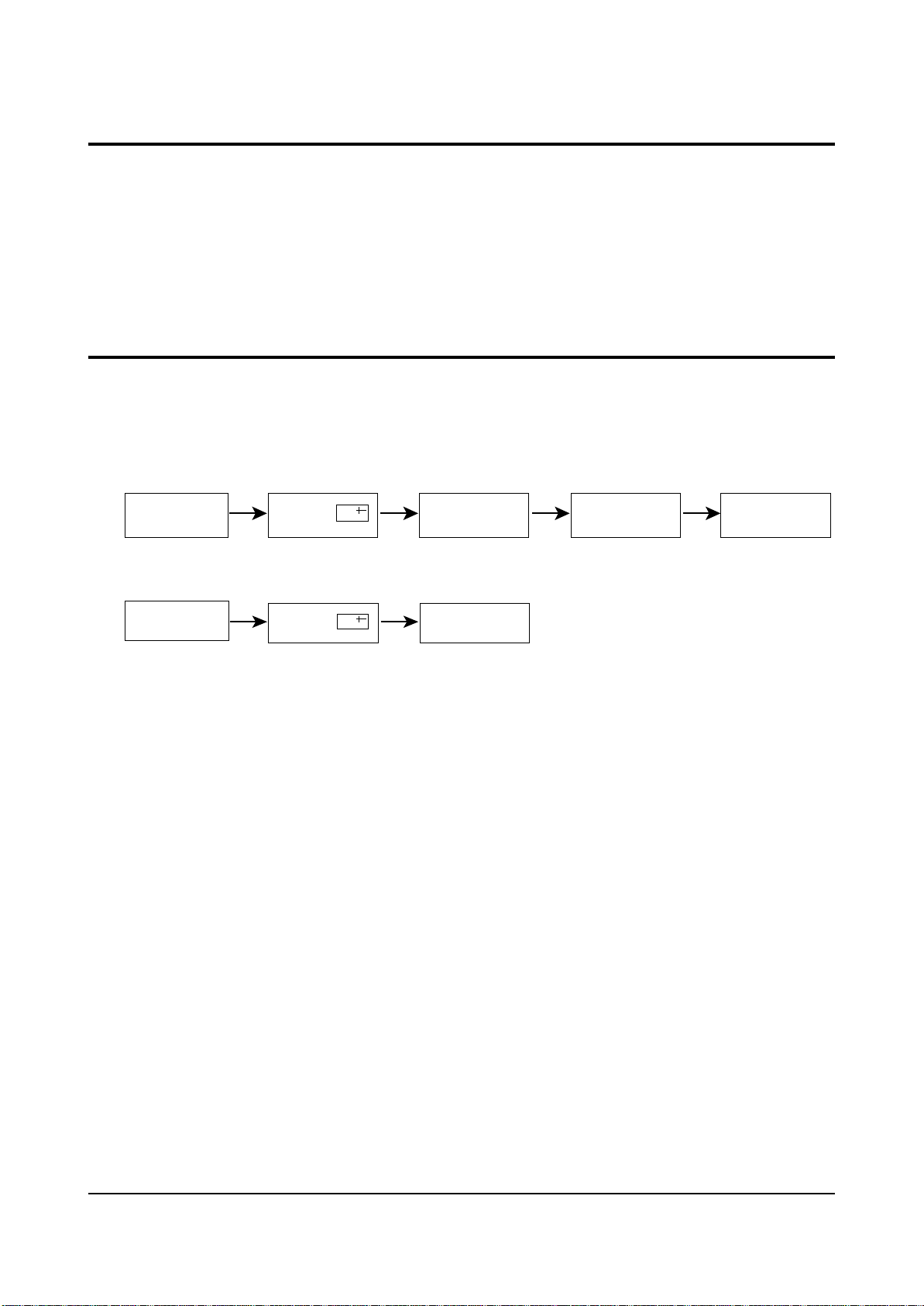
1. To enter the “Service Mode”, Press the remote-control keys in this sequence :
- If you do not have Factory remote-control
- If you have Factory remote-control
2-5-1 Service Mode
PICTURE OFF PICTURE ON
PICTURE ON
DISPLAY
DISPLAY
()
()
MENU
FACTORY
MUTE

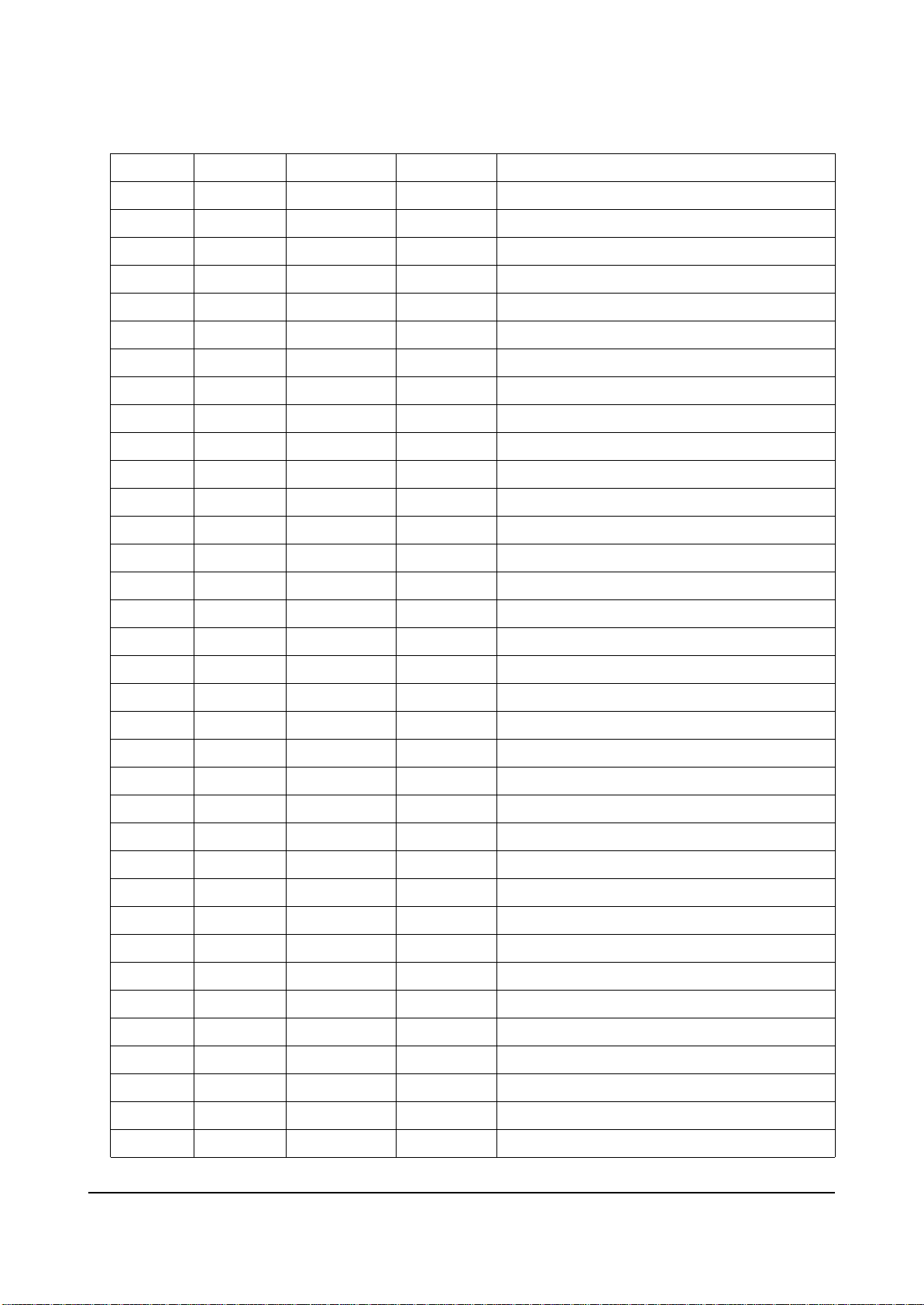
2-5-2 Factoy Mode OSD
ADJUST
OPTION
OPTION1
G2-ADJUST
RESET
SPM-836EE1
AGC
SCT
SBT
BLR
BLB
RG
GG
BG
VSL
VS
VA
HS
SC
CDL
30
13
10
30
30
30
30
30
22
25
43
37
28
13
STT
AKB
PDL
NDL
PSR
NSR
VOL
LCO
TXP
MVOL
FMWS
AGCS1
OMD
SCL
7
0
15
10
15
5
10
0
9
5
0
1
26
1
PWL
AGN
PEK
ACL
FCO
SCBT
TSC
SSP
PSNS
DPSR
DNSR
DCDL
SVM
VMA
12
1
2
0
0
45
40
15
1
15
15
13
0
3
HPAR
HBOW
EWID
EPAR
EUCN
ELCN
ETRP
VZ
FOAB
32
32
32
32
32
32
32
54
0
2-5-2(A) ADJUST
✴ TDA959X
Alignment and Adjustments
Samsung Electronics 2-3
FIX
Adjust
Adjust
Adjust
Adjust
Adjust
FIX
Adjust
FIX
Adjust
Adjust
Adjust
FIX
FIX
FIX
FIX
FIX
FIX
FIX
FIX
FIX
FIX
FIX
FIX
FIX
FIX
FIX
FIX
FIX
FIX
FIX
FIX
FIX
FIX
FIX
FIX
FIX
FIX
FIX
FIX
FIX
FIX
Adjust
Adjust
Adjust
Adjust
Adjust
Adjust
Adjust
FIX
FIX
Alignment and Adjustments
2-4 Samsung Electronics
OSD
AGC
SCT
SBT
BLR
BLB
RG
GG
BG
VSL
VS
VA
HS
SC
CDL
STT
AKB
PDL
NDL
PSR
NSR
VOL
LCO
TXP
MVOL
FMWS
AGCS1
OMD
SCL
PWL
AGN
PEK
ACL
FCO
SCBT
TSC
Range
0 ~ 63
0 ~ 23
0 ~ 23
0 ~ 63
0 ~ 63
0 ~ 63
0 ~ 63
0 ~ 63
0 ~ 63
0 ~ 63
0 ~ 63
0 ~ 63
0 ~ 63
0 ~ 15
0 ~ 7
0 ~ 1
0 ~ 15
0 ~ 15
0 ~ 23
0 ~ 23
0 ~ 63
0 ~ 1
0 ~ 15
0 ~ 50
0 ~ 1
0 ~ 3
0 ~ 63
0 ~ 3
0 ~ 15
0 ~ 1
0 ~ 3
0 ~ 1
0 ~ 1
0 ~ 63
0 ~ 23
Register
1Eh(D5-D0)
1Dh
1Bh
14h(D5-D0)
15h(D5-D0)
16h(D5-D0)
17h(D5-D0)
18h(D5-D0)
0Fh(D5-D0)
12h(D5-D0)
10h(D5-D0)
09h(D5-D0)
0Fh(D5-D0)
2Ah(D3-D0)
08h
2Ah(D4)
1Ah(D3-D0)
1Ah(D3-D0)
1Ch
1Ch
1Fh
27h(D7-D5)
87F2h(D5-D0)
Oh(D15-D0)
29h(D5)
28h(D2-D1)
05h(D5-D0)
04h(D5-D4)
04h(D3-D0)
29h(D7)
19h(D7-D6)
20h(D1)
21h(D0)
1Bh
19h(D5-D0)
Initial Value
30
13
10
30
30
30
30
30
22
25
43
37
28
13
7
0
15
10
15
5
10
0
9
5
0
1
26
1
12
1
2
0
0
40
40
Remark
RF AGC
Sub contrast(high light adjustment)
Sub brightness(low light adjustment)
Black level offset R(low light R adjustment)
Black level offset B(low light B adjustment)
White point R(high light R adjustment)
White point G(high light 25 fixed)
White point B(high light B adjustment)
Vertical slope
Vertical shift
Vertical amplitude
Horizontal shift
S-correction
Cathode drive level
Sub tint(NTSC only)
Black current stabilization
PAL Y-delay adjustment
NTSC Y-delay adjustment
PAL sub color gain adjustment
NTSC sub color gain adjustment
Initial vol adjustment
PLL demodulator frequency adjust( 0 : set )
TTX horizontal shift adjustment(Micom Memory Part)
Melody initial vol adjustment(MSP34XX)
Narrow-band sound PLL window selection
IF AGC speed
Off-set IF demodulator
Soft clipping level
Peak white limiting
FM demodulator gain
Peaking center frequency
Automatic color limiting
Forced color limiting
Screen brightness(different from INCH)
Sub Sharpness gain adjustment
 Loading...