

Page 1

Alignment and Adjustments
Samsung Electronics 4-1
4. Alignment and Adjustments
4-1 General Alignment Instructions
1. Usually, a color TV-VCR needs only slight
touch-up adjustment upon installation. Check
the basic characteristics such as height,
horizontal and vertical sync and focus.
2. Observe the picture for good black and white
details. There should be objectionable color
shading; if color shading is present,
demagnetize, perform purity and convergence
adjustments described below.
3. Use the specified test equipment or its
equivalent.
4. Correct impedance matching is essential.
5. Avoid overload. Excessive signal from a
sweep generator might overload the front-end
of the TV. When inserting signal markers, do
not allow the marker generator to distort test
results.
6. Connect the TV only to an AC power source
with voltage and frequency as specified on the
backcover nameplate.
7. Do not attempt to connect or disconnect any
wires while the TV is turned on. Make sure
that the power cord is disconnected before
replacing any parts.
8. To protect against shock hazard, use an
isolation transformer.
4-2 Automatic Degaussing
A degaussing coil is mounted around the
picture tube, so that external degaussing after
moving the TV should be unnecessary. But
the receiver must be properly degaussed upon
installation.
The degaussing coil operates for about 1
second after the power is switched ON. If the
set is moved or turned in a different direction,
the power should be OFF for at least 10
minutes.
If the chassis or parts of the cabinet become
magnetized, poor color purity will result. If
this happens, use an external degaussing coil.
Slowly move the degaussing coil around the
faceplate of the picture tube and the sides and
front of the receiver. Slowly withdraw the coil
to a distance of about 6 feet before turning
power OFF.
If color shading persists, perform the
following Color purity and Convergence
adjustments.
4-3 High Voltage Check
CAUTION : There is no high voltage adjustment
on this chassis. The B+ power supply should be
+135 volts (with full color- bar input and normal
picture level).
1. Connect a digital voltmeter to the second
anode of the picture tube.
2. Turn on the TV. Set the Brightness and
Contrast controls to minimum (zero beam
current).
3. Adjust the Brightness and contrast controls to
both extremes. Ensure that the high voltage
does not exceed 30 KV under any conditions.
Page 2

Alignment and Adjustments
4-2 Samsung Electronics
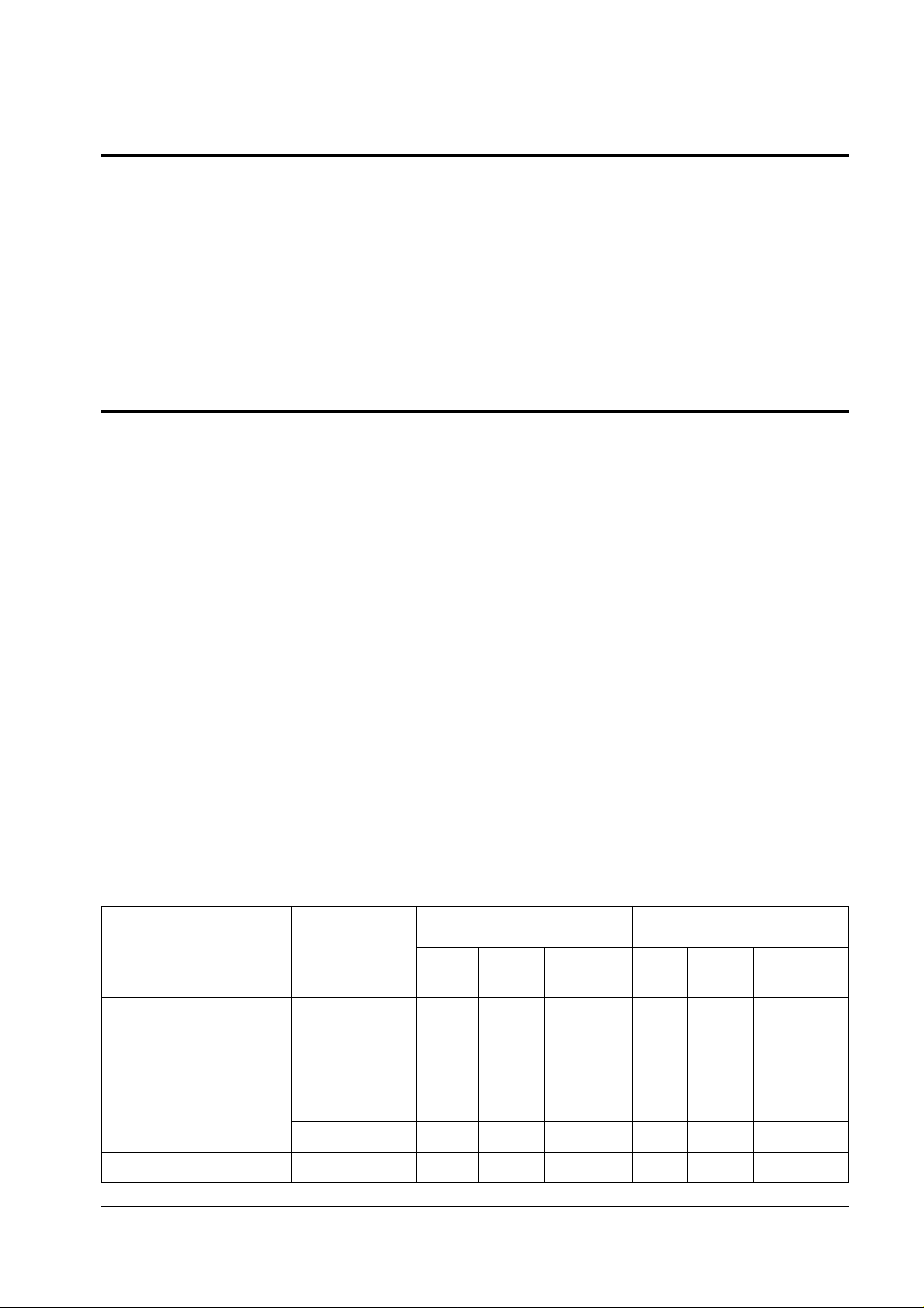
4-5 SCREEN Adjustment
1. Input Toshiba Pattern
2. Enter “Service Mode”.(Refer to “4-8-1 Service Mode”)
3. Select “G2-Adjust”.
4. Set the values as below.
4-4 FOCUS Adjustment
1. Input a black and white signal.
2. Adjust the tuning control for the clearest picture.
3. Adjust the FOCUS control for well defined scanning lines in the center area of the screen.
5. Turn the SCREEN VR until “MRCR G B” and “MRWDG” are green and those value are about 100.
(The incorrect SCREEN Voltage may result that “MRCR G B” and “MRWDG” should be red)
INCH / CRT
21PF/TOSHIBA
21” 1.7R/SDI
21” 1.7R/JCT
15 PF/SDI
No
1
2
3
4
IBRM
220
220
220
220
WDRV
35
35
35
35
CDL
180
180
200
180
COLR G B
(Smallest Value)
65
100
150
100
Table 1. Screen Adjustment Table
Page 3
Alignment and Adjustments
Samsung Electronics 4-3
4-6 E2PROM (IC902) Replacement
1. When IC902 is replaced, all adjustment data revert to the initial values.
So, all adjustment values when servicing should be readjusted.
2. After IC902 is replaced, connect the AC power supply cord.
3. Turn the power switch ON.
4. In stand-by, warm up the TV for at least 10 seconds.
5. Power on the TV.
4-7 White Balance Adjustment
■ Equipment : Color-Analyzer (CA-100)
■ Input Signal : Pattern signal (Toshiba pattern)
1. Select STANDARD from the menu.
2. Input an 100% White pattern.
3. Enter the “Service Mode”. (Refer to “4-8 Service Mode”)
4. Warm up the TV set at least for 30 minutes.
5. Input a Toshiba pattern signal.
6. Enter the “Video Adjust1”. (Refer to table 2.)
- Adjust “Sub Contrast” so that Y (luminance) becomes 65 ft ± 3.
- Use “Red Drive” and “ Blue Drive” to adjust High-Light (x : 265, y : 265)
- Adjust “Sub Bright” so that Y (luminance) becomes 1.2ft ± 0.3.
- Use “Red Cutoff” and “Blue Cutoff” to adjust Low-Light (x : 265, y : 265).
7. Adjust CA-100 so that the final adjustment value can be fixed.
8. Use the Channel Up/Down (▲/▼) buttons to move the cursor on the adjustment modes.
9. Use the Volume +/- buttons to change the adjustment value.
Area
East South Asia
Middle East Asia
& Africa
CIS
Inch
21PF
21” 1.7R
15PF
21PF
21” 1.7R
21PF
High
X
Y
Luminance
(ft)
Low
X
Y
Luminance
(ft)
265
265
265
290
290
272
265
265
265
300
300
270
65
60
95
65
55
65
265
265
265
290
290
265
265
265
265
300
300
266
1.2
1.5
2.0
1.2
1.5
2.7
Table 2. White Balance Table
Page 4

Alignment and Adjustments
4-4 Samsung Electronics
4-8 Factory Adjustment
1. To enter the “Service Mode”, Press the remote-control keys in this sequence :
- If you do not have Factory remote-control
- If you have Factory remote-control
2. After the Service Mode is entered, the initial screen is as shown in the figure below.
3. Use the Channel Up/Down buttons to move the cursor in the adjustment parameters.
Note :
- When CRT, CRT PCB, FBT, E
2
PROM (sometimes MICOM) is replaced, the adjustment values
should be controlled.
- After the Service adjustment is completed, Do not select “Reset” in the service mode menu.
(After above procedure is done, power is on initially and the “Plug and Play” will be operated.)
4-8-1 Service Mode
*
These hexa digits are check sum value which
depends on the MICOM version.
If check sum value is changed, the value of
E
2
PROM Data newly initialed.
PICTURE OFF PICTURE ON
PICTURE ON
xx xx xx
Others
DISPLAY
DISPLAY
*
()
()
MENU
FACTORY
MUTE
Page 5

Alignment and Adjustments
Samsung Electronics 4-5
4-8-2 Deflection (Memory Data)
4-8-2(A) GEOMETRIC ADJUSTMENT VALUE
No.
1
2
3
4
5
6
7
8
9
10
11
12
13
14
15
16
17
OSD
V Shift
V Amp
V Slope
V SC
H EW
H Trapizium
H Parabola
H Symmetry
H Corner
H Shift
PIP Contrast
PIP Tint
PIP H.Move
PIP V.Move
PIP PAL V.Pos
PIP NTSC V.Pos
PIP H.Pos
Range
-128 ~ 127
-128 ~ 127
-128 ~ 127
-128 ~ 127
-128 ~ 127
-128 ~ 127
-128 ~ 127
-128 ~ 127
-128 ~ 127
-128 ~ 127
0 ~ 15
0 ~ 63
0 ~ 7
0 ~ 7
0 ~ 255
0 ~ 255
0 ~ 255
Function
Vertical Shift
Vertical Amplitude
Vertical Slope
Vertical S-Correction
Horizontal East West Width
Horizontal Trapezium
Horizontal Parabora
Horizontal Symmetry
Horizontal Corner
Horizontal Shift
PIP Contrast
PIP Tint (Hue)
PIP Horizontal Move (PIP Picture)
PIP Vertical Move (PIP Picture)
PIP PAL System Verical Position (PIP Box)
PIP NTSC System Vertical Position (PIP Box)
PIP Horizontal Position (PIP Box)
Remark
PIP Option
Fixed Value
Initial
Value
-54
15
-2
-15
61
-8
-3
12
-32
10
0
0
0
3
33
33
42
Page 6

Alignment and Adjustments
4-6 Samsung Electronics
4-8-2(B) SCREEN CHANGE (I2C BUS GEOMETRIC ADJUSTMENT)
1 V Shift
V Slope
2
3 H EW
6 V Amp
V SC
7
8
H Trapizium
4 H Parabola
5 H Corner
9
10
H Symmetry
H Shift
Page 7

Alignment and Adjustments
Samsung Electronics 4-7
4-8-2(C) VIDEO ADJUST 1
No.
1
2
3
4
5
6
7
8
9
10
11
12
13
14
15
OSD
Red Cufoff
Green Cutoff
Blue Cutoff
Red Drive
Green Drive
Blue Drive
Sub Bright
Sub Contrast
Sub Color
Sub Tint
BCL Threshold
BCL Gain
BCL Time
TTX Contrast
YC Delay
Range
0 ~255
0 ~255
0 ~255
0 ~255
0 ~255
0 ~255
0 ~ 200
0 ~ 63
0 ~ 27
0 ~ 100
0 ~ 255
0 ~ 15
0 ~ 15
0 ~ 255
0 ~ 8
Function
Adjust Red Cutoff Level
Adjust Green Cutoff Level
Adjust Blue Cutoff Level
Adjust Red Output Gain
Adjust Green Output Gain
Adjust Blue Output Gain
Adjust Brightness Level
Adjust Contrast Level
Adjust Color Level
Adjust Tint
Adjust Beam Control Limit
Refer to Note 1.
Adjust OSD/TTX Contrast
Refer to Table 3.
Remark
Low Light
High Light
Low Light
High Light
Not to be adjusted
Refer to table 4.
Not to be adjusted
Refer to table 4.
Initial
Value
127
127
127
127
127
127
100
52
27
30
77
8
13
90
*
Fixed Value
Note 1. Beam Control Limit Characteristic
WDRGB
BCL THESHOLD
1.8mA
1.6mA
MIN
BCL GAIN
MAX
Table 3. YC Delay Adjustment Table
YC
Delay
Value
PAL
Def.
3
BG
3
DK
6
I
6
Def.
3
BG
3
DK
5
I
8
SECAM
NTSC
Def.
0
beam
50
IRE
Page 8

Alignment and Adjustments
4-8 Samsung Electronics
Table 4. Variable Factory Item
Area
East South Asia
Middle East Asia
& Africa
CIS
Inch
21PF
21” 1.7R
15PF
21PF
21” 1.7R
21PF
BCL Threshold
TTX Contrast
Remark
62
40
40
62
40
62
90
90
100
90
90
90
OSD
B stretch-BTHR
B stretch-BTLT
B stretch-BAM
Coring
RGB Bright
RGB Contrast
EHT Time
EHT Compensation
✐
No.
1
2
3
4
5
6
7
8
Range
0 ~ 55
0 ~ 15
0 ~ 31
0 ~ 31
0 ~ 255
80
0 ~ 15
0 ~ 255
Initial
Value
50
8
4
31
0
0
0
60
Function
Black Stretch Threshold
Black Stretch Tilt Position
Black Stretch Amount
Luma Peaking Filter Coring
External RGB Brightness
External RGB Contrastness
Electronic High Tension Response Time
EHT Compensation Coefficient
Remark
Coring : The Value of Center Frequency for the active bandwidth.
4-8-2(D) VIDEO 2 ADJUST
1
✐
1
Page 9

Alignment and Adjustments
Samsung Electronics 4-9
4-8-2(E) VIDEO 3 ADJUST
No.
1
2
3
4
5
6
7
OSD
Peak Threshold
Soft Limit Slope B
Hard Limit
Peak Video Ref
Peak Video Gain
ACC-REF(PAL/NTSC)
ACCR(SECAM)
Range
0 ~ 255
0 ~ 15
0 ~ 255
0 ~ 4
0 ~ 5
0 ~ 20
0 ~ 39
Initial
Value
255
2
255
0
0
20
21
Function
White Peak Level Threshold
Refer to Picture Below
White Peak Level Threshold Reference
White Peak Level Threshold Gain
Auto Color Control
Remark
Refer to Note
Below
“Soft Limit” is that Limitting
the peak white without
feed-back, but “Peak Limit” is
that with feed-back for white
peak level
Note 2. Soft Limit & Hard Limit Characteristics
✐
Slope 1 [0...15]
0
2
4
6
8
10
12
14
tilt 2 [0...511]
Output
511
400
300
200
100
0
tilt 1 [0...511]
0
100 200 300 400 500 600 700 800 900 1023
Part 1 Part 2
0
2
4
6
8
10
12
14
Slope 2 [0...15]
Hard limiter
Soft Limit Slope B
range=256...511
Li
Page 10

Alignment and Adjustments
4-10 Samsung Electronics
ITEM(OSD) Control Description
Language ESAsia ENGLISH/VIETNAM/THAI/INDONESIA/MALAYSIA
A2/NICAM A2 Stereo / Nicam Stereo Model
Sound Virtual Dolby Virtual Dolby Model
Mono Mono Model
Line-Stereo Line stereo Model
4:3 Normal / Zoom / 16:9
Wide Wide CRT ( 16:9 )
CRT Q(12.8:9) Plus / Normal / Zoom / 16:9
4:3-16:9 Normal / Zoom
Q - 16:9 Plus / Normal / Zoom
1Scart Built in 1 Scart Model
2Scart Built in 2 Scart Model
2scart+S Built in 2 Scart +SVHS JACK Model
AV Mode 1RCA Built in RCA 6P / RCA 4P Model
2RCA Built in RCA 9P Model
2RCA+S Built in RCA 9P + SVHS JACK Model
2RCA+S+D Built in RCA 9P + SVHS JACK Model +
DVD JACK Model
2RCA+D Built in RCA 9P + DVD JACK Model
X-Ray
On X-ray detection function on
Off X-ray detection function off
Tilt Control
On CRT Tilt control function on ( wide / 29PF CRT)
Off CRT Tilt control function off
Auto FM
On automatic change from NICAM to FM depends on NICAM error rate
Off automatic change from NICAM to FM depends on NICAM syncronization
PIP
Off no PIP function
1 - tuner 1 Tuner PIP function
2 - tuner 2 Tuner PIP function
West Europe English/German/Skandinavian/Italian
French/Spainsh/Czech
East Europe Polish/Czech/Rumanian/Slovenian/Croatian/
French/Skandinavian/German/Italian
Txt Language Russian Russian/Ukranian/Estonian/Czech/German/
Lettish/English
Greek-Turkey English/Turkey/Greek/French/Skandinavian/German/Spainsh/Italian
Arabic English/Arabic/French
Farsi English/Farsi/French
Arab-Hebrew Arabic/Hebrew
LNA
On Built in LNA Tuner
Off Built in Normal Tuner
Equalizer
On Include in Equalizer function ( MSP34X0D)
Off Without Equalizer function (MSP34X5D)
High deviate
On High deviation mode on MSP34XX
Off Normal mode on MSP34XX
No.
1
2
3
4
5
6
7
8
9
10
11
12
13
4-8-2(F) OPTION 1
Micom Spec : SIM-806EA
TTX On/Off
On TTX Model
Off W/O - TTX Model
Page 11

Alignment and Adjustments
Samsung Electronics 4-11
ITEM(OSD) Control Description
Language
Arab English/Arab/French/Pakistan
Iran English/Persian/French/Turkey
Libya English/Libya/French
CIS English/Russia
A2/NICAM A2 Stereo / Nicam Stereo Model
Sound
Virtual Dolby Virtual Dolby Model
Mono Mono Model
Line-Stereo Line stereo Model
4:3 Normal / Zoom / 16:9
Wide Wide CRT ( 16:9 )
CRT Q(12.8:9) Plus / Normal / Zoom / 16:9
4:3-16:9 Normal / Zoom
Q - 16:9 Plus / Normal / Zoom
1Scart Built in 1 Scart Model
2Scart Built in 2 Scart Model
2scart+S Built in 2 Scart +SVHS JACK Model
AV Mode 1RCA Built in RCA 6P / RCA 4P Model
2RCA Built in RCA 9P Model
2RCA+S Built in RCA 9P + SVHS JACK Model
2RCA+S+D Built in RCA 9P + SVHS JACK Model + DVD JACK Model
2RCA+D Built in RCA 9P + DVD JACK Model
X-Ray
On X-ray detection function on
Off X-ray detection function off
Tilt Control
On CRT Tilt control function on ( wide / 29PF CRT)
Off CRT Tilt control function off
Auto FM
On automatic change from NICAM to FM depends on NICAM error rate
Off automatic change from NICAM to FM depends on NICAM syncronization
PIP
Off no PIP function
1 - tuner 1 Tuner PIP function
2 - tuner 2 Tuner PIP function
West Europe English/German/Skandinavian/Italian/French/Spainsh/Czech
East Europe Polish/Czech/Rumanian/Slovenian/Croatian/
French/Skandinavian/German/Italian
Txt Language Russian Russian/Ukranian/Estonian/Czech/German/Lettish/English
Greek-Turkey English/Turkey/Greek/French/Skandinavian/German/Spainsh/Italian
Arabic English/Arabic/French
Farsi English/Farsi/French
Arab-Hebrew Arabic/Hebrew
LNA
On Built in LNA Tuner
Off Built in Normal Tuner
Equalizer
On Include in Equalizer function ( MSP34X0D)
Off Without Equalizer function (MSP34X5D)
High deviate
On High deviation mode on MSP34XX
Off Normal mode on MSP34XX
No.
1
2
3
4
5
6
7
8
9
10
11
12
13
4-8-2(G) OPTION 2
Micom Spec : SIM-806MA
TTX On/Off
On TTX Model
Off W/O - TTX Model
Page 12

Alignment and Adjustments
4-12 Samsung Electronics
ITEM(OSD) Control Description
A2/NICAM A2 Stereo / Nicam Stereo Model
SOUND
Virtual Dolby Virtual Dolby Model
Mono Mono Model
Line-Stereo Line stereo Model
4:3 Normal / Zoom / 16:9
Wide Wide CRT ( 16:9 )
CRT Q(12.8:9) Plus / Normal / Zoom / 16:9
4:3-16:9 Normal / Zoom
Q - 16:9 Plus / Normal / Zoom
1Scart Built in 1 Scart Model
2Scart Built in 2 Scart Model
2scart+S Built in 2 Scart +SVHS JACK Model
A/V Mode 1RCA Built in RCA 6P / RCA 4P Model
2RCA Built in RCA 9P Model
2RCA+S Built in RCA 9P + SVHS JACK Model
2RCA+S+D Built in RCA 9P + SVHS JACK Model + DVD JACK Model
2RCA+D Built in RCA 9P + DVD JACK Model
X-Ray
On X-ray detection function on
Off X-ray detection function off
Tilt Control
On CRT Tilt control function on ( wide / 29PF CRT)
Off CRT Tilt control function off
Auto FM
On automatic change from NICAM to FM depends on NICAM error rate
Off automatic change from NICAM to FM depends on NICAM syncronization
Off no PIP function
PIP 1 - tuner 1 Tuner PIP function
2 - tuner 2 Tuner PIP function
LNA
On Built in LNA Tuner
Off Built in Normal Tuner
Equalizer
On Include in Equalizer function ( MSP34X0D)
Off Without Equalizer function (MSP34X5D)
High deviate
On High deviation mode on MSP34XX
Off Normal mode on MSP34XX
No.
1
2
3
4
5
6
7
8
9
10
4-8-2(H) OPTION 3
Micom Spec : SIM-806E1
Page 13

Alignment and Adjustments
Samsung Electronics 4-13
ITEM(OSD)
MRCR G B
MRWDG
IBRM
WDRV
CDL
COLR G B
Control
No Control
No Control
0 ~ 255
0 ~ 255
0 ~ 255
0 ~ 255
Description
Measure of Cutoff Gain
Measure of Green Drive Gain
Internal Brightness offset value by Read
Measurement
White Drive Value
Cathode Drive Level
Cathode Cutoff Level
Initial Value
110 110 110
110
220 Refer to Screen adjust
table
35
180
65 70 75
No.
1
2
3
4
5
6
4-8-2(I) G2 - ADJUSTMENT
ITEM(OSD)
VSU
H QEW
H Zoom Parabola
H 16:9 Parabola
TTX Position
Mono Sound
System
V Slice level
Melody Volume
Control
96 ~ 111
-30 ~ 30
-15 ~ 15
-15 ~ 15
-30 ~ 30
BG
DK
I
M
0 ~ 3
0 ~ 20
Description
Vertical Setup TIme (Large Value time)
Horizontal EW data offset to plus screen
Horizontal Palabola offset to zoom screen
Horizontal Palabola offset to 16:9 screen
Horizontal shift in TTX Mode
Initial Sound System of Mono Model
Vertical Sync Slice level Setting
Melody Sound Volume level Setting
Initial Value
108
0
8
-18
0
BG
2
5
No.
1
2
3
4
5
6
7
8
4-8-2(J) OTHERS
Page 14

4-9-1 Pin Layout
Alignment and Adjustments
4-14 Samsung Electronics
4-9 MICOM
Write Protect
EEPROM SDA
EEPROM SCL
Bus-Stop
Main SDA
Main SCL
Sound Reset
Video Reset
VDD 2.5V
GND
VDD 3.3V
CVBS Input
VDD 2.5V
GND
AFT
Scart1 Ident
Scart2 Ident
Key 1
H-Sync
V-Sync
Key 3
Key 2
X-Ray Protect
IR Input
Stand-By LED
Time LED
1
2
3
4
5
6
7
8
9
10
11
12
13
14
15
16
17
18
19
20
21
22
23
24
25
26
I/O
I/O
IO
I/O
I/O
I/O
I/O
I/O
ADC
ADC
ADC
ADC
I/O
I/O
I/O
I/O
I/O
I/O
S
D
A
5
5
5
X
PWM
I/O
I/O
I/O
52
51
50
49
48
47
46
45
44
43
42
41
40
39
38
37
36
35
34
33
32
31
30
29
28
27
Tilt
N.C.
Power
Sound Mute
N.C.
N.C.
PX. Y
PX. Y
VDD 3.3V
GND
VDD 2.5V
CORE
OSD-B
OSD-G
OSD-R
VDD 2.5V
GND
X-TAL Out
X-TAL In
MICOM Reset
N.C.
N.C.
VDD 3.3V
GND
N.C.
Relay
Page 15

Alignment and Adjustments
Samsung Electronics 4-15
4-9-2 Pin Assignment Specification
DESCRIPTION
EEPROM Write Protection
EEPROM Serial Data Line
EEPROM Serial Clock Line
Disable Micom IIC
Peripheral IC Serial Data Line
Peripheral IC Serial Clock Line
MSP IC Initial Control
VDP IC Initial Control
TTX CVBS Input
Analog B+
Analog Ground
Auto Fine Tuning Control
Scart1 Ident
Scart2 Ident
Key1 Input
Horizontal Sync Input
Vertical Sync Input
Key3 Input
Key2 Input
X-Ray Protection
Remocon Signal Input
LED Drive Output(Red)
LED Drive Output(Green)
PIN NO
1
2
3
4
5
6
7
8
9
10
11
12
13
14
15
16
17
18
19
20
21
22
23
24
25
26
FUNCTION
I/O
I/O
I/O
I/O
I/O
I/O
I/O
I/O
Vdd
GND
Vdd
CVBS
Vdd
GND
ADC
ADC
ADC
ADC
HS
VS
I/O
I/O
I/O
I/O
I/O
I/O
ASSIGN
Write Protect
ROM SDA
ROM SCL
Bus Stop
Main SDA
Main SCL
Sound Reset
Video Reset
VDD 2.5V
VDD 3.3V
CVBS Input
VDD 2.5V
AFT
SC1-ID
SC2-ID
Key1
H-Sync
V-Sync
Key3
Key2
X-Ray
IR-In
STD-LED
TIM-LED
IN/OUT
Out
I/O
I/O
In
I/O
I/O
Out
Out
In
In
In
In
In
In
In
In
In
In
In
Out
Out
ACTIVE H/L
Low
Low
Low
Low
Page 16

Alignment and Adjustments
4-16 Samsung Electronics
4-9-2 Pin Assignment Specification (Continued)
PIN NO
27
28
29
30
31
32
33
34
35
36
37
38
39
40
41
42
43
44
45
46
47
48
49
50
51
52
FUNCTION
I/O
N.C.
GND
Vdd
N.C.
N.C.
Reset
X-In
X-Out
GND
Vdd
R
G
B
COR
Vdd
GND
Vdd
I/O
I/O
N.C.
N.C.
I/O
I/O
N.C.
I/O
ASSIGN
Relay
VDD 3.3V
Reset
X-TAL In
X-TAL Out
VDD 2.5V
OSD-R
OSD-G
OSD-B
CORE
VDD 2.5V
VDD 3.3V
PX.Y
PX.Y
S-Mute
Power
IN/OUT
Out
In
In
Out
Out
Out
Out
Out
In
Out
Out
Out
ACTIVE H/L
Low
Low
6MHz
6MHz
High
Low
DESCRIPTION
Activate Degausssing Coil
Not Used (Programmed Gound Level)
Analog Ground
Not Used (Programmed Gound Level)
Not Used (Programmed Gound Level)
Micom Hardware Reset
Crystal Oscillation Input
Crystal Oscillation Output
Analog Ground
Analog B+
OSD/TTX Output (Red)
OSD/TTX Output (Green)
OSD/TTX Output (Blue)
Fast Blank/Half Contrast Output
When The Caption Function Adopted, Used.
Not Used (Programmed Gound Level)
Sound Amp Mute
Picture On/Off Control
Not Used (Programmed Gound Level)
 Loading...