

Owner’s
Instructions
COLOR TELEVISION
...........................................................................................................................
.............
AA68-03255A-00
CL29A10
CL34A10
CL29M6
IMPORTER
Samsung Electronics Mexico. S.A. de C.V.
Saturno No. 44, Col. Nueva Industrial
Vallejo
Gustavo A. Madero C.P. 07700, Mexico
D.F. Mexico
TEL) 52-55-5747-5100
EXPORTER
Samsung Electronics co., Ltd.
416, Mae tan-3dong, Youngtong-Gu,
Suwon City, Kyungki-Do Korea
2
Warning! Important
Safety Instructions
CAUTION: TO REDUCE THE RISK OF ELECTRIC SHOCK, DO NOT
REMOVE COVER (OR BACK). NO USER SERVICEABLE PARTS INSIDE.
REFER SERVICING TO QUALIFIED SERVICE PERSONNEL.
This symbol indicates high voltage is present inside. It is
dangerous to make any kind of contact with any inside part of
this product.
This symbol alerts you that important literature concerning
operation and maintenance has been included with this product.
Note to CATV system installer: This reminder is provided to call CATV system
installer’s attention to Article 820-40 of the National Electrical Code (Section 54 of
Canadian Electrical Code, Part I), that provides guidelines for proper grounding
and, in particular, specifies that the cable ground shall be connected to the
grounding system of the building as close to the point of cable entry as practical.
Caution: FCC/CSA regulations state that any unauthorized changes or modifications to this equipment may void the user’s authority to operate it.
Caution: To prevent electric shock, match the wide blade of plug to the wide slot,
and fully insert the plug.
Attention: pour eviter les chocs electriques, introduire la lame le plus large de la
fiche dans la borne correspondante de la prise et pousser jusqu’au fond.
Important: One Federal Court has held that unauthorized recording of
copyrighted TV programs is an infringement of U.S. copyright laws.
Certain Canadian programs may also be copyrighted and any unauthorized
recording in whole or in part may be in violation of these rights.
To prevent damage which may result in fire or electric shock
hazard, do not expose this appliance to rain or moisture.
CAUTION
RISK OF ELECTRIC SHOCK
DO NOT OPEN
KS7A(ET)Latin_ENG 12/7/03 4:53 PM Page 2
3
Thank You for Choosing Samsung
Thank you for choosing Samsung! Your new Samsung TV represents the latest in television
technology. We designed it with easy-to-use on-screen menus and closed captioning capabilities, making it one of the best products in its class. We are proud to offer you a product that
will provide convenient, dependable service and enjoyment for years to come.
Important Safety Information
Always be careful when using your TV receiver. To reduce the risk of fire, electrical shock,
and other injuries, keep these safety precautions in mind when installing, using, and
maintaining your machine.
• Read all safety and operating instructions before operating your TV.
• Keep the safety and operating instructions for future reference.
• Heed all warnings on the TV receiver and in the operating instructions.
• Follow all operating and use instructions.
• Unplug the TV receiver from the wall outlet before cleaning. Use a damp cloth; do not use
liquid or aerosol cleaners.
• Never add any attachments and/or equipment without approval of the manufacturer. Such
additions can increase the risk of fire, electric shock, or other personal injury.
•Do not use the TV receiver where contact with or immersion in water is a possibility, such as
near bath tubs, sinks, washing machines, swimming pools, etc.
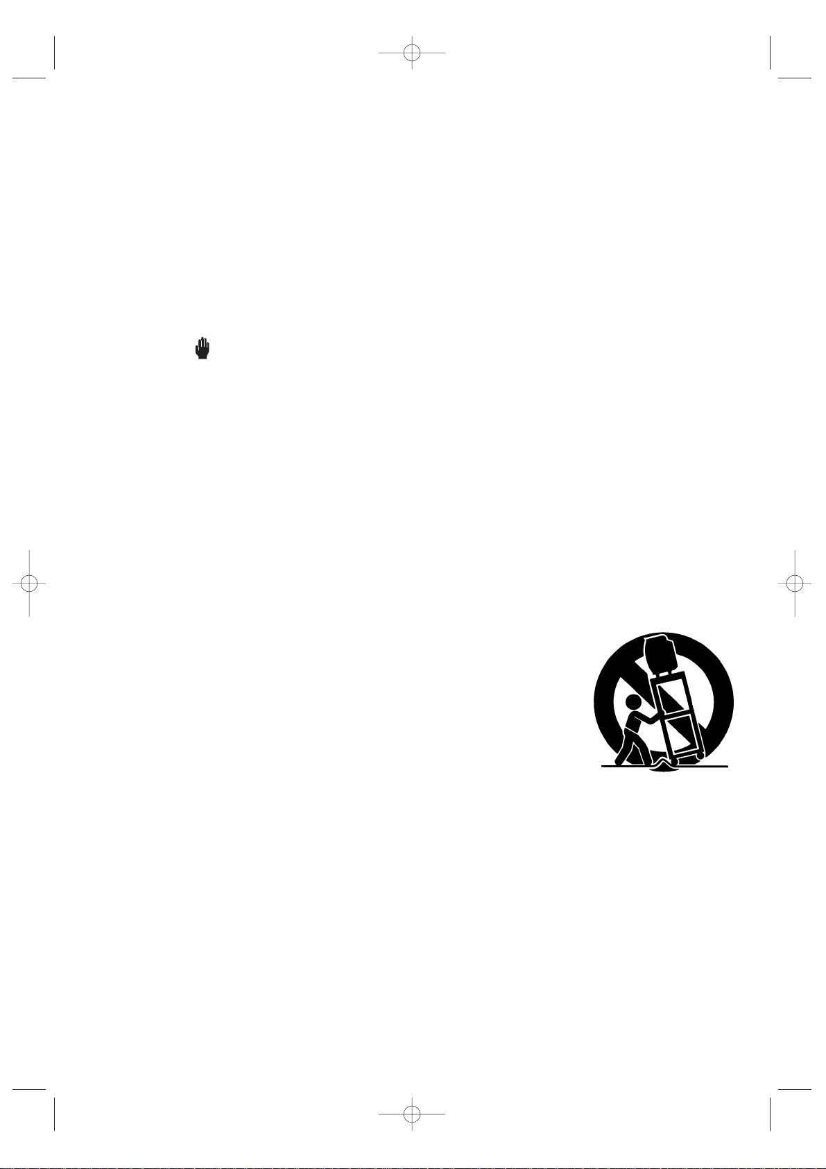
• Do not place the TV on an unstable cart, stand, tripod, bracket, or
table where it can fall. A falling TV can cause serious injury to a
child or adult, and serious damage to the appliance. Use only with
a cart, stand, tripod, bracket, or table recommended by the manufacturer or sold with the TV. Follow the manufacturer’s instructions when mounting the unit, and use a mounting accessory recommended by the manufacturer. Move the TV and cart with care.
Quick stops, excessive force, and uneven surfaces can make the
unit and cart unsteady and likely to overturn.
•Provide ventilation for the TV receiver. The unit is designed with slots in the cabinet for ventilation to protect it from overheating. Do not block these openings with any object, and do
not place the TV receiver on a bed, sofa, rug, or other similar surface. Do not place it near a
radiator or heat register. If you place the TV receiver on a rack or bookcase, ensure that there
is adequate ventilation and that you’ve followed the manufacturer’s instructions for mounting.
• Operate your TV receiver only from the type of power source indicated on the marking label.
If you are not sure of the type of power supplied to your home, consult your appliance dealer
or local power company.
• Use only a grounded or polarized outlet. For your safety, this TV is equipped with a polarized
alternating current line plug having one blade wider than the other. This plug will fit into the
power outlet only one way. If you are unable to insert the plug fully into the outlet, try
reversing the plug. If the plug still does not fit, contact your electrician to replace your outlet.
KS7A(ET)Latin_ENG 12/7/03 4:53 PM Page 3
4
•Protect the power cord. Power supply cords should be routed so that they will not be walked
on or pinched by items placed on or against them. Pay particular attention to cord placement
at plugs, convenience receptacles, and at the point where they exit from the unit.
• Unplug the TV receiver from the wall outlet and disconnect the antenna or cable system during a lightning storm or when left unattended and unused for long periods of time. This will
prevent damage to the unit due to lightning and power-line surges.
• An outside antenna system should not be placed in the vicinity of overhead power lines or
other electric light or power circuits or where it can fall into such power lines or circuits.
Avoid overhead power lines: When installing an outside antenna system, be extremely careful
to keep from touching the power lines or circuits. Contact with such lines might be fatal.
• Do not overload the wall outlet or extension cords. Overloading can result in fire or electric
shock.
• Do not insert foreign objects through openings in the unit, as they may touch dangerous
voltages or cause damage. Never spill liquid of any kind on the TV receiver.
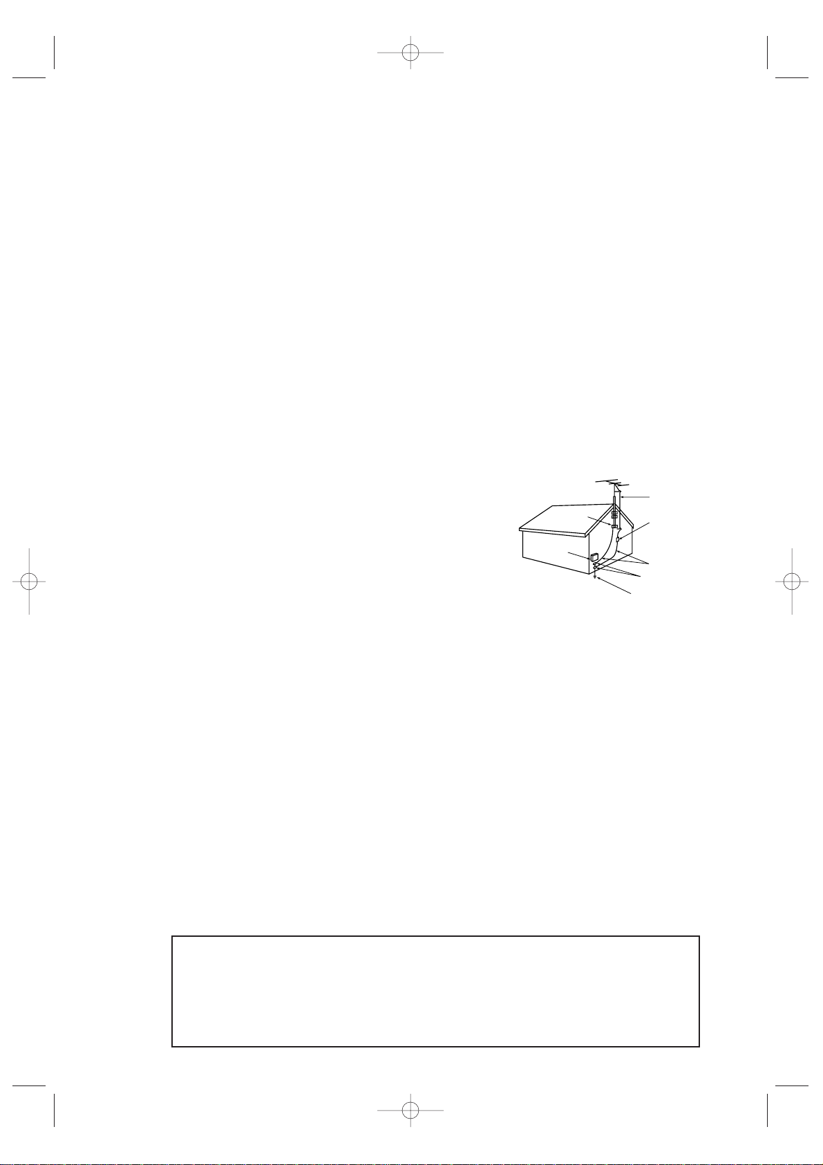
•Ground outdoor antennas. If an outside antenna or cable
system is connected to the TV receiver, be sure the
antenna or cable system is grounded so as to provide
some protection against voltage surges and built-up static
charges. Read information with respect to proper
grounding of the mast and supporting structure,
grounding of the lead-in wire to an antenna
discharge unit, size of grounding conductors, location of
antenna-discharge unit, connection to grounding
electrodes, and requirements for the grounding electrode.
• Do not attempt to service the TV receiver yourself. Refer all servicing to qualified service
personnel. Unplug the unit from the wall outlet and refer servicing to qualified service
personnel under the following conditions:
- When the power-supply cord or plug is damaged
- If liquid has been spilled on the unit or if objects have fallen into the TV
- If the TV receiver has been exposed to rain or water
- If the TV receiver does not operate normally by following the operating instructions
- If the TV receiver has been dropped or the cabinet has been damaged
- When the TV receiver exhibits a distinct degradation in performance
• If you make adjustments yourself, adjust only those controls that are covered by the operating instructions. Adjusting other controls may result in damage and will often require extensive work by a qualified technician to restore the TV receiver to normal.
• When replacement parts are required, be sure the service technician uses replacement parts
specified by the manufacturer or those that have the same characteristics as the original part.
Unauthorized substitutions may result in additional damage to the unit.
• Upon completion of any service or repairs to this TV receiver, ask the service technician to
perform safety checks to determine that the TV receiver is in a safe operating condition.
This device complies with part 15 of the FCC Rules. Operation is subject to the
following two conditions:
(1) This device may not cause harmful interference, and
(2) This device must accept any interference that may cause undesired operation.
This television receiver provides display of television closed captioning in accordance
with §15.119 of the FCC rules.
KS7A(ET)Latin_ENG 12/7/03 4:53 PM Page 4
EXAMPLE OF
ANTENNA GROUNDING
GROUND CLAMP
ELECTRIC
SERVICE
EQUIPMENT
NEC NATIONAL ELECTRICAL CODE
ANTENNA
LEAD IN WIRE
ANTENNA
DISCHARGE UNIT
(NEC SECTION 810-20)
GROUNDING
CONDUCTORS
(NEC SECTION 810-21)
GROUND CLAMPS
POWER SERVICE GROUNDING
ELECTRODE SYSTEM
(NEC ART 250, PART H)

5
1) Read these instructions.
2) Keep these instructions.
3) Heed all warnings.
4) Follow all instructions.
5) Do not use this apparatus near water.
6) Clean only with dry cloth.
7) Do not block any ventilation openings, Install in accordance with the manufacturer’s
instructions.
8) Do not install near any heat sources such as radiators, heat registers, or other apparatus
(including amplifiers) that produce heat.
9) Do not defeat the safety purpose of the polarized or grounding-type plug. A polarized
plug has two blades with one wider than the other. A grounding type plug has two blades
and a third grounding prong. The wide blade or the third prong are provided for your
safety. If the provided plug does not fit into your outlet, consult an electrician for replacement of the obsolete outlet.
10) Protect the power cord from being from being walked on or pinched particularly at plugs,
convenience receptacles, and the point where they exit from the apparatus.
11) Only use attachments/accessories specified by the manufacturer.
12) Use only with cart, stand, tripod, bracket, or table specified by the manufacturer, or sold
with the apparatus. When a used, caution when moving the cart/apparatus combination to
avoid injury from tip-over.
13) Unplug this apparatus. When a cart is used, use caution when moving the cart/apparatus
combination to avoid injury from tip-over.
14) Refer all servicing to qualified service personnel. Servicing is required when the apparatus
has been damaged in any way, such as power-supply cord or plug is damaged, liquid has
been spilled or objects have fallen into the apparatus, the apparatus has been exposed to
rain or moisture, does not operate normally, or has been dropped.
DOUBLE INSULATED - When servicing
use only identical replacement parts.
KS7A(ET)Latin_ENG 12/7/03 4:53 PM Page 5

CONTENTS
6
Chapter 1: Your New TV . . . . . . . . . . . . . . . . 8
List of Features . . . . . . . . . . . . . . . . . . . . . . . . . . . . . . . . . . . . . . . . . . . 8
Familiarizing Yourself with The TV . . . . . . . . . . . . . . . . . . . . . . . . . . . . 9
Front Panel Buttons . . . . . . . . . . . . . . . . . . . . . . . . . . . . . . . . 9
Side Panel Jacks . . . . . . . . . . . . . . . . . . . . . . . . . . . . . . . . . . 10
Rear Panel Jacks . . . . . . . . . . . . . . . . . . . . . . . . . . . . . . . . . . 11
Remote Control. . . . . . . . . . . . . . . . . . . . . . . . . . . . . . . . . . . 12
Chapter 2: Installation . . . . . . . . . . . . . . . . . 14
Connecting VHF and UHF Antennas . . . . . . . . . . . . . . . . . . . . . . . . . 14
Antennas with 300-ohm Flat Twin Leads . . . . . . . . . . . . . . . 14
Antennas with 75-ohm Round Leads . . . . . . . . . . . . . . . . . . 15
Separate VHF and UHF Antennas . . . . . . . . . . . . . . . . . . . . . 15
Connecting Cable TV . . . . . . . . . . . . . . . . . . . . . . . . . . . . . . . . . . . . . 15
Connecting a VCR. . . . . . . . . . . . . . . . . . . . . . . . . . . . . . . . . . . . . . . . 16
Connecting an S-VHS VCR . . . . . . . . . . . . . . . . . . . . . . . . . . 18
Connecting a Second VCR to Record from the TV. . . . . . . . . 19
Connecting a DVD Player . . . . . . . . . . . . . . . . . . . . . . . . . . . . . . . . . . 19
Connecting a Camcorder. . . . . . . . . . . . . . . . . . . . . . . . . . . . . . . . . . . 20
Installing Batteries in the Remote Control . . . . . . . . . . . . . . . . . . . . . . 22
Chapter 3: Operation . . . . . . . . . . . . . . . . . . 23
Tu r ning the TV On and Off . . . . . . . . . . . . . . . . . . . . . . . . . . . . . . . . . 23
Plug & Play Feature . . . . . . . . . . . . . . . . . . . . . . . . . . . . . . . . . . . . . . 23
Viewing the Menus and On-Screen Displays . . . . . . . . . . . . . . . . . . . . 25
Viewing the Menus . . . . . . . . . . . . . . . . . . . . . . . . . . . . . . . . 25
Viewing the Display . . . . . . . . . . . . . . . . . . . . . . . . . . . . . . . 25
Selecting a Menu Language . . . . . . . . . . . . . . . . . . . . . . . . . . . . . . . . . 26
Memorizing the Channels . . . . . . . . . . . . . . . . . . . . . . . . . . . . . . . . . . 27
Selecting the Video Signal-source . . . . . . . . . . . . . . . . . . . . . 27
Storing Channels in Memory (Automatic Method) . . . . . . . . 28
Adding and Erasing Channels (Manual Method). . . . . . . . . . 29
Changing Channels. . . . . . . . . . . . . . . . . . . . . . . . . . . . . . . . . . . . . . . 30
Using the Channel Buttons . . . . . . . . . . . . . . . . . . . . . . . . . . 30
Directly Accessing Channels . . . . . . . . . . . . . . . . . . . . . . . . . 30
To View Memorized Channel . . . . . . . . . . . . . . . . . . . . . . . . 30
Using the PRE-CH Button to select the Previous Channel . . . 30
Labeling the Channels. . . . . . . . . . . . . . . . . . . . . . . . . . . . . . . . . . . . . 31
Adjusting the Volume . . . . . . . . . . . . . . . . . . . . . . . . . . . . . . . . . . . . . 32
Using Mute . . . . . . . . . . . . . . . . . . . . . . . . . . . . . . . . . . . . . . 32
Setting the Clock. . . . . . . . . . . . . . . . . . . . . . . . . . . . . . . . . . . . . . . . . 33
Customizing the Picture . . . . . . . . . . . . . . . . . . . . . . . . . . . . . . . . . . . 34
Using Automatic Picture Settings . . . . . . . . . . . . . . . . . . . . . . . . . . . . 35
Customizing the Sound. . . . . . . . . . . . . . . . . . . . . . . . . . . . . . . . . . . . 36
Using Automatic Sound Settings . . . . . . . . . . . . . . . . . . . . . . . . . . . . . 37
Setting the Blue Screen Mode . . . . . . . . . . . . . . . . . . . . . . . . . . . . . . . 38
Setting The On/Off Melody . . . . . . . . . . . . . . . . . . . . . . . . . . . . . . . . . 39
Viewing an External Signal Source . . . . . . . . . . . . . . . . . . . . . . . . . . . 40
Setting the Signal Source. . . . . . . . . . . . . . . . . . . . . . . . . . . . 40
Assigning Names to External input mode . . . . . . . . . . . . . . . 41
KS7A(ET)Latin_ENG 12/7/03 4:53 PM Page 6

CONTENTS
7
Chapter 4: Special Features. . . . . . . . . . . . . 42
Customizing Your Remote Control . . . . . . . . . . . . . . . . . . . . . . . . . . . 42
Setting Up Your Remote Control to Operate Your VCR (or DVD)
. . 42
Setting Up Your Remote Control to Operate Your Cable Box
. . . . . 42
Changing the Color Tone . . . . . . . . . . . . . . . . . . . . . . . . . . . . . . . . . . 45
Changing the Screen Size . . . . . . . . . . . . . . . . . . . . . . . . . . . . . . . . . . 46
Digital Noise Reduction . . . . . . . . . . . . . . . . . . . . . . . . . . . . . . . . . . . 47
Tilt . . . . . . . . . . . . . . . . . . . . . . . . . . . . . . . . . . . . . . . . . . . . . . . . . . . 48
Using the R.Surf Feature . . . . . . . . . . . . . . . . . . . . . . . . . . . . . . . . . . . 49
Choosing a Multi-Channel Sound (MTS) Soundtrack . . . . . . . . . . . . . 50
Extra sound settings (Auto Volume, Turbo Sound or Pseudo Strero) . . 51
LNA (Low Noise Amplifier). . . . . . . . . . . . . . . . . . . . . . . . . . . . . . . . . 52
Setting the On/Off Timer. . . . . . . . . . . . . . . . . . . . . . . . . . . . . . . . . . . 53
Setting the Sleep Timer . . . . . . . . . . . . . . . . . . . . . . . . . . . . . . . . . . . . 55
Setting the Preferred Volume Level . . . . . . . . . . . . . . . . . . . . . . . . . . . 56
Viewing Closed Captions . . . . . . . . . . . . . . . . . . . . . . . . . . . . . . . . . . 57
Viewing Picture-in-Picture
. . . . . . . . . . . . . . . . . . . . . . . . . . . . . . . . . . . 58
Activating Picture-in-Picture . . . . . . . . . . . . . . . . . . . . . . . . . 58
Selecting a Signal Source (External A/V) for PIP . . . . . . . . . . 59
Swapping the Contents of the PIP image and Main image. . . 60
Changing the Position of the PIP Window . . . . . . . . . . . . . . 61
Changing the PIP Channel . . . . . . . . . . . . . . . . . . . . . . . . . . 62
Changing the Size of the PIP Window. . . . . . . . . . . . . . . . . . 63
Viewing the Demonstration. . . . . . . . . . . . . . . . . . . . . . . . . . . . . . . . . 64
Chapter 5: Troubleshooting . . . . . . . . . . . . . 65
Identifying Problems . . . . . . . . . . . . . . . . . . . . . . . . . . . . . . . . . . . . . . 65
Appendix . . . . . . . . . . . . . . . . . . . . . . . . . . . . 66
Cleaning and Maintaining Your TV . . . . . . . . . . . . . . . . . . . . . . . . . . . 66
Using Your TV in Another Country . . . . . . . . . . . . . . . . . . . . . . . . . . . 66
Specifications . . . . . . . . . . . . . . . . . . . . . . . . . . . . . . . . . . . . . . . . . . . 66
KS7A(ET)Latin_ENG 12/7/03 4:53 PM Page 7

YOUR NEW TV
8
Chapter One
YOUR NEW TV
List of Features
Your TV was designed with the latest technology. This TV is a high-performance unit that
includes the following special features:
• Full Flat Screen
• Easy-to-use remote control
• Easy-to-use on-screen menu system
•Automatic timer to turn the TV on and off
• Adjustable picture and sound settings that can be stored in the TV’s memory
• Automatic channel tuning for up to 181 channels
•A special filter to reduce or eliminate reception problems
• Fine tuning control for the sharpest picture possible
•A built-in multi-channel sound decoder for stereo and bilingual listening
• Built-in, dual channel speakers
•A special sleep timer
• Headphone jack for private listening
• 16:9 letter box format available depending upon source
• Picture in Picture
KS7A(ET)Latin_ENG 12/7/03 4:53 PM Page 8
YOUR NEW TV
9
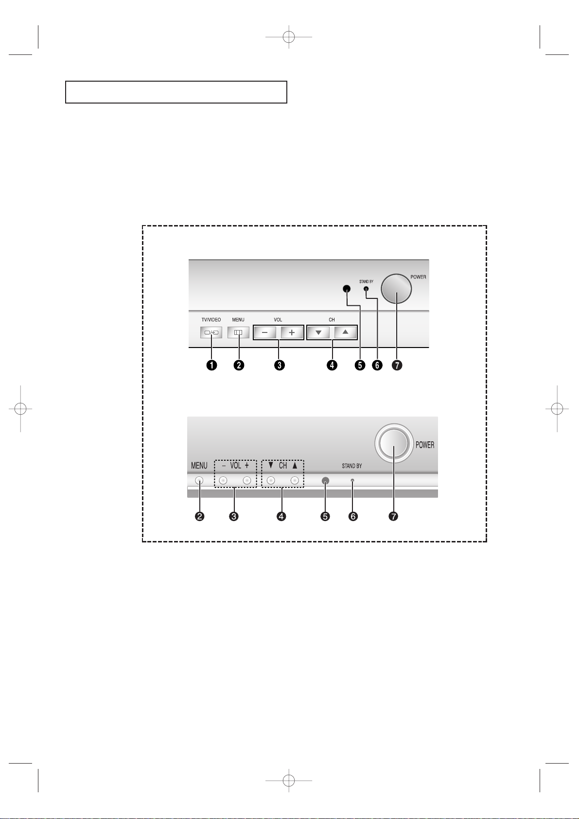
Familiarizing Yourself with The TV
Front Panel Buttons
The buttons on the front panel control your TV’s basic features, including the on-screen
menu. To use the more advanced features, you must use the remote control.
Œ
TV/VIDEO
Press to change between viewing TV programs
and signals from other components.
´
MENU
Press to see an on-screen menu of your TV's
features.
ˇ
VOL – , +
Press to increase or decrease the
volume. Also used to select items on the onscreen menu.
¨
CH ▼ and CH ▲
Press to change channels. Also press to highlight various items on the on-screen menu.
ˆ
STANDBY indicator
Lights up when you turn the power off.
Ø
Remote Control Sensor
Aim the remote control towards this spot on the
TV.
∏
POWER
Press to turn the TV on and off.
CL29A10 / CL34A10
CL29M6
KS7A(ET)Latin_ENG 12/7/03 4:53 PM Page 9
YOUR NEW TV
10
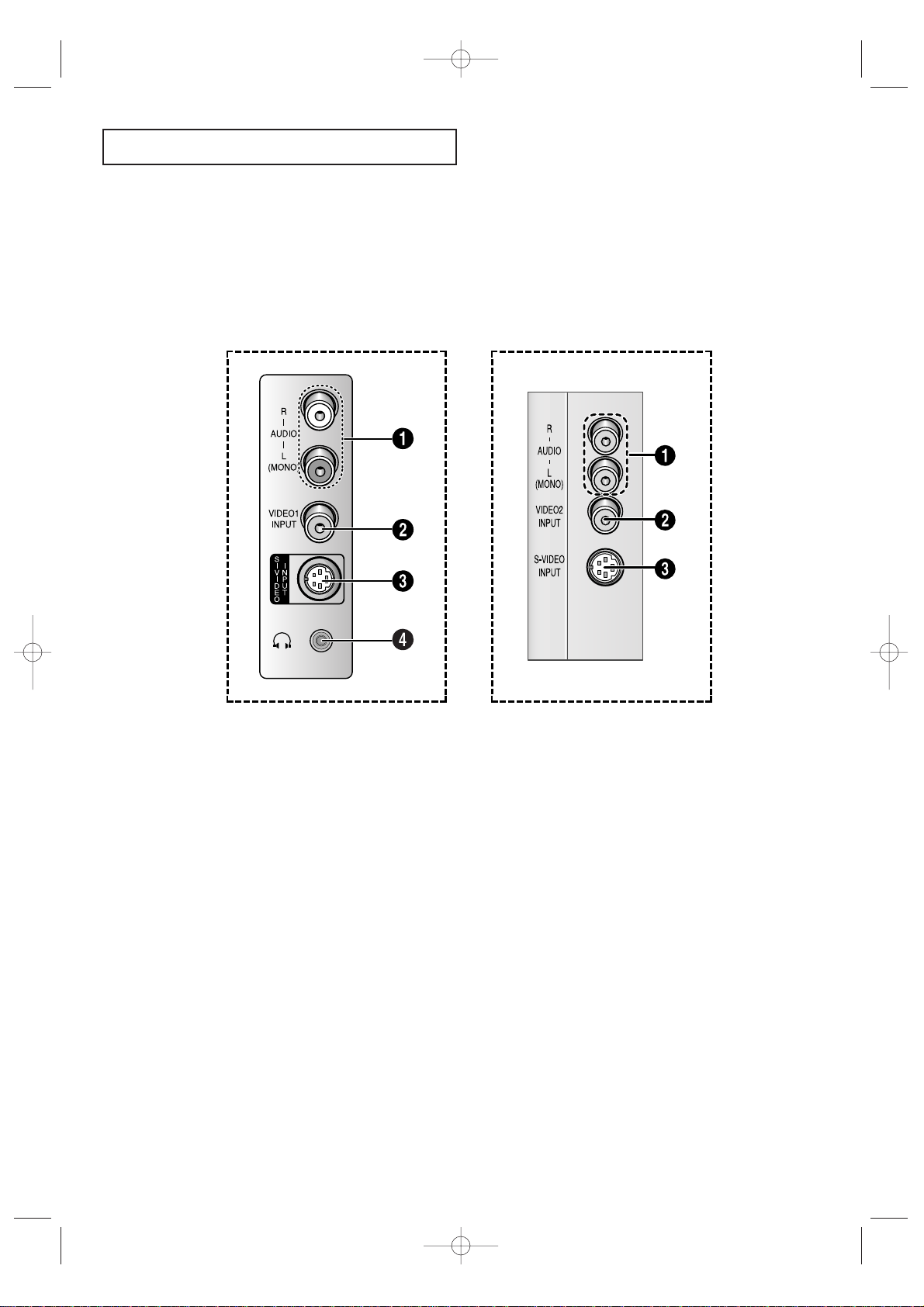
Side Panel Jacks
You can use the side panel jacks to connect an A/V component that is used only occasionally, such as a camcorder or video game. (For information on connecting equipment,
see pages 14-21.)
CL29A10 / CL34A10
CL29M6
Œ
AUDIO INPUT jacks
Used to connect the audio
signals from a camcorder or video game.
´
VIDEO INPUT jack
Used to connect a video signal from
a camcorder or video game.
ˇ
SUPER VIDEO INPUT jack
S-Video signal from an S-VHS VCR or DVD
player.
Note: In S-Video mode, Audio Output depends
what kind of audio input source is connected
to the side audio input jacks (AV1).
¨
HEADPHONE jack
Connect a set of external headphones to this
jack for private listening.
KS7A(ET)Latin_ENG 12/7/03 4:53 PM Page 10
YOUR NEW TV
11
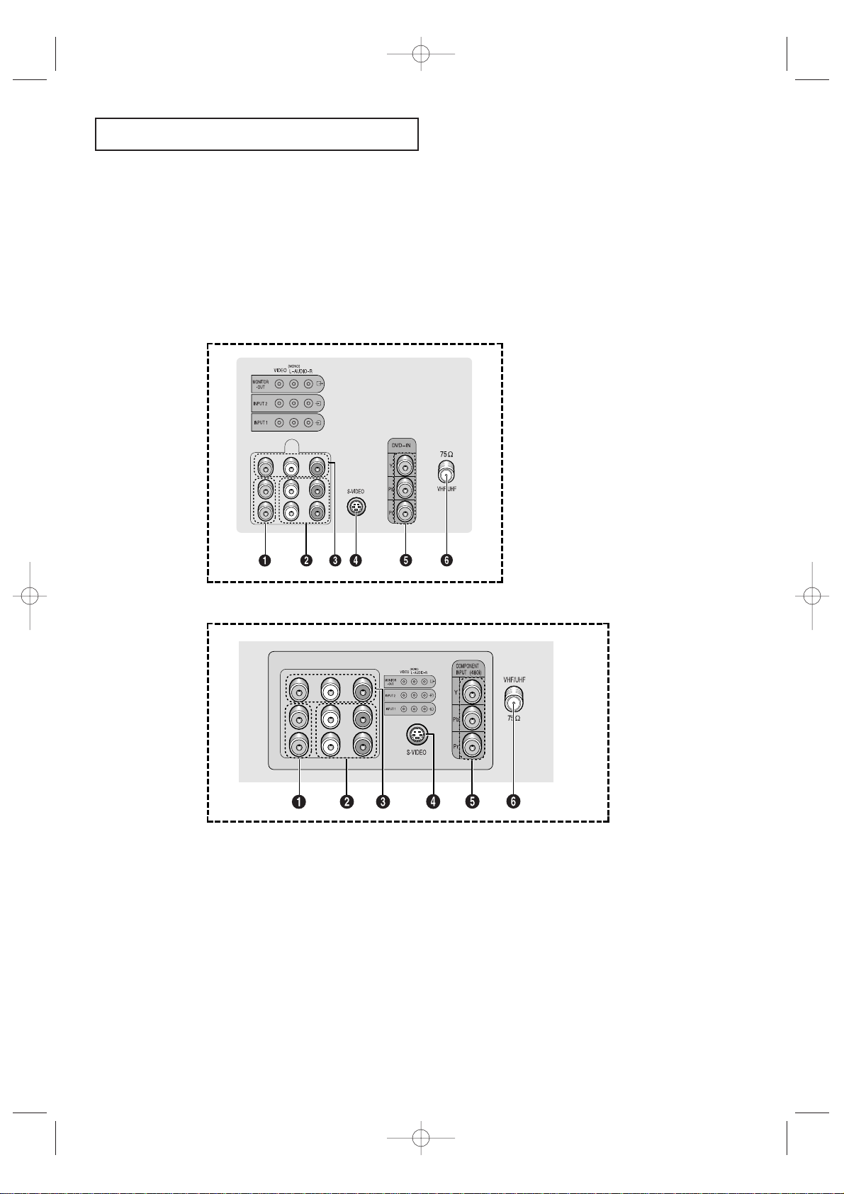
Rear Panel Jacks
Use the rear panel jacks to connect an A/V component that will be connected
continuously, such as a VCR or a DVD player.
Because there are two sets of input jacks, you can connect two different A/V
components (i.e., a VCR and a DVD, 2 VCRs, etc.)
For more information on connecting equipment, see pages 14 – 21.
Œ
VIDEO INPUT jack
Video signals from VCRs, laserdisc players and
similar devices.
´
AUDIO INPUTS (INPUT1
and 2)
/DVD AUDIO INPUTS
(INPUT 2)
Audio signals from VCRs, laserdisc players and
similar devices.
Use these jacks to connect the audio signals from
a DVD player when using the DVD video input
jacks. When not using the DVD jacks, these audio
jacks function as audio for Video 2 or S-VIDEO).
ˇ
AUDIO-VIDEO MONITOR
OUTPUT jacks
These audio-video signals are identical to A/V signals being displayed on the big screen. (Typically
used as the input signals for a recoding VCR.)
¨
SUPER VIDEO INPUT jack
S-Video signal from an S-VHS VCR or DVD player.
Note: In S-Video mode, Audio Output depends
what kind of audio input source is connected to
the side audio input jacks (AV1).
ˆ
DVD VIDEO INPUT jacks
(480i)
(CL29A10/CL34A10)
/
COMPONENT VIDEO INPUT
jacks
(CL29M6)
Connect video from a DVD player.
Note: Only black and white signals are output
from a monitor in DVD mode.
Ø
VHF/UHF
Connect to an antenna or to a cable TV system.
CL29M6
CL29A10 / CL34A10
KS7A(ET)Latin_ENG 12/7/03 4:53 PM Page 11
YOUR NEW TV
12
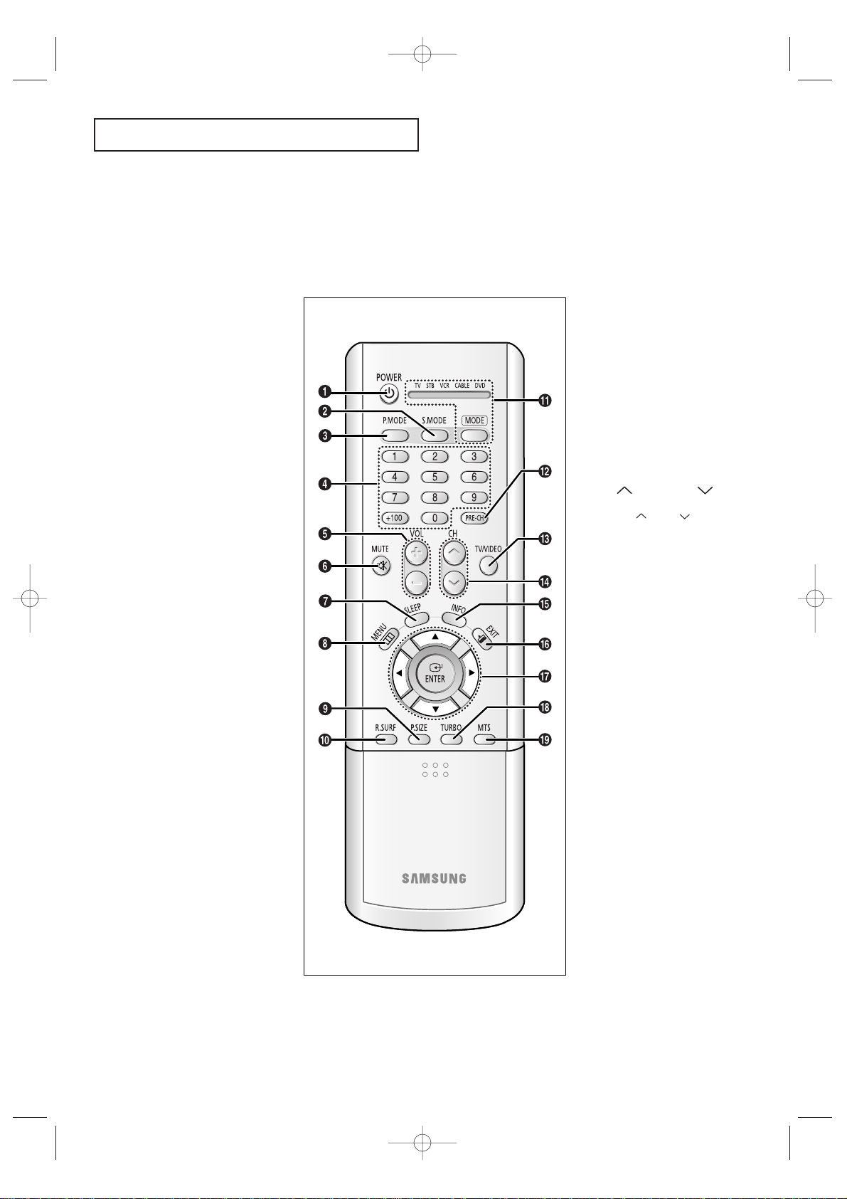
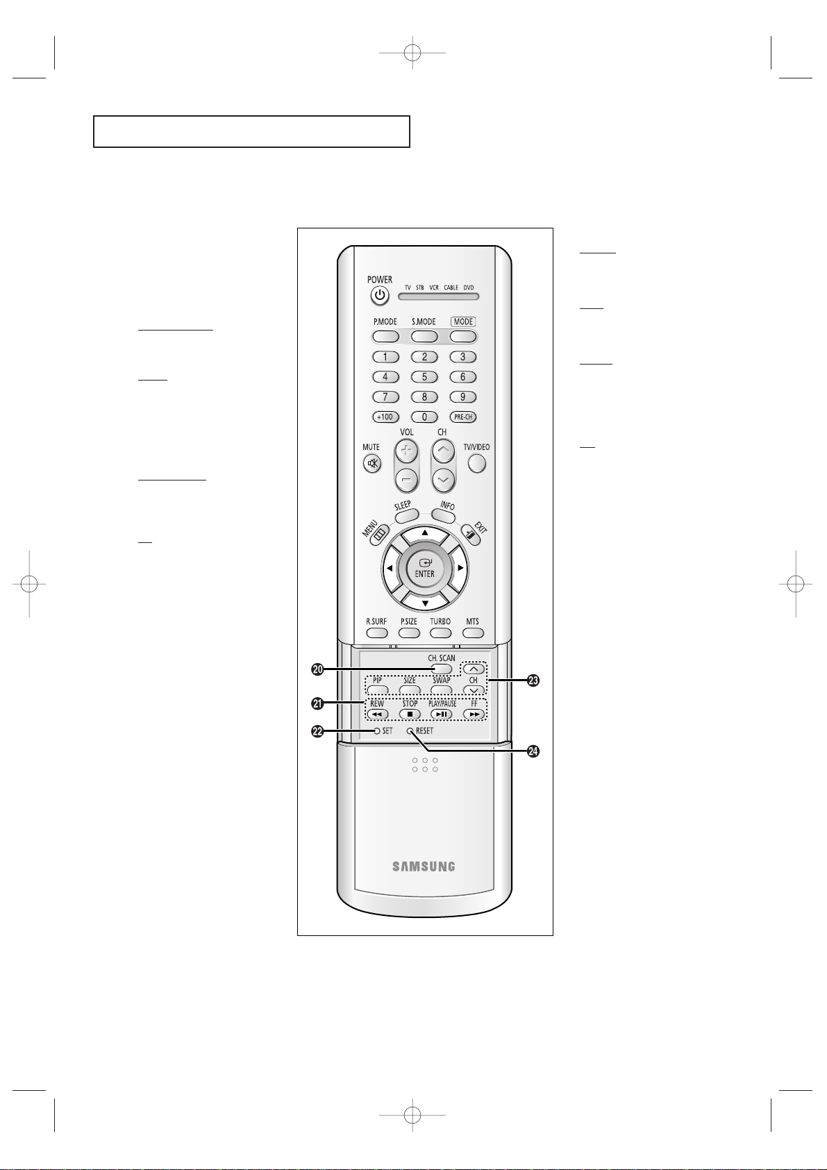
Remote Control
You can use the remote control up to about 23 feet from the TV. When using the remote,
always point it directly at the TV.
You can also use your remote control to operate your VCR and cable box. See page 42
for details.
Œ
POWER
Turns the TV on and off.
´
S.MODE
Adjust the TV sound by selecting
one of the preset factory settings
(or select your personal, customized sound settings).
ˇ
P. MODE
Adjust the TV picture by selecting
one of the preset factory settings
(or select your personal, customized picture settings).
¨
Number buttons
Press to select channels directly
on the TV.
+100
Press to select channels over 100.
For example, to select channel
121, press “+100”, then press “2”
and “1”.
ˆ
VOL -, VOL +
Press to increase or decrease the
volume.
Ø
MUTE
Press to temporarily cut off
the sound.
∏
SLEEP
Press to select a preset time
interval for automatic shutoff.
”
MENU
Displays the main on-screen
menu.
’
P.SIZE
Press to change the screen size.
Your choices are Normal, Zoom.
˝
R.SURF
Press the R.SURF button to automatically return to a preferred
channel after a user-preset time
delay.
Ô
MODE
Selects a target device to be controlled by the Samsung remote
control (i.e., TV, Set Top Box, VCR,
Cable box, or DVD).
PRE-CH
Tunes to the previous channel.
Ò
TV/VIDEO
Press to display all of the available
video sources (i.e., AV1, AV2,
S-VIDEO).
Ú
CH and CH
(Channel Up/Down)
Press CH or CH to change
channels.
Æ
INFO
Press to see the time, channel,
etc., on-screen. Also press to exit
(quit) the menu system.
ı
EXIT
Press to exit the menu.
˜
Up, Down, Left,
Right (▲,▼,œ,√)/
ENTER
Press to select highlight up, down,
left, or right. While using the onscreen menus, press ENTER to
activate (or change) a particular
item.
¯
TURBO
Press to select the turbo sound
On or Off.
˘
MTS (Multichannel
Television Stereo)
Press to choose stereo, mono or
Separate Audio Program (SAP
broadcast).
KS7A(ET)Latin_ENG 12/7/03 4:53 PM Page 12
YOUR NEW TV
13
Remote Control
¿
CH. SCAN
Press to memorize(scan) the
available channels.
¸
VCR(DVD, DVR or
STB) Controls
REW (Rewind)
Press to rewind a tape in your
VCR(DVD, DVR or STB).
STOP
Press this button to stop a tape
during play, record, rewind or
fast forward. If the button is
pressed during Full-Automatic
play, the function will be cancelled.
PLAY/PAUSE
Press the PLAY/PAUSE button to
play back prerecorded tapes or
pause the tape.
FF
Press to fast forward the tape in
your VCR(DVD, DVR or STB).
˛
SET
Use this button when you are
setting up your remote control to
operate your Set Top Box, VCR,
Cable box, or DVD.
◊
PIP Controls
PIP ON
Press this button to control the PIP
window.
SIZE
Press to make the PIP window
small window or large window.
SWAP
Exchanges the video signal that is
currently displayed on the main
screen with the signal in the PIP
window.
CH
Displays the available channels in
sequence (These buttons change
channels in the PIP window only).
±
RESET
If your remote control is not functioning properly, take out the batteries and press the reset button
for about 2~3 seconds. Re-insert
the batteries and try using the
remote control again.
KS7A(ET)Latin_ENG 12/7/03 4:53 PM Page 13
INSTALLATION
14
Chapter Two
INSTALLATION
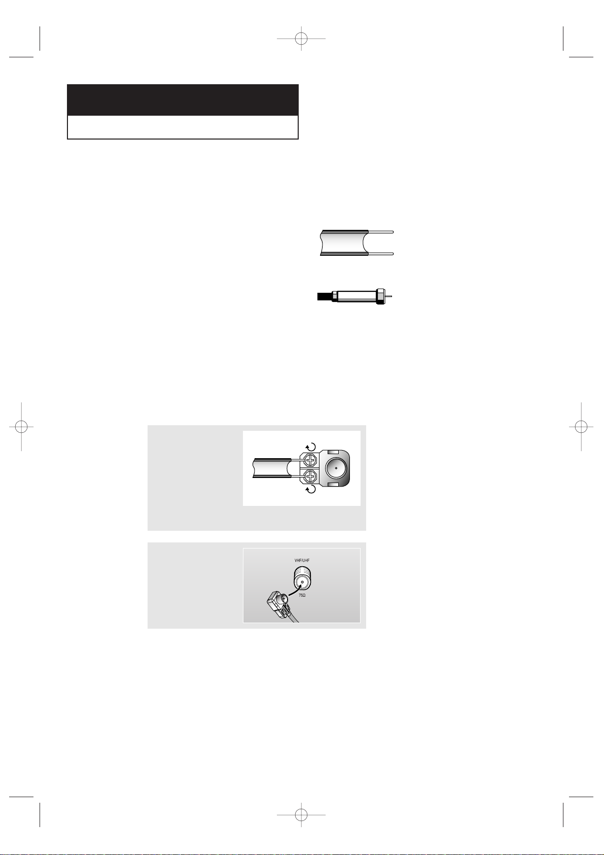
Connecting VHF and UHF Antennas
If your antenna has a set of leads that
look like this, see “Antennas with
300-ohm Flat Twin Leads,” below.
If your antenna has one lead that looks
like this, see “Antennas with 75-ohm
Round Leads,” on page 15.
If you have two antennas, see “Separate
VHF and UHF Antennas,” on page 15.
Antennas with 300-ohm Flat Twin Leads
If you are using an off-air antenna (such as a roof antenna or “rabbit ears”) that has
300-ohm twin flat leads, follow the directions below.
1
Place the wires from
the twin leads under
the screws on the 30075 ohm adaptor (not
supplied). Use a
screwdriver to tighten
the screws.
2
Plug the adaptor into
the VHF/UHF terminal
on the bottom of the
back panel.
KS7A(ET)Latin_ENG 12/7/03 4:53 PM Page 14
INSTALLATION
15
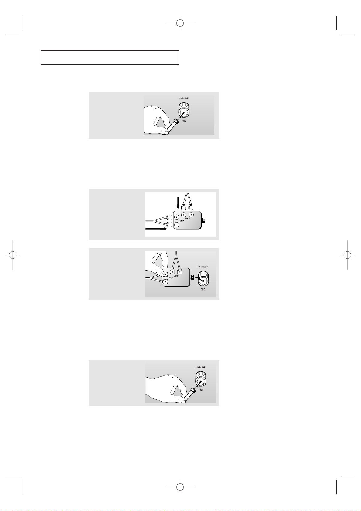
Connecting Cable TV
To connect to a cable TV system, follow the instructions below.
Cable without a Cable Box
▼
1
Plug the incoming cable
into the VHF/UHF
antenna terminal on
back of the TV.
Because this TV is
cable-ready, you do not need a
cable box to view unscrambled cable
channels.
2
Plug the combiner into
the VHF/UHF terminal
on the bottom of the
rear panel.
Separate VHF and UHF Antennas
If you have two separate antennas for your TV (one VHF and one UHF), you must
combine the two antenna signals before connecting the antennas to the TV. This
procedure requires a an optional combiner-adaptor (available at most electronics shops).
1
Connect both antenna
leads to the combiner.
Antennas with 75-ohm Round Leads
1
Plug the antenna lead
into the VHF/UHF
terminal on the bottom
of the back panel.
KS7A(ET)Latin_ENG 12/7/03 4:53 PM Page 15
INSTALLATION
16
Connecting to a Cable Box that Descrambles All Channels
▼
1
Find the cable that is
connected to the
ANTENNA OUT terminal
on your cable box.
This terminal might be labeled
“ANT OUT,” “VHF OUT,” or simply,
“OUT.”
2
Connect the other end
of this cable to the
VHF/UHF antenna
terminal on the back of
the TV.
Connecting to a Cable Box that Descrambles Some Channels
If your cable box descrambles only some channels (such as premium channels), follow the
instructions below. You will need a two-way splitter, an RF (A/B) switch, and four lengths of
coaxial cable. (These items are available at most electronics stores.)
▼
1
Find and disconnect the
cable that is connected
to the ANTENNA IN
terminal on your
cable box.
This terminal might be labeled
“ANT IN,” “VHF IN,” or simply,
“IN.”
2
Connect this cable to a
two-way splitter.
3
Connect a coaxial cable
between an OUTPUT
terminal on the splitter
and the IN terminal on
the cable box.
KS7A(ET)Latin_ENG 12/7/03 4:53 PM Page 16
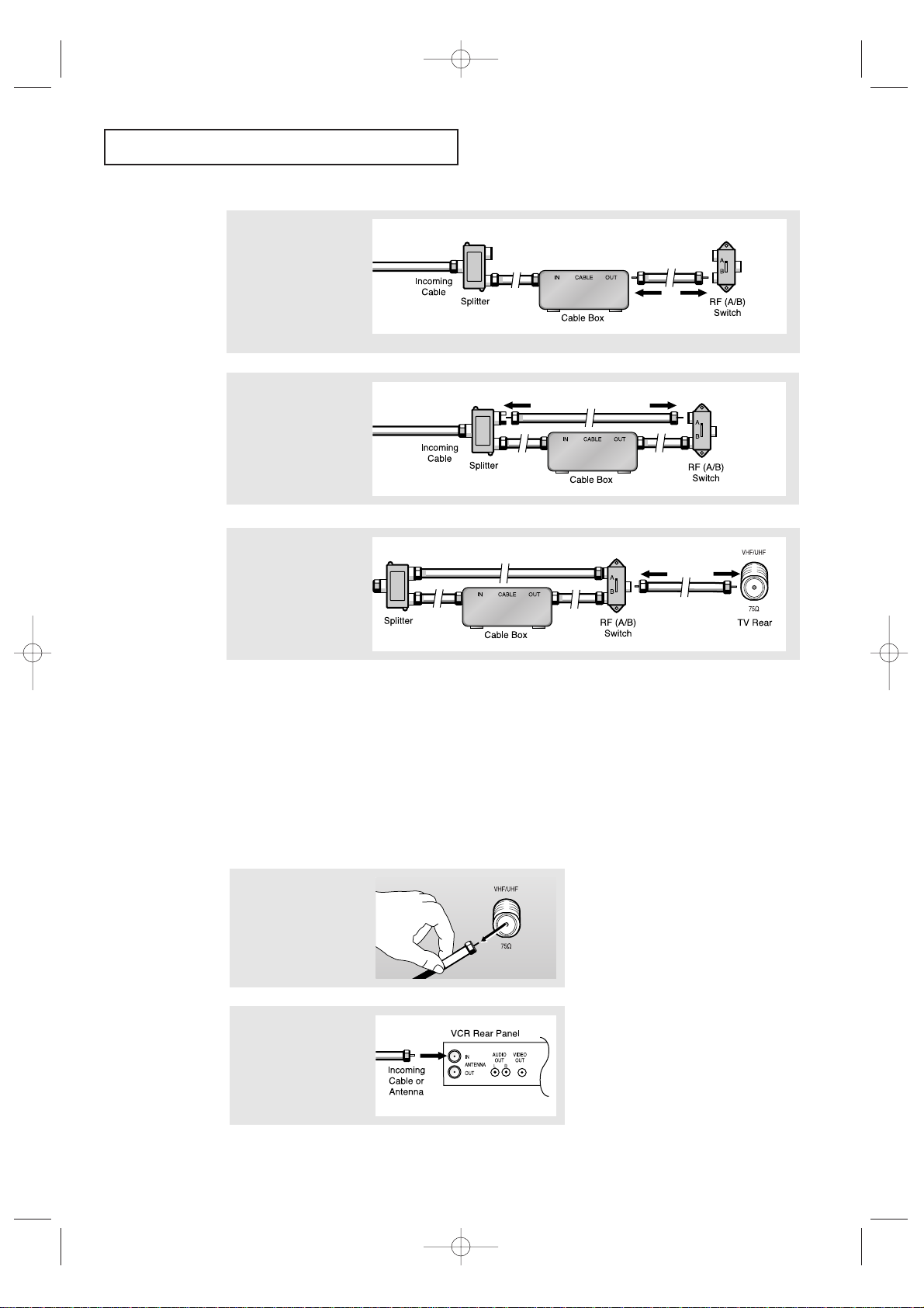
INSTALLATION
17
4
Connect a coaxial cable
between the ANTENNA
OUT terminal on the
cable box and the B–IN
terminal on the A/B
switch.
5
Connect another cable
between the other OUT
terminal on the splitter
and the A–IN terminal
on the RF (A/B) switch.
6
Connect the last coaxial
cable between the OUT
terminal on the RF (A/B)
switch and the VHF/UHF
terminal on the rear of
the TV.
Connecting a VCR
These instructions assume that you have already connected your TV to an antenna or a cable
TV system (according to the instructions on pages 14-16). Skip step 1 if you have not yet
connected to an antenna or a cable system.
After you’ve made this connection, set the A/B switch to the “A” position for normal viewing.
Set the A/B switch to the “B” position to view scrambled channels. (When you set the A/B
switch to “B,” you will need to tune your TV to the cable box’s output channel, which is usually channel 3 or 4.)
1
Unplug the cable or
antenna from the back
of the TV.
2
Connect the cable or
antenna to the
ANTENNA IN terminal
on the back of the VCR.
KS7A(ET)Latin_ENG 12/7/03 4:53 PM Page 17
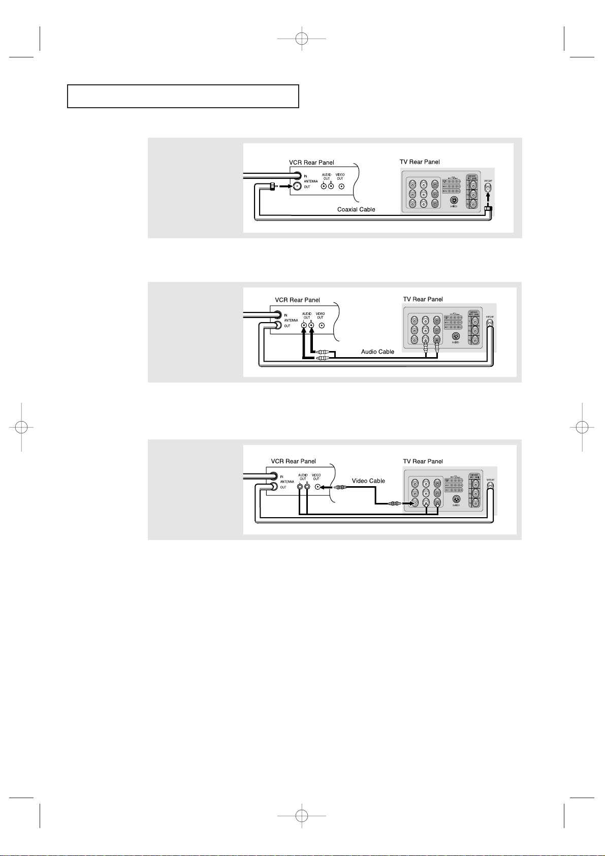
INSTALLATION
18
3
Connect a coaxial cable
between the ANTENNA
OUT terminal on the
VCR and the antenna
terminal on the TV.
4
Connect a set of audio
cables between the
AUDIO OUT jacks on the
VCR and the AUDIO
jacks on the TV.
5
Connect a video cable
between the VIDEO OUT
jack on the VCR and the
VIDEO jack on the TV.
Follow the instructions in “Viewing an External Signal Source” to view your VCR tape.
Note: This figure shows the Standard connector-jack panel. The actual configuration for
your TV may be different.
A coaxial cable is usually included with a VCR. (If not, check your local electronics
store).
If you have a “mono” (non-stereo) VCR, use the Y-connector (not supplied) to hook up
to the left and right audio input jacks of the TV. If your VCR is stereo, you must connect two cables.
KS7A(ET)Latin_ENG 12/7/03 4:53 PM Page 18
INSTALLATION
19
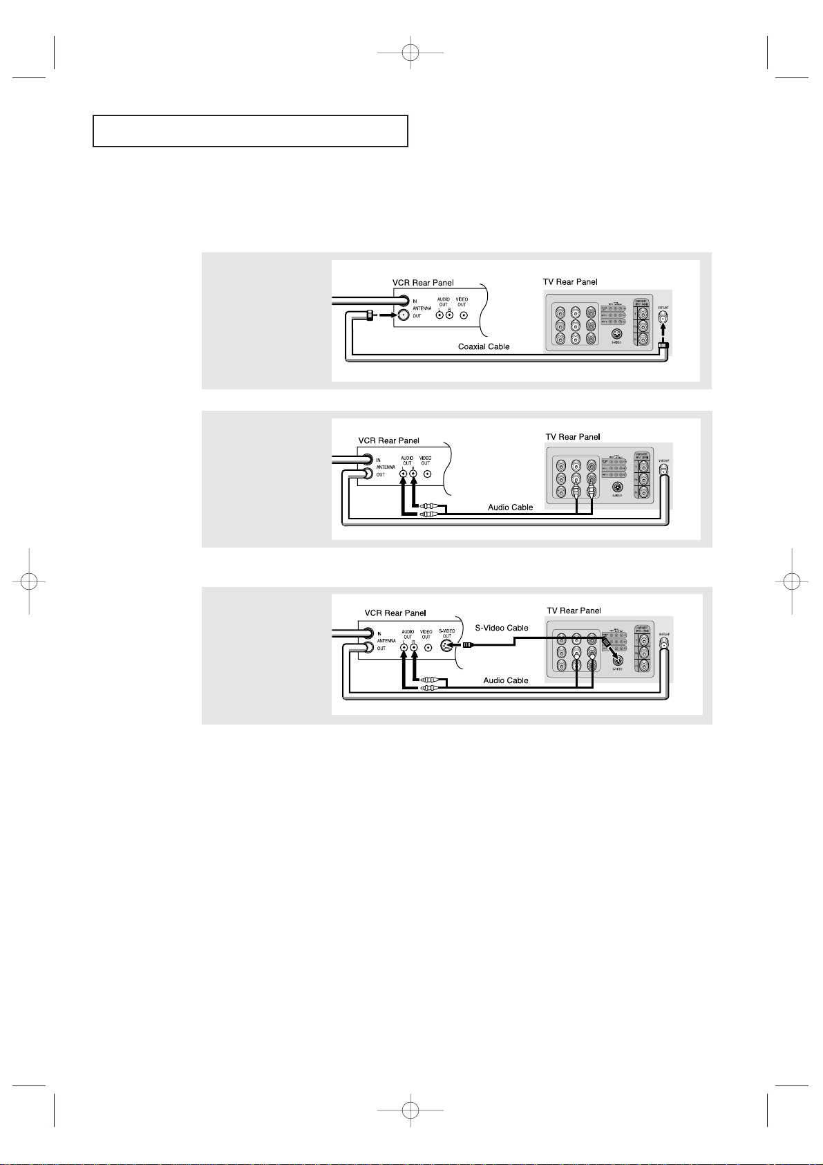
3
Connect an S-video
cable between the
S-VIDEO OUT jack on
the VCR and the
S-VIDEO INPUT
jack on the TV.
An S-video cable is usually included with an S-VHS VCR. (If not, check your local
electronics store.)
Note: This figure shows the Standard connector-jack panel. The actual configuration for
your TV may be different.
Make sure the jacks you are using are underneath the number “2.”
2
Connect a set of audio
cables between the
AUDIO OUT jacks on the
VCR and the 2 AUDIO
INPUT jacks on the TV.
1
To begin, follow steps
1–3 in the previous
section to connect the
antenna or cable to your
VCR and your TV.
Connecting an S-VHS VCR (Except models CT-29K3W/CT-29K5W)
Your Samsung TV can be connected to an S-Video signal from an S-VHS VCR. (This
connection delivers a better picture as compared to a standard VHS VCR.)
KS7A(ET)Latin_ENG 12/7/03 4:55 PM Page 19
INSTALLATION
20
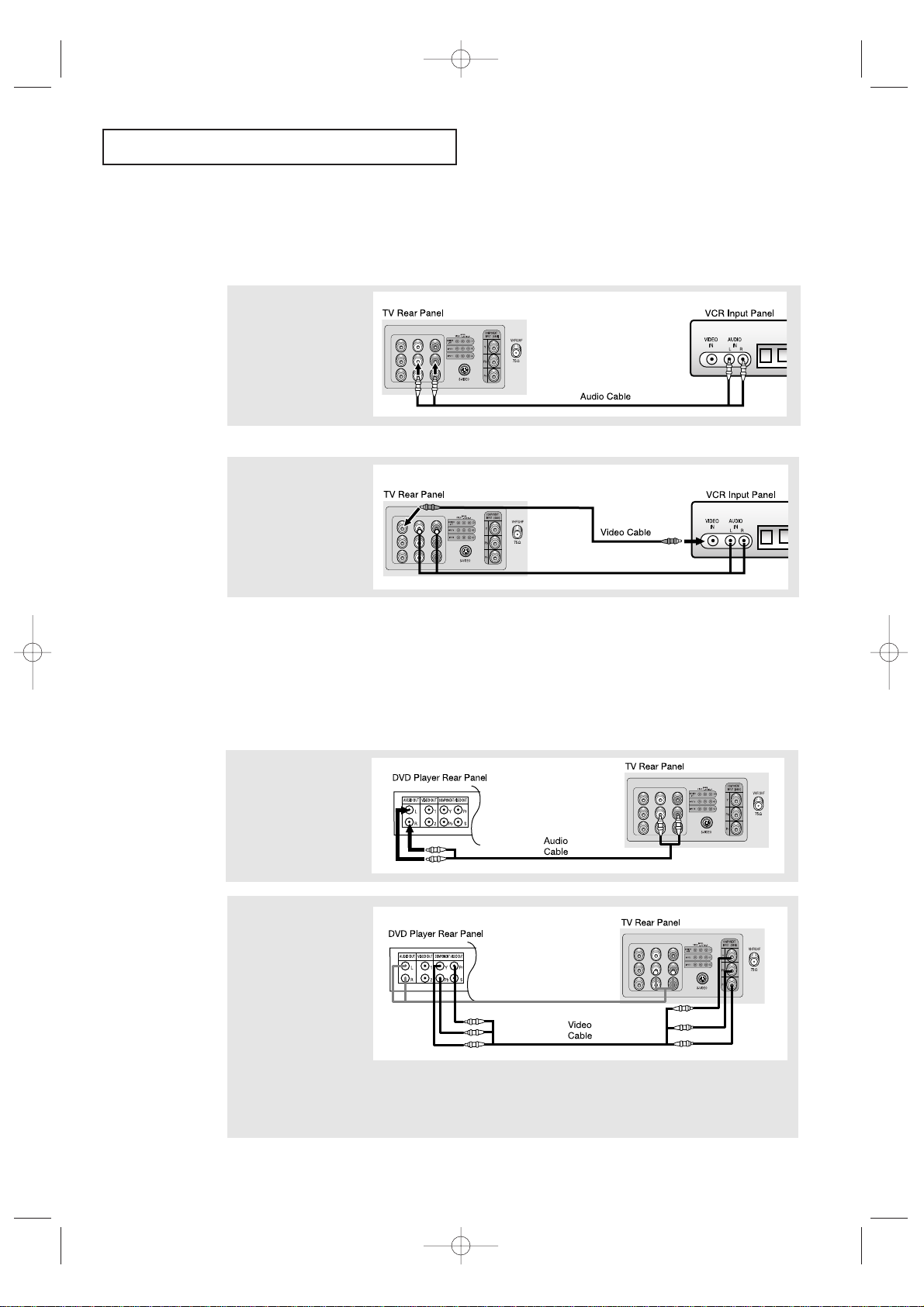
Connecting a Second VCR to Record from the TV
Your TV can send out signals of its picture and sound to be recorded by a second VCR.
To do this, connect your second VCR as follows:
1
Connect a set of audio
cables between the
AUDIO OUT jacks on the
TV and the AUDIO IN
jacks on the VCR.
2
Connect a video cable
between the VIDEO OUT
jack on the TV and the
VIDEO IN jack on the
VCR.
Refer to your VCR’s instructions for more information about how to record using this kind
of connection.
Note: This figure shows the Standard connector-jack panel. The actual configuration for
your TV may be different.
(The VCR input jacks might be either on the front or on back of the VCR.)
Connecting a DVD Player
The rear panel jacks on your TV make it easy to connect a DVD player to your TV.
1
Connect a set of audio
cables between the
AUDIO INPUT 2 jacks on
the TV and the AUDIO
OUT jacks on the DVD
player.
2
Connect a video cable
between the DVD-IN (Y,
Pb, Pr) jacks on the TV
and the DVD-OUT (Y, Pb,
Pr) jacks on the DVD
player.
To enable DVD viewing, connect video cables between the Y, Pb and Pr inputs on the TV and Y,Pb and Pr
outputs on the DVD player.
Note: For an explanation of Component video, see your DVD player's owner's manual.
Note: This figure shows the Standard connector-jack panel. The actual configuration for
your TV may be different.
KS7A(ET)Latin_ENG 12/7/03 5:05 PM Page 20

INSTALLATION
21
2
Connect an audio cable
between the AUDIO
OUTPUT jack on the
camcorder and the
AUDIO terminals on the
side of the TV.
3
Connect a video cable
between the VIDEO
OUTPUT jack on the
camcorder and the
VIDEO terminal on the
side of the TV.
1
Locate the A/V output
jacks on the camcorder.
They are usually found
on the side or back of
the camcorder.
Connecting a Camcorder
The side panel jacks on your TV make it easy to connect a camcorder to your TV. They allow
you to view the camcorder tapes without using a VCR. (Also see “Viewing an External Signal
Source” on page 40)
The audio-video cables shown here are usually included with a Camcorder. (If not, check
your local electronics store.) If your camcorder is stereo, you need to connect a set of two
cables.
Note: This figure shows the Standard connector-jack panel. The actual configuration for
your TV may be different.
KS7A(ET)Latin_ENG 12/7/03 5:21 PM Page 21

INSTALLATION
22
▼
3
Replace the cover.
Remove the batteries and store
them in a cool, dry place if you won’t
be using the remote control for a
long time.
The remote control can be used up
to about 23 feet from the TV.
(Assuming typical TV usage, the batteries last for about one year.)
▼
2
Install two AAA size
batteries.
Make sure to match the “+” and
“
–” ends of the batteries with the
diagram inside the compartment.
Installing Batteries in the Remote Control
1
Slide the cover out completely.
KS7A(ET)Latin_ENG 12/7/03 5:12 PM Page 22
OPERATION
23
OPERATION
Chapter Three
OPERATION
1
Press the POWER button
on the remote control.
The message “Plug &
Play” is displayed.
It flickers for a little while
and then the “Language”
menu is automatically
displayed.
Turning the TV On and Off
Press the POWER button on the remote control.
You can also use the POWER button on the front panel.
Plug & Play Feature
When the TV is initially powered On, five basic customer settings proceed automatically
and subsequently: Setting the language, Video signal source, Ant. input check, Auto
program, and Clock.
Plug & Play
3
Press the
√√
button to
select the desired video
signal source.
Press the ENTER button to
enter the video signal
source, and then the
“Ant Input check” is
automatically displayed.
Make sure that the antenna is connected to the TV.
4
Press the ENTER button
and then the “Auto Store”
is automatically displayed.
2
Press the √√button to
select the desired
language.
Press the ENTER button to
enter the language, and
then the “Channel” menu
is automatically displayed.
Ant Input check
Auto Store Exit
Auto Store
Air 3
Enter Skip
Start
Move Enter Return
Setup
Time
√√
Plug & Play
√√
Captions
√√
Language : English
▼
More
KS7A(ET)Latin_ENG 12/7/03 5:12 PM Page 23

OPERATION
24
6
Press the ENTER button
and then press the œœor
√√
button to move the hour or
minute. Set the hour or
minute by pressing the ▲
or ▼ button. (refer to
“Setting the Clock” on
page 33.)
7
When you have finished,
press the MENU button.
The message “Enjoy your
watching..” is displayed.
8
If you want to reset this
feature
(1)Press the MENU
button.
(2)Press the ▼ button to
select the “Setup”,
then press the ENTER
button.
(3)Press the ▼ button
to select “Plug & Play”,
then press the ENTER
button.
The message “Plug &
Play” is displayed.
Note: Plug & Play feature doesn’t work when in the AV
mode.
Enjoy your watching..
Move Adjust Return
Time
Clock 12 : 00 am
On Time - - : - - am Off
Off Time - - : - - am Off
Sleep Timer : Off
On Time Volume : 10
Move Enter Return
Setup
Time
√√
Plug & Play
√√
Captions
√√
Language : English
▼
More
5
Press the ENTER button to
start "Auto Store" or press
the MENU button to skip.
(refer to “Auto program”
on page 29.) The TV will
begin memorizing all of
the available channels.
Auto Store
Air 7
Enter Skip
Stop
KS7A(ET)Latin_ENG 12/7/03 5:12 PM Page 24

OPERATION
25
Viewing the Display
The display identifies the current channel and the status
of certain audio-video settings.
▼
The on-screen displays
disappear after ten seconds.
Viewing the Menus and On-Screen Displays
Viewing the Menus
▼
1
With the power on, press
the MENU button.
The main menu appears
on the screen. Its left side
has five icons: Input,
Picture, Sound, Channel,
Setup.
The on-screen menus disappear
from the screen after thirty seconds.
▼
You can also use the MENU,
CHANNEL, and VOLUME buttons
on the control panel of the TV to
make selections.
1
Press the INFO button.
The on-screen display
shows any or all of the
following:
Active channel, the
channel label, signal,
video mode, audio
mode, MTS, and the
current time.
2
Use the ▲ and ▼ buttons to highlight one of the 5 icons.
Then press the ENTER button to access the icon’s sub-menu.
3
Press the EXIT button to exit.
Move Enter Exit
Source List : TV
√√
Edit Name
√√
Input
Air 10
Signal : Mono
Mode : Custom
Mode : Custom
MTS : Mono
12 : 00 am
KS7A(ET)Latin_ENG 12/7/03 5:12 PM Page 25

OPERATION
26
Selecting a Menu Language
1
Press the MENU button to
display the menu.
Press the ▼ button to
select “Setup”, then press
the ENTER button.
3
Press the
√√
button to
select the appropriate
language: “English”,
“Español” or “Português”.
4
Press the EXIT button to
exit.
Move Enter Return
Setup
Time
√√
Plug & Play
√√
Captions
√√
Language : English
▼
More
2
Press the ▼ button to
select “Language”, then
press the ENTER button.
Move Adjust Return
Configuración
Tiempo
√√
Plug & Play
√√
Subtítulo
√√
Idioma : Español
▼
Más
Move Enter Return
Setup
Time
√√
Plug & Play
√√
Captions
√√
Language : English
▼
More
KS7A(ET)Latin_ENG 12/7/03 5:12 PM Page 26

OPERATION
27
Memorizing the Channels
Your TV can memorize and store all of the available channels for both “off-air” (antenna)
and cable channels. After the available channels are memorized, use the CH and
CH buttons to scan through the channels. This eliminates the need to change channels by entering the channel digits. There are three steps for memorizing channels:
selecting a broadcast source, memorizing the channels (automatic) and adding and deleting channels (manual).
Selecting the Video Signal-source
Before your television can begin memorizing the available channels, you must specify the
type of signal source that is connected to the TV (i.e., an antenna or a cable system).
1
Press the MENU button to
display the menu.
Press the ▼ button to
select “Channel”, then
press the ENTER button
2
Press the ▼ button to
select “Air/CATV”, then
press the ENTER button
Note: STD, HRC and IRC identify various types of cable
TV systems. Contact your local cable company to identify
the type of cable system that exists in your particular area.
At this point the signal source has been selected. Proceed
to “Storing Channels in Memory” (next page).
Move Enter Return
Channel
Auto Program
√√
Add/Delete : Deleted
√√
Air/CATV : Air
Labeling :
----
LNA : Off
√√
Move Enter Return
Channel
Auto Program
√√
Add/Delete : Deleted
√√
Air/CATV : Air
Labeling :
----
LNA : Off
√√
3
Repeatedly press the
√√
button to cycle
through these choices:
“Air” (antenna) “STD”,
“HRC” or “IRC” (all cable
TV)
Press the EXIT button to
exit.
Move Adjust Return
Channel
Auto Program
√√
Add/Delete : Deleted
√√
Air/CATV : STD
Labeling :
----
LNA : Off
√√
KS7A(ET)Latin_ENG 12/7/03 5:12 PM Page 27

OPERATION
28
3
Press the ENTER button
to start "Auto Store".
The TV will begin
memorizing all of the
available channels.
After all the available
channels are stored,
the Auto program menu
reappears. Press the
MENU button to skip
and press the
ENTER
button to stop.
Storing Channels in Memory (Automatic Method)
▼
The TV automatically cycles
through all of the available channels
and stores them in memory. This
takes about one to two minutes.
2
Press the ▲ button to
select “Auto program”
and then press the ENTER
button.
The “Auto Store” is
automatically displayed.
1
First, select the correct
signal source (Air, STD,
HRC, IRC). See steps 1~3
on previous page.
Move Adjust Return
Channel
Auto Program
√√
Add/Delete : Deleted
√√
Air/CATV : Air
Labeling :
----
LNA : Off
√√
Move Enter Return
Channel
Auto Program
√√
Add/Delete : Deleted
√√
Air/CATV : Air
Labeling :
----
LNA : Off
√√
Auto Store
Air 3
Enter Skip
Start
Auto Store
Air 5
Enter Skip
Stop
KS7A(ET)Latin_ENG 12/7/03 5:12 PM Page 28

OPERATION
29
Adding and Erasing Channels (Manual Method)
First, press the CH or CH button or the number buttons
to select the channel you want to add or delete.
1
Press the MENU button to
display the menu.
Press the ▼ button to
select “Channel”, then
press the ENTER button.
2
Press the ▲ or ▼ button
to select “Add/Delete”,
then press the ENTER
button.
3
Press the ▲ or ▼ button
to select “Added” or
“Deleted” then press the
ENTER button.
Press the EXIT button to
exit.
Move Enter Return
Channel
Auto Program
√√
Add/Delete : Deleted
√√
Air/CATV : Air
Labeling :
----
LNA : Off
√√
Move Enter Return
Channel
Auto Program
√√
Add/Delete : Deleted
Air/CATV : Air
Labeling :
----
LNA : Off
√√
Deleted
Added
Move Enter Return
Channel
Auto Program
√√
Add/Delete : Deleted
√√
Air/CATV : Air
Labeling :
----
LNA : Off
√√
KS7A(ET)Latin_ENG 12/7/03 5:12 PM Page 29

OPERATION
30
Changing Channels
Using the Channel Buttons
1
Press the CH or CH button to change channels.
When you press CH or CH , the TV changes channels in sequence. You will see all the
channels that the TV has memorized. (The TV must have memorized at least three channels.)
You will not see channels that were either erased or not memorized.
Directly Accessing Channels
Use the number buttons to quickly tune to any channel.
1
Press the number buttons to go directly to a channel. For example,
to select channel 27, press “2” then “7”. The TV will change channels when you press the second number.
To View Memorized Channel
1
Press the CH. SCAN button
or the Channel button.
Only the memorized
channels are chosen.
When you use the number buttons, you can directly select channels that were either erased
or not memorized.
To select a channel over 100, press the
+100 button. (For channel 122, press “+100” then “2”
then “2”.)
To change to single-digit channels (0–9) faster, press “0” before the single digit.
(For channel “4” press “0” then “4”.)
Using the PRE-CH Button to select the Previous Channel
1
Press the PRE-CH button.
The TV will switch to the
last channel viewed.
▼
To quickly switch between two
channels that are far apart, tune to
one channel, then use the number
button to select the second channel.
Then, use the PRE-CH button to
quickly alternate between them.
KS7A(ET)Latin_ENG 12/7/03 5:12 PM Page 30

OPERATION
31
Labeling the Channels
Use this feature to assign an easy-to-remember label to any channel (i.e., “CBS”,
“ESPN”, “PBS2”, CNN1”, etc.) A label consists of four fields, where each field is a letter,
a number, “*”, or a blank. When the INFO button is pressed, the channel label will
appear next to the channel number.
1
Press CH or CH to
tune to the channel that
will be labeled.
2
Press the MENU button to
display the menu.
Press the ▼ button to
select “Channel”, then
press the ENTER button.
3
Press the ▼ button to
select “Labeling”.
Press
√√
to begin labeling.
The left-most field will be
highlight.
(Each label has four fields.
See top paragraph.)
4
Press the ▲ or ▼ button
to select a letter, a number,
“*”, or a blank.
(Pressing ▲ button results
in this sequence: A, B,...Z,
*, blank, 0, 1, ...9).
▼
Note: You cannot select
“Labeling” in the AV mode.
5
Press
√√
button to switch
to the next field, which will
be highlight.
Select a second letter or
digit using the ▲ or ▼
button, as above.
Repeat the process to
select the last two digits.
Press the EXIT button to
exit.
Air 11
Move Adjust Return
Channel
Auto Program
√√
Add/Delete : Deleted
√√
Air/CATV : Air
Labeling :
A
---
LNA : Off
√√
Move Adjust Return
Channel
Auto Program
√√
Add/Delete : Deleted
√√
Air/CATV : Air
Labeling :
P
---
LNA : Off
√√
Move Adjust Return
Channel
Auto Program
√√
Add/Delete : Deleted
√√
Air/CATV : Air
Labeling :
PBS2
LNA : Off
√√
Move Enter Exit
Channel
Auto Program
√√
Add/Delete : Deleted
√√
Air/CATV : Air
Labeling :
----
LNA : Off
√√
KS7A(ET)Latin_ENG 12/7/03 5:12 PM Page 31

OPERATION
32
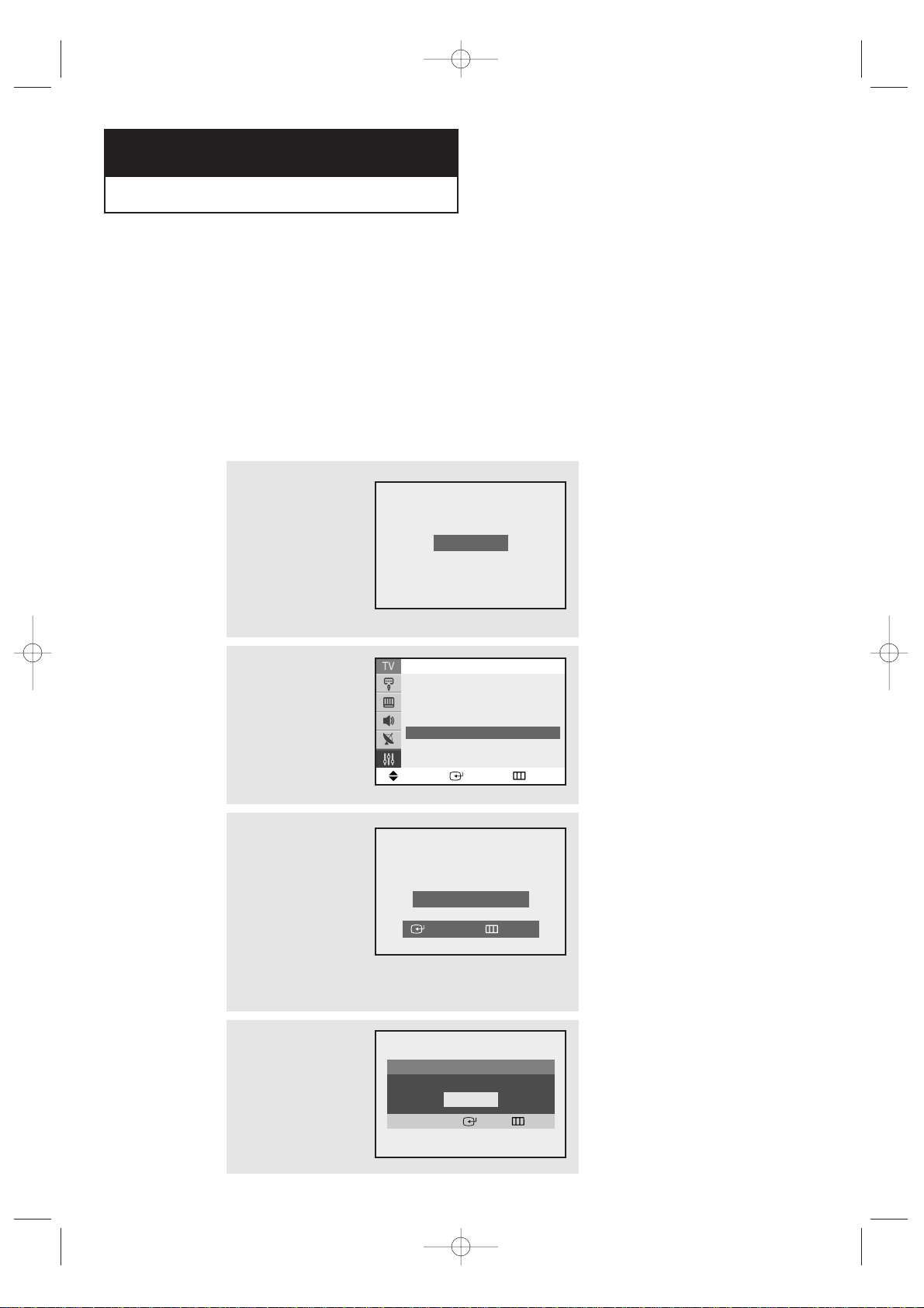
Adjusting the Volume
Press VOL + or – VOL – to increase or decrease the volume.
Using the MUTE Button
At any time, you can temporarily cut off the sound using the MUTE button.
1
Press MUTE and the sound
cuts off.
The word “Mute” will
appear in the lower-left
corner of the screen.
2
To turn mute off, press MUTE again, or simply press either the
VOL + or VOL – button.
MUTE
KS7A(ET)Latin_ENG 12/7/03 5:12 PM Page 32

OPERATION
33
Setting the Clock
1
Press the MENU button to
display the menu.
Press the ▼ button to
select “Setup”, then press
the ENTER button.
▼▼
When selecting the hours, be sure
to select the proper time of day (am or
pm).
You can change the hours by pressing
the
▲ or ▼ button repeatedly (or by
holding down either of these buttons).
3
After the hour is entered,
Press the √√button.
(at this point the minutes
digits will be highlighted).
Press the ▲ or ▼ button
to select the correct
minutes.
After selecting the correct minutes,
press the √√button.
Press the EXIT button to exit.
The time will appear every time
you press the INFO button.
Move Enter Return
Setup
Time
√√
Plug & Play
√√
Captions
√√
Language : English
▼
More
Move Adjust Return
Time
Clock 09: - - am
On Time - - : - - am Off
Off Time - - : - - am Off
Sleep Timer : Off
On Time Volume : 10
Move Adjust Return
Time
Clock 09: 30 am
On Time - - : - - am Off
Off Time - - : - - am Off
Sleep Timer : Off
On Time Volume : 10
2
Press the ENTER button.
Press the ENTER button
again to select the hours.
(the hours digits will be
highlighted).
Press the ▲ or ▼ button
repeatedly until the
correct hour appears.
KS7A(ET)Latin_ENG 12/7/03 5:12 PM Page 33

OPERATION
34
1
Press the MENU button to
display the menu.
Press the ▼ button to
select “Picture”, then
press the ENTER button.
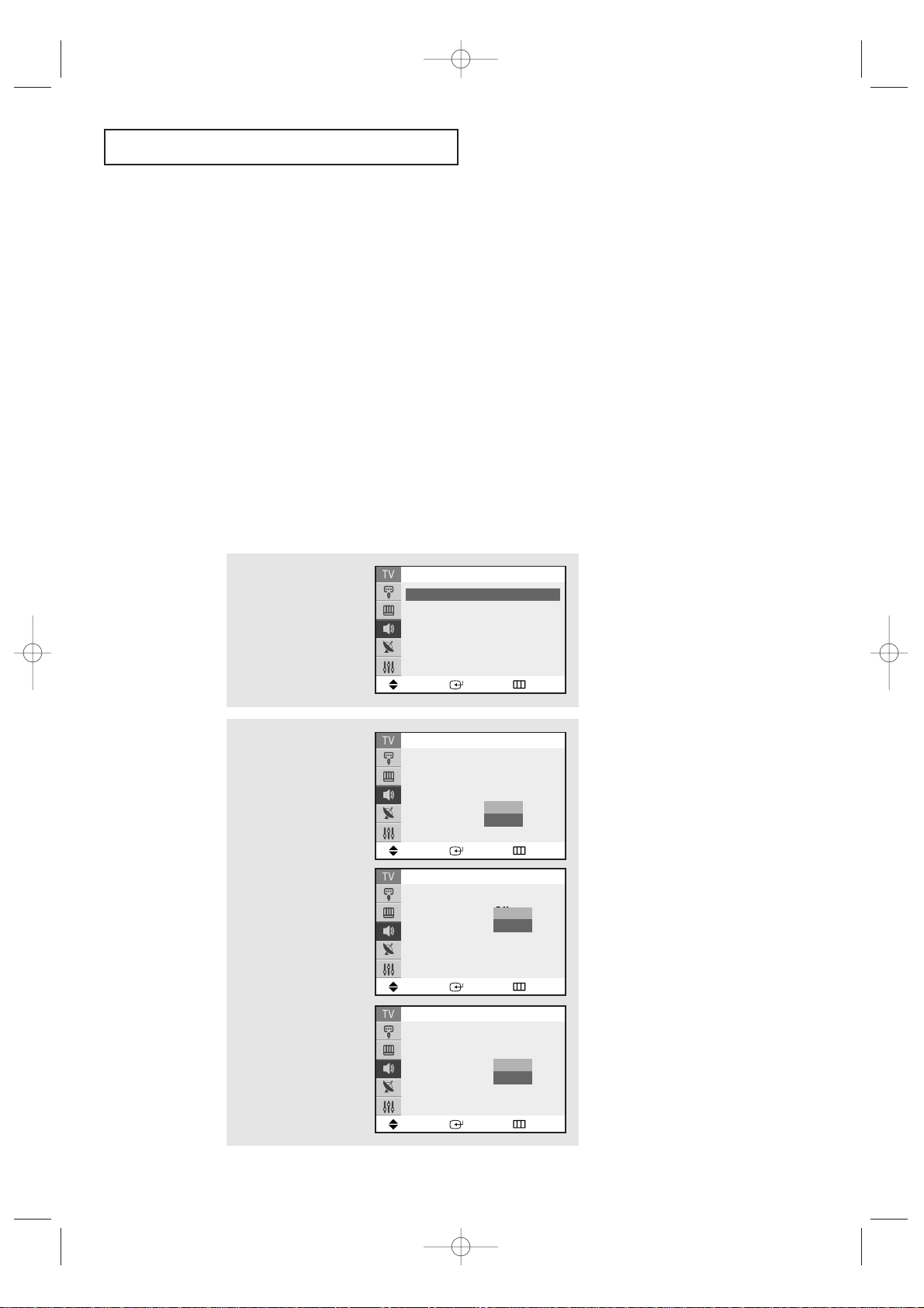
Customizing the Picture
You can use the on-screen menus to change the Contrast, Brightness, Sharpness, Color,
Tint and according to personal preference. (Alternatively, you can use one of the
“Automatic” settings. See next page.)
4
Press the œœor√√button
to increase or decrease
the value of a particular
item.
For example, if you select
“Brightness,” pressing
the √√button increases it.
Press the
EXIT button to
exit.
▼
After adjusting an item, the gauge
will automatically disappear (after
about 3 seconds).
2
Press the ▼ button to
select “Custom”, then
press the ENTER button.
(The words Contrast,
Brightness, Sharpness,
Color and Tint will appear
on the screen.)
3
Press the ▲ or ▼ button
to select a particular
item, then press the
ENTER button.
Move Enter Return
Mode : Custom
√√
Custom
√√
Color tone : Normal
√√
Size : Normal
√√
▼
More
Picture
Move Enter Return
Contrast : 100
Brightness : 45
Sharpness : 75
Color : 55
Tint : G50 R50
Custom
Move Enter Return
Mode : Custom
√√
Custom
√√
Color tone : Normal
√√
Size : Normal
√√
▼
More
Picture
Brightness 55
Move Adjust Return
KS7A(ET)Latin_ENG 12/7/03 5:12 PM Page 34

OPERATION
35
Using Automatic Picture Settings
Your TV has three automatic picture settings (“Dynamic”, “Standard” and “Movie” ) that
are preset at the factory. You can activate either Dynamic, Standard, Movie or Custom
by pressing the P.MODE button (or by making a selection from the menu). Or, you can
select “Custom” which automatically recalls your personalized picture settings.
• Choose Dynamic for viewing the TV during the day or when there is
brightlight in the room.
• Choose
Standard for the standard factory settings.
• Choose
Movie when viewing the movie.
• Choose
Custom if you want to adjust the settings accordings to personal
preference (see “Customizing the Picture”, page 34).
1
Press the MENU button to
display the menu.
Press the ▼ button to
select “Picture”, then
press the ENTER button.
2
Press the ENTER button
again.
Press the ▲ or ▼ button
to select the “Dynamic”,
“Standard” “Movie” or
“Custom” picture setting,
then press the ENTER
button.
Press the EXIT button to
exit.
Move Enter Return
Mode : Custom
√√
Custom
√√
Color tone : Normal
√√
Size : Normal
√√
▼
More
Picture
Move Enter Return
Mode : Custom
Custom
√√
Color tone : Normal
√√
Size : Normal
√√
▼
More
Picture
Dynamic
Standard
Movie
Custom
KS7A(ET)Latin_ENG 12/7/03 5:13 PM Page 35
OPERATION
36
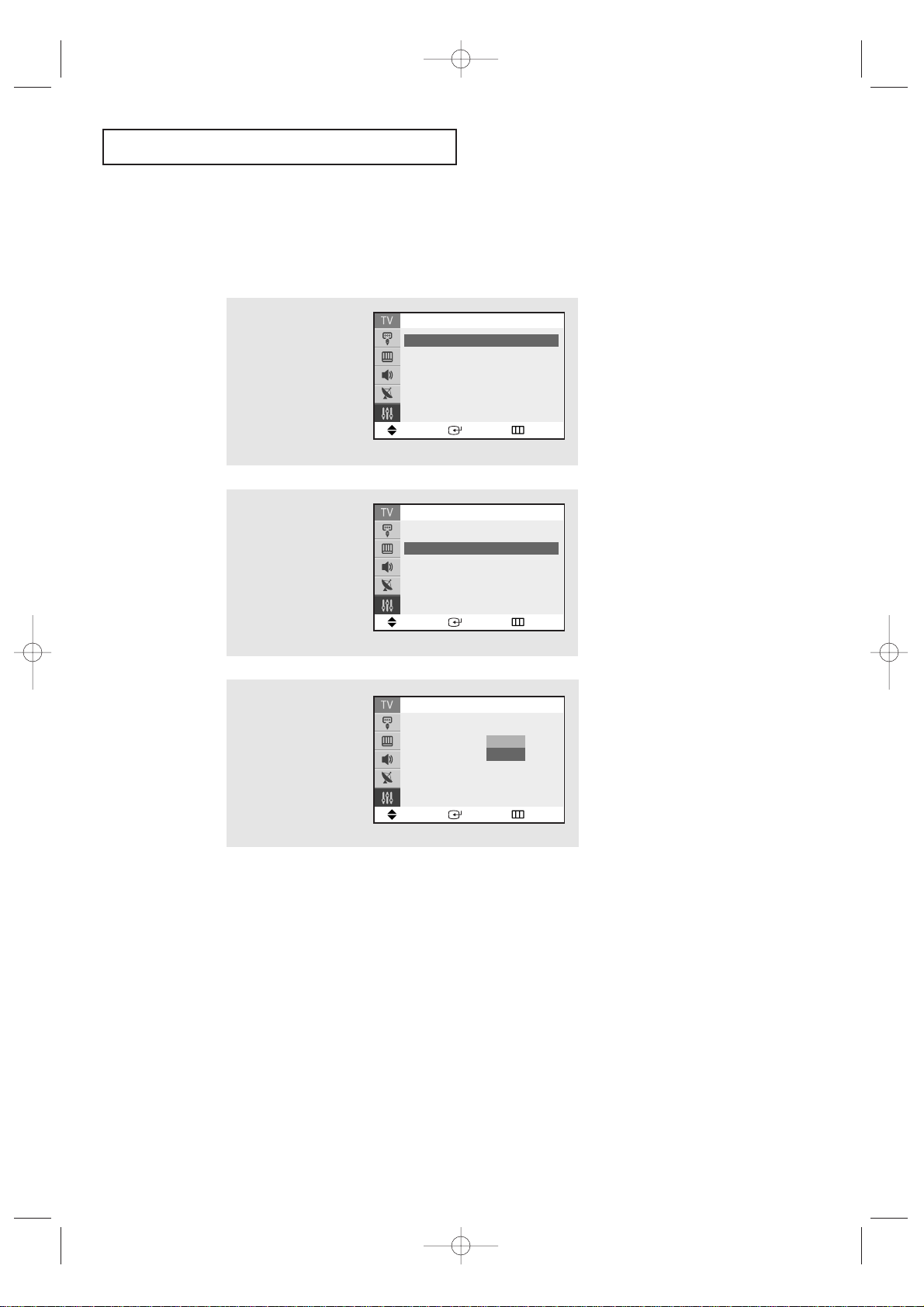
2
Press the ▼ button to
select “Custom”, then
press the ENTER button.
1
Press the MENU button to
display the menu.
Press the ▼ button to
select the “Sound”, then
press the ENTER button.
Customizing the Sound
You can use the on-screen menus to adjust the bass, treble, and balance according
to individual preference. (Alternatively, you can use one of the “automatic” settings.
See next page.)
3
Press the ▲ or ▼ button
to select a particular
item, then press the
ENTER button.
Move Enter Return
Sound
Mode : Custom
√√
Custom
√√
MTS : Mono
√√
Auto Volume : Off
√√
▼
More
Move Enter Return
Sound
Mode : Custom
√√
Custom
√√
MTS : Mono
√√
Auto Volume : Off
√√
▼
More
Move Enter Return
Custom
Bass : 50
Treble : 50
Balance : L 50 R 50
4
Press the œœor√√button
to increase or decrease
the value of a particular
item.
For example, if you select
“Treble,” pressing the
√√
button increases it.
Press the EXIT button to
exit.
Treble 55
Move Adjust Return
KS7A(ET)Latin_ENG 12/7/03 5:13 PM Page 36

OPERATION
37
Using Automatic Sound Settings
Your TV has four automatic sound settings (“Standard,” “Music,” “Movie,” and “Speech”)
that are preset at the factory. You can activate either Standard, Music, Movie or Speech
by pressing the S.MODE button (or by making a selection from the menu). Or, you can
select “Custom,” which automatically recalls your personalized sound settings.
• Choose Standard for the standard factory settings.
• Choose
Music when watching music videos or concerts.
• Choose
Movies when watching movies.
• Choose
Speech when watching a show that is mostly dialogue (i.e., news).
• Choose
Custom to recall your personalized settings.
(see “Customizing the Sound”, page 36).
2
Press the ENTER button
again.
Press the ▲ or ▼ button
repeatedly to select the
“Standard”, “Music”
“Movie”, “Speech” or
“Custom” sound settings,
then press the ENTER
button.
Press the EXIT button to
exit.
1
Press the MENU button to
display the menu.
Press the ▼ button to
select the “Sound”, then
press the ENTER button.
Move Enter Return
Sound
Mode : Custom
√√
Custom
√√
MTS : Mono
√√
Auto Volume : Off
√√
▼
More
Move Enter Return
Sound
Mode : Custom
Custom
√√
MTS : Mono
√√
Auto Volume : Off
√√
▼
More
Standard
Music
Movie
Speech
Custom
KS7A(ET)Latin_ENG 12/7/03 5:13 PM Page 37
OPERATION
38
1
Press the MENU button to
display the menu.
Press the ▼ button to
select the “Setup”, then
press the ENTER button.
2
Press the ▼ button to
select "Blue Screen",
then press the ENTER
button.
3
Press the ▲ or ▼ button
to select Blue Screen
“On”, then press the
ENTER button.
Press the EXIT button to
exit.
▼
Pressing the ▲ or ▼ button will
alternate between “On” and “Off”.
Setting the Blue Screen Mode
If no signal is being received or the signal is very weak, a blue screen automatically
replaces the noisy picture background. If you wish to continue viewing the poor picture,
you must set the “Blue screen” mode to “Off”.
Move Enter Return
Setup
▲
More
Blue Screen : On
√√
Melody : On
√√
Demonstration
√√
Move Enter Return
Setup
▲
More
Blue Screen : On
Melody : On
√√
Demonstration
√√
Off
On
Move Enter Return
Setup
Time
√√
Plug & Play
√√
Captions
√√
Language : English
▼
More
KS7A(ET)Latin_ENG 12/7/03 5:13 PM Page 38

OPERATION
39
1
Press the MENU button to
display the menu.
Press the ▼ button to
select the “Setup”, then
press the ENTER button.
2
Press the ▼ button to
select “Melody”, then
press the ENTER button.
Setting The On/Off Melody
You can hear clear a melody sound when the TV is powered on or Off.
Move Enter Return
Setup
▲
More
Blue Screen : On
√√
Melody : On
√√
Demonstration
√√
3
Press the ▼ button to
select “On”, then press
the ENTER button.
Press the EXIT button to
exit.
Move Enter Return
Setup
▲
More
Blue Screen : On
√√
Melody : On
Demonstration
√√
Off
On
Move Enter Return
Setup
Time
√√
Plug & Play
√√
Captions
√√
Language : English
▼
More
KS7A(ET)Latin_ENG 12/7/03 5:13 PM Page 39

OPERATION
40
▼
Quick way to access the external
signal source: Just press the
“TV/VIDEO” button on the remote
control.
Viewing an External Signal Source
Use the remote control to switch between viewing signals from connected equipment,
such as VCRs, DVD, Set-Top Box and the TV source (broadcast or cable).
Setting the Signal Source
1
Press the MENU button to
display menu, then press
the ENTER button.
2
Press the ENTER button
again.
Press the ▲ or ▼ button
to select signal source,
then press the ENTER
button.
Press the EXIT button to
exit.
Move Enter Return
Source List : TV
√√
Edit Name
√√
Input
Move Enter Return
TV
AV1
----
AV2
----
S-Video
----
Comonent
----
Source List
AV 1
KS7A(ET)Latin_ENG 12/7/03 5:13 PM Page 40

OPERATION
41
Assigning Names to External input mode
1
Press the MENU button to
display menu, then press
the ENTER button.
2
Press the ▲ or ▼ button
to select the “Edit
Name”, then press the
ENTER button.
Move Enter Return
Source List : TV
√√
Edit Name
√√
Input
Move Enter Return
Source List : AV1
√√
Edit Name
√√
Input
3
Press the ▲ or ▼ button
to select the Source List,
then press the ENTER
button.
Move Enter Return
AV1
:
----
√√
AV2
:
----
√√
S-Video
:
----
√√
Comonent
:
----
√√
Edit Name
4
Press the ▲ or ▼ button
to select external device
( VCR, DVD, Cable STB,
Sat. STB, AV Recv, DVD
Recv, Game, Camcorder,
DVD Combo), then press
the ENTER button.
Set other signal sources
(AV2, S-Video,
Component) using the
same method as listed
above.
Press the EXIT button to
exit.
Move Enter Return
AV1
:
----
√√
AV2
:
----
√√
S-Video
:
----
√√
Comonent
:
----
√√
Edit Name
----
VCR
DVD
Cable STB
Sat. STB
AV Recv
DVD Recv
Game
Camcorder
DVD Combo
AV 1 : VCR
KS7A(ET)Latin_ENG 12/7/03 5:13 PM Page 41

SPECIAL FEATURES
42
Customizing Your Remote Control
Your TV comes equipped with a “universal” remote control. In addition to
controlling the TV, the universal remote can also operate a Set-Top Box, VCR, DVD and a
cable box (even if your VCR, DVD and cable box are made by manufacturers other than
Samsung).
Note: The remote control might not be compatible with all DVD players, VCRs, and Cable boxes.
Setting Up Your Remote Control to Operate Your VCR (or DVD)
1
Turn off your VCR(or DVD).
3
On your Samsung remote control, press the SET button.
2
Press the MODE button and make sure that the VCR (or DVD)
LED is illuminated.
▼
The remote control has five “modes”:
“TV”, “STB”,“VCR”, “Cable” and “DVD”.
Press the “MODE” button to switch the
remote control to the “VCR” (or DVD)
mode.
▼
4
Enter 3 digits of the VCR (or DVD) code listed on the next
page for your brand of VCR (or DVD).
Make sure you enter 3 digits of the
code, even if the first digit is a “0”.
If more than one code listed, try the first
one.
▼
5
Press the POWER button on the remote control. Your VCR
(or DVD) should turn on. If your VCR (or DVD) turns on, your
remote control is now set correctly.
If your VCR (or DVD) does not turn
on, repeat steps 2, 3, and 4, but try one of
the other codes listed for the brand of
your particular VCR (or DVD).
▼
6
Once your remote control is set up, press the MODE button
any time you want to use the remote to operate your VCR (or
DVD).
When your remote control is in the
“VCR” (or DVD) mode, the volume buttons still control your TV’s volume.
When your remote is in the “TV” mode,
the VCR (or DVD) control buttons
(PLAY, PAUSE, etc.) will still operate
your VCR (or DVD).
Chapter Four
SPECIAL FEATURES
KS7A(ET)Latin_ENG 12/7/03 5:13 PM Page 42

SPECIAL FEATURES
43
VCR Codes
DVD Codes
KS7A(ET)Latin_ENG 12/7/03 5:13 PM Page 43

SPECIAL FEATURES
44
▼
4
Enter 3 digits of the cable box code listed below for your
brand of cable box.
Make sure you enter 3 digits of the
code, even if the first digit is a “0”. (If
more than one code listed, try the first
one.)
▼
The remote control has five “modes”:
“TV”, “STB”,“VCR”, “Cable” and “DVD”.
Press the “MODE” button to switch the
remote control to the “Cable” mode.
▼
5
Press the POWER button. Your cable box should turn on. If your
cable box turns on, your remote control is now “set up” correctly.
If your cable box does not turn on,
repeat steps 2, 3, and 4, but try one of the
other codes listed for your particular
brand of cable box.
▼
6
Once your remote control is set up, press the MODE button
any time you want to use the remote to operate your cable
box.
When your remote control is
in the “CABLE” mode, the volume buttons
still control your TV’s volume.
3
On your Samsung remote control, press the SET button.
2
Press the MODE button and make sure that the CABLE LED
is illuminated.
1
Turn off your cable box.
Setting Up Your Remote Control to Operate Your Cable Box
Cable Box Codes
KS7A(ET)Latin_ENG 12/7/03 5:13 PM Page 44

SPECIAL FEATURES
45
Changing the Color Tone
1
Press MENU to display
the menu.
Press the ▼ button to
select the “Picture”, then
press the ENTER button.
2
Press the ▼ button to
select “Color tone”, then
press the ENTER button.
3
Press the ▲ or ▼ button
to select “Cool2”, “Cool1”,
”Normal”, “Warm1” or
“Warm2” according to
personal preference, then
press the ENTER button.
Press the EXIT button to
exit.
Move Enter Return
Mode : Custom
√√
Custom
√√
Color tone : Normal
√√
Size : Normal
√√
▼
More
Picture
Move Enter Return
Mode : Custom
√√
Custom
√√
Color tone : Normal
Size : Normal
√√
▼
More
Picture
Color2
Color1
Normal
Warm1
Warm2
Move Enter Return
Mode : Custom
√√
Custom
√√
Color tone : Normal
√√
Size : Normal
√√
▼
More
Picture
KS7A(ET)Latin_ENG 12/7/03 5:13 PM Page 45

SPECIAL FEATURES
46
• Normal (4:3) : Sets the picture to 4:3 normal mode.
• Zoom : Magnifies the size of the picture on screen.
Changing the Screen Size
1
Press MENU to display
the menu.
Press the ▼ button to
select the “Picture”, then
press the ENTER button.
2
Press the ▼ button to
select “Color tone”, then
press the ENTER button.
3
Press the ▲ or ▼ button
to select “Normal” or
“Zoom”, then press the
ENTER button.
Press the EXIT button to
exit.
Move Enter Return
Mode : Custom
√√
Custom
√√
Color tone : Normal
√√
Size : Normal
√√
▼
More
Picture
Move Enter Return
Mode : Custom
√√
Custom
√√
Color tone : Normal
√√
Size : Normal
▼
More
Picture
Normal
Zoom
Move Enter Return
Mode : Custom
√√
Custom
√√
Color tone : Normal
√√
Size : Normal
√√
▼
More
Picture
ZoomNormal
▼
Quick way to access the Screen size:
Just press the P.SIZE button on the
remote control.
▼
Notes: Screen size cannot be
changed in the PIP mode.
KS7A(ET)Latin_ENG 12/7/03 5:13 PM Page 46

SPECIAL FEATURES
47
Digital Noise Reduction
If the broadcast signal received by your TV is weak, you can activate the Digital Noise
Reduction feature to help reduce any static and ghosting that may appear on the screen.
1
Press MENU to display
the menu.
Press the ▼ button to
select the “Picture”, then
press the ENTER button.
2
Press the ▼ button to
select "Digital NR", then
press the ENTER button.
3
Press the ▲ or ▼ button
to select “On”, then press
the ENTER button.
Press the EXIT button to
exit.
▼
Pressing the ▲ or ▼ button will
alternate between “On” and “Off”.
Move Enter Return
▲
More
Digital NR : Off
√√
Tilt :
0
PIP
√√
Picture
Move Enter Return
▲
More
Digital NR : Off
Tilt :
0
PIP
√√
Picture
Off
On
Move Enter Return
Mode : Custom
√√
Custom
√√
Color tone : Normal
√√
Size : Normal
√√
▼
More
Picture
KS7A(ET)Latin_ENG 12/7/03 5:13 PM Page 47

SPECIAL FEATURES
48
Tilt
Due to the Earth’s magnetic field there may be same minor image tilt depending
on the TV’s location. When this occurs, follow the steps below.
1
Press MENU to display
the menu.
Press the ▼ button to
select the “Picture”, then
press the ENTER button.
2
Press the ▼ button to
select "Tilt”.
3
Press the œœor √√button
to adjust the Tilt.
Press the EXIT button to
exit.
Move Enter Return
▲
More
Digital NR : Off
√√
Tilt :
0
PIP
√√
Picture
Move Adjust Return
Picture
Move Enter Return
Mode : Custom
√√
Custom
√√
Color tone : Normal
√√
Size : Normal
√√
▼
More
Picture
▲
More
Digital NR : Off
Tilt :
2
PIP
√√
KS7A(ET)Latin_ENG 12/7/03 5:13 PM Page 48
SPECIAL FEATURES
49
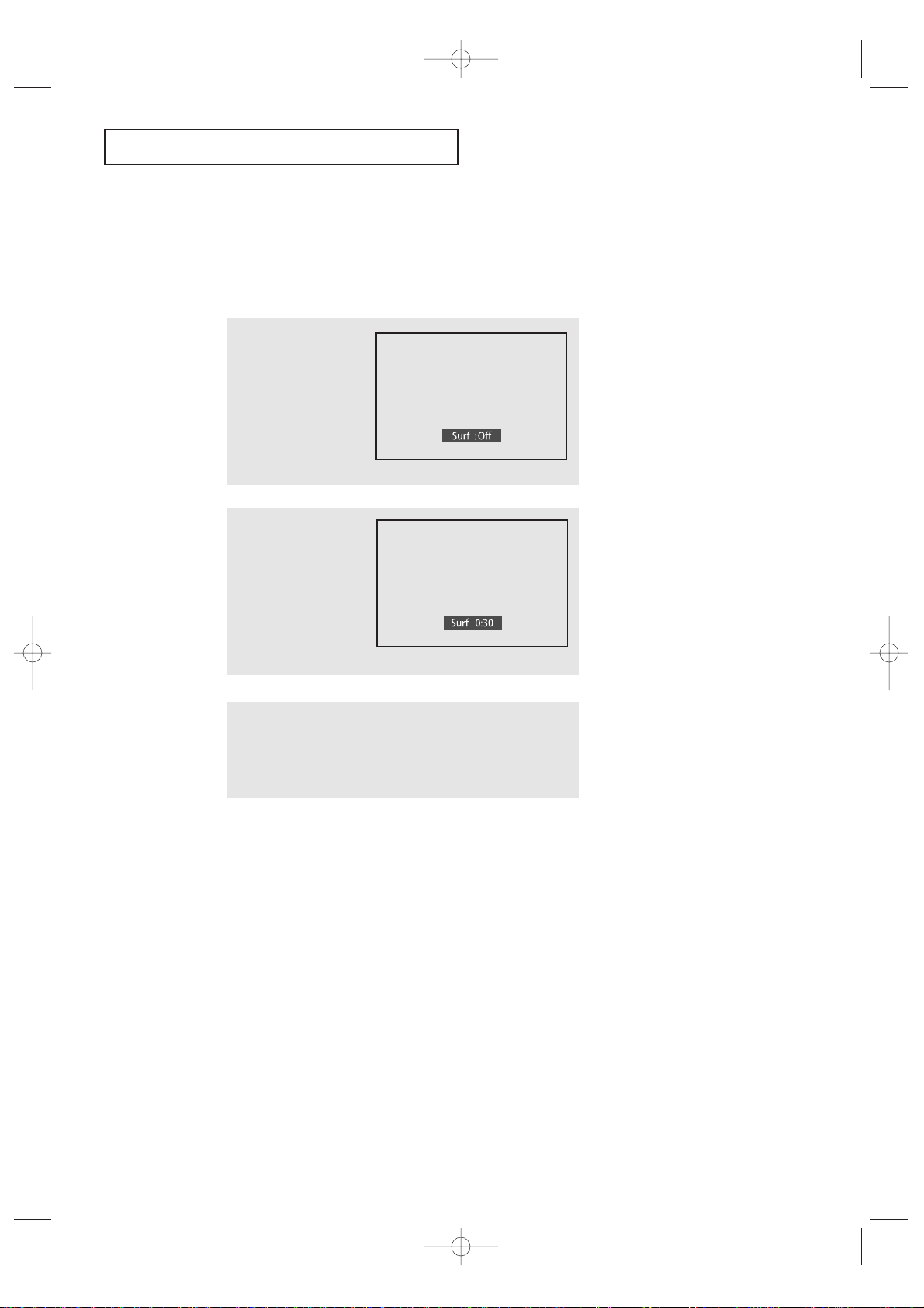
Using the R.Surf Feature
This feature allows you to set the TV to return to a particular channel after a certain
amount of time. For example, you may be watching a channel when commercials start.
You can set the R.Surf to “5 minutes”, then switch channels. After minutes, the TV will
return to the original channel. To use the R.Surf feature:
1
While you are watching
the channel to which you
want to return, press
R.SURF. The on-screen
display will read “Surf
off”.
2
Press R.SURF again to set
the timer in thirty second
intervals, up to five minutes.
3
The time you set will begin counting down on the screen.
When the time runs out, the TV will return to the channel
you were watching when you set the timer.
KS7A(ET)Latin_ENG 12/7/03 5:13 PM Page 49

SPECIAL FEATURES
50
Choosing a Multi-Channel Sound (MTS)
Soundtrack
Depending on the particular program being broadcast, you can listen to Stereo, Mono, or
a Separate Audio Program. (SAP audio is usually a foreign-language translation.
Sometimes SAP has unrelated information like news or weather.)
2
Press the ▼ button to
select the “MTS”, then
press the ENTER button.
3
Press the ▲ or ▼ button
to select “Mono”, “Stereo”
or “SAP”, then press the
ENTER button.
Press the EXIT button to
exit.
▼
The text at the bottom of the
menu tells you if the incoming
audio is Mono, Stereo or SAP.
1
Press MENU to display
the menu.
Press the ▼ button to
select the “Sound”, then
press the ENTER button.
• Choose Mono for channels that are broadcasting in mono, or if you are
having difficulty receiving a stereo signal.
• Choose Stereo for channels that are broadcasting in stereo.
• Choose SAP to listen to the Separate Audio Program, which is usually a
foreign-language translation.
▼
Quick way to access the MTS:
Just press the “MTS” button on the
remote control.
Move Enter Return
Sound
Mode : Custom
√√
Custom
√√
MTS : Mono
√√
Auto Volume : Off
√√
▼
More
Move Enter Return
Sound
Mode : Custom
√√
Custom
√√
MTS : Mono
Auto Volume : Off
√√
▼
More
Mono
Stereo
SAP
Move Enter Return
Sound
Mode : Custom
√√
Custom
√√
MTS : Mono
√√
Auto Volume : Off
√√
▼
More
KS7A(ET)Latin_ENG 12/7/03 5:13 PM Page 50
SPECIAL FEATURES
51
Extra sound settings (Auto Volume, Turbo
Sound or Pseudo Strero)
The following sound settings can be adjusted to suit your personal preferences
• Auto Volume
Each broadcasting station has its own signal conditions, which can make it necessary
to adjust the volume every time the channel is changed. “Auto volume” lets you
automat-ically adjust the volume of the desired channel by lowering the sound out
put when the modulation signal is high or by raising the sound output when the
modulation sig-nal is low.
•Turbo Sound
Turbo sound emphasizes the bass and treble frequencies to add fullness to the sound.
You can select the turbo sound by simply pressing the “TURBO” button on the remote
control.
• Pseudo Stereo
Pseudo Stereo converts a monaural sound signal into two identical left and right
channels. Once the Pseudo Stereo is set to “On” or “Off”, the setting applies to the
sound effects such as Standard, Music, Movie and Speech.
1
Press the MENU button to
display the menu.
Press the ▼ button to
select the “Sound”, then
press the ENTER button.
2
Press the ▲ or ▼ button
to select the required item
(Auto Volume, Turbo
Sound, Pseudo Stereo),
then press the ENTER
button.
3
Press the ▼ button to
select “On”, then press
the
ENTER button.
Press the EXIT button to
exit.
Move Enter Return
Sound
Mode : Custom
√√
Custom
√√
MTS : Mono
√√
Auto Volume : Off
▼
More
Off
On
Move Enter Return
Sound
▲
More
Turbo sound : Off
Pseudo stereo : Mono
√√
Off
On
Move Enter Return
Sound
▲
More
Turbo sound : Off
√√
Pseudo stereo : Off
Off
On
Move Enter Return
Sound
Mode : Custom
√√
Custom
√√
MTS : Mono
√√
Auto Volume : Off
√√
▼
More
KS7A(ET)Latin_ENG 12/7/03 4:59 PM Page 51

SPECIAL FEATURES
52
LNA (Low Noise Amplifier)
If the TV is operating in a weak-signal area, sometimes the LNA function can improve
the reception (a low-noise preamplifier boosts the incoming signal).
1
Press MENU to display
the menu.
Press the ▼ button to
select the “Channel”, then
press the ENTER button.
▼
Pressing ▲ or ▼ will alternate
between “On” and “Off”.
2
Press the ▼ button to
select “LNA”, then press
the ENTER button.
3
Press the ▲ or ▼ button
to select “On”, then press
the ENTER button.
Press the EXIT button to
exit.
Move Enter Return
Channel
Auto Program
√√
Add/Delete : Deleted
√√
Air/CATV : Air
Labeling :
----
LNA : Off
√√
Move Enter Return
Channel
Auto Program
√√
Add/Delete : Deleted
√√
Air/CATV : Air
Labeling :
----
LNA : Off
Off
On
Move Enter Return
Channel
Auto Program
√√
Add/Delete : Deleted
√√
Air/CATV : Air
Labeling :
----
LNA : Off
√√
KS7A(ET)Latin_ENG 12/7/03 4:59 PM Page 52

SPECIAL FEATURES
53
Setting the On/Off Timer
1
Press the MENU button to
display the menu.
Press the ▼ button to
select the “Setup”, then
press the ENTER button.
2
Press the ENTER button to
select "Time".
▼
Before using the timer, you must
set the TV’s clock. (See “Setting the
Clock” on page 33).
When any of the timers are set, the
“Timer” LED will illuminate (front
panel of TV.)
Move Enter Return
Setup
Time
√√
Plug & Play
√√
Captions
√√
Language : English
▼
More
3
Press the ▼ button to
select the “On Time”, then
press the ENTER button.
Press the ▲ or ▼ button
repeatedly to select the
appropriate hours (i.e.,
the hour when the TV
will turn on.)
Move Adjust Return
Time
Clock 09: 30am
On Time 06 : - - am Off
Off Time - - : - - am Off
Sleep Timer : Off
On Time Volume : 10
4
Press the √√button to
select the minutes.
(The minutes digits will
be highlighted.)
Press the
▲ or ▼ button
to select the appropriate
minutes.
Move Adjust Return
Time
Clock 09: 30am
On Time 06 : 30am Off
Off Time - - : - - am Off
Sleep Timer : Off
On Time Volume : 10
Move Enter Return
Setup
Time
√√
Plug & Play
√√
Captions
√√
Language : English
▼
More
KS7A(ET)Latin_ENG 12/7/03 4:59 PM Page 53
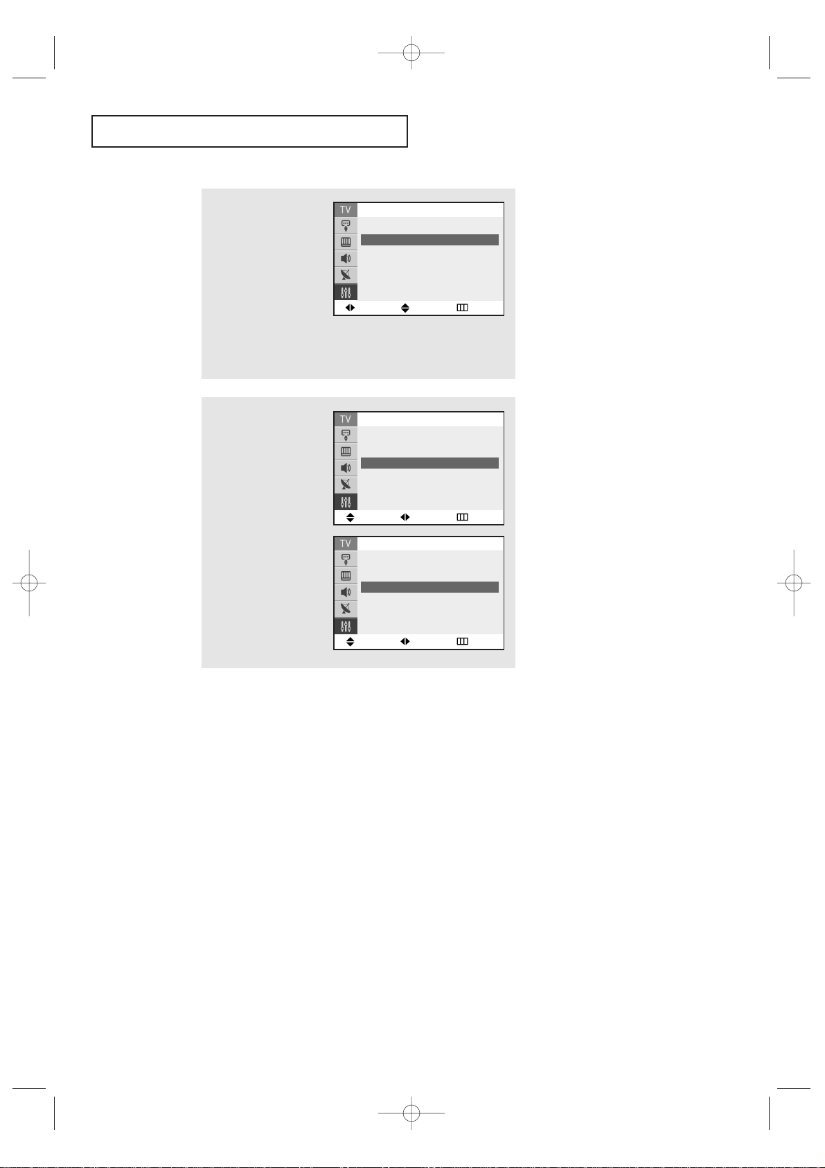
SPECIAL FEATURES
54
6
To set the Off time, press
the ▼ button to select
“Off Time”.
Press the √√button and
set the hours and minutes.
(Follow the same procedure as in steps 1~5
above.)
When finished setting
the timer, press the EXIT
button to exit.
▼
Absent Power Off
When you set the timer “On”, your
television will eventually be turned
off, if you do not operate any
controls during the 3 hours after the
TV is turned on by timer.
This function is available in only the
timer “On” mode and will prevent a
leakage accident or overheating,
caused by your TV left on for a long
time due to the timer “On” (when
you are away on holiday, for
example).
Move Adjust Return
Time
Clock 09: 30am
On Time 06 : 30am On
Off Time - - : - - am Off
Sleep Timer : Off
On Time Volume : 10
Move Adjust Return
Time
Clock 09: 30am
On Time 06 : 30am On
Off Time 12: 00pm On
Sleep Timer : Off
On Time Volume : 10
5
Press the √√button to
select “On” or “Off”.
Press the ▲ or ▼ button
to turn the on-timer “On”.
(Repeatedly pressing the
▲ or ▼ button will alternate between on and off.)
When finished, press the
MENU button.
▼
To deactivate the “On time,”
select “Off” during this step.
Move Adjust Return
Time
Clock 09: 30am
On Time 06 : 30am On
Off Time - - : - - am Off
Sleep Timer : Off
On Time Volume : 10
KS7A(ET)Latin_ENG 12/7/03 4:59 PM Page 54

SPECIAL FEATURES
55
1
Press the SLEEP button on
the remote control.
2
Press the SLEEP button
repeatedly until the appropriate time interval
appears (any of the preset
values from “Off” to
“180”).
▼
After about 5 seconds, the sleep
display will disappear from the
screen, and the time interval will be
set.
Setting the Sleep Timer
The sleep timer automatically shuts off the TV after a preset time
(from 10 to 180 minutes).
Sleep Timer Off
Sleep Timer 30
KS7A(ET)Latin_ENG 12/7/03 4:59 PM Page 55

SPECIAL FEATURES
56
Setting the Preferred Volume Level
The preferred volume can be set for when the timer automatically turns on the TV.
1
Press the MENU button to
display the menu.
Press the ▼ button to
select the “Setup”, then
press the ENTER button.
2
Press the ENTER button to
select "Time".
Move Enter Return
Setup
Time
√√
Plug & Play
√√
Captions
√√
Language : English
▼
More
3
Press the ▼ button to
select “On Time Volume”.
Press the
œœ
or √√button
to adjust volume level.
Move Adjust Return
Time
Clock 09: 30am
On Time 06 : 30am On
Off Time 12: 00pm On
Sleep Timer : Off
On Time Volume : 15
Move Adjust Return
Time
Clock 09: 30am
On Time 06 : 30am On
Off Time 12: 00pm On
Sleep Timer : Off
On Time Volume : 10
KS7A(ET)Latin_ENG 12/7/03 4:59 PM Page 56

SPECIAL FEATURES
57
▼
Misspellings and unusual
characters sometimes occur during
closed caption transmissions, especially
those of live events. There may be a
small delay before captions appear when
you change channels. These are not
malfunctions of the TV.
3
Press the ENTER button,
then press the ▲ or ▼
button to turn closed
captioning “On” or “Off”.
Press the ENTER button.
▼
In “Caption” mode, captions appear
at the bottom of the screen, and they usually cover only a small portion of the
picture.
In “Text” mode, information unrelated to
the program, such as news or weather, is
displayed. Text often covers a large
portion of the screen.
4
Press the ▼ button to
select “Mode”, then press
the
ENTER button.
Press the
▲ or ▼ button
to select “Captions” or
“Text”, then press the
ENTER button.
Viewing Closed Captions
Your TV decodes and displays the closed captions that are broadcast with certain TV shows.
These captions are usually subtitles for the hearing impaired or foreign-language translations.
All VCRs record the closed caption signal from television programs, so home-recorded video
tapes also provide closed captions. Most pre-recorded commercial video tapes provide closed
captions as well. Check for the closed caption symbol in your television schedule and on the
tape’s packaging: .
1
Press the MENU button to
display the menu.
Press the ▼ button to
select the “Setup”, then
press the ENTER button.
2
Press the ▼ button to
select the “Caption”, then
press the ENTER button.
▼
5
Depending on the particular broadcast, it might be necessary to
make changes to “Channels” and “Field”:
Use the ▲, ▼,
œœ
and
√√
buttons to make the changes. (Follow
the same procedure as in steps 3~4 above.)
Press the EXIT button to exit.
Different channels and fields
display different information: Field 2
carries additional information that
supplements the information in Field 1.
(For example, Channel 1 may have
subtitles in English, while Channel 2 has
subtitles in Spanish.)
Move Enter Return
Setup
Time
√√
Plug & Play
√√
Captions
√√
Language : English
▼
More
Move Enter Return
Captions
Captions : Off
Mode : Captions
Channels : 1
Field : 1
Off
On
Move Enter Return
Captions
Captions : Off
Mode : Captions
Channels : 1
Field : 1
Captions
Text
Move Enter Return
Setup
Time
√√
Plug & Play
√√
Captions
√√
Language : English
▼
More
KS7A(ET)Latin_ENG 12/7/03 4:59 PM Page 57

SPECIAL FEATURES
58
Viewing Picture-in-Picture
You can use the PIP feature to simultaneously to watch two video sources.
Note:The PIP feature does not work with DVD signals and S-Video mode.
When PIP is selected in the Zoom mode, the Mode is automatically converted
into the Normal mode.
Activating Picture-in-Picture
1
Press MENU to display
the menu.
Press the
▼ button to
select the “Picture”, then
press the ENTER button.
2
Press the ▼ button to
select “PIP”, then press
the ENTER button.
3
Press the ENTER button
agian.
Press the ▼ button to
select PIP “On”, then
press the ENTER button.
Press the EXIT button to
exit.
▼
If you turn TV off while watching
and turn it on again, the PIP window
will disappear.
▼
Quick way to access the PIP:
Just press the PIP button on the
remote control.
Move Enter Return
▲
More
Digital NR : Off
√√
Tilt :
0
PIP
√√
Picture
Move Enter Return
PIP
PIP : Off
Off
On
Move Enter Return
PIP
PIP : On
√√
Source : TV
√√
Swap
√√
Position :
√√
Channel : Air 3
Move Enter Return
Mode : Custom
√√
Custom
√√
Color tone : Normal
√√
Size : Normal
√√
▼
More
Picture
KS7A(ET)Latin_ENG 12/7/03 4:59 PM Page 58

SPECIAL FEATURES
59
Selecting a Signal Source (External A/V) for PIP
1
Press MENU to display
the menu.
Press the ▼ button to
select the “Picture”, then
press the ENTER button.
2
Press the ▼ button to
select “PIP”, then press
the ENTER button.
3
Press the ▼ to select the
“Source”, then press the
ENTER button.
Press the ▲ or ▼ button
to select “TV”, “AV1”,
“AV2” or “S-Video”,
then press the ENTER
button.
Press the EXIT button to
exit.
Move Enter Return
PIP
PIP : On
√√
Source : TV
√√
Swap
√√
Position :
√√
Channel : Air 3
Move Enter Return
PIP
PIP : On
√√
Source : TV
Swap
√√
Position :
√√
Channel : Air 3
TV
AV1
AV2
S-Video
▼
For more information about
external A/V components and signals,
see “Viewing an External Signal
Source” on page 40.
If you select “TV”, the PIP image is
the same as the main image.
Move Enter Return
▲
More
Digital NR : Off
√√
Tilt :
0
PIP
√√
Picture
Move Enter Return
Mode : Custom
√√
Custom
√√
Color tone : Normal
√√
Size : Normal
√√
▼
More
Picture
KS7A(ET)Latin_ENG 12/7/03 4:59 PM Page 59

SPECIAL FEATURES
60
Swapping the Contents of the PIP image and Main image
1
Press MENU to display
the menu.
Press the ▼ button to
select the “Picture”, then
press the ENTER button.
2
Press the ▼ button to
select “PIP”, then press
the ENTER button.
3
Press the ▼ to select the
“Swap”, then press the
ENTER button.
The image in the PIP
window will appear
on the main screen,
and vice versa.
Press the EXIT button
to exit.
▼
Quick way to access the SWAP:
Just press the SWAP button on the
remote control.
Move Enter Return
PIP
PIP : On
√√
Source : TV
√√
Swap
√√
Position :
√√
Channel : Air 3
Move Enter Return
Mode : Custom
√√
Custom
√√
Color tone : Normal
√√
Size : Normal
√√
▼
More
Picture
Move Enter Return
▲
More
Digital NR : Off
√√
Tilt :
0
PIP
√√
Picture
KS7A(ET)Latin_ENG 12/7/03 4:59 PM Page 60

SPECIAL FEATURES
61
Changing the Position of the PIP Window
1
Press MENU to display
the menu.
Press the ▼ button to
select the “Picture”, then
press the ENTER button.
2
Press the ▼ button to
select “PIP”, then press
the ENTER button.
3
Press the ▼ to select the
“Position”, then press the
ENTER button.
Press the ▲ or ▼ button
to select the required
screen positon,then
press the ENTER button.
Press the EXIT button to
exit.
Move Enter Return
PIP
PIP : On
√√
Source : TV
√√
Swap
√√
Position :
√√
Channel : Air 3
Move Enter Return
PIP
PIP : On
√√
Source : TV
√√
Swap
√√
Position :
Channel : Air 3
Move Enter Return
Mode : Custom
√√
Custom
√√
Color tone : Normal
√√
Size : Normal
√√
▼
More
Picture
Move Enter Return
▲
More
Digital NR : Off
√√
Tilt :
0
PIP
√√
Picture
KS7A(ET)Latin_ENG 12/7/03 5:00 PM Page 61

SPECIAL FEATURES
62
Changing the PIP Channel
1
Press MENU to display
the menu.
Press the ▼ button to
select the “Picture”, then
press the ENTER button.
2
Press the ▼ button to
select “PIP”, then press
the ENTER button.
3
Press the ▼ to select the
“Channel”.
Press the
œœ
or √√button
to change the channel
that appears in the PIP
window.
Press the EXIT button to
exit.
▼
Quick way to access the PIP channel:
Just press the CH or CH button on
the remote control.
Move Adjust Return
PIP
PIP : On
√√
Source : TV
√√
Swap
√√
Position :
√√
Channel : Air 3
Move Adjust Return
PIP
PIP : On
√√
Source : TV
√√
Swap
√√
Position :
√√
Channel : Air 5
Move Enter Return
Mode : Custom
√√
Custom
√√
Color tone : Normal
√√
Size : Normal
√√
▼
More
Picture
Move Enter Return
▲
More
Digital NR : Off
√√
Tilt :
0
PIP
√√
Picture
KS7A(ET)Latin_ENG 12/7/03 5:00 PM Page 62

SPECIAL FEATURES
63
Changing the Size of the PIP Window
1
Press the SIZE button
under the cover of the
remote control.
Press the SIZE button
repeatedly to cycle
through this sequence:
large window, small
window.
<Large Window>
<Small Window>
KS7A(ET)Latin_ENG 12/7/03 5:00 PM Page 63
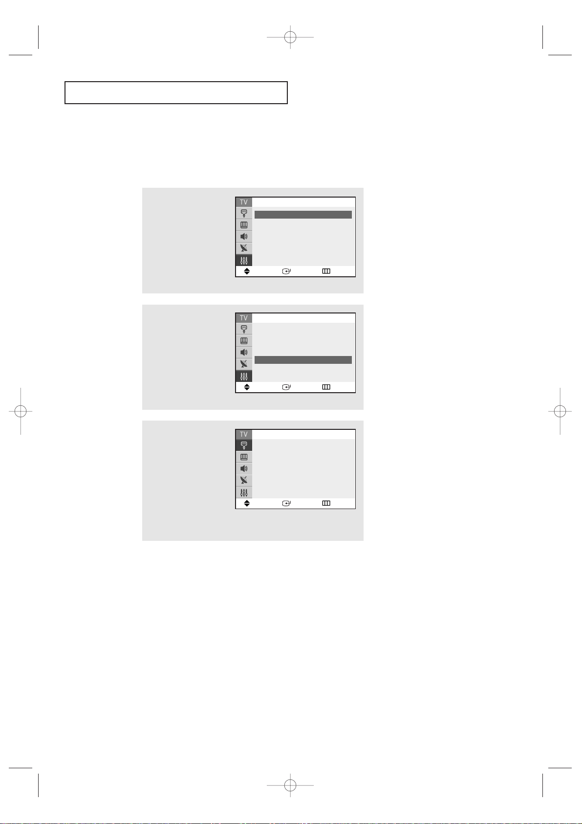
SPECIAL FEATURES
64
3
Each of the menu options
is displayed in turn.
When you wish to stop
the demonstration, press
any button on the remote
control.
Press the EXIT button to
exit.
Viewing the Demonstration
To become familiar with the various menus provided by your television, you can view
the in built demonstration.
1
Press MENU to display
the menu.
Press the ▼ button to
select the “Setup”, then
press the ENTER button.
2
Press the ▼ button to
select “Demonstration”,
then press the ENTER
button.
Move Enter Return
Setup
▲
More
Blue Screen : On
√√
Melody : On
√√
Demonstration
√√
Move Enter Exit
Source List : AV1
√√
Edit Name
√√
Input
Move Enter Return
Setup
Time
√√
Plug & Play
√√
Captions
√√
Language : English
▼
More
KS7A(ET)Latin_ENG 12/7/03 5:00 PM Page 64

MEMO
65
If the TV seems to have a problem, first try this list of possible problems and solutions.
If none of these troubleshooting tips apply, then call your nearest service center.
Identifying Problems
Problem Possible Solution
Poor picture Try another channel.
Adjust the antenna.
Check all wire connections.
Poor sound quality. Try another channel.
Adjust the antenna.
No picture or sound. Try another channel.
Press the TV/VIDEO button.
Make sure the TV is plugged in.
Check the antenna connections.
No color, wrong colors or tints. Make sure the program is broadcast in color.
Adjust the picture settings.
If the set is moved or turned in a different
direction, the power should be OFF for at least
30 minutes.
Picture rolls vertically. Adjust the antenna.
Check all wire connections.
The TV operates erratically Unplug the TV for 30 seconds, then try
operating it again.
The TV won’t turn on. Make sure the wall outlet is working.
SPECIAL FEATURES
Chapter Five
TROUBLESHOOTING
KS7A(ET)Latin_ENG 12/7/03 5:00 PM Page 65
MEMO
66
APPENDIX
Cleaning and Maintaining Your TV
With proper care, your TV unit will give you many years of service. Please follow these
guidelines to get the maximum performance from your TV.
Placement
• Do not place the TV near extremely hot, cold, humid or dusty places.
• Do not place the TV near appliances with electric motors that create magnetic fields,
such as vacuum cleaners.
• Keep the ventilation openings clear; do not place the TV on a soft surface, such as
cloth or paper.
• Place the TV in a vertical position only.
Liquids
• Do not handle liquids near or on the TV. Liquids that spill into it can cause serious
damage.
Cabinet
• Never open the cabinet or touch the parts inside.
•Wipe your TV with a clean, dry cloth. Never use water, cleaning fluids, wax, or
chemicals.
•Do not put heavy objects on top of the cabinet.
Temperature
• If your TV is suddenly moved from a cold to a warm place, unplug the power cord,
and allow at least two hours for moisture that may have formed inside the unit to dry
completely.
Using Your TV in Another Country
If you plan to take your TV with you to a foreign country, please be aware of the different
television systems that are in use around the world. A TV designed for one system may
not work properly with another system due to differences in the TV channel frequencies
Specifications
Model
Voltage
Frequency of Operation
Power Consumption
Dimensions
(mm/inches)
Weight (Kg/ lbs)
CL29A10
AC 100-240 V
50/60Hz
100 W
766 X 561 X 581/45.7
/ 30.15 X 22.08 X 22.87
45.7 / 100.75
CL34A10
AC 100-240 V
50/60Hz
100 W
910 X 585 X690/68.0
/ 35.82 X 23.03 X 27.16
68.0 / 149.91
CL29M6
AC 100-240 V
50/60Hz
100 W
730 X485 X575 /
28.74 X 19.09 X 22.63
44.9 / 98.98
KS7A(ET)Latin_ENG 12/7/03 5:00 PM Page 66

MEMO
67
KS7A(ET)Latin_ENG 12/7/03 5:00 PM Page 67
 Loading...