

PCB Diagram
Samsung Electronics 9-1
9. PCB Diagram
9-1 Main Board
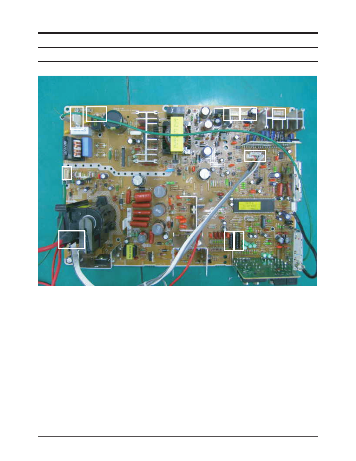
9-1-1 Assy Main Board
9-1-2 Names & Roles of Key Parts
* PD801S : This is a 3P connected to Power-cord.
* FN01 : This is a 4P connected to Tilt-Coil.
* CN502 : This is a 6P connected to Video amp B+,Heater Voltage in CRT PCB.
* CN702A : This is a 7P connected to S-VHS signal in Side AV PCB.
* CN701: This is a 8P connected to AV2 signal in Side AV PCB.
* CN503A : This is a 8P connected from MAIN PCB to CRT PCB for R,G,B,AKB signal.
* CNV901A : This is a 6P connected from Tact,S/W pcb for IR,LED,5V.
* CN902 : This is a 4P connected from Control PCB for Key1,Key2 input signal.
* CN601 : This is a 4P connected to Speaker for Sound output signal.
FN01
PD801S LC801S
CN502
CN702A
CNV901A
CN902
CN503A
CN701
CN601
PCB Diagram
9-2 Samsung Electronics
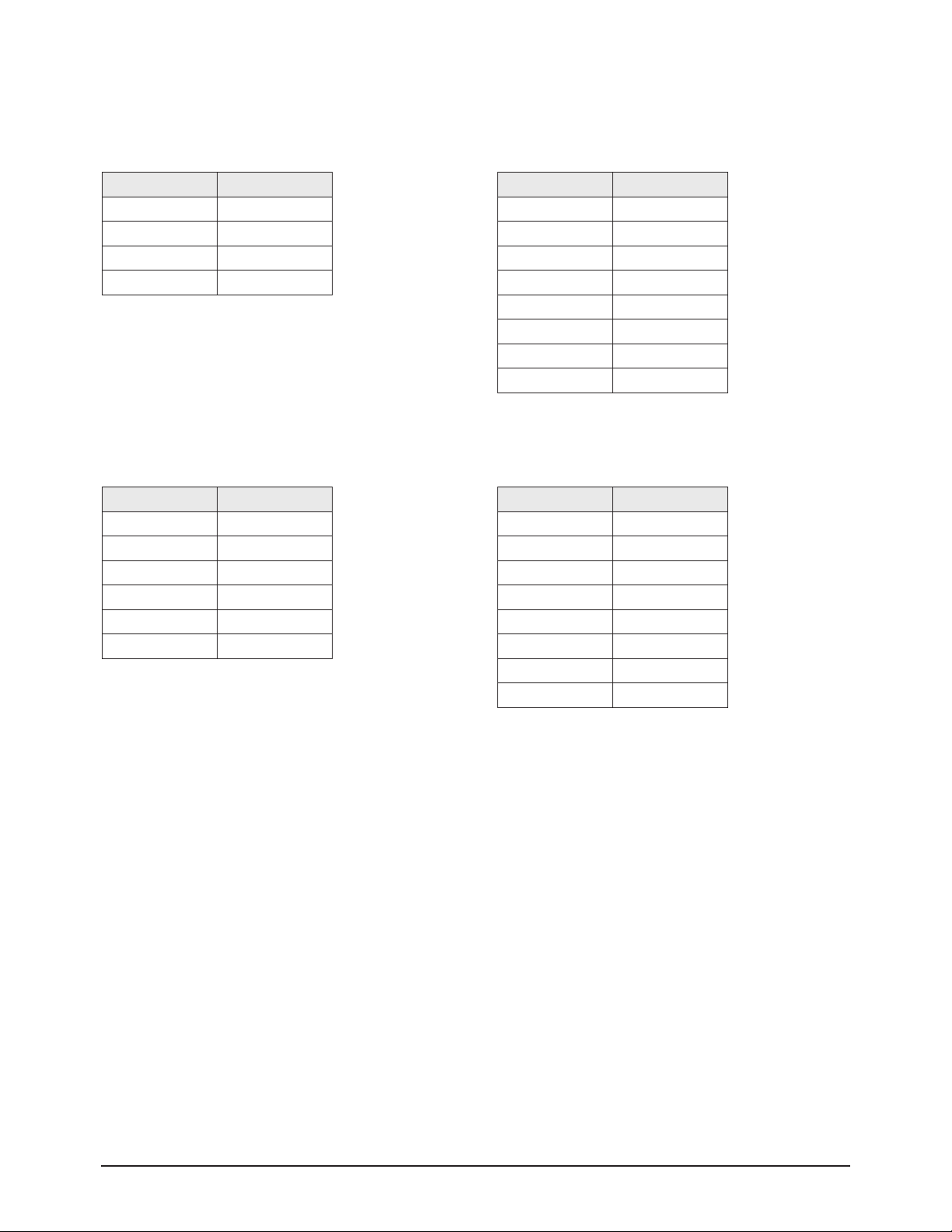
9-1-3 Main Board Connector Pin
CN601
Connected to the Side Sound Port
PIN No. Pin Name
1 R -
2 R+
3 L+
4 L-
PIN No. Pin Name
1 B
2 G
3 R
4 GND
5 SE
6 GND
7 F/B
8 TILT
CN503A
Connected to the CRT Ass'y
CN503B
Connecte to the CRT Ass'y
PIN No. Pin Name
1 -16.5V
2 +16.5V
3 GND
4 HEATER
5 NC
6 200V
PIN No. Pin Name
1 VO
2 GND
3 VI
4 GND
5 LO
6 RO
7 LI
8 RI
CN701
Connected to the Side AV Port
 Loading...