

SAMSUNG CL29Z30PQTXXAX Service Manual

COLOR TELEVISION RECEIVER
Chassis : KS7D(N)_Timecop
Model : CL29Z30PQTXXAX
COLOR TELEVISION RECEIVER FEATURES
■■
GREEN CRT
■
Turbo Voice
SERVICE
Manual
CL-29Z30PQ

This Service Manual is a property of Samsung Electronics Co.,Ltd.
Any unauthorized use of Manual can be punished under applicable
International and/or domestic law.
© Samsung Electronics Co., Ltd. Apr. 2006
Printed in Korea
AA82-03373A

Table of Contents
Chapter 1 Precaution
■ 1-1 Safety Precautions . . . . . . . . . . . . . . . . . . . . . . . . . . . . . . . . . . . . . . . . . . . . . . . . . . . . . . . . . . . 1-1
■ 1-2 Servicing Precautions . . . . . . . . . . . . . . . . . . . . . . . . . . . . . . . . . . . . . . . . . . . . . . . . . . . . . . . . 1-3
■ 1-3 Static Electricity Precautions . . . . . . . . . . . . . . . . . . . . . . . . . . . . . . . . . . . . . . . . . . . . . . . . . . . 1-4
■ 1-4 Installation Precautions . . . . . . . . . . . . . . . . . . . . . . . . . . . . . . . . . . . . . . . . . . . . . . . . . . . . . . . 1-5
Chapter 2 Product Specification
■ 2-1 Product Features . . . . . . . . . . . . . . . . . . . . . . . . . . . . . . . . . . . . . . . . . . . . . . . . . . . . . . . . . . . . 2-1
■ 2-2 Key Features . . . . . . . . . . . . . . . . . . . . . . . . . . . . . . . . . . . . . . . . . . . . . . . . . . . . . . . . . . . . . . . 2-2
■ 2-3 Specifications Analysis . . . . . . . . . . . . . . . . . . . . . . . . . . . . . . . . . . . . . . . . . . . . . . . . . . . . . . . . 2-3
■ 2-4 Accessories . . . . . . . . . . . . . . . . . . . . . . . . . . . . . . . . . . . . . . . . . . . . . . . . . . . . . . . . . . . . . . . . 2-4
Chapter 3 Alignment & Adjustment
■ 3-1 Service Instruction . . . . . . . . . . . . . . . . . . . . . . . . . . . . . . . . . . . . . . . . . . . . . . . . . . . . . . . . . . . 3-1
■ 3-2 How to Access Service Mode . . . . . . . . . . . . . . . . . . . . . . . . . . . . . . . . . . . . . . . . . . . . . . . . . . . 3-2
■ 3-3 Factory Data . . . . . . . . . . . . . . . . . . . . . . . . . . . . . . . . . . . . . . . . . . . . . . . . . . . . . . . . . . . . . . . . 3-3
■ 3-4 Service Adjustment . . . . . . . . . . . . . . . . . . . . . . . . . . . . . . . . . . . . . . . . . . . . . . . . . . . . . . . . . . 3-15
■ 3-5 Replacements & Calibration . . . . . . . . . . . . . . . . . . . . . . . . . . . . . . . . . . . . . . . . . . . . . . . . . . . . 3-17
Chapter 4 Exploded View & Part List
■ 4-1 CL29Z30PQTXXAX . . . . . . . . . . . . . . . . . . . . . . . . . . . . . . . . . . . . . . . . . . . . . . . . . . . . . . . . . . 4-1
Chapter 5 Electrical Part List
■ 5-1 CL29Z30PQTXXAX . . . . . . . . . . . . . . . . . . . . . . . . . . . . . . . . . . . . . . . . . . . . . . . . . . . . . . . . . . 5-1
Chapter 6 Troubleshooting
■ 6-1 Checkpoints by Error Mode . . . . . . . . . . . . . . . . . . . . . . . . . . . . . . . . . . . . . . . . . . . . . . . . . . . . 6-1
■ 6-2 Troubleshooting Procedures by Error Modes . . . . . . . . . . . . . . . . . . . . . . . . . . . . . . . . . . . . . . . 6-3
■ 6-3 Troubleshooting Procedures by ASS'Y . . . . . . . . . . . . . . . . . . . . . . . . . . . . . . . . . . . . . . . . . . . 6-4
■ 6-4 Troubleshooting by Blocks . . . . . . . . . . . . . . . . . . . . . . . . . . . . . . . . . . . . . . . . . . . . . . . . . . . . . 6-6
Chapter 7 Block Diagram
■ 7-1 Overall Block Diagram . . . . . . . . . . . . . . . . . . . . . . . . . . . . . . . . . . . . . . . . . . . . . . . . . . . . . . . . 7-1
■ 7-2 Partial Block Diagram . . . . . . . . . . . . . . . . . . . . . . . . . . . . . . . . . . . . . . . . . . . . . . . . . . . . . . . . . 7-2
Chapter 8 Wiring Diagram
■ 8-1 Overall Wiring . . . . . . . . . . . . . . . . . . . . . . . . . . . . . . . . . . . . . . . . . . . . . . . . . . . . . . . . . . . . . . . 8-1
■ 8-2 Pin Connection . . . . . . . . . . . . . . . . . . . . . . . . . . . . . . . . . . . . . . . . . . . . . . . . . . . . . . . . . . . . . . 8-2

Chapter 9 PCB Diagram
■ 9-1 Main Board . . . . . . . . . . . . . . . . . . . . . . . . . . . . . . . . . . . . . . . . . . . . . . . . . . . . . . . . . . . . . . . . . 9-1
■ 9-2 CRT Board . . . . . . . . . . . . . . . . . . . . . . . . . . . . . . . . . . . . . . . . . . . . . . . . . . . . . . . . . . . . . . . . . 9-3
Chapter 10 Schematic Diagram
■ 10-1 MAIN . . . . . . . . . . . . . . . . . . . . . . . . . . . . . . . . . . . . . . . . . . . . . . . . . . . . . . . . . . . . . . . . . . . . 10-1
■ 10-2 POWER . . . . . . . . . . . . . . . . . . . . . . . . . . . . . . . . . . . . . . . . . . . . . . . . . . . . . . . . . . . . . . . . . . 10-2
■ 10-3 Sound . . . . . . . . . . . . . . . . . . . . . . . . . . . . . . . . . . . . . . . . . . . . . . . . . . . . . . . . . . . . . . . . . . . . 10-3
Chapter 11 Operation Instruction & Installation
■ 11-1 Product Features and Functions . . . . . . . . . . . . . . . . . . . . . . . . . . . . . . . . . . . . . . . . . . . . . . . 11-1
Chapter 12 Disassembly & Reassembly
■ 12-1 Overall Disassembly & Reassembly . . . . . . . . . . . . . . . . . . . . . . . . . . . . . . . . . . . . . . . . . . . . 12-1
Chapter 13 Circuit Description
■ 13-1 Overall Block Description . . . . . . . . . . . . . . . . . . . . . . . . . . . . . . . . . . . . . . . . . . . . . . . . . . . . . 13-1
■ 13-2 Partial Block Description . . . . . . . . . . . . . . . . . . . . . . . . . . . . . . . . . . . . . . . . . . . . . . . . . . . . . 13-2
Chapter 14 Reference Information
■ 14-1 Option Byte . . . . . . . . . . . . . . . . . . . . . . . . . . . . . . . . . . . . . . . . . . . . . . . . . . . . . . . . . . . . . . . 14-1
■ 14-2 Technical Terms . . . . . . . . . . . . . . . . . . . . . . . . . . . . . . . . . . . . . . . . . . . . . . . . . . . . . . . . . . . . 14-2
Product Specification
Samsung Electronics 2-1
2. Product Specification
2-1 Product Features
Block Specfication Core Parts Remark
CRT - 29" Slim-fit
RF Part - Analog Tuners
NTSC Tuner(Argemtma option)
Power
- Input Voltage: AC100-240V(Mexico : AC127V)
-Stand-By: Less than 2.6W
STR-X6750F
Video
-1H Comb Filter
-Digital Nr
-BLE
VCT4822_F1
Audio
- OutPut: 10W+10W
- Fuction: Melody on/off, Turbo Voice, Auto Volume, Pseudo Stereo
VCT4822_F1
TDA7297SA (10W+10W)
Cabinet Front and Back Cabinets Z30 Design Applied Material: HIPS
Other
- Development Level : Level 4
- ProtoType Model:CL29Z30PQTXXAX
- Receving(P/G) CH: VHF:2 ~ 13, UHF:14 ~ 69, CATV:1 - 125
■ Core Parts Functions
- VCT4822_F1: Sound Processor, Video Processor, Display and Deflection Processor Controller, OSD and Text Processing
- TDA7297SA : Sound Signal Amplify
- STR-X6750F: Power Supply HIC
- TDQ-6F/13F2S (Tuner): RF signal processing , output IF signal
- TECCIO4OSL32A(E) : 2Tuner-PIP Main tuner
- TMQH2-003A,2 Tuner-PIP Sub tuner
Product Specification
2-2 Samsung Electronics
2-2 Key Features
Model CL-29Z30PQ
Voltage AC100-240 V(Mexico : AC127V)
Frequency of Operation 50/60 Hz
Power Consumption 140 Watts
Dimensions (mm/inches)
36.7 x 15.9 x 22.3 inches
796 x 415 x 586 mm
Weight (Kg/ lbs) 42.0 Kg / 92.6 Ibs
■ H/W Configuration
- 29" Slim fit CRT adopted
■ Picture
- System NTSC-M & Pal-M/N
- OSD: Half tone Menu
- DVD-input (Y,Pb,Pr) & S-VHS Option,
- AKB(Auto kinetic Bias)
- Comb Filter: 1H Comb filter
- Auto Peaking Control, Fine Tuneless, Group Delay Correction
■ Sound
- System: Stereo, Nicam
- Output:10W+10W
- AVL, Melody, Auto Stereo, Auto Mute, Equalizer
■ Feature
- Auto program, Sleep timer, Clock
- Caption
- Zoom, Previous channel, Blue Screen, Color Tone
■ In/Out Terminals
- Front: AV IN, S-VHS Input (Rear)
- Rear: 2 AV Input & Component video share
1 Component Input : 480i, RF 1 Input
1 AV Output
■ Remocon
- TM85
■ Power Supply
- 100V ~ 240V, (Mexico : 120V)
■ Power Comsumption
- Standy-by: Less than 2.6W
- Standard Power: 140W
Product Specification
Samsung Electronics 2-3
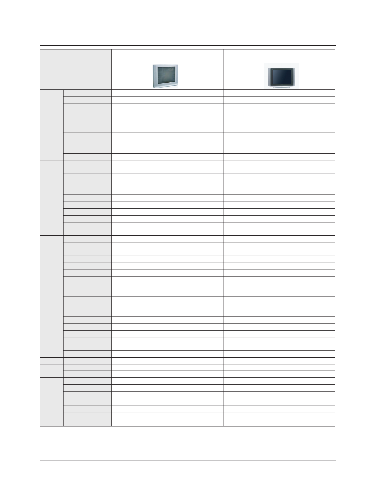
2-3 Specifications Analysis
Model CL29M6PQ CL-29Z30PQ
Chassis KS7A KS7D
Design
Picture
Screen Size 29" 29"
CRT FLAT SLIM-FIT
DNIe Jr.
■
X
Comb Filter 1H 1H
Velocity Modulation O X
Video Noise Reduction O O
Auto Kinetic Bias O O
Color Tone Control O O
Tilt Control O O
Picture Mode 4 Mode 4 Mode
Sound
MTS/SAP O O
Output Power(RMS) 15W*2 10W*2
Tweeter X X
BBE X X
Surround O O
Sound Mode 5 Mode 5 Mode
Graphic Equalizer O X
Sub-Woofer Speaker X X
Auto Volume Leveler O O
Melody On/Off O O
Turbo Sound O O
Convenience
PIP 2T 2T
Plug & Play O O
Zoom Mode O O
OSD Demo O O
OSD Language E/F/S/P E/F/S/P
Previous Channel O O
Closed Caption O O
On/Off Timer O O
Sleep Timer O O
Auto Power Off O O
Clock O O
Channel Scan X X
Self-diagnostic System X X
Remote Control TM76 TM85
Remote Surf O O
Channel Labelling O O
Blue Screen O O
Rack X X
Voltage Voltage 100~240 AC120V
Power
Consumption
On 145W 140W
Stand-by under 3W under 3W
Jacks
RF Input R1 R1
A/V Input S1/R2 S1/R2
Monitor Output R1 R1
S-VHS Input S1/R1 S1
Headphone X X
DVD Input O O
PC Input(VGA) X X
Product Specification
2-4 Samsung Electronics
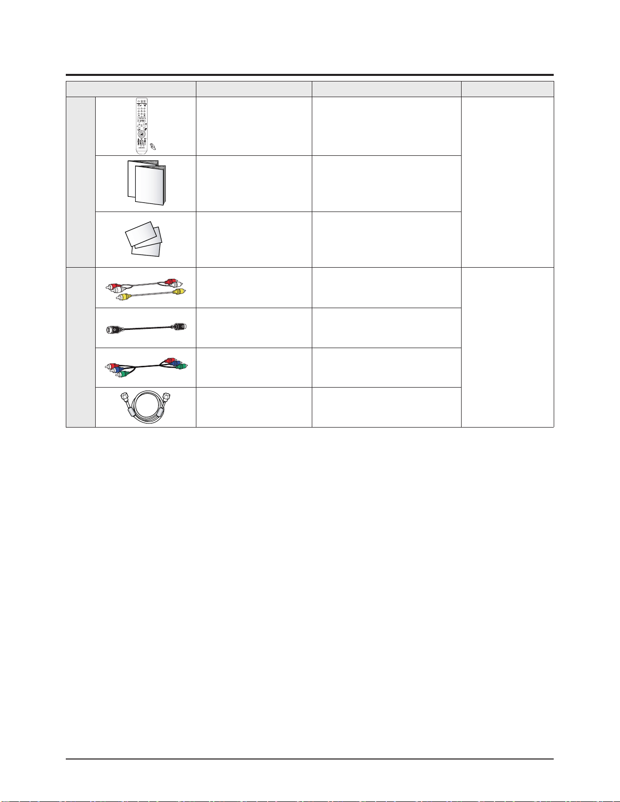
2-4 Accessories
Accessories Item Item code Remark
Supplied Accessories
Remote Control
AAA Alkaline Battery (2)
AA59-00384A
4301-000103
Samsung Service
center
Owner's Instructions
Safety Guide Manual
AA68-03806A
AA68-03242F
Warranty Card
Registration Card
BN68-00797A
BP68-00515A
Accessories that can be purchased
additionally
Video Cable /
Audio Cable
-
Internal shopping mall
S-Video Cable -
Component Cable -
Antenna Cable -
1. Make sure all protective devices are properly installed
including non-metallic handles and compartment covers
when installing or re-installing the chassis or chassis
assemblies.
2. Make sure that no gaps exist between the cabinets for
children to insert their fingers in to prevent children from
receiving electric shocks. Gaps mentioned above include
ventilation holes of a too great magnitude between the
vaccum tube and the cabinet mask, and the improper
installation of the rear cabinet.
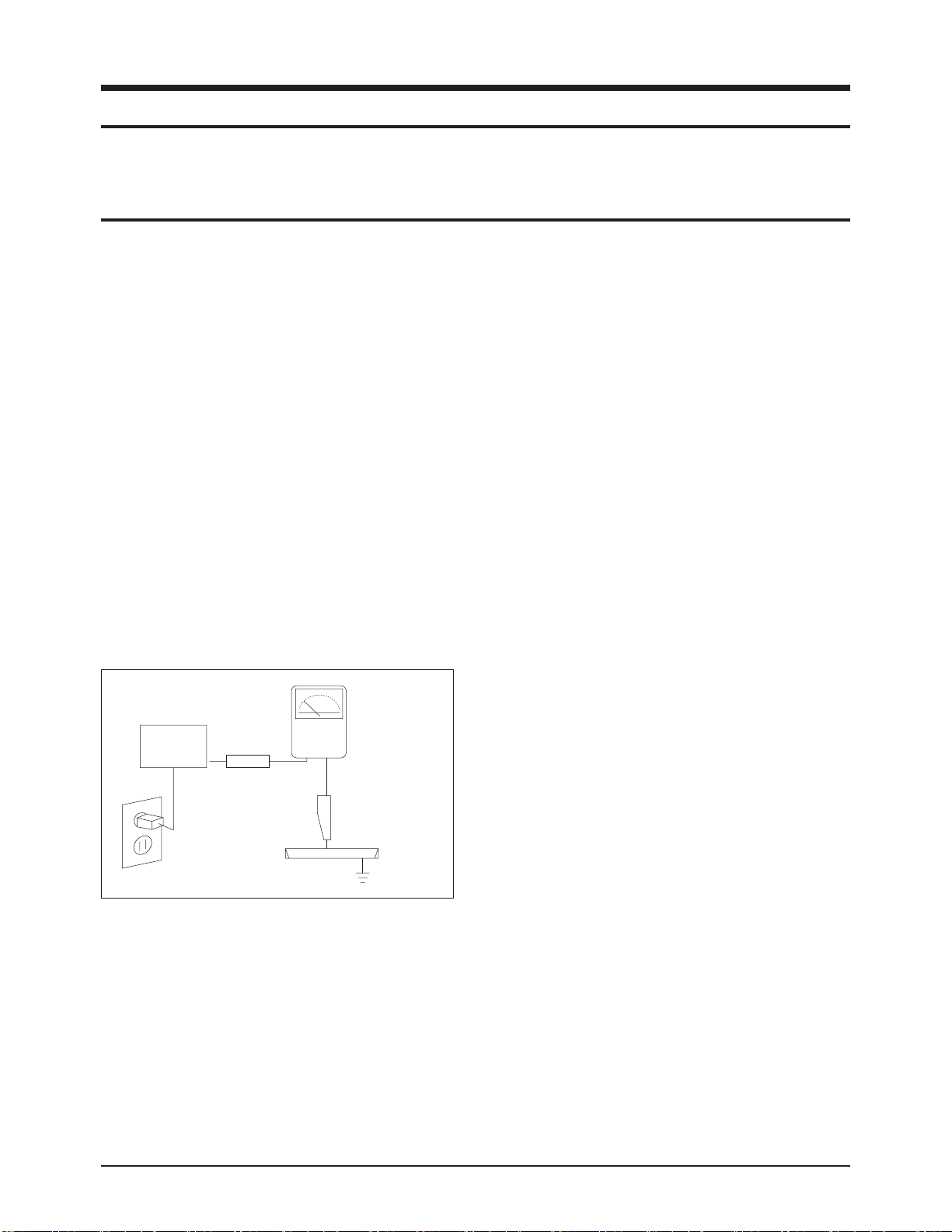
Errors may occur when the resistance is below 1.0 ㏁ or
over 5.2 ㏁.
In these cases, make sure that the device is repaired
before sending it back to the customer.
3. Check for Electricity Leakage (Figure 1-1)
Warning: Do not use an insulated transformer for checking the leakage. Use only those current leakage testers
or mirroring systems that comply with ANSIC 101.1 and
the Underwriter Laboratory's specifications (UL1410,
59.7).
Fig. 1-1 AC Leakage Test
4. A high voltage is maintained within the specified limits
using safety parts, calibration and tolerances. When
voltage exceeds the specified limits, check each special
part.
5. Warning for Engineering Changes:
Never make any changes or additions to the circuit
design or the internal part for this product.
Ex: Do not add any audio or video accessory
connectors. This might cause physical damage.
Furthermore, any changes or additions to the original
design/engineering will invalidate the warranty.
6. Warning - Hot Chassis:
Some TV chassis are directly connected to one end of
the AC power cord for electrical reasons.
Without insulated transformers, the product can only be
repaired safely when the chassis is connected to the
earthed end of the AC power source.
To make sure the AC power cord is properly connected,
follow the instructions below. Use the voltmeter to
measure the voltage between the chassis and the
earthed ground. If the measurement is over 1.0V, unplug
the AC power cord and change the polarity before reinserting it. Measure the voltage between the chassis
and the ground again.
7. Some TV chassis are shipped with an additional
secondary grounding system. The secondary system is
adjacent to the AC power line. These two grounding
systems are separated in the circuit using an
unbreakable/unchangeable insulation material.
8. When any parts, material or wiring appear overheated or
damaged, replace them with new regular ones
immediately. When any damage or overheating is
detected, correct this immediately and make a regular
check of possible errors.
9. Check for the original shape of the lead, especially that
of the antenna wiring, any sharp edges, the AC power
and the high voltage power. Carefully check if the wiring
is too tight, incorrectly placed or loose. Never change the
space between the part and the printed circuit board.
Check the AC power cord for possible damages. Keep
the part or the lead away from any heat-emitting
materials.
Precaution
Samsung Electronics 1-1
To avoid possible damages or electric shocks or exposure to radiation, follow the instructions below with regard to safety,
installation, service and ESD.
1. Precaution
1-1 Safety Precautions
(READING SHOULD
DEVICE
UNDER
TEST
2-WIRE CORD
ALSO TEST WITH
PLUG REVERSED
(USING AC ADAPTER
PLUG AS REQUIRED)
TEST ALL
EXPOSED METAL
SURFACES
LEAKAGE
CURRENT
TESTER
NOT BE ABOVE
0.5mA)
EARTH
GROUND

10. Safety Indication:
Some electrical circuits or device related materials
require special attention to their safety features, which
cannot be viewed by the naked eye. If an original part is
replaced with another irregular one, the safety or
protective features will be lost even if the new one has a
higher voltage or more watts.
Critical safety parts should be bracketed with ( ).
Use only regular parts for replacements (in particular,
flame resistance and dielectric strength specifications).
Irregular parts or materials may cause electric shock or
fire.
Precaution
1-2 Samsung Electronics
!

1. The service instructions are printed on the cabinet, and
should be followed by any service personnel.
2. Make sure to unplug the AC power cord from the power
source before starting any repairs.
(a) Remove or re-install parts or assemblies.
(b) Disconnect the electric plug or connector, if any.
(c) Connect the test part in parallel with the electrolytic
capacitor.
3. Some parts are placed at a higher position than the
printed board. Insulated tubes or tapes are used for this
purpose. The internal wiring is clamped using buckles to
avoid contact with heat emitting parts. These parts are
installed back to their original position.
4. After the repair, make sure to check if the screws, parts
or cables are properly installed. Make sure no damage is
caused to the repaired part and its surroundings.
5. Check for insulation between the blade of the AC plug
and that of any conductive materials (i.e. the metal
panel, input terminal, earphone jack, etc).
6. Insulation Check Process: Unplug the power cord from
the AC source and turn the switch on. Connect the insulating resistance meter (500v) to the AC plug blade.
The insulating resistance between the blade of the AC
plug and that of the conductive material should be more
than 1 ㏁.
7. Any B+ interlock should not be damaged.
If the metal heat sink is not properly installed, no
connection to the AC power should be made.
8. Make sure the grounding lead of the tester is connected
to the chassis ground before connecting to the positive
lead. The ground lead of the tester should be removed
last.
9. Beware of risks of any current leakage coming into
contact with the high-capacity capacitor.
10. The sharp edges of the metal material may cause
physical damage, so ensure wearing protective gloves
during the repair.
Precaution
Samsung Electronics 1-3
Warning 1: First carefully read the "Safety Instruction" in this service manual.
When there is a conflict between the service and the safety instructions, follow the safety instruction at all times.
Warning 2: Any electrolytic capacitor with the wrong polarity will explode.
1-2 Servicing Precautions

1-3 Static Electricity Precautions
1. Some semi-conductive ("solid state") devices are
vulnerable to static electricity. These devices are known
as ESD. ESD includes the integrated circuit and the field
effect transistor. To avoid any materials damage from
electrostatic shock, follow the instructions described
below.
2. Remove any static electricity from your body by
connecting the earth ground before handling any
semi-conductive parts or ass'ys. Alternatively, wear a
dischargeable wrist-belt.
(Make sure to remove any static electricity before
connecting the power source - this is a safety instruction
for avoiding electric shock)
3. Remove the ESD ass'y and place it on a conductive
surface such as aluminum foil to prevent accumulating
static electricity.
4. Do not use any Freon-based chemicals.
Such chemicals will generate static electricity that
causes damage to the ESD.
5. Use only grounded-tip irons for soldering purposes.
6. Use only anti-static solder removal devices.
Most solder removal devices do not support an
anti-static feature. A solder removal device without an
anti-static feature can store enough static electricity to
cause damage to the ESD.
7. Do not remove the ESD from the protective box until the
replacement is ready. Most ESD replacements are
covered with lead, which will cause a short to the entire
unit due to the conductive foam, aluminum foil or other
conductive materials.
8. Remove the protective material from the ESD
replacement lead immediately after connecting it to the
chassis or circuit ass'y.
9. Take extreme caution in handling any uncovered ESD
replacements. Actions such as brushing clothes or lifting
your leg from the carpet floor can generate enough static
electricity to damage the ESD.
Precaution
1-4 Samsung Electronics
CAUTION
These servicing instructions are for use by
qualified service personnel only.
To reduce the risk of electric shock do not
perform any servicing other than that contained in the
operating instructions unless you are qualified to do so.

Precaution
Samsung Electronics 1-5
1-4 Installation Precautions
1. For safety reasons, more than two people are required
for carrying the product.
2. Keep the power cord away from any heat emitting
devices, as a melted covering may cause fire or electric
shock.
3. Do not place the product in areas with poor ventilation
such as a bookshelf or closet. The increased internal
temperature may cause fire.
4. Bend the external antenna cable when connecting it to
the product. This is a measure to protect it from being
exposed to moisture. Otherwise, it may cause a fire or
electric shock.
5. Make sure to turn the power off and unplug the power
cord from the outlet before repositioning the product.
Also check the antenna cable or the external connectors
if they are fully unplugged. Damage to the cord may
cause fire or electric shock.
6. Keep the antenna far away from any high-voltage cables
and install it firmly. Contact with the high-voltage cable or
the antenna falling over may cause fire or electric shock.
7. Check the basics of the screen test.
- Image position/size, Tilt adjustment

1-6 Samsung Electronics
MEMO
Reference Information
Samsung Electronics 14-1
14. Reference Information
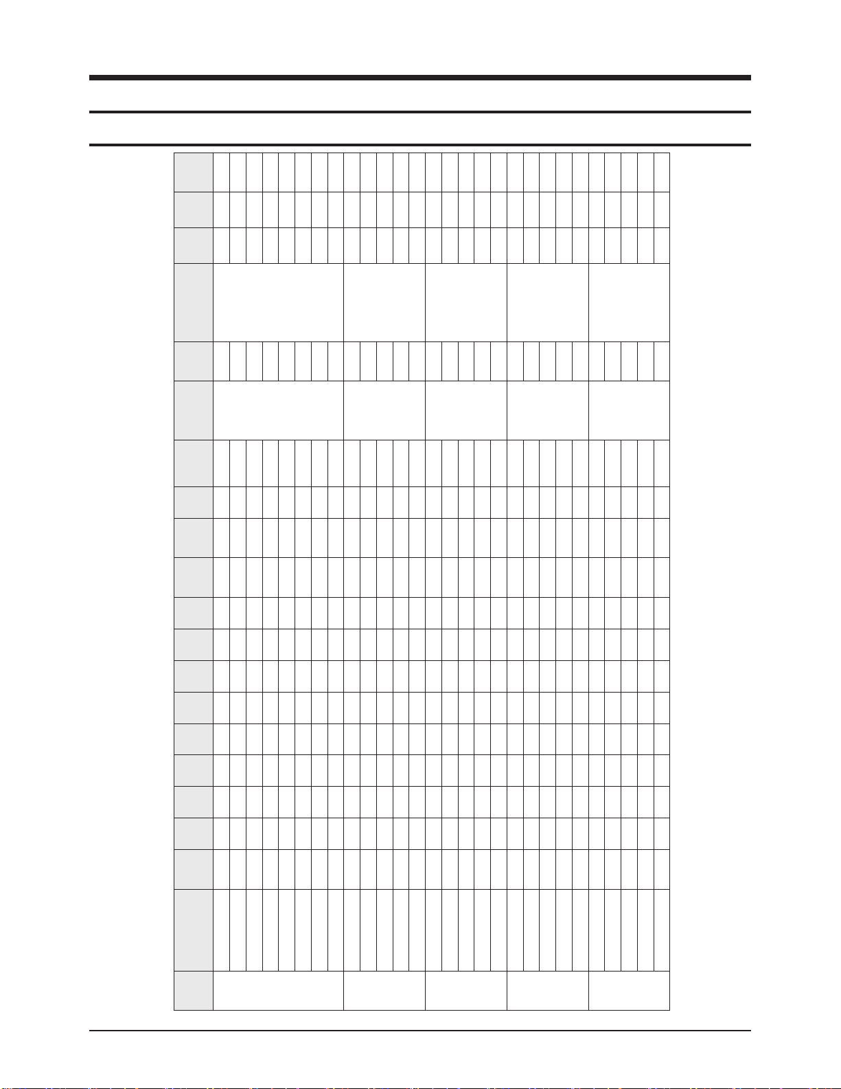
14-1 Option Byte
Green
KS7B
Model
VOLT
Master
S/W
Tact
S/W
Tilt VM
PIP X-Ray
DNIe
-Jr
21"
Ear-
Phone
BACK
S-VIDEO
SIDE
S-VIDEO
LNA
A/V
Multi
(Philippine)
Remocon
(AA59-)
Sound
Output
Micom
Energy
Star
TIMER/
ST-BY
Remark
Korea
CT-29K10V
AC220V
0 x x x x X x
X 0
X X X
TM75
00317A
7W x2
AA97-16044A
T_TGNNKU_1000
X ST-BY
CT-29M20V
AC220V
0 x x x x X
x
X 0 X X X
7W x2
X ST-BY
CT-29M16V
AC220V
0
x
x
x x
X
x
X 0
X
X
X 7W x2
X ST-BY
CT-29K12V
AC220V
0 x x x x X x x 0 X X X 7W x2 X ST-BY
CT-29K6V
AC220V
0
x
x x
x
X x
x 0 X X
X 7W x2
X ST-BY
USA
CANADA
TXR2728GX/XAA
AC120V
x 0 X x x 0
x
x 0 X X X
TM75
00316B
7W x2
AA97-16044A
T_TGNNKU_1000
O Timer
TXR2728GX/XAC
AC120V
x
0 X x
x
0 x
x 0
X
X
X
PANAMA
CL29M16MQDXXAP AC220V
x 0
X
x x 0
x
x 0 X X
X
TM75
00316B
10W x2
AA97-16044A
T_TGNNKU_1000
X Timer
MEXICO
CL29M16MQDXXAX AC120V
x
0 x
x x
x x
x 0 X X
X
TM75
00316B
10W x2
AA97-16044A
T_TGNNKU_1000
O Timer
Others
Latin
CL29M16MQDXGSU Free Volt
x
0 x
x x
x x
x 0
X X X
TM75
00316B
10W x2
AA97-16044A
T_TGNNKU_1000
X Timer
CL29M16MQDXSTR
Free Volt
x
0 x
x
x
x x x 0 X X X
10W x2
X Timer
CL29M16MQDXXAO Free Volt
x
0 x
x x
x x
x 0
X X X 10W x2
X Timer
CL29M16MQDXRCL
Free Volt
x 0 X
x
x x x x 0 X X X 10W x2 X Timer

Reference Information
14-2 Samsung Electronics
Mono
A type of audio interface that transmits audio signals through a
single channel.
Through a mono interface, it is hard to experience stereophonic
sound and sound is played only by one speaker.
Reception Sensitivity Amplification
A signal amplification technique that amplifies weak broadcasting signals by applying satellite technology to provide a better
visual quality even for users in regions where only weak broadcasting signals are available.
Stereo
A type of audio interface that transmits audio signals through 2
channels.
Stereo transmits audio signals for the right and left channels so
that you can experience stereophonic sound, and the sound is
played with 2 speakers.
English Caption
A function that shows English caption or text information included in the broadcasting signal or video tape. You can use this
function to study English by watching AFKN or CC marked
video tapes.
Video/Audio Ports
You may experience poor visual and audio quality when watching a video tape on channel 3 or 4 through the antenna cable.
You can experience better visual and audio quality connecting
the TV and VCR through the Video/Audio ports. The video port
is distinguished by the color yellow, and the audio ports are distinguished by the white (left) and red colors (right).
External Input
External Input is connecting video devices such as a VCR,
camcorder, DVD, etc. as a video source.
Satellite Broadcast
Satellite Broadcast transmits programs via satellite so that the
broadcast is viable in all areas at a high visual and sound quality. It provides approximately 100 channels including public
broadcast channels. To view satellite broadcast, you have to
install an additional receiver.
Wired Broadcast
Satellite Broadcast refers to movie, entertainment and educational programs transmitted by the broadcasting station in a
hotel or school.
Audio Multimix
Audio Multimix provides 2 languages for audio when broadcasting a foreign movie, drama, news, etc. You can select and listen to one of the supported languages or you can select and
listen to both languages simultaneously.
Component Port (Green, Blue, Red)
The Component Port separately transmits the luminance signal
and provides the best quality of all video connection types.
Cable Broadcast
Cable Broadcast transmits programs via cable instead of radio
wave. To view a cable broadcast, you need to subscribe to your
local cable broadcast service provider and install an additional
receiver.
Tuner
RF signal processing , output IF signal.
DVD (Digital Versatile Disc)
DVD is a large capacity media that can save multimedia content such as video, game, audio applications, etc. using MPEG2 video compression technology on a CD-sized disc.
S-VIDEO IN Port
This is called super video. S-Video is a type of video signal
which has the video luminance and color signals separated in
order to provide a better visual quality.
VHF/UHF
VHF refers to TV channels 2 to 13, and UHF refers to TV channels 14 to 69.
Turbo sound
Turbo sound emphasizes the bass and treble frequencies to
add fullness to the sound.
Turbo Plus : It can strength the bass while enjoying music and
movies.
Voice : It can enhance the speech signal,such as leaving clear
voice, when watching the News,Drama and Documentary etc.
14-2 Technical Terms
Circuit Description
Samsung Electronics 13-1
13. Circuit Description
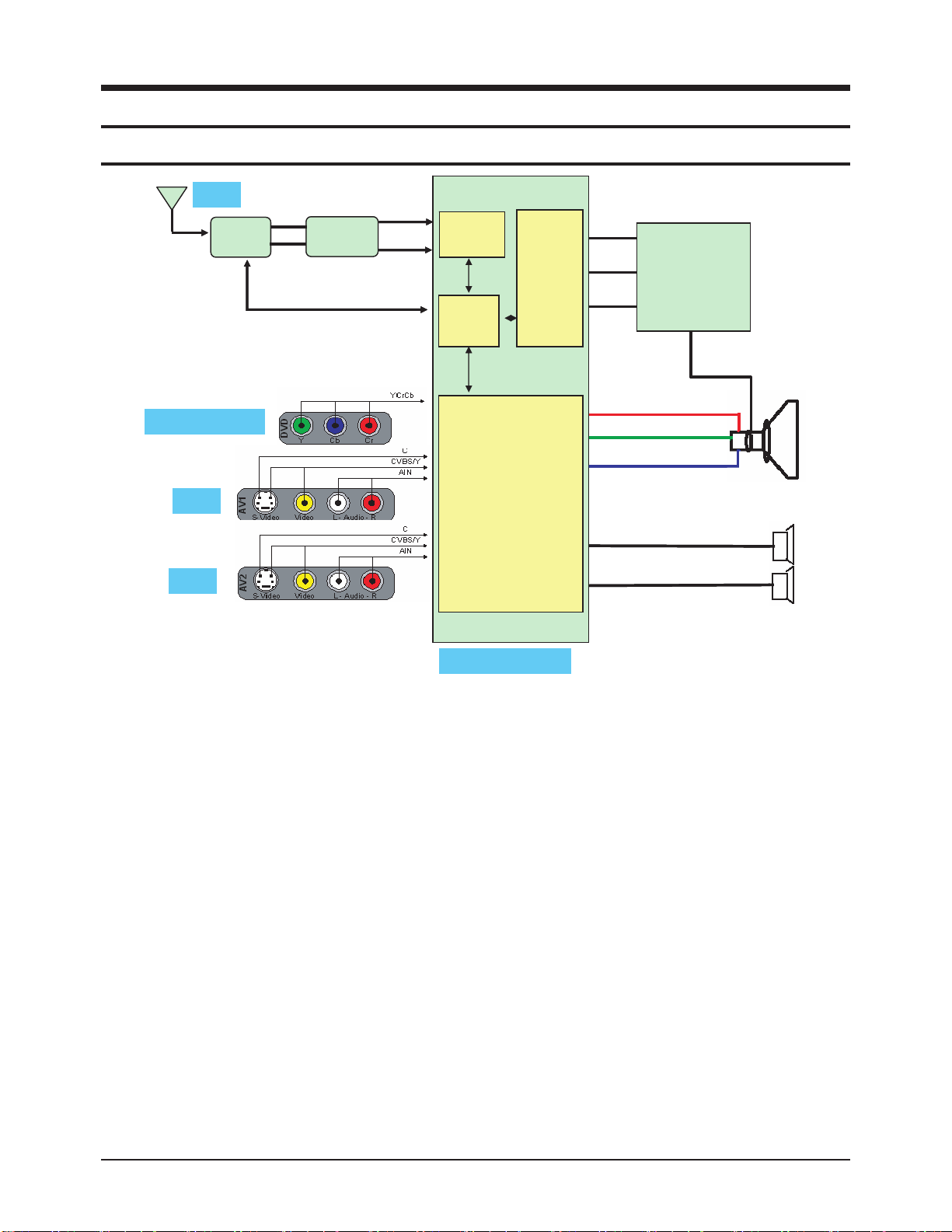
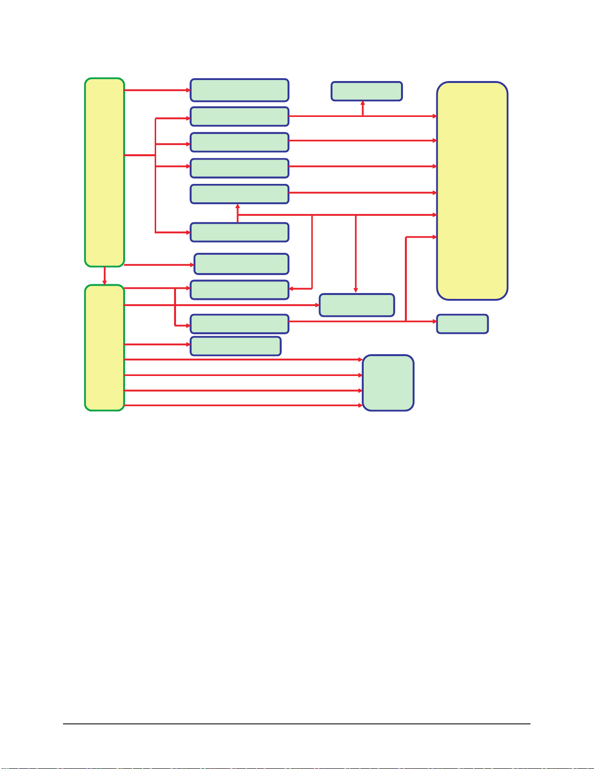
13-1 Overall Block Description
* The functional part of a direct view type TV consists of the System, Deflection and Power parts.
* The Assy's are classified by the corresponding functions, by adopting GREEN CRT.
* The Power Block is different from the KS7A's in the power supply chip. STR and TRANS have been changed.
Assy's has been changed too.
* The System Block is looked similar to that for the existing model (KS7A).
* The AV signal is input through the AV port and Side AV port of the System Block.
* The audio signal is processed as same as for KS7A'S.
* Micom Block is same as the KS7A'S in the hartware. But it is different from KS7A'S in the software.
* The Deflection Block is consists of the CRT Driver part of the System Block, the CRT Assy part and the Deflection Block controls
the all of the deflection.
* Micom Block consists of five aspects as: Video & Sound IF Processor,Sound Processor, Video Processor, Display and Deflection
Processor and Controller, OSD,Text Processing.
* TDQ-6F/13F2S (Tuner): RF signal processing, output IF signal.
ANT
ANT
Saw Filter
Tuner
Tuner
COMPONENT
COMPONENT
AV1
AV1
Saw Filter
I2C
I2C
IFIN+
IFIN+
IFIN -
IFIN -
Video
Video
Sound IF
Sound IF
2
2
C
C
I
I
Controller
Controller
2
2
I
I
C
C
Video Audio
Video Audio
Processing
Processing
Display
Display
Deflection
Deflection
Hout
Hout
Vert
Vert
EW
EW
Deflection Block
Deflection Block
(HTR &
(HTR &
Vertical AMP)
Vertical AMP)
H/V
H/V
R
R
G
G
B
B
L
L
R
AV2
AV2
MICOM BLOCK
MICOM BLOCK
R
Circuit Description
13-2 Samsung Electronics
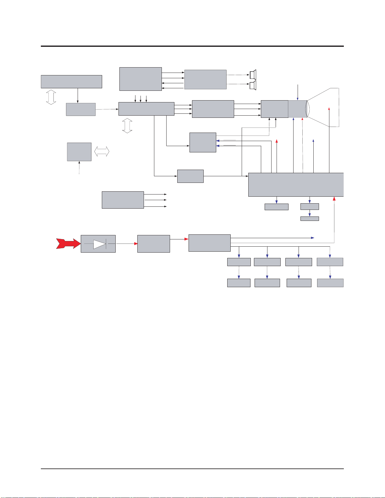
13-2 Partial Block Description
13-2-1 System Board Block Description
* VCT4953: DRX+VSP+MSP+TVT. It contains the entire IF, audio, video, display and deflection processing for 4:3 and 16:9
50/60Hz mono and stereo TV sets. The integrated microcontroller is supported by a powerful OSD generator with integrated
Teletext and CC acquisition including on-chip page memory.
* 2SC5936: Inputed H-DRIVE signal which comes from VCT4953.It amplify the H-DRIVE then output to Deflection Yoke.
* LA78045: Inputed VDP signal which comes from VCT4953.It amplify the VDP then output to Deflection Yoke.
* TDA7266SA/TDA7297SA: It is a dual channel audio amplifier.The two audio signals L and R input to it and are amplified, then
output to speaker.
* TDA6109JF: It includes three video output amplifiers and is intended to drive the three cathodes of a color CRT directly.
The output R
、G、B signals will connect to the CRT socket pins directly.
* EEPROM: As a extended ROM of TVT. It contains some data which is used to program executing.
* STR W6750F: SMPS control HIC. Provide switching signal in order to control the trans working.
* TDQ-6F/13F2S(TUNER): Receives the RF signal and output a fixed IF to Micom.
SCL SDA
Tuner
PRE-AMP
EEPROM
24C161
A+5.0V
HC101
IC902
FROM
IF-OUT
JAR701
EXTERNAL A/V
INPUT/OUTPUT
TERMINAL AUDIO
PART (RCA)
FROM EXTERNAL TERMINAL
Y Pb Pr
ICV201 VCTI
VCT49X X
DRX+VSP+DDP+MSP+Micom
SCL SDA
SCL
SDA
DVD_SVHS
EXTERNAL DVD
INPUT TERMINAL
(RCA)
H-DRIVE /IN
Pr
Pb
Y
IC801S
STR W6750F
A-1-IN
A-2-IN
A-1-OUT
A-2-OUT
VDP IN
2SC5936
ICV201 Y/Pb/Pr
INPUT PORT
Q401
IC602
TDA7266SA/
TDA7297SA
IC501
TDA6109JF
IC301
LA78045
T801S
Switch Trans
V-AMP/ OUT
+16.5V
-16.5V
H.V/OUT
A-L-OUT
A-R-OUT
R-DRIVE /OUT
G-DRIVE/OUT
B-DRIVE/OUT
TO SOUND AMP VCC 14V
TO FBT VCC 125V
CRT&D-YORK
H.V/OUT
TO IC501
VCC 200V
FBT FUH29A001G
TUNER 33V
FROM HEAT ER
S
C
F
R
O
E
C
E
U
N
S
V
V
O
O
L
L
T
T
A
A
G
G
E
E
KAC2231
B+8V
H
I
G
H
V
H
O
L
E
A
T
A
T
E
G
E
R
125V
KA78R05
B+5V
KA78RM33
A+3.3V
KSC2331
A+5V B+3. 3V
KSC2331
Circuit Description
Samsung Electronics 13-3
13-2-2 Power Block
AMP14V
AMP14V
S
S
M
M
P
P
S
S
130V
130V
6V
6V
14V
14V
± 16.5V
± 16.5V
B+33V
B+33V
Audio AMP
Audio AMP
Q810(KSC2331-Y)
Q810(KSC2331-Y)
Q811(KSC2331-Y)
Q811(KSC2331-Y)
Q812A(78RM33)
Q812A(78RM33)
QV905(KSC1008Y)
B+5V
B+5V
IC802(78R05)
IC802(78R05)
HTR
HTR
Vertical AMP
Vertical AMP
A+5V
A+5V
B+3.3V
B+3.3V
A+3.3V
A+3.3V
A+1.8V
A+1.8V
B+5V
B+5V
EEPROM
EEPROM
B+5V
B+5V
TUNER
TUNER
MICOM
MICOM
FBT
FBT
B+210V
B+210V
Q813(KSC2331-Y) EW
Q813(KSC2331-Y) EW
Video AMP
Video AMP
H/V
H/V
SCREEN
SCREEN
FOCUS
FOCUS
HEATER
HEATER
B+8V
B+8V
CRT
CRT
Circuit Description
13-4 Samsung Electronics
■ Main Board
Items Descriptions Remarks
MICOM VCT4953_F1 Micronas
Tuner TECC1040SL32A(E),XUGUANG
BRIDGE DIODE GSIB460,VISHAY
Trans Switching 42B135,DK
STR STR-W6750F,SANKEN
FET FQP630TSTU,FAIRCHILD
Vertical DEF. LA78045,SANYO
Horizontal DEF. 2SC5936M,MATSUSHITA
SOUND AMP TDA7297SA, SGS-TOMSON 10W+10W
SOUND AMP TDA7266SA, SGS-TOMSON 7W+7W
EEPROM 24C161,SAMSUNG
VIDEO AMP TDA6109JF, Philips
Regulator 78R05 B+5V Regulator
Regulator 78RM33 A+3.3V Regulator
Regulator KSC2328A-Y A+5V Regulator
Regulator KSC2331-Y B+3.3V Regulator
13-2-3 IC Line Up

Alignment & Adjustment
Samsung Electronics 3-1
3. Alignment & Adjustment
3-1 Service Instruction
1. General Adjustment :
In general, a color TV can provide ideal visual quality by adjusting the basic settings such as the vertical size, horizontal size,
focus, etc.
Display a black and white picture on the screen to check if the picture is clearly displayed.
If there are some 'spotted' points on the screen when displaying a black and white picture, degauss the screen using the
degauss coil. If the spotted points remain, re-adjust the purity and the convergence. This completes the basic performance
examination.
Notice.
■ These adjustments and the check list are only applied to KS7D chassis-applied models.
■ North America use 110V, South Central America use 220v for the measurement set.
It is recommended using an insulation transformer when supplying power to the set so as to prevent shock to the set
or to yourself.
■ These adjustment specifications have been created on the basis of the domestic KS7D chassis-applied remote
control model. Some of the contents may be changed subject to the sales location and the product specifications.
2. When replacing the Main Board :
Focus adjustment, screen voltage setting and W/B adjustment are all required.
3. When replacing the CRT Ass'y : No adjustments required.
4. When replacing the Side AV : No adjustments required.
Alignment & Adjustment
3-2 Samsung Electronics
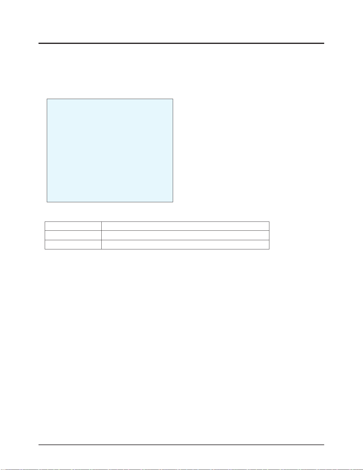
3-2 How to Access Service Mode
MENU Show all menus
▲ / ▼
Move the cursor to select an item.
◀ / ▶
Adjust the selected configuration value
1. To enter Service Mode, press the keys on the remote control according to the following sequence. (in Stand-by status)
Mute → 1 → 8 → 2 → Power On
※ When failing to enter Service Mode, repeat the procedure above.
2. The initial screen of Service Mode.
3. Functions of the Keys within Service Mode
Deflection
Video Adujst1
Video Adujst2
Video Adujst3
OPTION
OPTION2
YC DELAY
TEST PATTERN
EEPROM
BUS STOP
CHCKSUM
RESET
G2 ADJUST

Alignment & Adjustment
Samsung Electronics 3-3
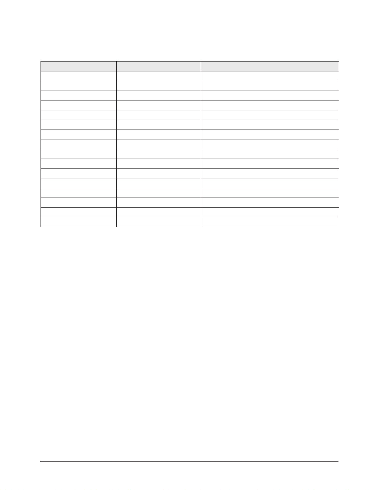
3-3 Factory Data
★ The underlined are items applied during the service adjustment. None of the others should be adjusted.
1. Deflection(NT 60Hz)
No Item Remark
29" SLIM 29" SLIM
CL-29Z30PQ CL-29Z30MQ
1 V Amp ADJ 42 42
2 V Shift ADJ -24 -24
3 H EW ADJ -6 -6
4 H Shift ADJ 130 130
5 V Linearity ADJ -3 -3
6 V SC FIX 43 43
7 H Parabola ADJ 78 78
8 Upper Corner ADJ 11 11
9 Lower Corner ADJ -29 -29
10 Upper Corner6 FIX -18 -18
11 Lower Corner6 FIX 3 3
12 H Trapezium ADJ 29 29
13 Bow ADJ 2 2
14 Angle FIX -1 -1
15 EHT Time FIX 20 20
16 EHT Threshold FIX 1 1
17 EHT Vertical FIX 0 0
18 EHT Horizontal FIX 24 24
19 EHT Vertical2 FIX 4 4
20 EHT Horizontal2 FIX 7 7
 Loading...