

Samsung CL-21S8MQ, CT-17M6MQ, CL-29M16, CL-17K10MJZ, CL-29T21PQ User Manual
Owner’s
Instructions
COLOR TELEVISION
...........................................................................................................................
.............
AA68-03258B-0 0
CL29A10
CL34A10
CL29M6
CL21S8MQU
CL25M6MQU
CL29M6MQU
CL29M16MQU
CL29K5MQU

2
Important Warranty Information
Regarding Television Format
Viewing
Standard screen format televisions (4:3, the aspect ratio of the screen width to height) are
primarily designed to view standard format full-motion video. The images displayed on
them should primarily be in the standard 4:3 ratio format and constantly moving.
Displaying stationary graphics and images on screen, such as the dark top and bottom
letterbox bars (wide screen pictures), should be limited to no more than 15% of the total
television viewing per week.
Wide screen format televisions (16:9, the aspect ratio of the screen width to height) are
primarily designed to view wide screen format full-motion video. The images displayed
on them should primarily be in the wide screen 16:9 ratio format, or expanded to fill the
screen if your model offers this feature, and constantly moving. Displaying stationary
graphics and images on screen, such as the dark side-bars on non-expanded standard
format television video and programming, should be limited to no more than 15% of the
total television viewing per week.
Additionally, viewing other stationary images and text such as stock market reports,
video game displays, station logos, web sites or computer graphics and patterns, should
be limited as described above for all televisions. Displaying any stationary images that
exceed the above guidelines can cause uneven aging of picture tubes (CRTs) that leave subtle,
but permanent burned-in ghost images in the television picture. To avoid this, vary the programming
and images, and primarily display full screen moving images, not stationary patterns or
dark bars. On television models that offer picture sizing features, use these controls to
view the different formats as a full screen picture.
Be careful in the selection and duration of television formats used for viewing. Uneven
CRT aging as a result of format selection and use, as well as other burned-in images, is
not covered by your Samsung limited warranty.

CONTENTS
3
Chapter 1: Your New TV . . . . . . . . . . . . . . . . 5
List of Features . . . . . . . . . . . . . . . . . . . . . . . . . . . . . . . . . . . . . . . . . . . 5
Familiarizing Yourself with The TV . . . . . . . . . . . . . . . . . . . . . . . . . . . . 6
Front Panel Buttons . . . . . . . . . . . . . . . . . . . . . . . . . . . . . . . . 6
Side Panel Jacks . . . . . . . . . . . . . . . . . . . . . . . . . . . . . . . . . . . 7
Rear Panel Jacks . . . . . . . . . . . . . . . . . . . . . . . . . . . . . . . . . . . 8
Remote Control. . . . . . . . . . . . . . . . . . . . . . . . . . . . . . . . . . . . 9
Chapter 2: Installation . . . . . . . . . . . . . . . . . 11
Connecting VHF and UHF Antennas . . . . . . . . . . . . . . . . . . . . . . . . . 11
Antennas with 300-ohm Flat Twin Leads . . . . . . . . . . . . . . . 11
Antennas with 75-ohm Round Leads . . . . . . . . . . . . . . . . . . 12
Separate VHF and UHF Antennas. . . . . . . . . . . . . . . . . . . . . 12
Connecting Cable TV . . . . . . . . . . . . . . . . . . . . . . . . . . . . . . . . . . . . . 12
Cable without a Cable Box . . . . . . . . . . . . . . . . . . . . . . . . . . 12
Connecting to a Cable Box that Descrambles All Channels . . 13
Connecting to a Cable Box that Descrambles Some Channels13
Connecting a VCR. . . . . . . . . . . . . . . . . . . . . . . . . . . . . . . . . . . . . . . . 14
Connecting an S-VHS VCR. . . . . . . . . . . . . . . . . . . . . . . . . . 16
Connecting a Second VCR to Record from the TV. . . . . . . . . 17
Connecting a DVD Player . . . . . . . . . . . . . . . . . . . . . . . . . . . . . . . . . . 17
Connecting a Camcorder. . . . . . . . . . . . . . . . . . . . . . . . . . . . . . . . . . . 18
Installing Batteries in the Remote Control. . . . . . . . . . . . . . . . . . . . . . 19
Chapter 3: Operation . . . . . . . . . . . . . . . . . . 20
Turning the TV On and Off. . . . . . . . . . . . . . . . . . . . . . . . . . . . . . . . . 20
Plug & Play Feature . . . . . . . . . . . . . . . . . . . . . . . . . . . . . . . . . . . . . . 20
Viewing the Menus and On-Screen Displays. . . . . . . . . . . . . . . . . . . . 22
Viewing the Menus. . . . . . . . . . . . . . . . . . . . . . . . . . . . . . . . 22
Viewing the Display . . . . . . . . . . . . . . . . . . . . . . . . . . . . . . . 22
Selecting a Menu Language. . . . . . . . . . . . . . . . . . . . . . . . . . . . . . . . . 23
Memorizing the Channels . . . . . . . . . . . . . . . . . . . . . . . . . . . . . . . . . . 24
Selecting the Video Signal-source . . . . . . . . . . . . . . . . . . . . . 24
Storing Channels in Memory (Automatic Method) . . . . . . . . 25
Adding and Erasing Channels (Manual Method). . . . . . . . . . 26
Changing Channels. . . . . . . . . . . . . . . . . . . . . . . . . . . . . . . . . . . . . . . 27
Using the Channel Buttons . . . . . . . . . . . . . . . . . . . . . . . . . . 27
Directly Accessing Channels . . . . . . . . . . . . . . . . . . . . . . . . . 27
Using the PRE-CH Button to select the Previous Channel. . . 27
Labeling the Channels. . . . . . . . . . . . . . . . . . . . . . . . . . . . . . . . . . . . . 28
Adjusting the Volume . . . . . . . . . . . . . . . . . . . . . . . . . . . . . . . . . . . . . 29
Using the Mute Button . . . . . . . . . . . . . . . . . . . . . . . . . . . . . 29
Setting the Clock. . . . . . . . . . . . . . . . . . . . . . . . . . . . . . . . . . . . . . . . . 30
Customizing the Picture . . . . . . . . . . . . . . . . . . . . . . . . . . . . . . . . . . . 31
Using Automatic Picture Settings . . . . . . . . . . . . . . . . . . . . . . . . . . . . 32
Customizing the Sound. . . . . . . . . . . . . . . . . . . . . . . . . . . . . . . . . . . . 33
Using Automatic Sound Settings. . . . . . . . . . . . . . . . . . . . . . . . . . . . . 34
Setting the Blue Screen Mode . . . . . . . . . . . . . . . . . . . . . . . . . . . . . . . 35
Setting The On/Off Melody. . . . . . . . . . . . . . . . . . . . . . . . . . . . . . . . . 36
Viewing an External Signal Source . . . . . . . . . . . . . . . . . . . . . . . . . . . 37
Setting the Signal Source. . . . . . . . . . . . . . . . . . . . . . . . . . . . 37
Assigning Names to External input mode . . . . . . . . . . . . . . . 38

CONTENTS
4
Chapter 4: Special Features. . . . . . . . . . . . . 39
Changing the Color Tone . . . . . . . . . . . . . . . . . . . . . . . . . . . . . . . . . . 39
Changing the Screen Size . . . . . . . . . . . . . . . . . . . . . . . . . . . . . . . . . . 40
Digital Noise Reduction . . . . . . . . . . . . . . . . . . . . . . . . . . . . . . . . . . . 41
DNIe JrTM(Digital Natural Image engine) . . . . . . . . . . . . . . . . . . 42
Tilt . . . . . . . . . . . . . . . . . . . . . . . . . . . . . . . . . . . . . . . . . . . . . . . . . . . 43
Using the R.Surf Feature . . . . . . . . . . . . . . . . . . . . . . . . . . . . . . . . . . . 44
Choosing a Multi-Channel Sound (MTS) Soundtrack . . . . . . . . . . . . . 45
Extra sound settings (Auto Volume, Turbo Sound or Pseudo Stereo). . 46
LNA (Low Noise Amplifier). . . . . . . . . . . . . . . . . . . . . . . . . . . . . . . . . 47
Setting the On/Off Timer. . . . . . . . . . . . . . . . . . . . . . . . . . . . . . . . . . . 48
Setting the Sleep Timer. . . . . . . . . . . . . . . . . . . . . . . . . . . . . . . . . . . . 49
Setting the Preferred Volume Level . . . . . . . . . . . . . . . . . . . . . . . . . . . 50
Viewing Closed Captions . . . . . . . . . . . . . . . . . . . . . . . . . . . . . . . . . . 51
Viewing Picture-in-Picture
. . . . . . . . . . . . . . . . . . . . . . . . . . . . . . . . . . . 52
Activating Picture-in-Picture. . . . . . . . . . . . . . . . . . . . . . . . . 52
Selecting a Signal Source (External A/V) for PIP . . . . . . . . . . 53
Swapping the Contents of the PIP image and Main image. . . 54
Changing the Position of the PIP Window . . . . . . . . . . . . . . 55
Changing the PIP Channel . . . . . . . . . . . . . . . . . . . . . . . . . . 56
Changing the Size of the PIP Window. . . . . . . . . . . . . . . . . . 57
Viewing the Demonstration. . . . . . . . . . . . . . . . . . . . . . . . . . . . . . . . . 58
Customizing Your Remote Control . . . . . . . . . . . . . . . . . . . . . . . . . . . 59
Chapter 5: Troubleshooting. . . . . . . . . . . . . 61
Identifying Problems. . . . . . . . . . . . . . . . . . . . . . . . . . . . . . . . . . . . . . 61
Appendix . . . . . . . . . . . . . . . . . . . . . . . . . . . . 62
Cleaning and Maintaining Your TV . . . . . . . . . . . . . . . . . . . . . . . . . . . 62
Using Your TV in Another Country. . . . . . . . . . . . . . . . . . . . . . . . . . . 62
Specifications . . . . . . . . . . . . . . . . . . . . . . . . . . . . . . . . . . . . . . . . . . . 63

YOUR NEW TV
5
Chapter One
YOUR NEW TV
List of Features
Your TV was designed with the latest technology. This TV is a high-performance unit that
includes the following special features:
• Full Flat Screen
• Easy-to-use remote control
• Easy-to-use on-screen menu system
• Automatic timer to turn the TV on and off
• Adjustable picture and sound settings that can be stored in the TV’s memory
• Automatic channel tuning for up to 181 channels
• A special filter to reduce or eliminate reception problems
• A built-in multi-channel sound decoder for stereo and bilingual listening
• Built-in, dual channel speakers
• A special sleep timer
• Picture in Picture (CL29A10/CL34A10/CL29M6)
YOUR NEW TV
6
Familiarizing Yourself with The TV
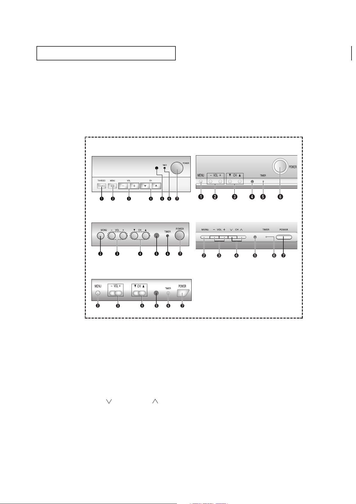
Front Panel Buttons
The buttons on the front panel control your TV’s basic features, including the on-screen
menu. To use the more advanced features, you must use the remote control.
Œ
TV/VIDEO
Press to change bet ween viewing TV programs
and signals from other components.
´
MENU
Press to see an on-screen menu of your TV's features.
ˇ
VOL – and +
Press to increase or decrease the
volume. Also used to select items on the onscreen menu.
¨
CH (▼) and CH (▲)
Press to change channels. Also press to select
various items on the on-screen menu.
ˆ
Remote Control Sensor
Aim the remote control towards this spot on the
TV.
Ø
TIMER indicator
When the TV is turned on, the TIMER indicator
blinks five times. This indicator illuminates when
the TIMER mode is set to the “On” position after
setting the clock and either the On timer or Off
timer, with the remote control.Even if the power is
turned off, this indicator stays lit. (Clock must be
set before using this function.)
∏
POWER
Press to turn the TV on and off.
CL29A10/CL34A10
CL29M6/CL25M6MQU/CL29M6MQU
CL29K5MQU CL29M16MQU
CL21S8MQU
YOUR NEW TV
7
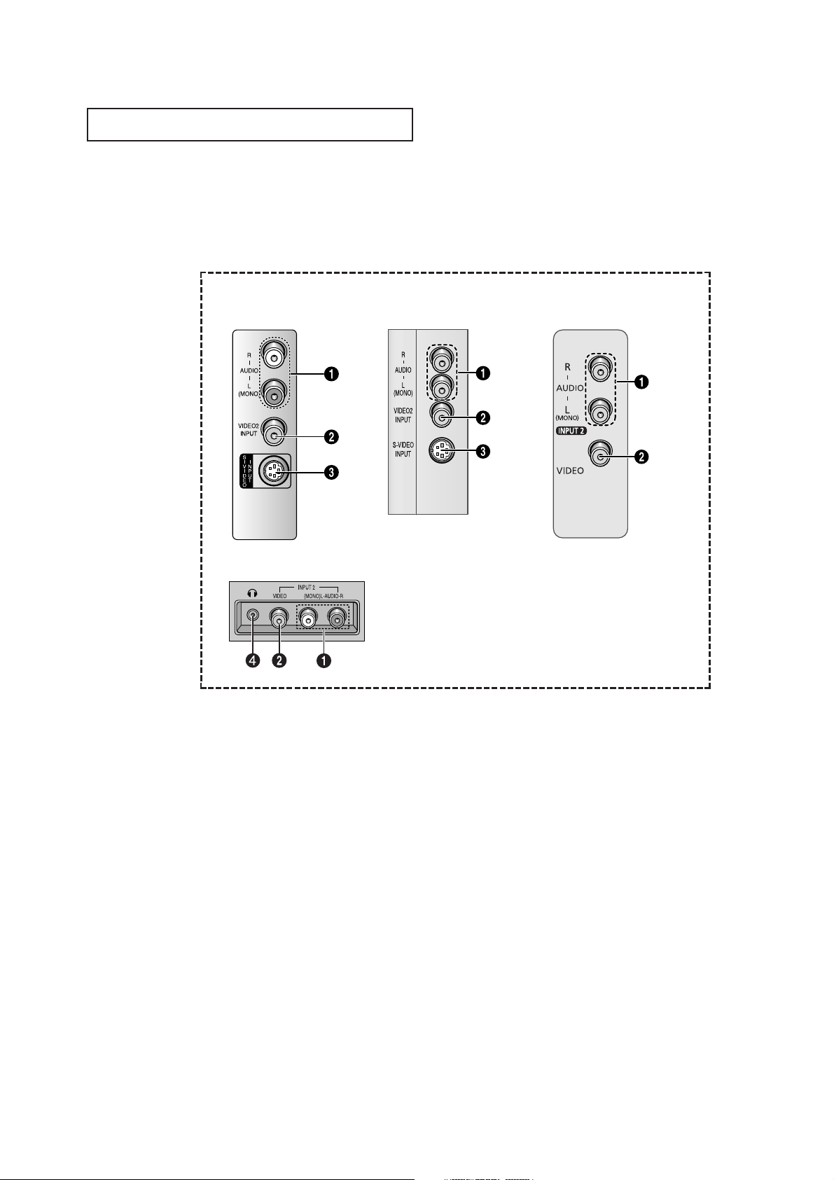
Side Panel Jacks
You can use the side panel jacks to connect an A/V component that is used only occasionally, such as a camcorder or video game. (For information on connecting equipment,
see pages 11 ~ 18.)
CL29A10
CL34A10
Œ
AUDIO INPUT jacks
Used to connect t he audio
signals from a camcorder or video game.
´
VIDEO INPUT jack
Used to connect a video signal from
a camcorder or video game.
ˇ
SUPER VIDEO INPUT jack
S-Video signal from an S-VHS VCR or DVD
player.
Note: In S-Video mode, Audio Output depends what
kind of audio input source is connected to the side
audio input jacks (AV2).
¨
HEADPHONE
Connect a set of external headphones to this jack for
private listening.
CL29M6
CL25M6MQU/CL29M6MQU
CL29K5MQU/CL29M16MQU
CL21S8MQU
YOUR NEW TV
8
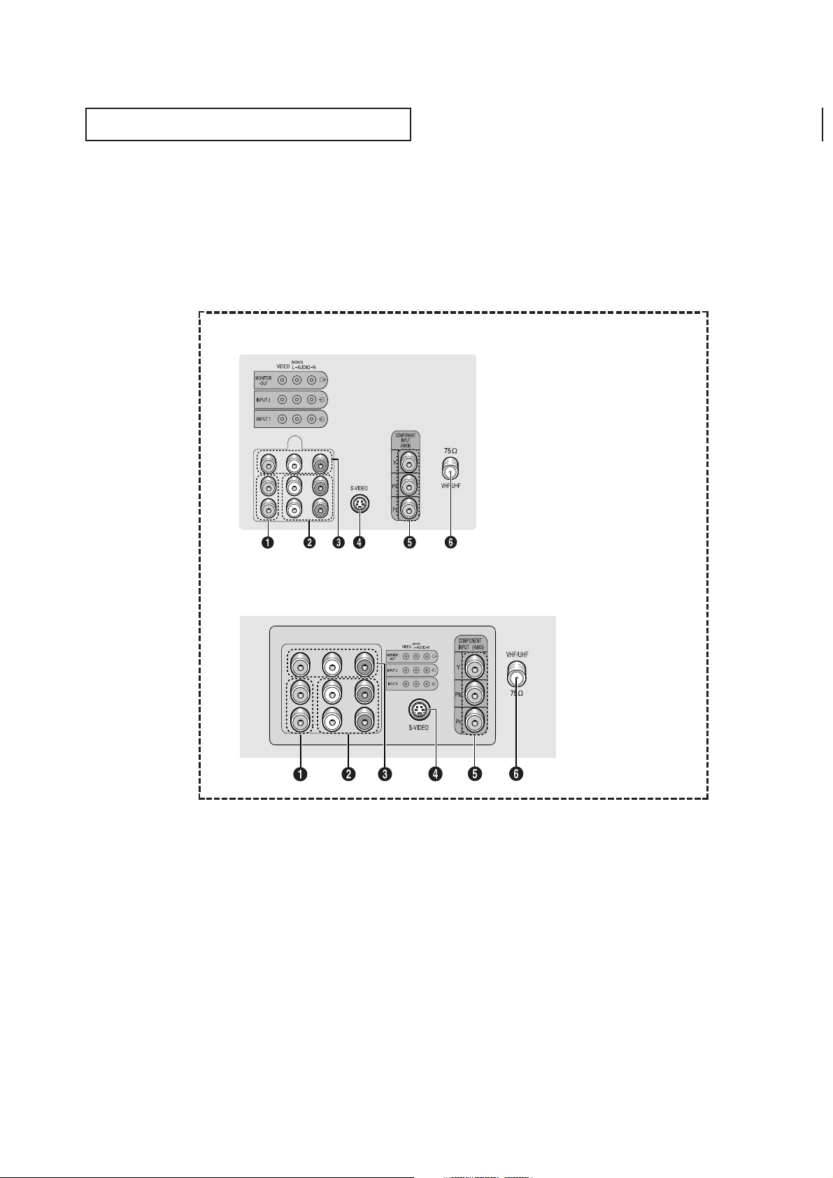
Rear Panel Jacks
Use the rear panel jacks to connect an A/V component that will be connected
continuously, such as a VCR or a DVD player.
Because there are two sets of input jacks, you can connect two different A/V
components (i.e., a VCR and a DVD, 2 VCRs, etc.)
For more information on connecting equipment, see pages 11 – 18.
Œ
VIDEO INPUT jack
Video signals from VCRs, DVD players and similar
devices.
´
AUDIO INPUTS (INPUT1
and 2)
/DVD AUDIO INPUTS
(INPUT 2)
Audio signals from VCRs, DVD players and similar
devices.
Use these jacks to connect the audio signals from a
DVD player when using the DVD video input jacks.
When not using the DVD jacks, these audio jacks
function as audio for Video 2 or S-VIDEO.
ˇ
AUDIO-VIDEO MONITOR
OUTPUT jacks
These audio-video signals are identical to A/V
signals being displayed on the big screen. (Typically
used as the input signals for a recording VCR.)
¨
SUPER VIDEO INPUT jack
S-Video signal from an S-VHS VCR or DVD player.
Note: In S-Video mode, Audio Output depends what
kind of audio input source is connected to the side
audio input jacks (AV2).
ˆ
COMPONENT VIDEO INPUT
jacks
Connect video from a DVD player.
Note: Only black and white signals are output from
a monitor in DVD mode.
Ø
VHF/UHF
Connect to an antenna or to a cable TV system.
CL29M6/CL29K5MQU/CL29M16MQU/
CL25M6MQU/CL29M6MQU/CL21S8MQU
CL29A10/CL34A10
YOUR NEW TV
9
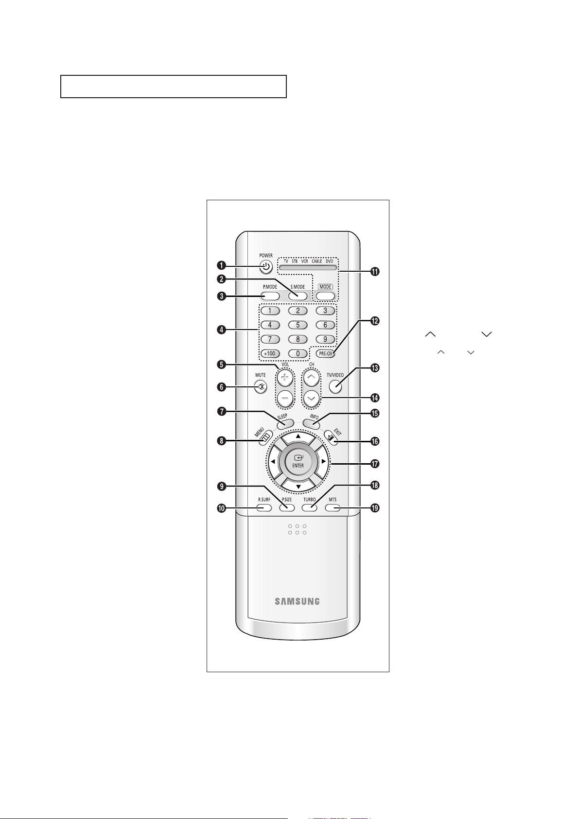
Remote Control
You can use the remote control up to about 23 feet from the TV. When using the remote,
always point it directly at the TV.
You can also use your remote control to operate your VCR, DVD and cable box. See page
59 for details.
Œ
POWER
Turns the TV on and off.
´
S.MODE
Adjust the TV sound by selecting
one of the preset factory settings
(or select your personal, customized
sound settings).
ˇ
P.MODE
Adjust the TV picture by selecting
one of the preset factory settings
(or select your personal, customized
picture settings).
¨
Number buttons
Press to select channels directly on
the TV.
+100
Press to select channels over 100.
For example, to select channel 121,
press “+100”, then press “2” and “1”.
ˆ
VOL - and VOL +
Press to increase or decrease the
volume.
Ø
MUTE
Press to temporarily cut off
the sound.
∏
SLEEP
Press to select a preset time interval for automatic shutoff.
”
MENU
Displays the main on-screen menu.
’
P.SIZE
Press to change the screen size.
˝
R.SURF
Press the R.SURF button to automatically return to a preferred
channel after a user-preset time
delay.
Ô
MODE
Selects a target device to be controlled by the Samsung remote control (i.e., TV, Set Top Box, VCR, Cable
box, or DVD).
PRE-CH
Tunes to the previous channel.
Ò
TV/VIDEO
Press to display all of the available
video sources (i.e., AV1, AV2,
S-VIDEO, COMPONENT).
Ú
CH and CH
(Channel Up/Down)
Press CH or CH to change
channels.
Æ
INFO
Press to see the time, channel, etc.,
on-screen. Also press to exit (quit)
the menu system.
ı
EXIT
Press to exit the menu.
˜
Up, Down, Left,
Right (▲,▼,œ,√)/
ENTER
Press to select highlight up, down,
left or right. While using the onscreen menus, press ENTER to activate (or change) a particular item.
¯
TURBO
Press to select the turbo sound
On or Off.
˘
MTS (Multichannel
Television Stereo)
Press to choose stereo, mono or
Separate Audio Program (SAP
broadcast).
YOUR NEW TV
10
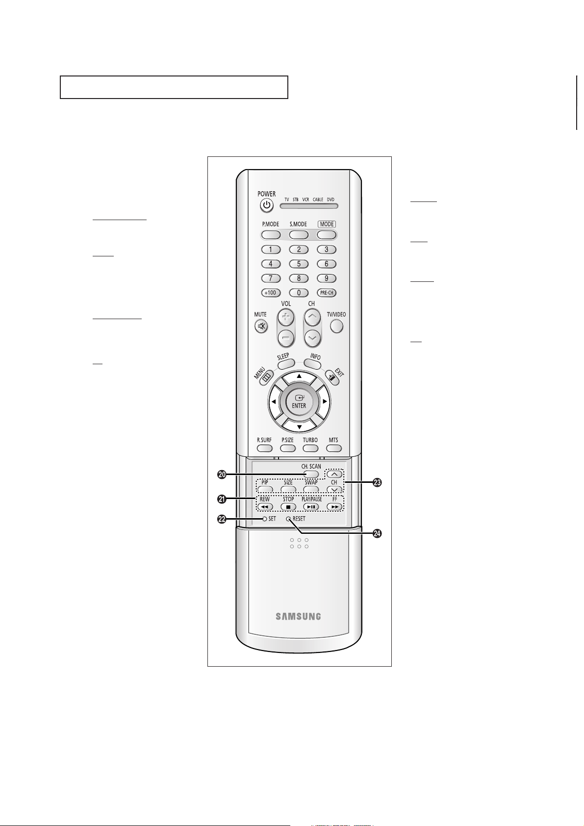
Remote Control
¿
CH. SCAN
Not available.
¸
VCR(DVD, DVR or
STB) Controls
REW (Rewind)
Press to rewind a tape in your
VCR(DVD, DVR or STB).
STOP
Press this button to stop a tape
during play, record, rewind or
fast forward. If the button is
pressed during Full-Automatic
play, the function will be can-celled.
PLAY/PAUSE
Press the PLAY/PAUSE button to
play back prerecorded tapes or
pause the tape.
FF
Press to fast forward the tape in
your VCR(DVD, DVR or STB).
˛
SET
Use this button when you are setting up your remote control to operate your Set Top Box,VCR, Cable
box or DVD.
◊
PIP Controls
(CL29A10/CL34A10/
CL29M6)
PIP ON
Press this button to control the PIP
window.
SIZE
Press to make the PIP window small
window or large window.
SWAP
Exchanges the video signal that is
currently displayed on the main
screen with the signal in the PIP
window.
CH
Displays the available channels in
sequence (These buttons change
channels in the PIP window only).
±
RESET
If your remote control is not functioning properly, take out the batteries and press the reset but ton for
about 2~3 seconds. Re-insert the
batteries and try using the remote
control again.
INSTALLATION
11
Chapter Two
INSTALLATION
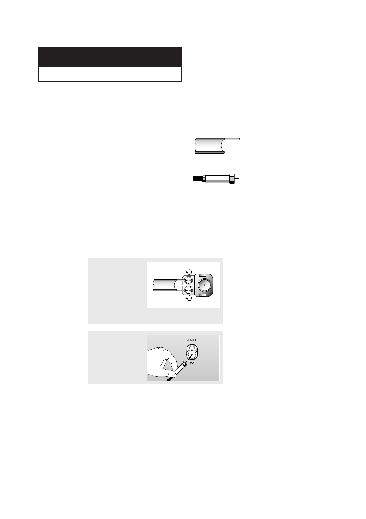
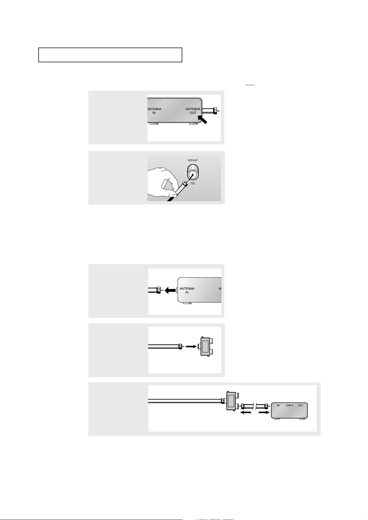
Connecting VHF and UHF Antennas
If your antenna has a set of leads that
look like this, see “Antennas with
300-ohm Flat Twin Leads” below.
If your antenna has one lead that looks
like this, see “Antennas with 75-ohm
Round Leads”, on page next.
If you have two antennas, see “Separate
VHF and UHF Antennas”, on page next.
Antennas with 300-ohm Flat Twin Leads
If you are using an off-air antenna (such as a roof antenna or “rabbit ears”) that has
300-ohm twin flat leads, follow the directions below.
1
Place the wires from
the twin leads under
the screws on the 30075 ohm adaptor (not
supplied). Use a screwdriver to tighten the
screws.
2
Plug the adaptor into
the VHF/UHF terminal
on the bottom of the
back panel.
l
INSTALLATION
12
Connecting Cable TV
To connect to a cable TV system, follow the instructions below.
Cable without a Cable Box
▼
1
Plug the incoming cable
into the VHF/UHF
antenna terminal on back
of the TV.
Because this TV is
cable-ready, you do not need a
cable box to view unscrambled cable
channels.
2
Plug the combiner into
the VHF/UHF terminal
on the bottom of the
rear panel.
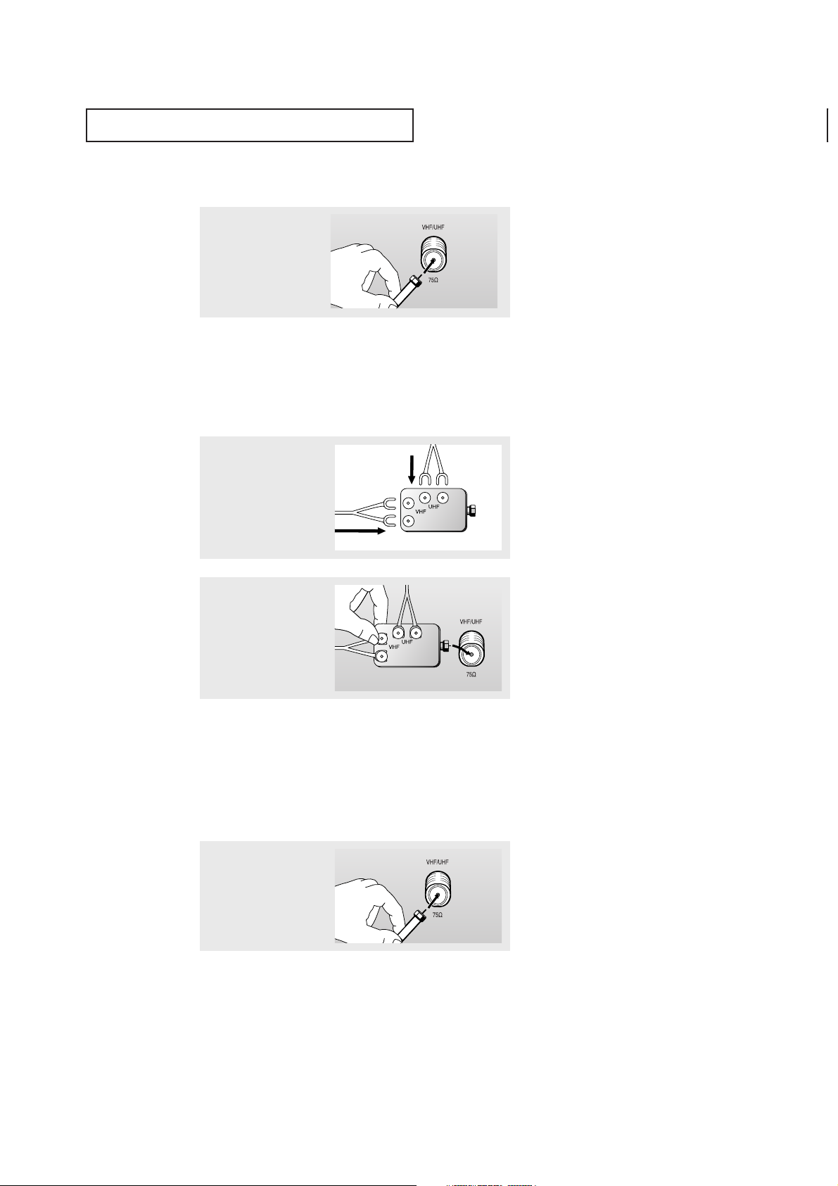
Separate VHF and UHF Antennas
If you have two separate antennas for your TV (one VHF and one UHF), you must
combine the two antenna signals before connecting the antennas to the TV. This
procedure requires a an optional combiner-adaptor (available at most electronics shops).
1
Connect both antenna
leads to t he combiner.
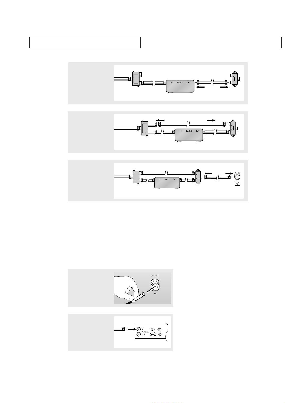
Antennas with 75-ohm Round Leads
1
Plug the antenna lead
into the VHF/UHF
terminal on the bottom of
the back panel.
INSTALLATION
13
Connecting to a Cable Box that Descrambles All Channels
▼
1
Find the cable that is
connected to the ANTENNA OUT terminal on your
cable box.
This terminal might be labeled
“ANT OUT”, “VHF OUT” or simply,
“OUT”.
2
Connect the other end of
this cable to the
VHF/UHF antenna
terminal on the back of
the TV.
Connecting to a Cable Box that Descrambles Some Channels
If your cable box descrambles only some channels (such as premium channels), follow the
instructions below. You will need a two-way splitter, an RF (A/B) switch and four lengths of
coaxial cable. (These items are available at most electronics stores.)
▼
1
Find and disconnect the
cable t hat is connected
to the ANTENNA IN
terminal on your
cable box.
This terminal might be labeled
“ANT IN”, “VHF IN” or simply,
“IN”.
2
Connect this cable to a
two-way split ter.
3
Connect a coaxial cable
between an OUTPUT terminal on the splitter and
the IN terminal on the
cable box.
Incoming Cable
Split ter
Incoming Cable
Cable Box
Split ter
INSTALLATION
14
Connecting a VCR
These instructions assume that you have already connected your TV to an antenna or a cable
TV system (according to the instructions on pages 11-13). Skip step 1 if you have not yet
connected to an antenna or a cable system.
1
Unplug the cable or
antenna from the back of
the TV.
4
Connect a coaxial cable
between the ANTENNA
OUT terminal on the cable
box and the B–IN terminal
on the RF(A/B) switch.
5
Connect another cable
between the other OUT terminal on the splitter and
the A–IN terminal on the
RF (A/B) switch.
6
Connect the last coaxial
cable bet ween the OUT
terminal on the RF (A/B)
switch and the VHF/UHF
terminal on the rear of the
TV.
After you’ve made this connection, set the A/B switch to the “A” position for normal viewing. Set the A/B switch to the “B” position to view scrambled channels. (When you set the
A/B switch to “B”, you will need to tune your TV to the cable box’s output channel, which is
usually channel 3 or 4.)
Incoming
Cable
Cable Box
RF (A/B)
Switch
Split ter
Incoming
Cable
Cable Box
RF (A/B)
Switch
Split ter
Incoming
Cable
Cable Box
RF (A/B)
Switch
TV Rear
Split ter
2
Connect the cable or
antenna to the
ANTENNA IN terminal on
the back of the VCR.
Incoming
Cable or
Antenna
VCR Rear Panel
INSTALLATION
15
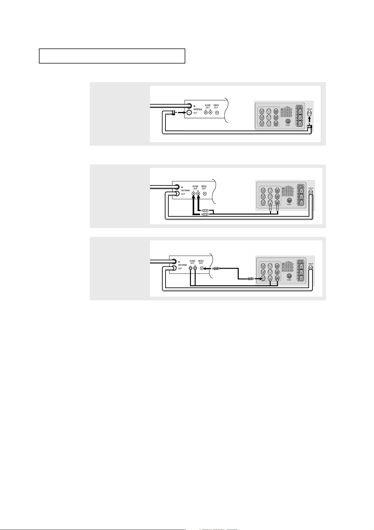
Follow the instructions in “Viewing an External Signal Source” to view your VCR tape.
Note: This figure shows the Standard connector-jack panel. The actual configuration for
your TV may be different.
3
Connect a coaxial cable
between the ANTENNA
OUT terminal on the VCR
and the antenna
terminal on the TV.
4
Connect a set of audio
cables bet ween the
AUDIO OUT jacks on the
VCR and the AUDIO jacks
on the TV.
5
Connect a video cable
between the VIDEO OUT
jack on the VCR and the
VIDEO jack on the TV.
A coaxial cable is usually included with a VCR. (If not, check your local electronics store).
VCR Rear Panel
Coaxial Cable
TV Rear Panel
VCR Rear Panel
Audio Cable
TV Rear Panel
VCR Rear Panel
Video Cable
TV Rear Panel
INSTALLATION
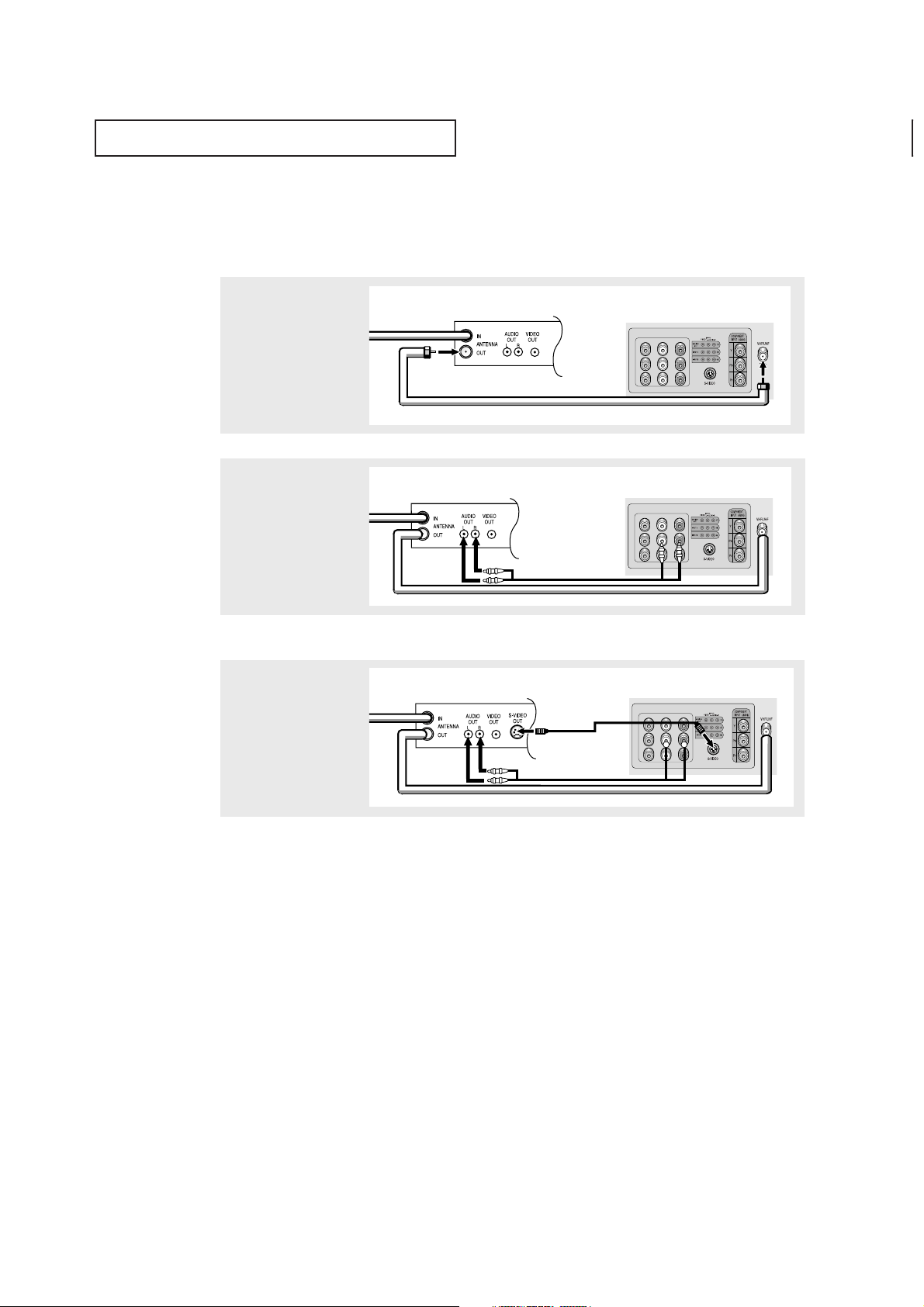
16
3
Connect an S-video
cable bet ween the
S-VIDEO OUT jack on the
VCR and the
S-VIDEO INPUT
jack on the TV.
An S-video cable is usually included with an S-VHS VCR. (If not, check your local
electronics store.)
Note: This figure shows the Standard connector-jack panel. The actual configuration for
your TV may be different.
Make sure the jacks you are using are underneath the number “2.”
2
Connect a set of audio
cables bet ween the
AUDIO OUT jacks on the
VCR and the 2 AUDIO
INPUT jacks on the TV.
1
To begin, follow steps
1–3 in the previous
section to connect the
antenna or cable to your
VCR and your TV.
Connecting an S-VHS VCR
Your Samsung TV can be connected to an S-Video signal from an S-VHS VCR. (This
connection delivers a better picture as compared to a standard VHS VCR.)
VCR Rear Panel
Coaxial Cable
TV Rear Panel
VCR Rear Panel
Audio Cable
TV Rear Panel
VCR Rear Panel
Video Cable
TV Rear Panel
INSTALLATION
17
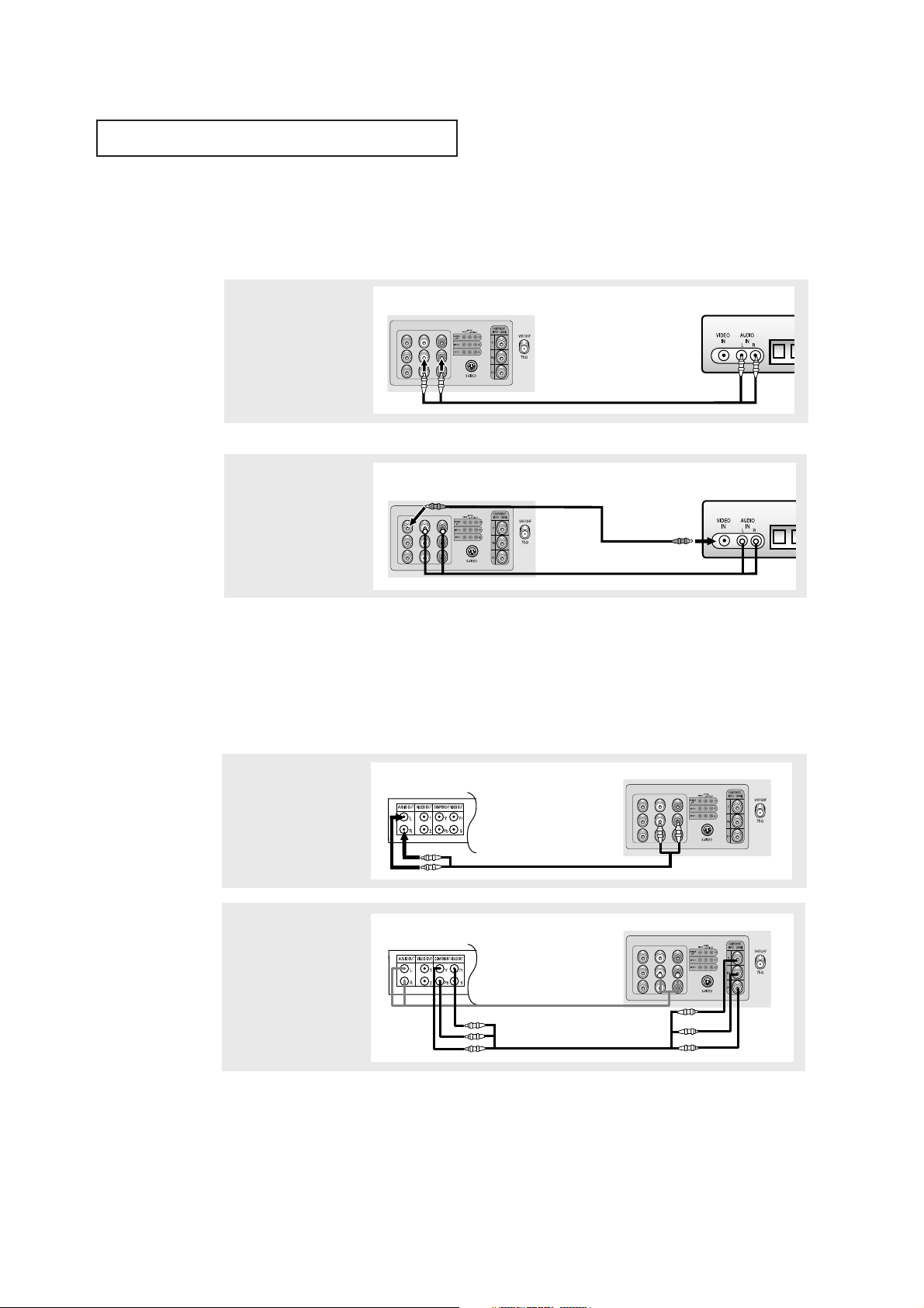
Connecting a Second VCR to Record from the TV
Your TV can send out signals of its picture and sound to be recorded by a second VCR.
To do this, connect your second VCR as follows:
1
Connect a set of audio
cables bet ween the
AUDIO OUT jacks on the
TV and the AUDIO IN
jacks on the VCR.
2
Connect a video cable
between the VIDEO OUT
jack on the TV and the
VIDEO IN jack on the
VCR.
Refer to your VCR’s instructions for more information about how to record using this kind
of connection.
(The VCR input jacks might be either on the front or on back of the VCR.)
Connecting a DVD Player
The rear panel jacks on your TV make it easy to connect a DVD player to your TV.
1
Connect a set of audio
cables bet ween the
AUDIO INPUT 2 jacks on
the TV and the AUDIO
OUT jacks on the DVD
player.
2
Connect a video cable
between t he COMPONENTINPUT(Y,Pb,Pr)
jacks on the TV and the
COMPONENT VIDEO OUT
(Y, Pb, Pr) jacks on the
DVD player.
VCR Input Panel
Audio Cable
TV Rear Panel
VCR Input Panel
Video Cable
TV Rear Panel
DVD Player Rear Panel
TV Rear Panel
Audio Cable
DVD Player Rear Panel
TV Rear Panel
Video Cable
Note: For an explanation of Component video, see your DVD player's owner's manual.
Note: This figure shows the Standard connector-jack panel. The actual configuration for
your TV may be different.
INSTALLATION
18
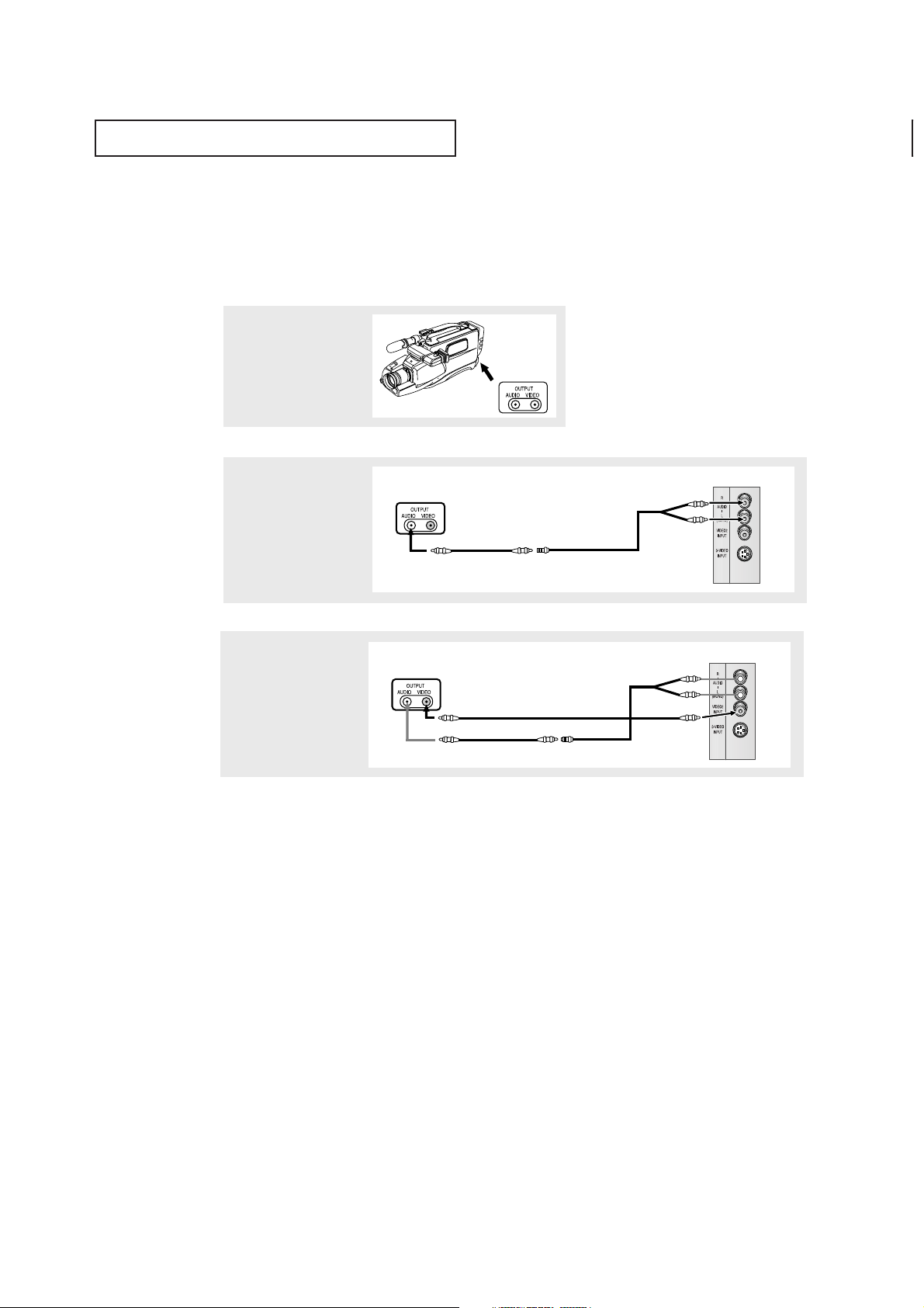
2
Connect an audio cable
between t he AUDIO
OUTPUT jack on the
camcorder and the
AUDIO terminals on t he
side of the TV.
3
Connect a video cable
between the VIDEO OUTPUT jack on the camcorder and the VIDEO terminal on the side of the
TV.
1
Locate the A/Voutput
jacks on the camcorder.
They are usually found on
the side or back of the
camcorder.
Connecting a Camcorder
The side panel jacks on your TV make it easy to connect a camcorder to your TV. They allow
you to view the camcorder tapes without using a VCR. (Also see “Viewing an External Signal
Source” on page 37)
The audio-video cables shown here are usually included with a Camcorder. (If not, check
your local electronics store.) If your camcorder is stereo, you need to connect a set of two
cables.
Note: This figure shows the Standard connector-jack panel. The actual configuration for
your TV may be different.
Camcorder
Outpu t Jacks
Camcorder
Outpu t Jacks
Audio Cable
Video Cable
Y-Connector
TV Side Panel
Camcorder
Outpu t Jacks
TV Side Panel
INSTALLATION
19
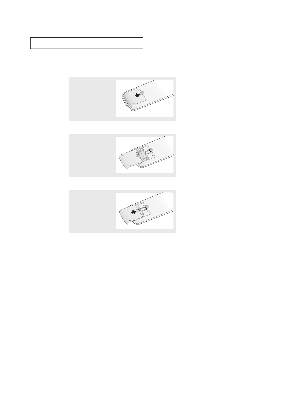
▼
3
Replace the cover.
Remove the batteries and store
them in a cool, dry place if you won’t
be using the remote control for a
long time.
The remote control can be used up
to about 23 feet from the TV.
(Assuming typical TV usage, the
batteries last for about one year.)
▼
2
Install two AAA size
batteries.
Make sure to match the “+” and
“
–” ends of the batteries with the
diagram inside the compartment.
Installing Batteries in the Remote Control
1
Slide the cover out completely.
 Loading...