

SAMSUNG CL29K5MQ2X-XAX Service Manual
COLOR TELEVISION RECEIVER
Chassis : K16A(N)_Rhumba
Model : CL29K5MQ2X/XAX
COLOR TELEVISION RECEIVER FEATURES
■■
Turbo Plus
■
DNIe jr.
■■
Low Stand-By Power Wattage
■
SOUND Equalizer
SERVICE
Manual
CL-29K5MQ

This Service Manual is a property of Samsung Electronics Co.,Ltd.
Any unauthorized use of Manual can be punished under applicable
International and/or domestic law.
© Samsung Electronics Co., Ltd. Feb. 2006
Printed in Korea
AA82-03347A

Table of Contents
Chapter 1 Precaution
■ 1-1 Safety Precautions . . . . . . . . . . . . . . . . . . . . . . . . . . . . . . . . . . . . . . . . . . . . . . . . . . . . . . . . . . . 1-1
■ 1-2 Servicing Precautions . . . . . . . . . . . . . . . . . . . . . . . . . . . . . . . . . . . . . . . . . . . . . . . . . . . . . . . . 1-3
■ 1-3 Static Electricity Precautions . . . . . . . . . . . . . . . . . . . . . . . . . . . . . . . . . . . . . . . . . . . . . . . . . . . 1-4
■ 1-4 Installation Precautions . . . . . . . . . . . . . . . . . . . . . . . . . . . . . . . . . . . . . . . . . . . . . . . . . . . . . . . 1-5
Chapter 2 Product Specification
■ 2-1 Product Features . . . . . . . . . . . . . . . . . . . . . . . . . . . . . . . . . . . . . . . . . . . . . . . . . . . . . . . . . . . . 2-1
■ 2-2 Key Features . . . . . . . . . . . . . . . . . . . . . . . . . . . . . . . . . . . . . . . . . . . . . . . . . . . . . . . . . . . . . . . 2-2
■ 2-3 Specifications Analysis . . . . . . . . . . . . . . . . . . . . . . . . . . . . . . . . . . . . . . . . . . . . . . . . . . . . . . . . 2-3
■ 2-4 Accessories . . . . . . . . . . . . . . . . . . . . . . . . . . . . . . . . . . . . . . . . . . . . . . . . . . . . . . . . . . . . . . . . 2-4
Chapter 3 Alignment & Adjustment
■ 3-1 Service Instruction . . . . . . . . . . . . . . . . . . . . . . . . . . . . . . . . . . . . . . . . . . . . . . . . . . . . . . . . . . . 3-1
■ 3-2 How to Access Service Mode . . . . . . . . . . . . . . . . . . . . . . . . . . . . . . . . . . . . . . . . . . . . . . . . . . . 3-2
■ 3-3 Factory Data . . . . . . . . . . . . . . . . . . . . . . . . . . . . . . . . . . . . . . . . . . . . . . . . . . . . . . . . . . . . . . . . 3-3
■ 3-4 Service Adjustment . . . . . . . . . . . . . . . . . . . . . . . . . . . . . . . . . . . . . . . . . . . . . . . . . . . . . . . . . . 3-10
■ 3-5 Software Upgrade . . . . . . . . . . . . . . . . . . . . . . . . . . . . . . . . . . . . . . . . . . . . . . . . . . . . . . . . . . . 3-12
■ 3-6 Replacements & Calibration . . . . . . . . . . . . . . . . . . . . . . . . . . . . . . . . . . . . . . . . . . . . . . . . . . . . 3-16
Chapter 4 Exploded View & Part List
■ 4-1 CL29K5MQ2X/XAX . . . . . . . . . . . . . . . . . . . . . . . . . . . . . . . . . . . . . . . . . . . . . . . . . . . . . . . . . . 4-1
Chapter 5 Electrical Part List
■ 5-1 CL29K5MQ2X/XAX . . . . . . . . . . . . . . . . . . . . . . . . . . . . . . . . . . . . . . . . . . . . . . . . . . . . . . . . . . 5-1
Chapter 6 Troubleshooting
■ 6-1 Checkpoints by Error Mode . . . . . . . . . . . . . . . . . . . . . . . . . . . . . . . . . . . . . . . . . . . . . . . . . . . . 6-1
■ 6-2 Troubleshooting Procedures by Error Modes . . . . . . . . . . . . . . . . . . . . . . . . . . . . . . . . . . . . . . . 6-3
■ 6-3 Troubleshooting Procedures by ASS'Y . . . . . . . . . . . . . . . . . . . . . . . . . . . . . . . . . . . . . . . . . . . 6-4
Chapter 7 Block Diagram
■ 7-1 Overall Block Diagram . . . . . . . . . . . . . . . . . . . . . . . . . . . . . . . . . . . . . . . . . . . . . . . . . . . . . . . . 7-1
■ 7-2 Partial Block Diagram . . . . . . . . . . . . . . . . . . . . . . . . . . . . . . . . . . . . . . . . . . . . . . . . . . . . . . . . . 7-2
Chapter 8 Wiring Diagram
■ 8-1 Overall Wiring . . . . . . . . . . . . . . . . . . . . . . . . . . . . . . . . . . . . . . . . . . . . . . . . . . . . . . . . . . . . . . . 8-1
■ 8-2 Pin Connection . . . . . . . . . . . . . . . . . . . . . . . . . . . . . . . . . . . . . . . . . . . . . . . . . . . . . . . . . . . . . . 8-2

Chapter 9 PCB Diagram
■ 9-1 Main Board . . . . . . . . . . . . . . . . . . . . . . . . . . . . . . . . . . . . . . . . . . . . . . . . . . . . . . . . . . . . . . . . . 9-1
■ 9-2 PIP Module . . . . . . . . . . . . . . . . . . . . . . . . . . . . . . . . . . . . . . . . . . . . . . . . . . . . . . . . . . . . . . . . . 9-4
■ 9-3 CRT Board . . . . . . . . . . . . . . . . . . . . . . . . . . . . . . . . . . . . . . . . . . . . . . . . . . . . . . . . . . . . . . . . . 9-5
Chapter 10 Schematic Diagram
■ 10-1 Power & Deflection Block . . . . . . . . . . . . . . . . . . . . . . . . . . . . . . . . . . . . . . . . . . . . . . . . . . . . . 10-1
■ 10-2 IF & UOC(Chroma_Micom) Block . . . . . . . . . . . . . . . . . . . . . . . . . . . . . . . . . . . . . . . . . . . . . . 10-2
■ 10-3 PIP & CRT Block . . . . . . . . . . . . . . . . . . . . . . . . . . . . . . . . . . . . . . . . . . . . . . . . . . . . . . . . . . . 10-3
■ 10-4 AV & Sound Block . . . . . . . . . . . . . . . . . . . . . . . . . . . . . . . . . . . . . . . . . . . . . . . . . . . . . . . . . . 10-4
Chapter 11 Operation Instruction & Installation
■ 11-1 Product Features and Functions . . . . . . . . . . . . . . . . . . . . . . . . . . . . . . . . . . . . . . . . . . . . . . . 11-1
Chapter 12 Disassembly & Reassembly
■ 12-1 Overhaul Disassembly & Reassembly . . . . . . . . . . . . . . . . . . . . . . . . . . . . . . . . . . . . . . . . . . . 12-1
Chapter 13 Circuit Description
■ 13-1 Overall Block Description . . . . . . . . . . . . . . . . . . . . . . . . . . . . . . . . . . . . . . . . . . . . . . . . . . . . . 13-1
■ 13-2 Partial Block Description . . . . . . . . . . . . . . . . . . . . . . . . . . . . . . . . . . . . . . . . . . . . . . . . . . . . . 13-2
Chapter 14 Reference Information
■ 14-1 Other issues related to other products . . . . . . . . . . . . . . . . . . . . . . . . . . . . . . . . . . . . . . . . . . . 14-1
■ 14-2 Technical Terms . . . . . . . . . . . . . . . . . . . . . . . . . . . . . . . . . . . . . . . . . . . . . . . . . . . . . . . . . . . . 14-2
1. Make sure all protective devices are properly installed
including non-metallic handles and compartment covers
when installing or re-installing the chassis or chassis
assemblies.
2. Make sure that no gaps exist between the cabinets for
children to insert their fingers in to prevent children from
receiving electric shocks. Gaps mentioned above include
ventilation holes of a too great magnitude between the
vaccum tube and the cabinet mask, and the improper
installation of the rear cabinet.
Errors may occur when the resistance is below 1.0 ㏁ or
over 5.2 ㏁.
In these cases, make sure that the device is repaired
before sending it back to the customer.
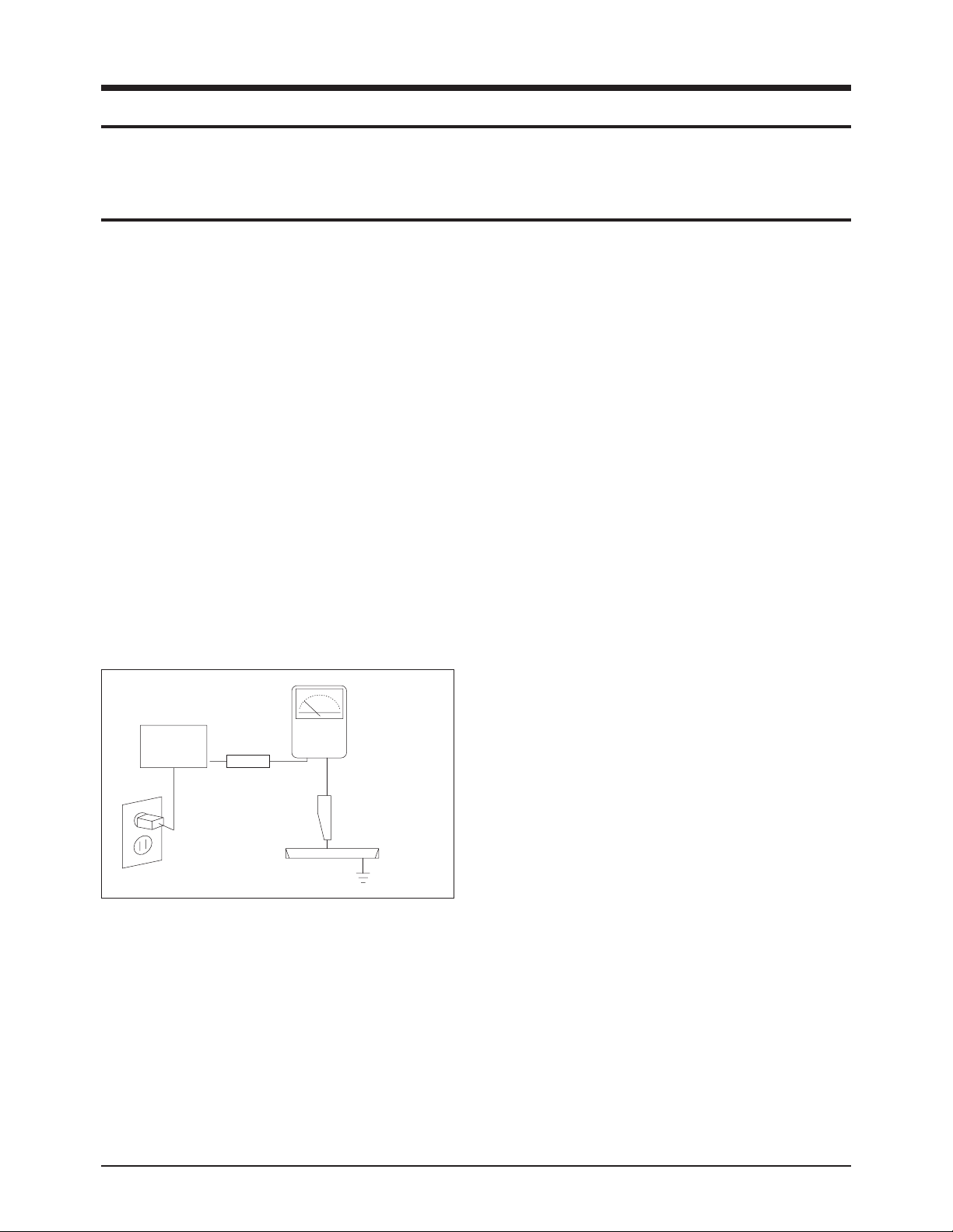
3. Check for Electricity Leakage (Figure 1-1)
Warning: Do not use an insulated transformer for checking the leakage. Use only those current leakage testers
or mirroring systems that comply with ANSIC 101.1 and
the Underwriter Laboratory's specifications (UL1410,
59.7).
Fig. 1-1 AC Leakage Test
4. A high voltage is maintained within the specified limits
using safety parts, calibration and tolerances. When
voltage exceeds the specified limits, check each special
part.
5. Warning for Engineering Changes:
Never make any changes or additions to the circuit
design or the internal part for this product.
Ex: Do not add any audio or video accessory
connectors. This might cause physical damage.
Furthermore, any changes or additions to the original
design/engineering will invalidate the warranty.
6. Warning - Hot Chassis:
Some TV chassis are directly connected to one end of
the AC power cord for electrical reasons.
Without insulated transformers, the product can only be
repaired safely when the chassis is connected to the
earthed end of the AC power source.
To make sure the AC power cord is properly connected,
follow the instructions below. Use the voltmeter to
measure the voltage between the chassis and the
earthed ground. If the measurement is over 1.0V, unplug
the AC power cord and change the polarity before reinserting it. Measure the voltage between the chassis
and the ground again.
7. Some TV chassis are shipped with an additional
secondary grounding system. The secondary system is
adjacent to the AC power line. These two grounding
systems are separated in the circuit using an
unbreakable/unchangeable insulation material.
8. When any parts, material or wiring appear overheated or
damaged, replace them with new regular ones
immediately. When any damage or overheating is
detected, correct this immediately and make a regular
check of possible errors.
9. Check for the original shape of the lead, especially that
of the antenna wiring, any sharp edges, the AC power
and the high voltage power. Carefully check if the wiring
is too tight, incorrectly placed or loose. Never change the
space between the part and the printed circuit board.
Check the AC power cord for possible damages. Keep
the part or the lead away from any heat-emitting
materials.
Precaution
Samsung Electronics 1-1
To avoid possible damages or electric shocks or exposure to radiation, follow the instructions below with regard to safety,
installation, service and ESD.
1. Precaution
1-1 Safety Precautions
(READING SHOULD
DEVICE
UNDER
TEST
EXPOSED METAL
2-WIRE CORD
ALSO TEST WITH
PLUG REVERSED
(USING AC ADAPTER
PLUG AS REQUIRED)
TEST ALL
SURFACES
LEAKAGE
CURRENT
TESTER
NOT BE ABOVE
0.5mA)
EARTH
GROUND

10. Safety Indication:
Some electrical circuits or device related materials
require special attention to their safety features, which
cannot be viewed by the naked eye. If an original part is
replaced with another irregular one, the safety or
protective features will be lost even if the new one has a
higher voltage or more watts.
Critical safety parts should be bracketed with ( ).
Use only regular parts for replacements (in particular,
flame resistance and dielectric strength specifications).
Irregular parts or materials may cause electric shock or
fire.
Precaution
1-2 Samsung Electronics
!

1. The service instructions are printed on the cabinet, and
should be followed by any service personnel.
2. Make sure to unplug the AC power cord from the power
source before starting any repairs.
(a) Remove or re-install parts or assemblies.
(b) Disconnect the electric plug or connector, if any.
(c) Connect the test part in parallel with the electrolytic
capacitor.
3. Some parts are placed at a higher position than the
printed board. Insulated tubes or tapes are used for this
purpose. The internal wiring is clamped using buckles to
avoid contact with heat emitting parts. These parts are
installed back to their original position.
4. After the repair, make sure to check if the screws, parts
or cables are properly installed. Make sure no damage is
caused to the repaired part and its surroundings.
5. Check for insulation between the blade of the AC plug
and that of any conductive materials (i.e. the metal
panel, input terminal, earphone jack, etc).
6. Insulation Check Process: Unplug the power cord from
the AC source and turn the switch on. Connect the insulating resistance meter (500v) to the AC plug blade.
The insulating resistance between the blade of the AC
plug and that of the conductive material should be more
than 1 ㏁.
7. Any B+ interlock should not be damaged.
If the metal heat sink is not properly installed, no
connection to the AC power should be made.
8. Make sure the grounding lead of the tester is connected
to the chassis ground before connecting to the positive
lead. The ground lead of the tester should be removed
last.
9. Beware of risks of any current leakage coming into
contact with the high-capacity capacitor.
10. The sharp edges of the metal material may cause
physical damage, so ensure wearing protective gloves
during the repair.
Precaution
Samsung Electronics 1-3
Warning 1: First carefully read the "Safety Instruction" in this service manual.
When there is a conflict between the service and the safety instructions, follow the safety instruction at all times.
Warning 2: Any electrolytic capacitor with the wrong polarity will explode.
1-2 Servicing Precautions

1-3 Static Electricity Precautions
1. Some semi-conductive ("solid state") devices are
vulnerable to static electricity. These devices are known
as ESD. ESD includes the integrated circuit and the field
effect transistor. To avoid any materials damage from
electrostatic shock, follow the instructions described
below.
2. Remove any static electricity from your body by
connecting the earth ground before handling any
semi-conductive parts or ass'ys. Alternatively, wear a
dischargeable wrist-belt.
(Make sure to remove any static electricity before
connecting the power source - this is a safety instruction
for avoiding electric shock)
3. Remove the ESD ass'y and place it on a conductive
surface such as aluminum foil to prevent accumulating
static electricity.
4. Do not use any Freon-based chemicals.
Such chemicals will generate static electricity that
causes damage to the ESD.
5. Use only grounded-tip irons for soldering purposes.
6. Use only anti-static solder removal devices.
Most solder removal devices do not support an
anti-static feature. A solder removal device without an
anti-static feature can store enough static electricity to
cause damage to the ESD.
7. Do not remove the ESD from the protective box until the
replacement is ready. Most ESD replacements are
covered with lead, which will cause a short to the entire
unit due to the conductive foam, aluminum foil or other
conductive materials.
8. Remove the protective material from the ESD
replacement lead immediately after connecting it to the
chassis or circuit ass'y.
9. Take extreme caution in handling any uncovered ESD
replacements. Actions such as brushing clothes or lifting
your leg from the carpet floor can generate enough static
electricity to damage the ESD.
Precaution
1-4 Samsung Electronics
CAUTION
These servicing instructions are for use by
qualified service personnel only.
To reduce the risk of electric shock do not
perform any servicing other than that contained in the
operating instructions unless you are qualified to do so.

Precaution
Samsung Electronics 1-5
1-4 Installation Precautions
1. For safety reasons, more than two people are required
for carrying the product.
2. Keep the power cord away from any heat emitting
devices, as a melted covering may cause fire or electric
shock.
3. Do not place the product in areas with poor ventilation
such as a bookshelf or closet. The increased internal
temperature may cause fire.
4. Bend the external antenna cable when connecting it to
the product. This is a measure to protect it from being
exposed to moisture. Otherwise, it may cause a fire or
electric shock.
5. Make sure to turn the power off and unplug the power
cord from the outlet before repositioning the product.
Also check the antenna cable or the external connectors
if they are fully unplugged. Damage to the cord may
cause fire or electric shock.
6. Keep the antenna far away from any high-voltage cables
and install it firmly. Contact with the high-voltage cable or
the antenna falling over may cause fire or electric shock.
7. Check the basics of the screen test.
- Image position/size, Tilt adjustment

1-6 Samsung Electronics
MEMO

Product Specification
Samsung Electronics 2-1
2. Product Specification
2-1 Product Features
Block Specfication Core Parts Remark
CRT 29" FLATAK CRT GREEN CRT
RF Part 1TUNER F/S TUNER TDQ-6F/13F2S
Power
WORLD WIDE INPUT VOLTAGE RANGE
STD-BY : 5W UNDER
STR-W6750F
Video
- MULTI SYSTEM(NT/PAL)
- 1H Comb Filter
TDA12005PQ,
TDA12015PQ
Audio
- Output : 5W/10W/15W X2
- BTSC/SAP STEREO : PSEUDO STEREO, TURBO PLUS
TDA12005PQ,
TDA12015PQ,
TDA7297SA
Cabinet - 29" CABINET
Other
- BASIC MODEL : CL29M21FQ2XXAX
- UOC3 with a built-in MSP
- TURBO → TURBO PLUS
■ Core Parts Functions
- TDA12005PQ : Video/Sound Processing and MICOM (NTSC)
- TDA12015PQ : Tri-noma
- STR-W6750F : SMPS Power STR
- TDA7297SA(or 7266) : 5W ~ 15W Sound Output BTLAMP
- 24C16 : 16K EEPROM
- LA78040 : Vertical Deflection AMP
- C5936 : H-OUT S/W TR
- TDA-6F/13F2S : F/S PALTuner
- TDA6108AJF : R/G/B Drive AMPIC
Product Specification
2-2 Samsung Electronics
2-2 Key Features
Model CL29K5MQ
Voltage AC100-240V
Frequency of Operation 50/60 Hz
Power Consumption 110 Watts
Dimensions (mm/inches)
766 X 558 X 586/
30.16 X 21.97 X 23.07
Weight (Kg/ lbs) 41/90.39
■ Hardware Configuration
- 1 Chip : UOC3 TDA12005PQ(CHROMA, IF+Deflection, MICOM, MSP)
- Tuner : TDA-6F/13F2S
- SOUND AMP: TDA7297SA(ZIP, 15P, -, DUAL, 32dB, PLASTIC, 20V, 30W)
- SMPS Controller : STR-W6750F(6P, TO-3P-F7L)
- Vertical AMP : LA78045(TO220, 7P, 15V)
- Flyback Trans : FOK14B001(11P, 27KV)
- CRT : A51QDX993X(A) (AK, 1H Single Focus)
■ Software Configuration
- MCU : 80C51-controller core
- Data Capture for US Closed Caption
- 0.4883s machine cycle
■ Picture
- Enhance : DNIe Jr.(Digital Natural Image Engine)
- System : NTSC3.58
- Interlaced(60Hz)
- AKB(Auto Kinetic Bais)
- Comb Filter : 1H Comb Filter
- 4:3/Zoom
■ Sound
- BTSC/SAP-STEREO
- Output : 5/10/15W X 2CH
- Auto Stereo, Sound Equalizer, Auto Mute, Auto Volume Limit, PSEUDO STEREO, TURBO PLUS
■ Feature
- Composite (RCAA/V, DVD), S-Video(Y/C)
- Picture Size : Zoom/4:3
- Auto Serch
- Sleep Timer : 180 Min
- Clock Setting
- Blue Screen, Melody On-Off, Picture Mode Select
■ In/Out Terminals
- Rear : 2RCA/DVD/S-VHS
- Front or Side A/V Input(Side A/V Preferability)
■ Remocon
- Universal Interface TM75
■ Power Consumption : 105W
Product Specification
Samsung Electronics 2-3
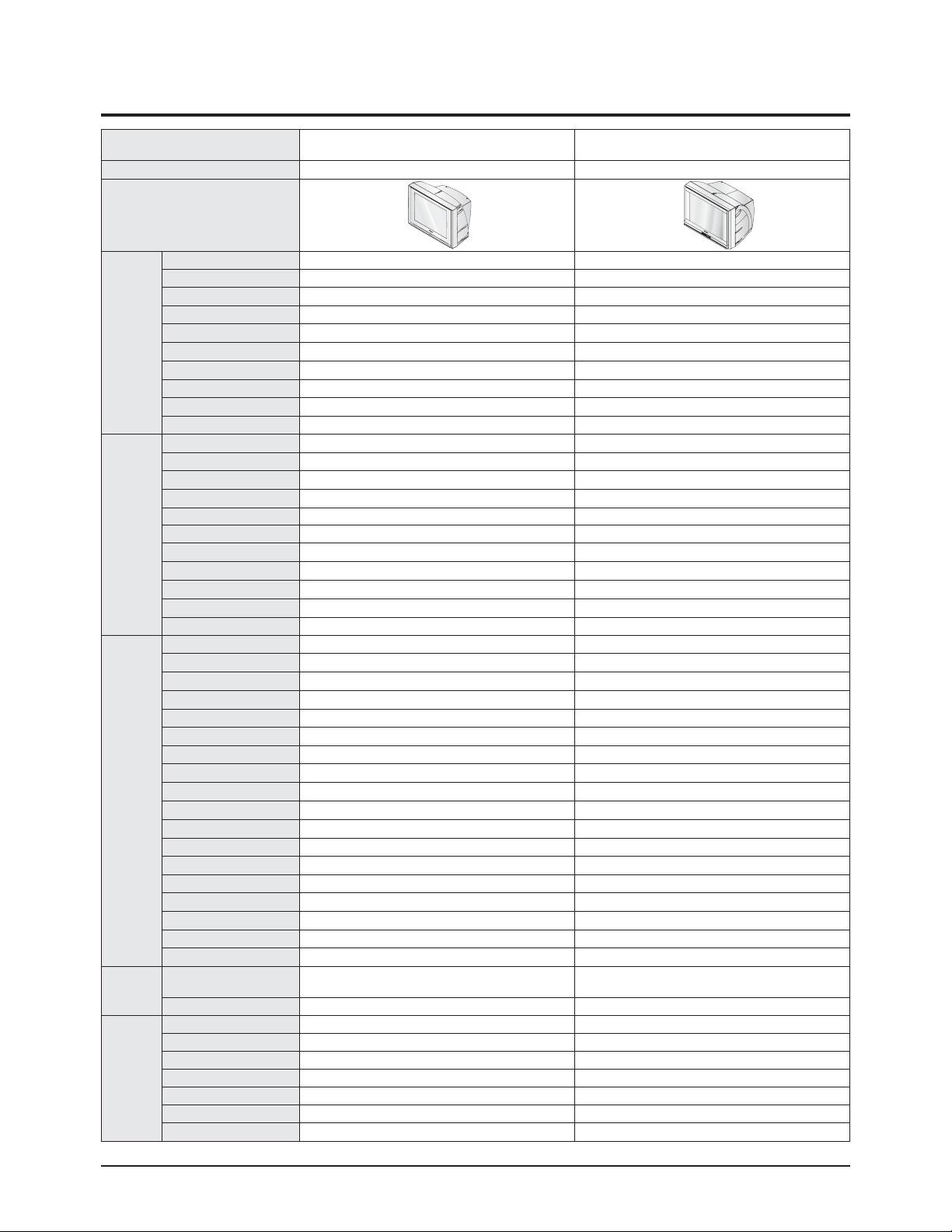
2-3 Specifications Analysis
Model CL29M21PQ CL29K5MQ
Chassis KS7A K16A
Design
Picture
Screen Size 29" 29"
Pure Flat CRT
○ ○
DNIe Jr.
○ ○
Comb Filter 1H 1H
Velocity Modulation
× ×
Video Noise Reduction
○ ○
Auto Kinetic Bias
○ ○
Color Tone Control
○ ○
Tilt Control
× ×
Picture Mode 4 Mode 4 Mode
Sound
MTS/SAP
○ ○
Output Power(RMS) 15W x 2 15W x 2
Tweeter
× ×
BBE
× ×
Surround Surround Surround
Sound Mode 5 Mode 5 Mode
Graphic Equalizer
× ×
Sub-Woofer Speaker
× ×
Auto Volume Leveler
○ ○
Melody On/Off
○ ○
Turbo Sound
○ ○
Convenience
PIP 2T (Optional)
×
Plug & Play
○ ○
Zoom Mode
○ ○
OSD Demo
○ ○
OSD Language E/F/S E/F/S
Previous Channel
○ ○
Closed Caption
○ ○
On/Off Timer
○ ○
Sleep Timer
○ ○
Auto Power Off
○ ○
Clock
○ ○
Channel Scan
× ×
Self-diagnostic System
○ ○
Remote Control TM76 TM75
Remote Surf
○ ○
Channel Labelling
○ ○
Blue Screen
○ ○
Rack
× ×
Voltage
Voltage
AC100-240V
AC120V (Mexico)
AC100-240V
Stand-by under 3W under 5W
Jacks
RF Input R1 R1
A/V Input S1/R2 S1/R2
Monitor Output R1 R1
S-VHS Input R1 R1
Headphone S1 S1
DVD Input
○ ○
PC Input(VGA)
× ×

Product Specification
2-4 Samsung Electronics
2-4 Accessories
Accessories Item Item code Remark
SuppliedAccessories
Remote Control
AAAAlkaline Battery (2)
AA59-00316B
4301-000121
Samsung Service center
Owner's Instructions AA68-03671H
Warranty Card BN68-00797A
Accessories that can be purchased
additionally
Video Cable /
Audio Cable
-
Internal shopping mallAntenna Cable -
Component Cable -

Alignment & Adjustment
Samsung Electronics 3-1
3. Alignment & Adjustment
3-1 Service Instruction
1. General Adjustment :
In general, a color TV can provide ideal visual quality by adjusting the basic settings such as the vertical size, horizontal size,
focus, etc.
Display a black and white picture on the screen to check if the picture is clearly displayed.
If there are some 'spotted' points on the screen when displaying a black and white picture, degauss the screen using the
degauss coil. If the spotted points remain, re-adjust the purity and the convergence.
This completes the basic performance examination.
Notice.
■ These adjustments and the check list are only applied to K16A chassis-applied models.
■ Only use 230V for the measurement set. It is recommended using an insulation transformer when supplying power to
the set so as to prevent shock to the set or to yourself.
■ These adjustment specifications have been created on the basis of the domestic K16A chassis-applied remote control
model. Some of the contents may be changed subject to the sales location and the product specifications.
※When replacing the Module Service Instruction
1. When replacing the MAIN Board : Tilt adjustment, Focus adjustment, Screen voltage, W/B adjustment are all required. Since
the settings including the Channel information, Deflection, etc. are saved to the EEPROM,
recogfigure these settings when replacing the MAIN Board.
The notation of the software information : T-RHMNSA-1000 refer to "GREEN2 BASIC MODEL EUROPE. ver.1000"
Since the settings including the Channel information, Deflection, etc. are
saved to the EEPROM, recogfigure these settings when replacing the MAIN Board.
2. When replacing the CRT Ass'y : No adjustments required
3. When replacing the front panel Master Power switch : No adjustments required
4. When replacing the Side AV Ass'y : No adjustments required
5. When replacing the PIP Module : No adjustments required
6. When replacing the Control Ass'y : No adjustments required
7. When replacing the PFC Ass'y : No adjustments required

1. To enter Service Mode, press the keys on the remote control according to the following sequence. (in Stand-by status)
Mute → 1 → 8 → 2 → Power On
※ When failing to enter Service Mode, repeat the procedure above.
2. The initial screen of Service Mode.
3. Functions of the Keys within Service Mode.
Alignment & Adjustment
3-2 Samsung Electronics
3-2 How to Access Service Mode
MENU Show all menus
▲ / ▼
Move the cursor to select an item.
◀ / ▶
Adjust the selected configuration value
Option1 XX XX XX XX XX
Option2
Deflection
Video Adjust1
Video Adjust2
Video Adjust3
Video Adjust4
Video Adjust5
YC Delay
Others
Bus Stop Off
CHECKSUM 0000
G2 Adjust
RESET
T-RHMNSA-XXXX 20XX/XX/XX

Alignment & Adjustment
Samsung Electronics 3-3
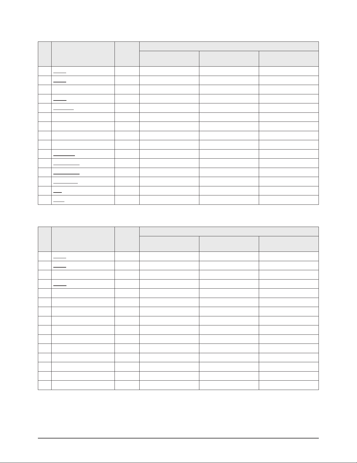
3-3 Factory Data
1. Option1
2. Option2
★ The underlined are items applied during the service adjustment. None of the others should be adjusted.
No Item Var./Fixed
Model
CL29M16MQ CL29M2MQ
CL29M21FQ
CL29T21FQ
1 System Var. CL CL CL
2 Video Mute Var. 400msec 400msec 400msec
3 A
V Jack
Var. 2RCA+S+DVD 2RCA+S+DVD 2RCA+S+DVD
4 Sound Var. Stereo Stereo Stereo
5 Volume Curve Var. Large Large Large
6 Initial Lang. Var. Engilsh Engilsh Engilsh
7 T
ilt
Var. Off Off On
8 DNIe Jr Var. Off On On
9 PIP Var. Off Off 2-Tuner
10 Auto Power On Var. Off Off Off
11 Caption Var. On On On
12 Vchip Var. Off Off Off
13 Child Look Va r. Off Off Off
14 Plug Play Var. On On On
15 StandBy LED Var. Off Off Off
No Item Var./Fixed
Model
CL29M16MQ CL29M2MQ
CL29M21FQ
CL29T21FQ
1 X-Ray Protect Var. Off Off Off
2 High Deviation Var. Off Off Off
3 V-Guard Var. On On On
4 ACS Var. Off Off Off
5 CRT Var. 4:3 Zoom 4:3 Zoom 4:3 Zoom
6 LNA Va r. Off Off On
7 Hotel Mode Var. Off Off Off
8 Philippines Var. Off Off Off
Alignment & Adjustment
3-4 Samsung Electronics
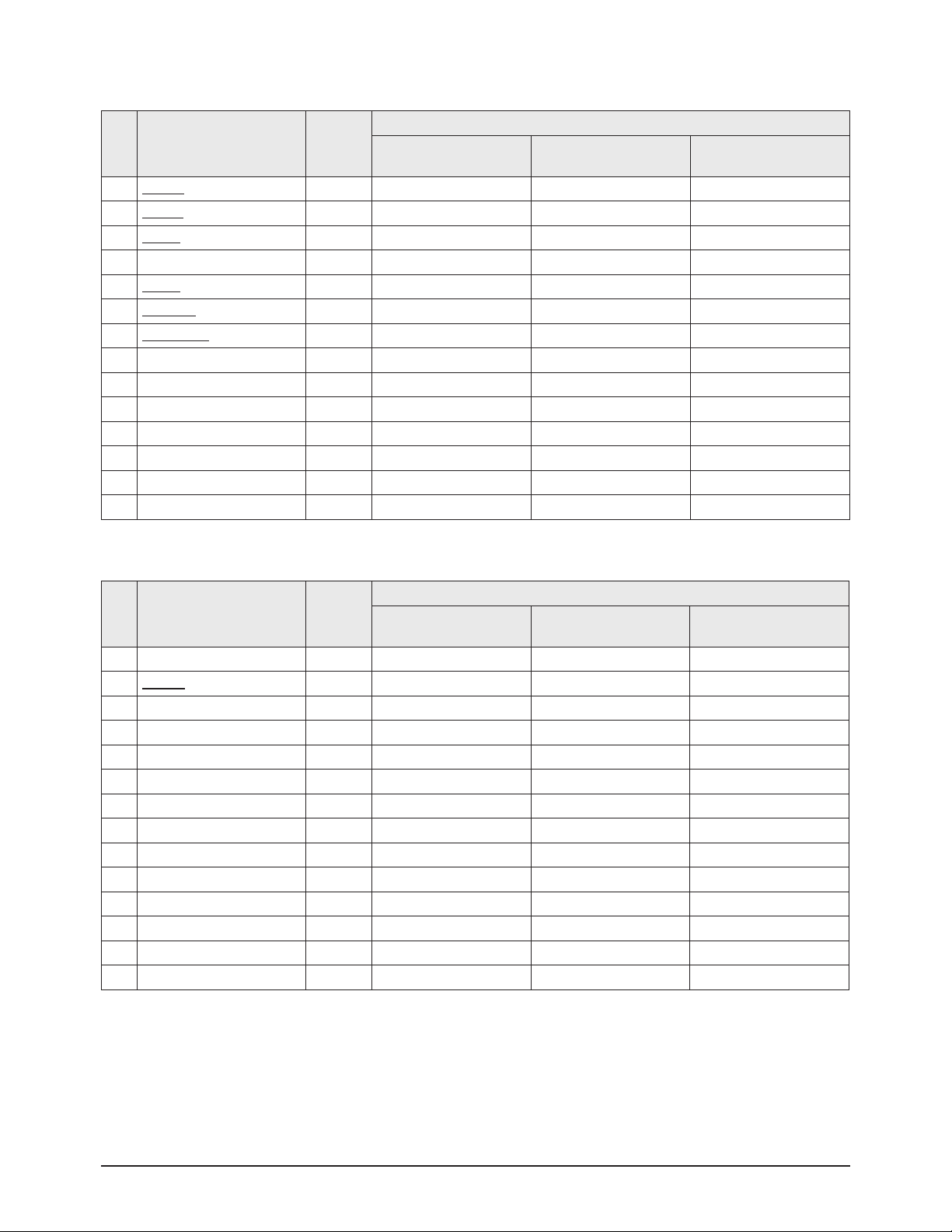
3. Deflection(NTSC 60Hz)
4. Deflection(PAL N 50Hz)
No Item Var./Fixed
Model
CL29M16MQ CL29M2MQ
CL29M21FQ
CL29T21FQ
1 V Amp Var. 47 47 47
2 V Shift Var. 24 24 24
3 H EW Var. 48 48 48
4 H Shift Var. 49 49 49
5 V Linearity Var. 30 30 30
6 V S-Correction Fixed 32 32 32
7 V Slope Fixed 30 30 30
8 V Scroll Fixed 25 25 25
9 V Zoom Fixed 48 48 48
10 H Parabola Var. 45 45 45
11 Upper Corner Var. 51 51 51
12 Lower Corner Var. 54 54 54
13 H Trapezium Va r. 22 22 22
14 Bow Var. 26 26 26
15 Angle Var. 29 29 29
No Item Var./Fixed
Model
CL29M16MQ CL29M2MQ
CL29M21FQ
CL29T21FQ
1 V
Amp
Var. 0 0 0
2 V Shift Var. 0 0 0
3 H EW Var. 0 0 0
4 H Shift Var. -6 -6 -6
5 V Linearity Fixed 0 0 0
6 V S-Correction Fixed 0 0 0
7 V Slope Fixed 0 0 0
8 V Scroll Fixed 0 0 0
9 V Zoom Fixed 0 0 0
10 H Parabola Fixed 0 0 0
11 Upper Corner Fixed 0 0 0
12 Lower Corner Fixed 0 0 0
13 H Trapezium Fixed 0 0 0
14 Bow Fixed 0 0 0
15 Angle Fixed 0 0 0

Alignment & Adjustment
Samsung Electronics 3-5
Alignment & Adjustment
3-6 Samsung Electronics
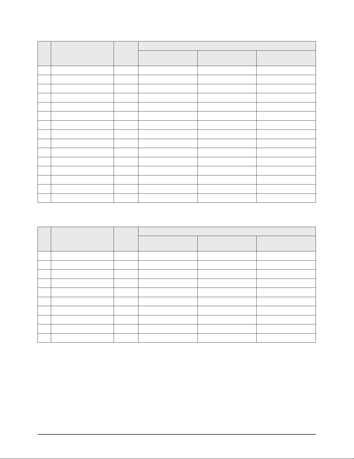
5. Video Adjust1
6. Video Adjust2
No Item Var./Fixed
Model
CL29M16MQ CL29M2MQ
CL29M21FQ
CL29T21FQ
1 R Cutoff Var. 20 20 20
2 B Cutof
f
Var. 49 49 49
3 R Drive Va r. 29 29 29
4 G Drive Fixed 15 15 15
5 B Drive Var. 21 21 21
6 Sub Bright Va r. 17 17 17
7 Sub Contrast Var. 7 7 7
8 PAL/SECAM Sub Color Fixed 23 23 23
9 NTSC Sub Color Fixed 21 21 21
10 NTSC Sub Tint Fixed 15 15 15
11 YUV Sub Tint Fixed 32 32 32
12 AKB Option Fixed 0 0 0
13 Peaking CFO & Delay Mode Fixed 1 1 1
14 Sub Sharpness-RF Fixed 10 10 10
No Item Var./Fixed
Model
CL29M16MQ CL29M2MQ
CL29M21FQ
CL29T21FQ
1 Melody Volume Fixed 25 25 25
2 RF AGC Var. 24 24 24
3 IF AGC Speed Fixed 1 1 1
4 VM Mode Fixed 0 0 0
5 VM Gain Fixed 0 0 0
6 VM Delay Fixed 0 0 0
7 Blue Stretch Fixed 0 0 0
8 G2 Adjust Bright Fixed 48 48 48
9 Soft Clipping Level Fixed 1 1 1
10 Peak White Limit Fixed 8 8 8
11 Cathode Drive Level Fixed 4 4 4
12 IF Demodulator Fixed 30 30 30
13 Fast Filter IF PLL Fixed 0 0 0
14 FOAB Fixed 3 3 3
Alignment & Adjustment
Samsung Electronics 3-7
7. Video Adjust3
8. Video Adjust4
No Item Var./Fixed
Model
CL29M16MQ CL29M2MQ
CL29M21FQ
CL29T21FQ
1 PIP Contrast Fixed 10 10 10
2 PIP Bright Fixed 4 4 4
3 PIP Tint Fixed 3 3 3
4 PIP Color Fixed 8 8 8
5 PIP YC Delay Fixed 12 12 12
6 PIP PAL V.Pos Fixed 1 1 1
7 PIP NTSC V. Pos Fixed 1 1 1
8 PIP H. Pos Fixed 2 2 2
9 PIP R Cutoff Fixed 7 7 7
10 PIP G Cutoff Fixed 6 6 6
11 PIP B Cutoff Fixed 7 7 7
12 PIP R Drive Fixed 139 139 139
13 PIP G Drive Fixed 152 152 152
14 PIP B Drive Fixed 142 142 142
15 PIP AGC Mode Fixed 3 3 3
No Item Var./Fixed
Model
CL29M16MQ CL29M2MQ
CL29M21FQ
CL29T21FQ
1 IF Preset Value 1 Fixed 32 32 32
2 IF Preset Value 2 Fixed 32 32 32
3 IF PLL Osc Preset Value Fixed 0 0 0
4 Preset Gain R Fixed 20 20 20
5 Preset Gain G Fixed 20 20 20
6 Preset Gain B Fixed 20 20 20
7 Turbo Center Frequency Fixed 0 0 0
8 DCXO Caps/NICAM Center Fixed 59 59 59
9 DCXO Scaning Control Gain Fixed 3 3 3
10 Component H-Shift Offset Fixed -4 -4 -4
Alignment & Adjustment
3-8 Samsung Electronics
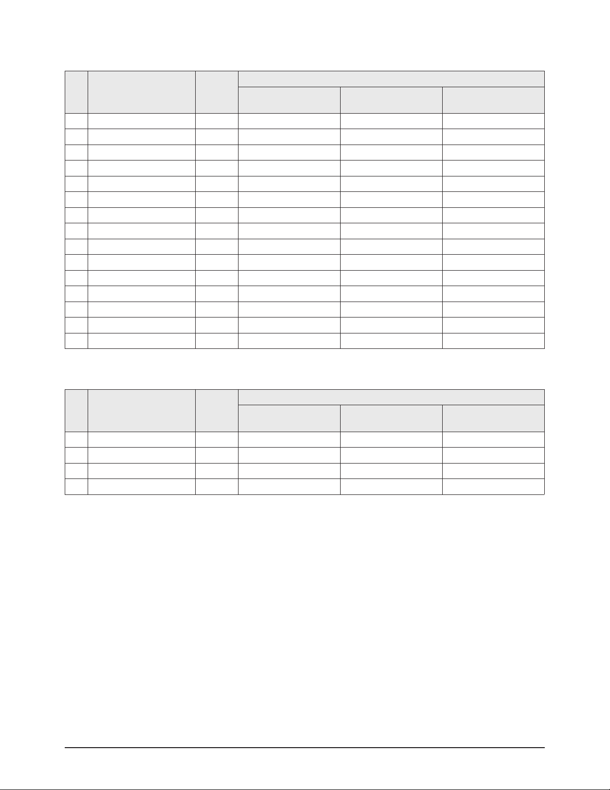
10. YC Delay
9. Video Adjust5
No Item Var./Fixed
Model
CL29M16MQ CL29M2MQ
CL29M21FQ
CL29T21FQ
1 System I Output Signal AMP Fixed 0 0 0
2 Bypass of Chroma Base Band Fixed 1 1 1
3 Fixed Beam Current Fixed 0 0 0
4 Fixed Beam Current 1 Fixed 0 0 0
5 IF Sensitivity Fixed 0 0 0
6 Forced Digital Interface Fixed 0 0 0
7 Enable Digital Interface Fixed 0 0 0
8 Sync Performance Trick Mode Fixed 0 0 0
9 Vertical Overscan Fixed 0 0 0
10 Beam Current Limiting Fixed 0 0 0
11 Comb filter Fixed 0 0 0
12 De Interlace Fixed 0 0 0
13 Chroma Trap Mode Fixed 0 0 0
14 Black Current Measure Line Fixed 0 0 0
15 EHT Tracking Mode Fixed 1 1 1
No Item Var./Fixed
Model
CL29M16MQ CL29M2MQ
CL29M21FQ
CL29T21FQ
1 PAL Delay Fixed 8 8 8
2 NTSC Delay Fixed 8 8 8
3 PALAV Delay Fixed 8 8 8
4 NTSC AV Delay Fixed 8 8 8

Alignment & Adjustment
Samsung Electronics 3-9
11. Others
12. Bus Stop : Off
13. Checksum : 0000
14. G2 Adjust : Screen Adjust OK/NG/Obove
15. Reset
No Item Var./Fixed
Model
CL29M16MQ CL29M2MQ
CL29M21FQ
CL29T21FQ
1 Service Blanking Fixed 0 0 0
2 High Current Level Fixed 1 1 1
3 Black Area Fixed 2 2 2
4 Black Stretch Fixed 2 2 2
5 OSD Brightness Fixed 10 10 10
6 PWL Active Fixed 1 1 1
7 Bypass Peaking Delay Fixed 0 0 0
8 Ratio Pre. & After Shoot Fixed 2 2 2
9 Ratio Posi. & Nega Peaks Fixed 1 1 1
10 Dynamic Skin Fixed 0 0 0
11 Gamma & White Stretch Fixed 1 1 1
12 Video Depandent Coring Fixed 2 2 2
13 PAL/NTSC Ident Sensitivity Fixed 1 1 1
14 Comb Filter Diode Clamp Fixed 1 1 1
15 DC Transfer Ratio Fixed 1 1 1
Item DATA
MICOM(UOC3)
Version NO.
T-RHMNSA-****
2005/**/**
T-RHMNSA-****
2005/**/**
T-RHMNSA-****
2005/**/**
White Balance
(NTSC/PAL N-M)
275/275/40ft
265/265/2.0ft
275/275/40ft
265/265/2.0ft
275/275/40ft
265/265/2.0ft

Alignment & Adjustment
3-10 Samsung Electronics
3-4 Service Adjustment
3-4-1 Adjusting the Picture Size
■ Since the K16A chassis includes a deflection adjustment of the Factory Data, adjustments must be performed according to the
following procedures when replacing the Main Board.
1. Display the Lion pattern.
2. Press "Power Off → Mute → 1 → 8 → 2 → Power On"
using the remote control and enter Factory Mode.
3. Enter Deflection Mode. 4. Adjust the V-AMP, V-SHIFT, H-AMP and H-SHIFT items so
that the width becomes 5 and the height becomes 4.
Alignment & Adjustment
Samsung Electronics 3-11
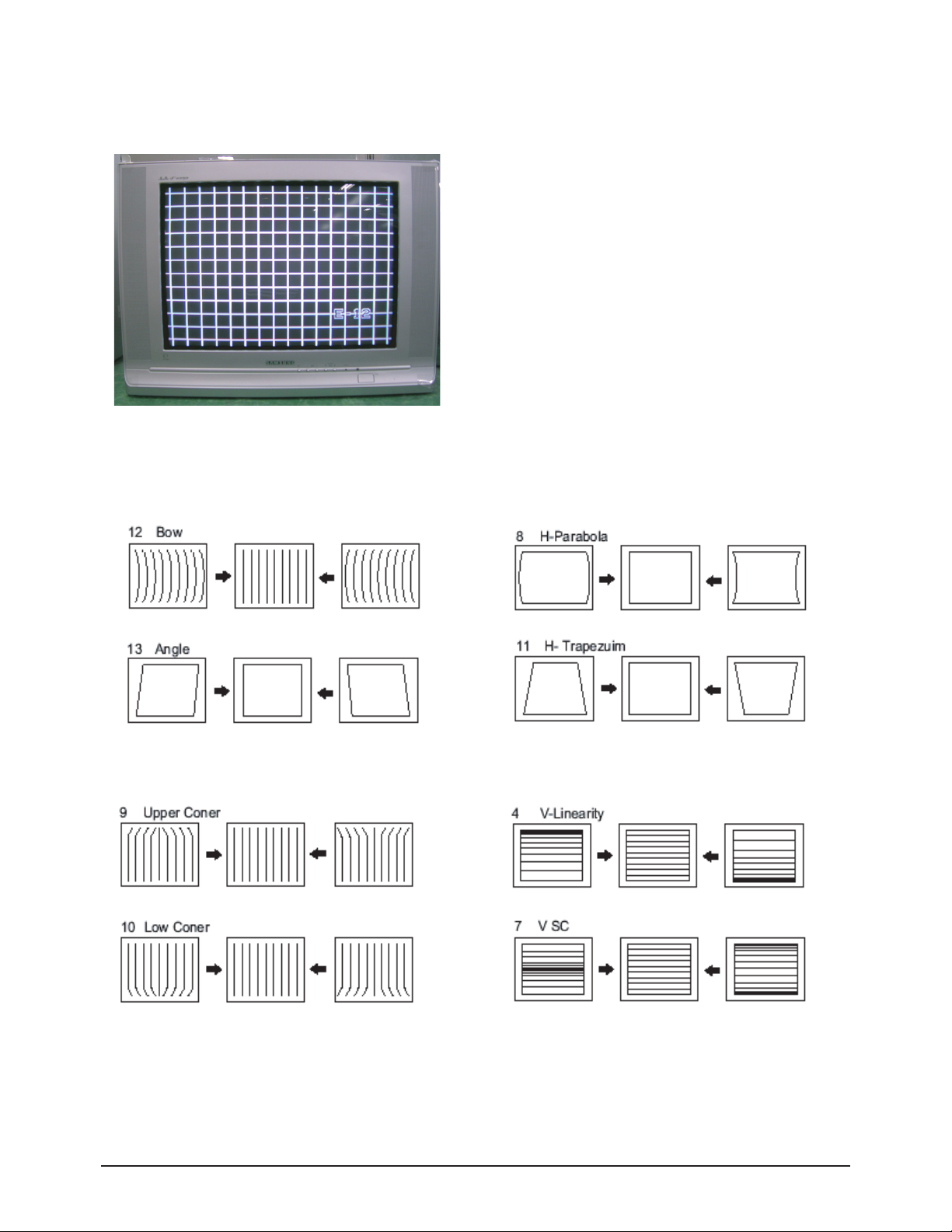
3-4-2 Adjusting the Picture Straight Lines
1. Display the Cross Hatch pattern.
2. Adjust settings other than V-AMP, V-SHIFT, H-AMP and H-SHIFT so that straight lines are displayed without curves.
7. When the adjustments are complete, display the Lion pattern and check that the picture size has not been changed.
If there is no change, finish the adjustments.
3. Adjust BOW and the Angle settings so that the center line
becomes a straight line.
4. Adjust the H-Parabola and H-Trapezium settings so that
the left and right lines become straight.
5. Adjust the Upper Corner and the Low Corner settings so that
the end of the lines become straight.
6. Adjust the V-Linearity and V-SC settings so that the
intervals of the horizontal lines become uniform.
 Loading...