

SAMSUNG CL29K40MQ2XXAP Service Manual

COLOR TELEVISION RECEIVER
Chassis : K16A(N)_Ray
Model : CL29K40MQ2XXAP
COLOR TELEVISION RECEIVER FEATURES
■■
Turbo Plus
■
DNIe jr.
■■
Low Stand-By Power Wattage
■
SOUND Equalizer
SERVICE
Manual
CL-29K40MQ

Wiring Diagram
Samsung Electronics 8-1
8. Wiring Diagram
8-1 Overall Wiring
AV PCB
CRT SIGNAL
& POWER
PIP MODULE
SPEAKER
CONTROL PCB
POWERSWITCH

Wiring Diagram
8-2 Samsung Electronics
8-2 Pin Connection
CN901
Pin NO. Pin Nam e
1STD-LED
2TIME-LED
3GND
4VCC
5I.R
CNP01
Pin NO. Pin Nam e
1B+8V
2B+5V
3GND
4SCL
5SDA
6GND
7H-SYNC
8V-SYNC
9PIP-F/B
10 PIP- B
11 PIP- G
12 PIP- R
CN9 02
Pin NO. Pin Nam e
1KEY-IN2
2KEY-IN1
3GND
4KEY-IN3
FN01
PinNO. PinName
CNP02
Pin NO. Pin Nam e
1OSD-R
2OSD-G
3OSD-B
4OSD-F/B
5
6GND
7
8N.C
SU b-
CVBS
PIP-
CVBS
CN501A
Pin NO. Pin Nam e
1GND
2N.C
3GND
4HEATER
5N.C
6B+200V
1TILTOUT
2TILTOUT
3GND
4GND
CN5 03
Pin NO. Pin Nam e
1B-OUT
2G-OUT
3R-OUT
4GND
5SENSE
6GND
7N.C
8GND
9GND
10 N.C
11 GND
12 HEAT ER
13 N.C
14 B+ 200V
PIP MODULE
CNP01 CNP02
CN9 00
Pin NO. Pin Nam e
1SCL
2GND
3B+3.3V
4SDA
CN6 01
Pin
Pin Nam e
NO.
1R+OUT
2R-OUT
3L+OUT
4L-OUT
TU02S
CN502
Pin NO. Pin N ame
1B-OUT
2G-OUT
3R-OUT
4GND
5SENSE
6GND
7N.C
8GND
CN701
Pin NO. Pin N ame
1AV2-R-IN
2AV2-L-IN
3AV2-L-OUT
4AV2-R-OUT
5GND
6 AV2-V-IN
7GND
8 AV2-V-OUT
CN7 02
PinNO. PinName
1C-OUT
2GND
3Y-OUT
4GND
5C-IN
6GND
7Y-IN
TU01S

Troubleshooting
Samsung Electronics 6-1
6. Troubleshooting
6-1 Checkpoints by Error Mode
■ Power LED: Check that the LED works when turning the Master Switch ON/OFF
■ LED Indicators: See table 6-2-1 Basic Troubleshooting: LED Diagnosis on the Front Panel.
■ In case of a power failure or abnormal screen, check the following items.
1) Check that the power cord is correctly connected to a 230V wall outlet.
2) Check that the Master Switch has been pressed.
3) Check that the transmitter is turned on.
4) Check that transmitter device selection is set to TV.
5) Check that the signal cable is properly connected.
6) Check that channel setting has been set.
Troubleshooting
6-2 Samsung Electronics
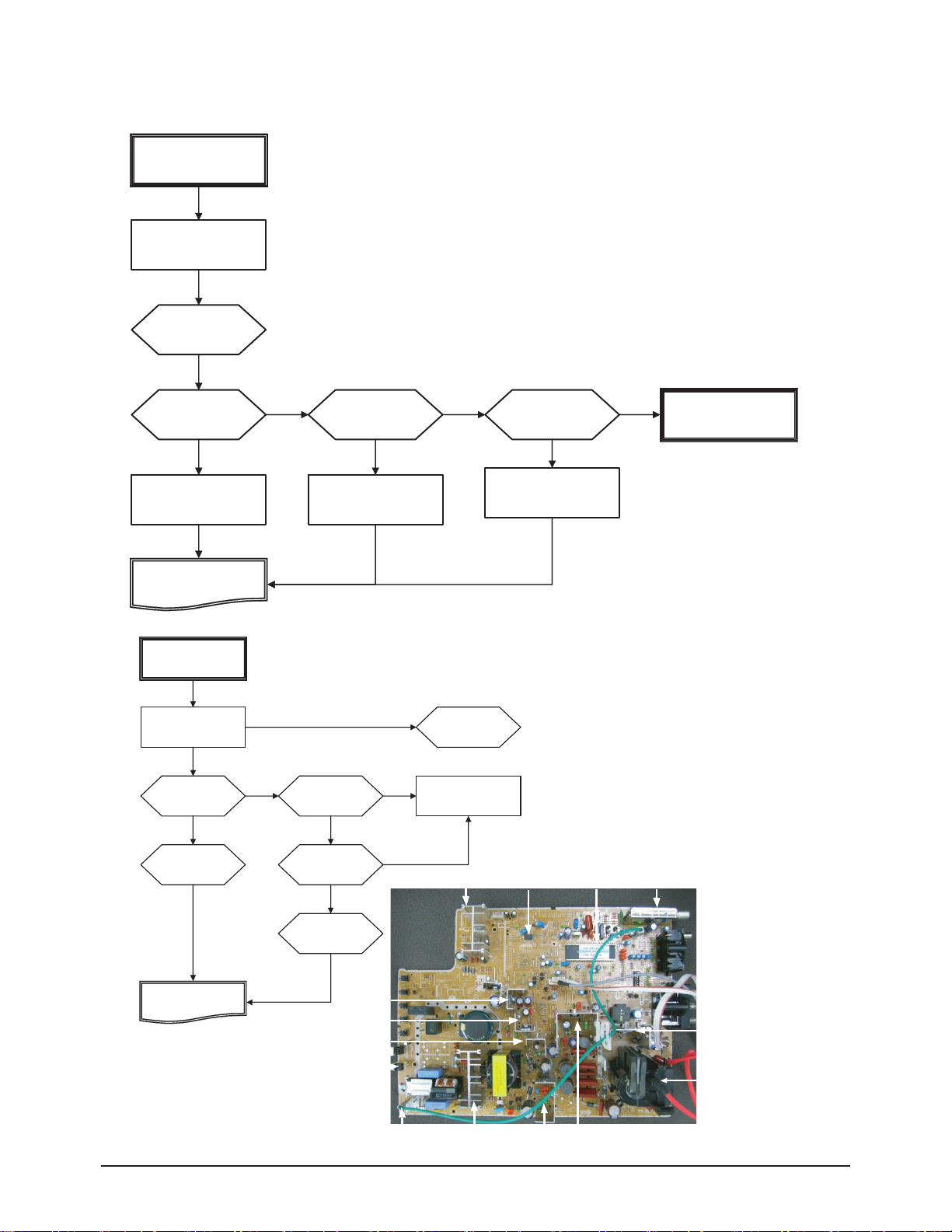
6-1-1 Flow Chart for Malfunction
dnuoS oN & erutciP oN
eht kcehC
CA
sserpmi egatlov
retsam eht kcehC
no hc
s
tiw
C
eht kceh
se
Y
Y
se
”S108PF“ ESUF
ht kcehC
ehC
eht kc
1
#”S108D“
seY
oN
e
1# S108
CI
seY
trap srehto eht kcehC
F0576W
oN
egnah
C
”S
108PF“
se
Y
egnahC
”S108
D“
”S108CI“ egnahC
taelpmoC
rewoP oN riapeR
dnuos on & erutcip oN
)KO rewop ts1(
Y
ht kcehC
oN
“
a
kcehc dn
oN
D“ eht egnahC
805A”
805A)D
(
se
enil V521+ e
seY
nepo )805AD(”118D
o
N
eht kc
ehC
seY
3# niP +B 444T
kcehc dna nepO
seY
”1
04Q“
kcehC
IC601
oN
”104Q“ eht egnahC
srehto eht kcehC
en
il +B
ht
enil V521+ e
trap srehto
IC901
IC201S
TU01S
C
taelpmo
p on riaper
rewo
IC802
IC803
IC804
LED
Power cord
IC801S
QE01
Q401S
T401S
IC301S

Troubleshooting
Samsung Electronics 6-3
6-2 Troubleshooting Procedures by Error Modes
6-2-1 Basic Troubleshooting: Diagnosis of LED on the Front Panel
6-2-2 Troubleshooting by the Checksum
■ Diagnosis of trouble by the checksum is neither reliable nor convenient.
You can only use the checksume of the current direct-view TV to determine whether the software is corrupted or not.
The Checksum value is determined according to the version of the software loaded on the set.
Therefore, you can determine whether the software has been properly downloaded, if you know the correct checksum for that
version of the software.
You can check the checksum according in the following order.
Factory Mode → Checksum → Right Button → Calculate Checksum → Output Checksum (e.g. 3036)
■ Checksum Examples
T-TR2PEU-1000 : checksum = 8036
T-TR2PEU-1010 : checksum = B612
Power Description
○
This happens when the Master Switch is not pressed or the power cord is disconnected.
●
This happens when the power cord is connected and the power switch is pressed.
If you cannot set the power switch on by pressing it, check the power switch Ass'y.
○→◑→●
If you press the power switch of the transmitter or the channel key on the remote control when in
St-BY status, the screen will be turned on.
If the LED blinks and the screen is not displayed, check the connection between the Control
Assy and the Main Board.
● : Light is On
◑ : Light is Blinking
○ : Light is Off
Troubleshooting
6-4 Samsung Electronics
6-3 Troubleshooting Procedures by ASS'Y
6-3-1 No Power (1st Power)
6-3-2 No Picture(2nd Power)
No Picture & No Sound
Check the AC
voltage impress
Check the master
switch on
Check the
FUSE “FP801S”
Yes
Change “FP801S”
Yes
Compleat
Repair No Power
Yes
No picture
(1st power OK)
Check the +125V line
No
“D811”(D811A) open
and check
Yes
Yes
Check the
“D801S” #1
No
Change “D801S”
T444 B+ Pin #3
Open and check
Yes
Check the
IC801S #1
W6750F
Change “IC801S”
Yes
Yes
No
Check the others
B+ line
Check IC501 Pin#6
Check the others part
Yes
Change IC201
No
Change the “D811”
(D811A)
Compleat
repair no picture
Check the “Q401”
Change the “Q401”
No
No
Yes
No
Change IC501

Troubleshooting
Samsung Electronics 6-5
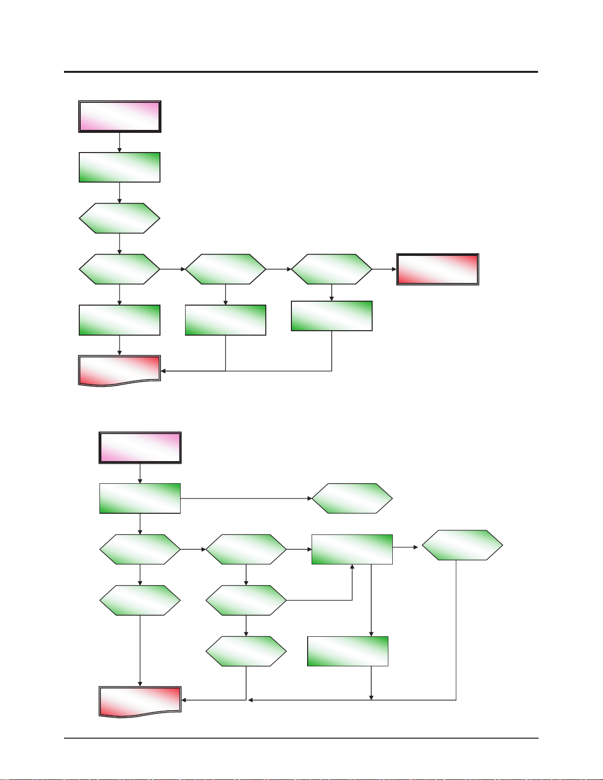
6-3-3 No Sound
No sound
(1st power OK)
Check the +14V line
No
Check FD801S
(FD802S)
No
Change FD801S
(FD802S)
Compleat
repair no sound
Yes
Check D807
No
Check IC601 Pin#6
No
Change IC601”
IC601
Yes
Check IC201 Pin#58,59
Yes
IC901
IC201S
Yes
Change IC201
TU01S
IC802
IC803
Q401S
IC804
LED
T401S
Power cord
IC801S
QE01
IC301S

6-6 Samsung Electronics
MEMO
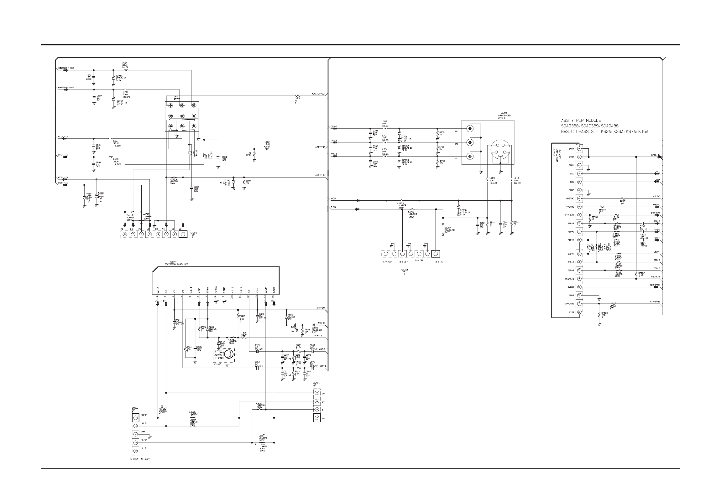
10. Schematic Diagram
Samsung Electronics
Schematic Diagram
10-1
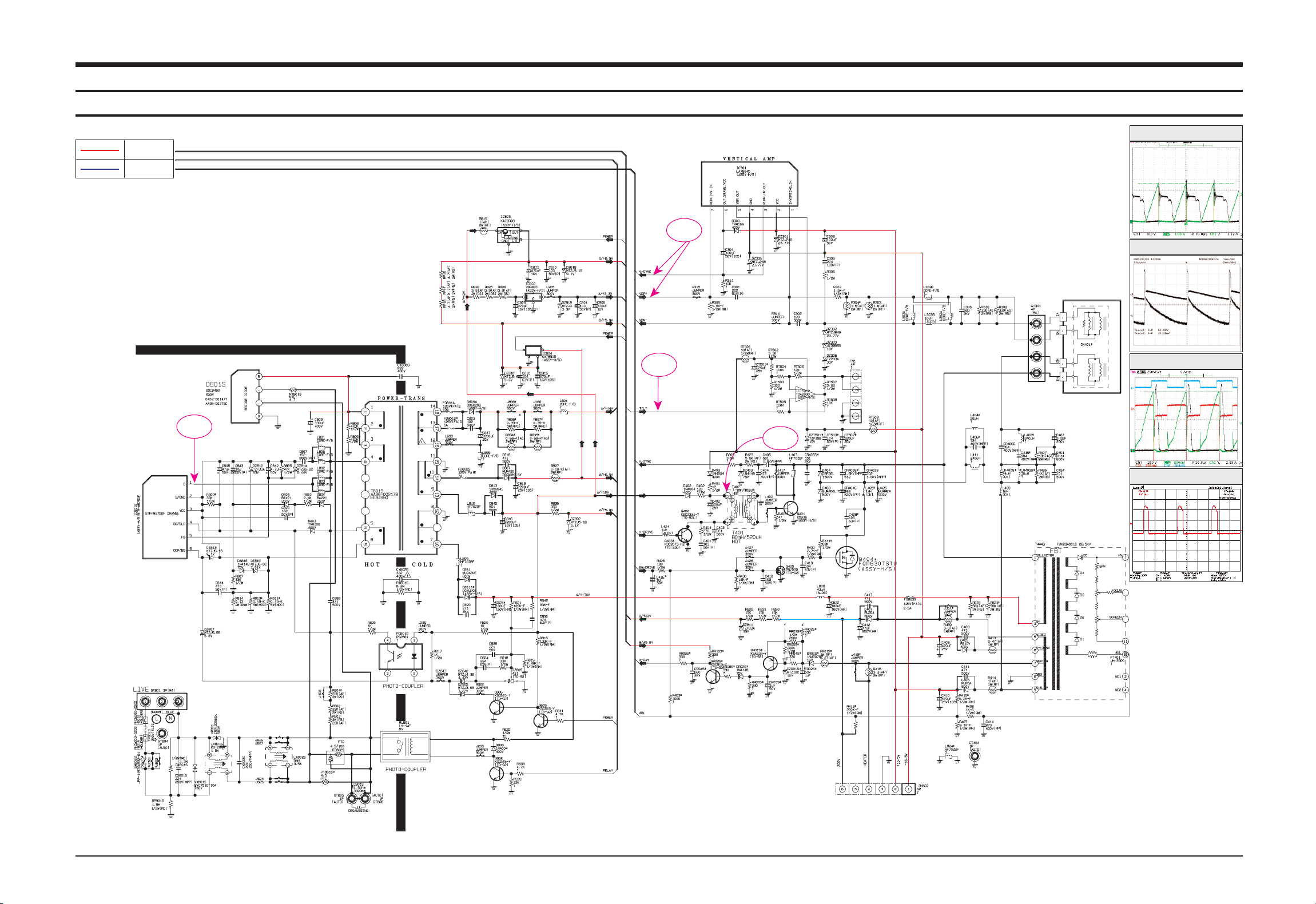
10-1 Power & Deflection Block
This Document can not be used without Samsung’s authorization.
TP01
TP02
TP03
TP08
Power
Signal
TP02
TP01
TP08
TP03

Schematic Diagram
10-2 Samsung Electronics
10-2 IF & UOC(Chroma_Micom) Block
This Document can not be used without Samsung’s authorization.
TP04
TP05
TP06
TP07
Power
Signal
TP07
TP04
TP06
TP05
Samsung Electronics
Schematic Diagram
10-3
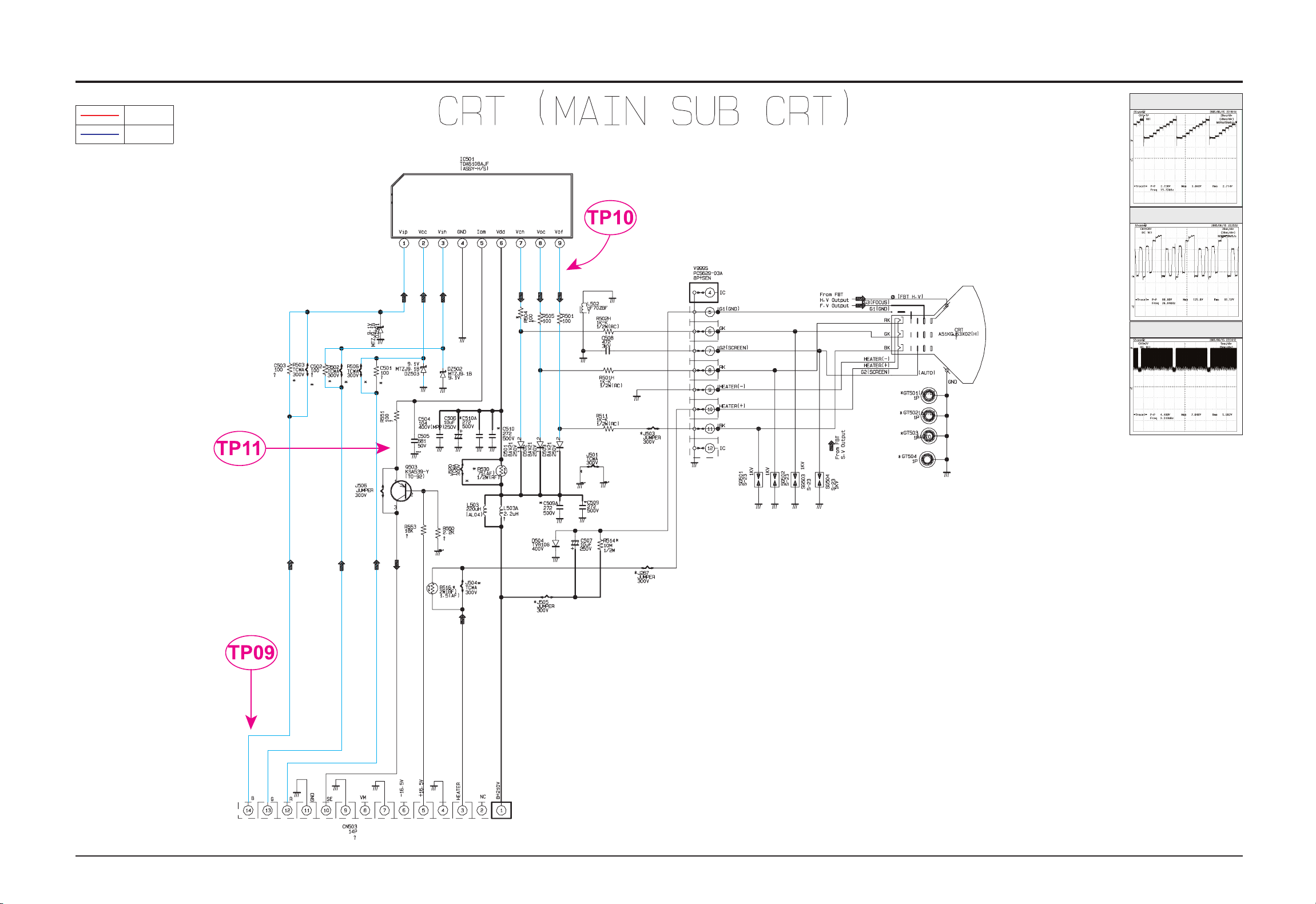
10-3 PIP & CRT Block
This Document can not be used without Samsung’s authorization.
TP09
TP10
TP11
Power
Signal
Schematic Diagram
10-4 Samsung Electronics
10-4 AV & Sound Block
This Document can not be used without Samsung’s authorization.
Reference Information
Samsung Electronics 14-1
14. Reference Information
14-1 Other issues related to other products
Problem Descriptions
A fixed screen can cause
permanent damage to the TV
Braun tube.
Braun, PDP and LCD TVs can all be damaged. When a still image is displayed in a sequence,
this can leave stains or after-images due to the characteristics of the panel.
However, the DLP TV has the advantage that no stains or after-images are left on the screen.
The DLP TV has mirror pixels on the DMD panel that project the beam onto the screen, in
which the mirror is a digital representation of 0s and 1s, leaving no trace of light.
The mirror returns to a blank state so that no stains or after-images are left.
■ SD/HD broadcasts and the TV's display capability are related
1. A digital broadcast should be transmitted in wide screen (an aspect ratio of 16:9) HD. If the broadcasting station converts a
conventional program created in normal screen (aspect ratio of 4:3) into a digital signal and broadcasts the signal, the left and
right of the picture will not be displayed.
This symptom also appears in other manufacturer's TV's. The three appliance companies are trying to resolve the problem
through the Ministry of Information and Communication.
* When watching an SD (normal) broadcast through a Digital (Wide) TV (480P normal broadcast)
* When watching an SD (normal) broadcast through a Digital Ready (Wide) TV (Using a set-top-box)
* When watching an analog (normal) broadcast through a wide TV
(When watching a broadcast after changing the aspect ratio of the TV from 16:9 (wide screen) to 4:3)
2. When watching a DVD title or video tape in wide screen (21:9) through a wide (16:9) TV, watching video from a computer or
game console by selecting the aspect ratio to 4:3, or watching video from a DVD, VCR, computer or game console through a
wide TV by selecting the aspect ratio to normal (4:3) or wide (21:9), the left and right, or top and bottom of the picture will not be
displayed.
This symptom appears in other manufacturer's TV's. The three appliance companies are trying to resolve the problem through
the Ministry of Information and Communication.
■ Changing the Order of the Picture Size for DTV 1080i/720p Sources
■ Restrictions
1. When you want to change the picture size in PIP 'ON', you must turn the PIP off before changing the size.
However, you can change the main picture size even in PIP ON for products with no restrictions.
2. When the picture size is not Normal (4:3 for 4:3 display devices, 16:9 for 16:9 display devices) and you turn PIP on, the picture
size is changed to Normal.
However, you can turn PIP on without changing the picture size for products with no restrictions.
4. The picture size can be changed even in the blue screen.
However, the picture size should be controlled by the product specifications if the change is impossible due to hardware
restrictions.
4:3(Normal) Zoom

Reference Information
14-2 Samsung Electronics
Digital Broadcast
Digital Broadcast is a television broadcasting signal digitized
and transmitted according to the United States' terrestrial digital
broadcast standard, or ATSC.
Mono
A type of audio interface that transmits audio signals through a
single channel.
Through a mono interface, it is hard to experience stereophonic
sound and sound is played only by one speaker.
Reception Sensitivity Amplification
A signal amplification technique that amplifies weak broadcasting signals by applying satellite technology to provide a better
visual quality even for users in regions where only weak broadcasting signals are available.
Stereo
A type of audio interface that transmits audio signals through 2
channels.
Stereo transmits audio signals for the right and left channels so
that you can experience stereophonic sound, and the sound is
played with 2 speakers.
Analog Broadcast
Analog Broadcast is a television broadcasting signal transmitted according to the NTSC standard.
ANTENNA IN Port
A port to connect the TV aerial using a coaxial cable. It is generally used to watch public broadcast programs.
English Caption
A function that shows English caption or text information included in the broadcasting signal or video tape. You can use this
function to study English by watching AFKN or CC marked
video tapes.
Video/Audio Ports
You may experience poor visual and audio quality when watching a video tape on channel 3 or 4 through the antenna cable.
You can experience better visual and audio quality connecting
the TV and VCR through the Video/Audio ports. The video port
is distinguished by the color yellow, and the audio ports are distinguished by the white (left) and red colors (right).
External Input
External Input is connecting video devices such as a VCR,
camcorder, DTV receiver, DVD, etc. as a video source.
Satellite Broadcast
Satellite Broadcast transmits programs via satellite so that the
broadcast is viable in all areas at a high visual and sound quality. It provides approximately 100 channels including public
broadcast channels. To view satellite broadcast, you have to
install an additional receiver.
Wired Broadcast
Satellite Broadcast refers to movie, entertainment and educational programs transmitted by the broadcasting station in a
hotel or school.
Audio Multimix
Audio Multimix provides 2 languages for audio when broadcasting a foreign movie, drama, news, etc. You can select and listen to one of the supported languages or you can select and
listen to both languages simultaneously.
Component Port (Green, Blue, Red)
The Component Port separately transmits the luminance signal
and provides the best quality of all video connection types.
Cable Broadcast
Cable Broadcast transmits programs via cable instead of radio
wave. To view a cable broadcast, you need to subscribe to your
local cable broadcast service provider and install an additional
receiver.
Tuner
A device that enables selecting a specific frequency for a channel on a TV or radio.
Anynet
Anynet is an AV network system that enables the easy-to-use
AV interface for users by controlling connected AV devices
through the Anynet menu when AV devices of Samsung
Electronics are connected.
DVD (Digital Versatile Disc)
DVD is a large capacity media that can save multimedia content such as video, game, audio applications, etc. using MPEG2 video compression technology on a CD-sized disc.
S-VIDEO IN Port
This is called super video. S-Video is a type of video signal
which has the video luminance and color signals separated in
order to provide a better visual quality.
VHF/UHF
VHF refers to TV channels 2 to 13, and UHF refers to TV channels 14 to 69.
14-2 Technical Terms
Product Specification
Samsung Electronics 2-1
2. Product Specification
2-1 Product Features
Block Specfication Core Parts Remark
CRT 29" FLAT AK CRT GREEN CRT
RF Part 1TUNER F/S TUNER TDQ-6F/13F2S
Power
WORLD WIDE INPUT VOLTAGE RANGE
STD-BY : 5W UNDER
STR-W6750F
Video
- MULTI SYSTEM(NT/PAL)
- 1H Comb Filter
TDA12005PQ,
TDA12015PQ
Audio
- Output : 5W/10W/15W X2
- BTSC/SAP STEREO : PSEUDO STEREO, TURBO PLUS
TDA12005PQ,
TDA12015PQ,
TDA7297SA
Cabinet - 29" CABINET
Other
- BASIC MODEL : CL29M21FQ2XXAX
- UOC3 with a built-in MSP
- TURBO → TURBO PLUS
■ Core Parts Functions
- TDA12005PQ : Video/Sound Processing and MICOM (NTSC)
- TDA12015PQ : Tri-noma
- STR-W6750F : SMPS Power STR
- TDA7297SA(or 7266) : 5W ~ 15W Sound Output BTL AMP
- 24C16 : 16K EEPROM
- LA78040 : Vertical Deflection AMP
- C5936 : H-OUT S/W TR
- TDA-6F/13F2S : F/S PAL Tuner
- TDA6108AJF : R/G/B Drive AMP IC

Product Specification
2-2 Samsung Electronics
2-2 Key Features
Model CL-29K40MQ
Voltage AC100-240V
Frequency of Operation 50/60 Hz
Power Consumption 110 Watts
Dimensions (mm/inches)
766 X 558 X 586/
30.16 X 21.97 X 23.07
Weight (Kg/ lbs) 41/90.39
■ Hardware Configuration
- 1 Chip : UOC3 TDA12005PQ(CHROMA, IF+Deflection, MICOM, MSP)
- Tuner : TDA-6F/13F2S
- SOUND AMP : TDA7297SA(ZIP, 15P, -, DUAL, 32dB, PLASTIC, 20V, 30W)
- SMPS Controller : STR-W6750F(6P, TO-3P-F7L)
- Vertical AMP : LA78045(TO220, 7P, 15V)
- Flyback Trans : FOK14B001(11P, 27KV)
- CRT : A51QDX993X(A) (AK, 1H Single Focus)
■ Software Configuration
- MCU : 80C51-controller core
- Data Capture for US Closed Caption
- 0.4883s machine cycle
■ Picture
- Enhance : DNIe Jr.(Digital Natural Image Engine)
- System : NTSC3.58
- Interlaced(60Hz)
- AKB(Auto Kinetic Bais)
- Comb Filter : 1H Comb Filter
- 4:3/Zoom
■ Sound
- BTSC/SAP-STEREO
- Output : 5/10/15W X 2CH
- Auto Stereo, Sound Equalizer, Auto Mute, Auto Volume Limit, PSEUDO STEREO, TURBO PLUS
■ Feature
- Composite (RCA A/V, DVD), S-Video(Y/C)
- Picture Size : Zoom/4:3
- Auto Serch
- Sleep Timer : 180 Min
- Clock Setting
- Blue Screen, Melody On-Off, Picture Mode Select
■ In/Out Terminals
- Rear : 2RCA/DVD/S-VHS
- Front or Side A/V Input(Side A/V Preferability)
■ Remocon
- Universal Interface TM75
■ Power Consumption : 105W
Product Specification
Samsung Electronics 2-3
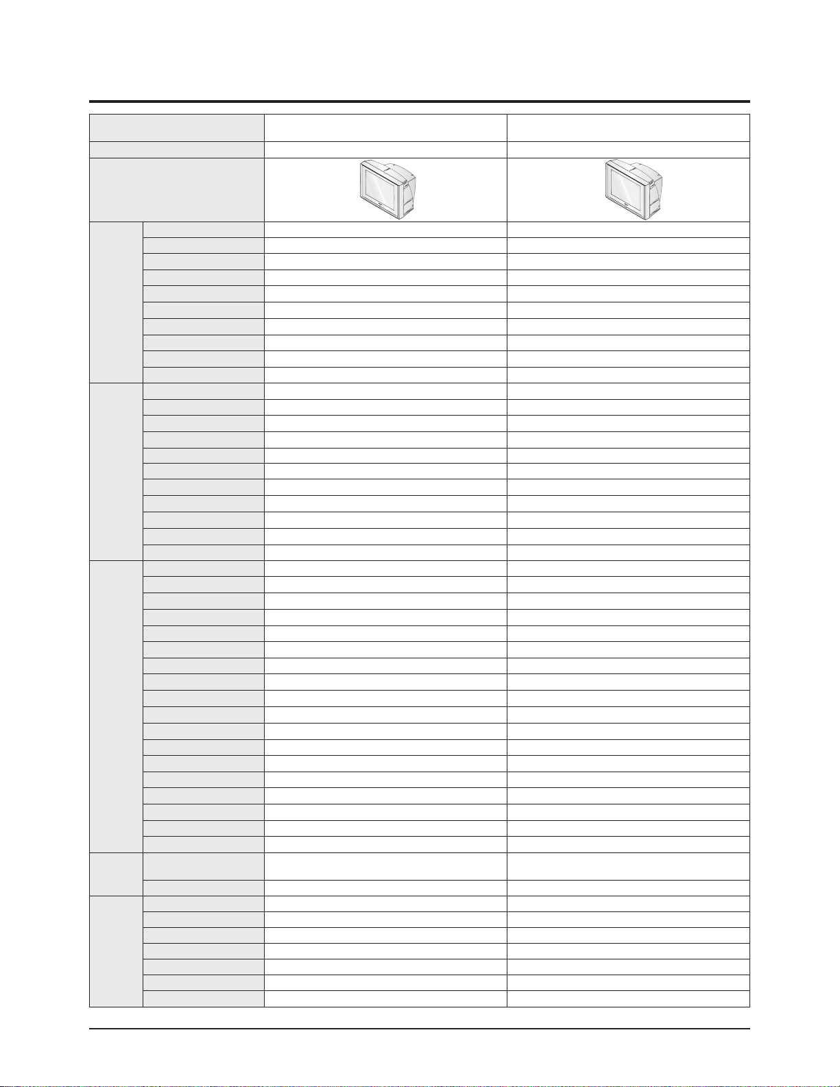
2-3 Specifications Analysis
Model CL29M21PQ CL-29K40MQ
Chassis KS7A K16A
Design
Picture
Screen Size 29" 29"
Pure Flat CRT
○ ○
DNIe Jr.
○ ○
Comb Filter 1H 1H
Velocity Modulation
× ×
Video Noise Reduction
○ ○
Auto Kinetic Bias
○ ○
Color Tone Control
○ ○
Tilt Control
× ×
Picture Mode 4 Mode 4 Mode
Sound
MTS/SAP
○ ○
Output Power(RMS) 15W x 2 15W x 2
Tweeter
× ×
BBE
× ×
Surround Surround Surround
Sound Mode 5 Mode 5 Mode
Graphic Equalizer
× ×
Sub-Woofer Speaker
× ×
Auto Volume Leveler
○ ○
Melody On/Off
○ ○
Turbo Sound
○ ○
Convenience
PIP 2T (Optional)
×
Plug & Play
○ ○
Zoom Mode
○ ○
OSD Demo
○ ○
OSD Language E/F/S E/F/S
Previous Channel
○ ○
Closed Caption
○ ○
On/Off Timer
○ ○
Sleep Timer
○ ○
Auto Power Off
○ ○
Clock
○ ○
Channel Scan
× ×
Self-diagnostic System
○ ○
Remote Control TM76 TM75
Remote Surf
○ ○
Channel Labelling
○ ○
Blue Screen
○ ○
Rack
× ×
Voltage
Voltage
AC100-240V
AC120V (Mexico)
AC100-240V
Stand-by under 3W under 5W
Jacks
RF Input R1 R1
A/V Input S1/R2 S1/R2
Monitor Output R1 R1
S-VHS Input R1 R1
Headphone S1 S1
DVD Input
○ ○
PC Input(VGA)
× ×
Product Specification
2-4 Samsung Electronics
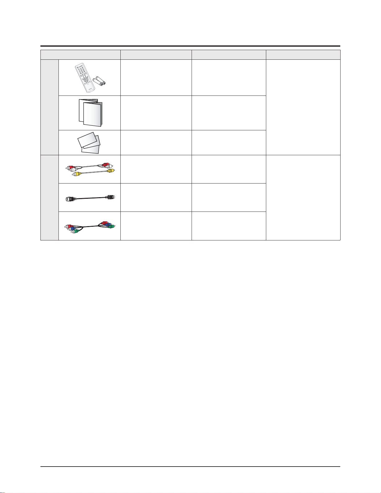
2-4 Accessories
Accessories Item Item code Remark
Supplied Accessories
Remote Control
AAA Alkaline Battery (2)
AA59-00385A
4301-000121
Samsung Service center
Owner's Instructions AA68-03858A
Warranty Card AA68-03727A
Accessories that can be purchased
additionally
Video Cable /
Audio Cable
-
Internal shopping mallAntenna Cable -
Component Cable -

1. Make sure all protective devices are properly installed
including non-metallic handles and compartment covers
when installing or re-installing the chassis or chassis
assemblies.
2. Make sure that no gaps exist between the cabinets for
children to insert their fingers in to prevent children from
receiving electric shocks. Gaps mentioned above include
ventilation holes of a too great magnitude between the
vaccum tube and the cabinet mask, and the improper
installation of the rear cabinet.
Errors may occur when the resistance is below 1.0 ㏁ or
over 5.2 ㏁.
In these cases, make sure that the device is repaired
before sending it back to the customer.
3. Check for Electricity Leakage (Figure 1-1)
Warning: Do not use an insulated transformer for checking the leakage. Use only those current leakage testers
or mirroring systems that comply with ANSIC 101.1 and
the Underwriter Laboratory's specifications (UL1410,
59.7).
Fig. 1-1 AC Leakage Test
4. A high voltage is maintained within the specified limits
using safety parts, calibration and tolerances. When
voltage exceeds the specified limits, check each special
part.
5. Warning for Engineering Changes:
Never make any changes or additions to the circuit
design or the internal part for this product.
Ex: Do not add any audio or video accessory
connectors. This might cause physical damage.
Furthermore, any changes or additions to the original
design/engineering will invalidate the warranty.
6. Warning - Hot Chassis:
Some TV chassis are directly connected to one end of
the AC power cord for electrical reasons.
Without insulated transformers, the product can only be
repaired safely when the chassis is connected to the
earthed end of the AC power source.
To make sure the AC power cord is properly connected,
follow the instructions below. Use the voltmeter to
measure the voltage between the chassis and the
earthed ground. If the measurement is over 1.0V, unplug
the AC power cord and change the polarity before reinserting it. Measure the voltage between the chassis
and the ground again.
7. Some TV chassis are shipped with an additional
secondary grounding system. The secondary system is
adjacent to the AC power line. These two grounding
systems are separated in the circuit using an
unbreakable/unchangeable insulation material.
8. When any parts, material or wiring appear overheated or
damaged, replace them with new regular ones
immediately. When any damage or overheating is
detected, correct this immediately and make a regular
check of possible errors.
9. Check for the original shape of the lead, especially that
of the antenna wiring, any sharp edges, the AC power
and the high voltage power. Carefully check if the wiring
is too tight, incorrectly placed or loose. Never change the
space between the part and the printed circuit board.
Check the AC power cord for possible damages. Keep
the part or the lead away from any heat-emitting
materials.
Precaution
Samsung Electronics 1-1
To avoid possible damages or electric shocks or exposure to radiation, follow the instructions below with regard to safety,
installation, service and ESD.
1. Precaution
1-1 Safety Precautions
(READING SHOULD
DEVICE
UNDER
TEST
EXPOSED METAL
2-WIRE CORD
ALSO TEST WITH
PLUG REVERSED
(USING AC ADAPTER
PLUG AS REQUIRED)
TEST ALL
SURFACES
LEAKAGE
CURRENT
TESTER
NOT BE ABOVE
0.5mA)
EARTH
GROUND

10. Safety Indication:
Some electrical circuits or device related materials
require special attention to their safety features, which
cannot be viewed by the naked eye. If an original part is
replaced with another irregular one, the safety or
protective features will be lost even if the new one has a
higher voltage or more watts.
Critical safety parts should be bracketed with ( ).
Use only regular parts for replacements (in particular,
flame resistance and dielectric strength specifications).
Irregular parts or materials may cause electric shock or
fire.
Precaution
1-2 Samsung Electronics
!

1. The service instructions are printed on the cabinet, and
should be followed by any service personnel.
2. Make sure to unplug the AC power cord from the power
source before starting any repairs.
(a) Remove or re-install parts or assemblies.
(b) Disconnect the electric plug or connector, if any.
(c) Connect the test part in parallel with the electrolytic
capacitor.
3. Some parts are placed at a higher position than the
printed board. Insulated tubes or tapes are used for this
purpose. The internal wiring is clamped using buckles to
avoid contact with heat emitting parts. These parts are
installed back to their original position.
4. After the repair, make sure to check if the screws, parts
or cables are properly installed. Make sure no damage is
caused to the repaired part and its surroundings.
5. Check for insulation between the blade of the AC plug
and that of any conductive materials (i.e. the metal
panel, input terminal, earphone jack, etc).
6. Insulation Check Process: Unplug the power cord from
the AC source and turn the switch on. Connect the insulating resistance meter (500v) to the AC plug blade.
The insulating resistance between the blade of the AC
plug and that of the conductive material should be more
than 1 ㏁.
7. Any B+ interlock should not be damaged.
If the metal heat sink is not properly installed, no
connection to the AC power should be made.
8. Make sure the grounding lead of the tester is connected
to the chassis ground before connecting to the positive
lead. The ground lead of the tester should be removed
last.
9. Beware of risks of any current leakage coming into
contact with the high-capacity capacitor.
10. The sharp edges of the metal material may cause
physical damage, so ensure wearing protective gloves
during the repair.
Precaution
Samsung Electronics 1-3
Warning 1: First carefully read the "Safety Instruction" in this service manual.
When there is a conflict between the service and the safety instructions, follow the safety instruction at all times.
Warning 2: Any electrolytic capacitor with the wrong polarity will explode.
1-2 Servicing Precautions

1-3 Static Electricity Precautions
1. Some semi-conductive ("solid state") devices are
vulnerable to static electricity. These devices are known
as ESD. ESD includes the integrated circuit and the field
effect transistor. To avoid any materials damage from
electrostatic shock, follow the instructions described
below.
2. Remove any static electricity from your body by
connecting the earth ground before handling any
semi-conductive parts or ass'ys. Alternatively, wear a
dischargeable wrist-belt.
(Make sure to remove any static electricity before
connecting the power source - this is a safety instruction
for avoiding electric shock)
3. Remove the ESD ass'y and place it on a conductive
surface such as aluminum foil to prevent accumulating
static electricity.
4. Do not use any Freon-based chemicals.
Such chemicals will generate static electricity that
causes damage to the ESD.
5. Use only grounded-tip irons for soldering purposes.
6. Use only anti-static solder removal devices.
Most solder removal devices do not support an
anti-static feature. A solder removal device without an
anti-static feature can store enough static electricity to
cause damage to the ESD.
7. Do not remove the ESD from the protective box until the
replacement is ready. Most ESD replacements are
covered with lead, which will cause a short to the entire
unit due to the conductive foam, aluminum foil or other
conductive materials.
8. Remove the protective material from the ESD
replacement lead immediately after connecting it to the
chassis or circuit ass'y.
9. Take extreme caution in handling any uncovered ESD
replacements. Actions such as brushing clothes or lifting
your leg from the carpet floor can generate enough static
electricity to damage the ESD.
Precaution
1-4 Samsung Electronics
CAUTION
These servicing instructions are for use by
qualified service personnel only.
To reduce the risk of electric shock do not
perform any servicing other than that contained in the
operating instructions unless you are qualified to do so.

Precaution
Samsung Electronics 1-5
1-4 Installation Precautions
1. For safety reasons, more than two people are required
for carrying the product.
2. Keep the power cord away from any heat emitting
devices, as a melted covering may cause fire or electric
shock.
3. Do not place the product in areas with poor ventilation
such as a bookshelf or closet. The increased internal
temperature may cause fire.
4. Bend the external antenna cable when connecting it to
the product. This is a measure to protect it from being
exposed to moisture. Otherwise, it may cause a fire or
electric shock.
5. Make sure to turn the power off and unplug the power
cord from the outlet before repositioning the product.
Also check the antenna cable or the external connectors
if they are fully unplugged. Damage to the cord may
cause fire or electric shock.
6. Keep the antenna far away from any high-voltage cables
and install it firmly. Contact with the high-voltage cable or
the antenna falling over may cause fire or electric shock.
7. Check the basics of the screen test.
- Image position/size, Tilt adjustment

1-6 Samsung Electronics
MEMO
PCB Diagram
Samsung Electronics 9-1
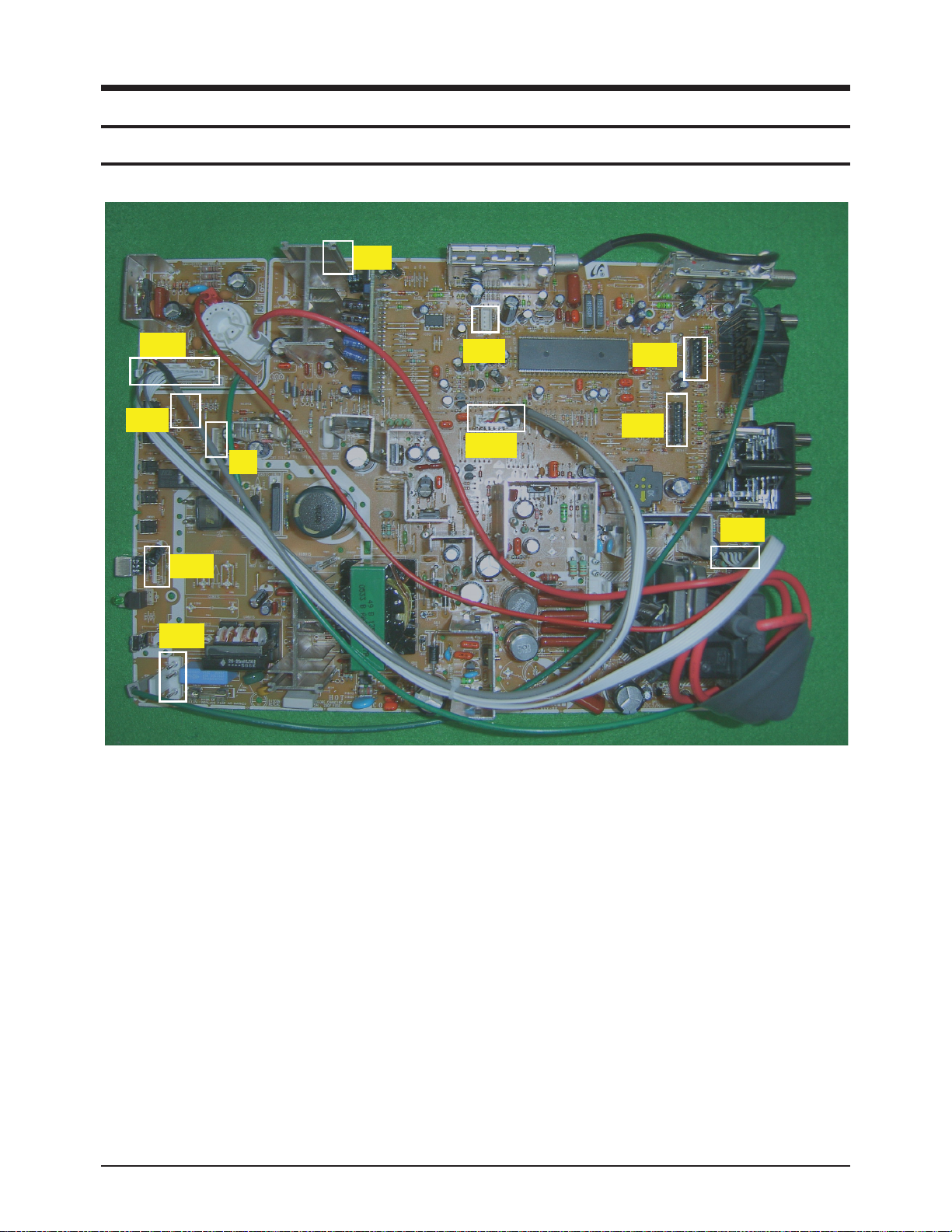
9. PCB Diagram
9-1 Main Board
9-1-1 Assy Main Board
■ The Board that Controls Various Signals & Power for Product Operations
9-1-2 Names & Roles of Key Parts
* GT801 : A3 pin port connected to the Master Ass'y, which handles Master Power On/Off.
* CN601 : A4 pin port connected to the Speaker.
* CN902 : A4 pin port connected to the Control Ass'y, which delivers the necessary signal to KEY-IN1, KEY-IN2 Control.
* CN901 : A5 pin port connected to the Control Ass'y, which delivers the necessary signal to the remote control and the Led
control.
* CN602 : A5 pin port connected to AV Ass'y.
* CN701 : A8 pin port connected to the AV Ass'y, which receives AV2 external input.
* CN702 : A7 pin port connected to the AV Ass'y, which receives S-VHS external input.
* CN501 : A8 pin port connected to the CRT Ass'y which outputs the R/G/B signal to the CRT Ass'y for display.
In addition, this port outputs the necessary TILT, VM, and Power signals to the CRT Drive.
* CN502 : A6 pin port connected to the CRT Ass'y. Through this port, the power from the Deflection Block is supplied to drive
the CRT AMP.
* CN503 : A14 pin port connected to the CRT Ass'y.
* FN1 : A4 pin port connected to the Tilt Coil.
CN601
CN503
CN902
FN1
CN901
GT801
CN900
CN501A
CN702
CN701
CN502
 Loading...