

SAMSUNG CL21K3WDX-STR, CL2645W7X-STR, CL2945W7X-STR Service Manual

COLOR TELEVISION RECEIVER
Chassis : KS2A
Model : CL21K3WDX/STR
CL2645W7X/STR
CL2945W7X/STR
COLOR TELEVISION RECEIVER CONTENTS
Precautions
Reference Information
Specifications
Alignment and Adjustments
Troubleshooting
Exploded Views and Parts List
Electrical Parts List
Block Diagrams
Wiring Diagram
Schematic Diagrams
1.
2.
3.
4.
5.
6.
7.
8.
9.
10.

ELECTRONICS
© Samsung Electronics Co., Ltd. AUG. 2001
Printed in Korea
3KS2A-SMX-2110

Reference Information
Samsung Electronics 2-1
2. Reference Information
2-1 Tables of Abbreviations and Acronyms
A
Ah
Å
dB
dBm
°C
°F
°K
F
G
GHz
g
H
Hz
h
ips
kWh
kg
kHz
kΩ
km
km/h
kV
kVA
kW
I
MHz
Ampere
Ampere-hour
Angstrom
Decibel
Decibel Referenced to One
Milliwatt
Degree Celsius
Degree Fahrenheit
degree Kelvin
Farad
Gauss
Gigahertz
Gram
Henry
Hertz
Hour
Inches Per Second
Kilowatt-hour
Kilogram
Kilohertz
Kilohm
Kilometer
Kilometer Per Hour
Kilovolt
Kilovolt-ampere
Kilowatt
Liter
Megahertz
MV
MW
MΩ
m
µA
µF
µH
µm
µs
µW
mA
mg
mH
mI
mm
ms
mV
nF
Ω
pF
Ib
rpm
rps
s
V
VA
W
Wh
Megavolt
Megawatt
Megohm
Meter
Microampere
Microfarad
Microhenry
Micrometer
Microsecond
Microwatt
Milliampere
Milligram
Millihenry
Milliliter
Millimeter
Millisecond
Millivolt
Nanofarad
Ohm
Picofarad
Pound
Revolutions Per Minute
Revolutions Per Second
Second (Time)
Volt
Volt-ampere
Watt
Watt-hour
Table 2-1 Abbreviations

Reference Information
2-2 Samsung Electronics
Table 2-2 Table of Acronyms
ABL
AC
ACC
AF
AFC
AFT
AGC
AM
ANSI
APC
APC
A/V
AVC
BAL
BPF
B-Y
CATV
CB
CCD
CCTV
Ch
CRT
CW
DC
DVM
EIA
ESD
ESD
FBP
FBT
FF
FM
FS
GND
G-Y
H
HF
HI-FI
IC
IC
IF
Automatic Brightness Limiter
Alternating Current
Automatic Chroma Control
Audio Frequency
Automatic Frequency Control
Automatic Fine Tuning
Automatic Gain Control
Amplitude Modulation
American National Standards Institute
Automatic Phase Control
Automatic Picture Control
Audio-Video
Automatic Volume Control
Balance
Bandpass Filter
Blue-Y
Community Antenna Television (Cable TV)
Citizens Band
Charge Coupled Device
Closed Circuit Television
Channel
Cathode Ray Tube
Continuous Wave
Direct Current
Digital Volt Meter
Electronics Industries Association
Electrostatic Discharge
Electrostatically Sensitive Device
Feedback Pulse
Flyback Transformer
Flip-Flop
Frequency Modulation
Fail Safe
Ground
Green-Y
High
High-Frequency
High Fidelity
Inductance-Capacitance
Integrated Circuit
Intermediate Frequency
I/O
L
L
LED
LF
MOSFET
MTS
NAB
NEC
NTSC
OSD
PCB
PLL
PWM
QIF
R
RC
RF
R-Y
SAP
SAW
SIF
SMPS
S/N
SW
TP
TTL
TV
UHF
UL
UV
VCD
VCO
VCXO
VHF
VIF
VR
VTR
VTVM
TR
Input/output
Left
Low
Light Emitting Diode
Low Frequency
Metal-Oxide-Semiconductor-Field-Effect-Tr
Multi-channel Television Sound
National Association of Broadcasters
National Electric Code
National Television Systems Committee
On Screen Display
Printed Circuit Board
Phase-Locked Loop
Pulse Width Modulation
Quadrature Intermediate Frequency
Right
Resistor & Capacitor
Radio Frequency
Red-Y
Second Audio Program
Surface Acoustic Wave(Filter)
Sound Intermediate Frequency
Switching Mode Power Supply
Signal/Noise
Switch
Test Point
Transistor Transistor Logic
Television
Ultra High Frequency
Underwriters Laboratories
Ultraviolet
Variable-Capacitance Diode
Voltage Controlled Oscillator
Voltage Controlled Crystal Oscillator
Very High Frequency
Video Intermediate Frequency
Variable Resistor
Video Tape Recorder
Vacuum Tube Voltmeter
Transistor
REMARK
Refer to Table 2-3-1
Refer to Table 2-3-2
VM Option
DH01
Option
DDR01
LOC. NO
IC201S
IC601
IC901
IC902
IC602
HIC201
IC301
Q401
D409
IC401
Q404
IC801S
D801S
PC801S
IC805
D806
D807
D805
IC804
IC803
IC903
IC904
Q909
Q910
TU01
D813
Table 2 - 3 IC Line - Up
NO
1
Reference Information
Samsung Electronics 2-3
2-2 IC Line Up
BOARD
MAIN
SPEC
VDP3112B
MSP3440D
SDA555X
KS24L161
TDA7297
DRGB001
LA7845
KSD5703
FMP-3FU
KA393
IRF620
3S1265R
RBV606
PC123Y
KA78R05
FML-G12S
FMG-G26S
KA7806
KA78R08
KA78RM33
KIA7025AP
2N7000
TCPN3081PA09A(S)
FML-G12S
DESCRIPTION
Video Processor
NTSC Sound Processor
MICOM, Caption (MTP)
EEPROM
Audio AMP
RGB Drive AMP Hybrid IC
Vertical IC
Horizontal Drive IC
E/W Drive IC
SPS Controllor
Bridge Diode
Photo Coupler
5V Controlled Regulator
Rectifier Diode
6V Regulator
8V Controlled Regulator
3.3V Regulator
MICOM Reset IC
IIC Level Shifter
Main Tuner with IF Block
Rectifier Diode
2-4 Samsung Electronics
Table 2 - 3 IC Line - Up
DESCRIPTION
Video Output AMP R.G.B Drive
Push-Pull (VM)
Video Switching IC with Adder Output
High-end Picture-In Picture IC
LOC. NO
IC501
IC502
IC503
QF04
QF05
ICS01
ICP01
SPEC
TDA6101Q
2SC2344
2SA1011
TEA6425
SDA9388X
REMARK
Option
Option
Option
BOARD
CRT
V-S/W
PIP
Reference Information
NO
2
3
4
SPEC
VDP3108B
VDP3130Y
FUNCTION
Basic 1H Comb Filter
2H Comb Filter, DVD Input
REMARK
Table 2-3-1 VIDEO IC
SPEC
TDA7297
TDA7266S
FUNCTION
7W x 2CH, 10W x 2CH
3W x 2CH, 5W x 2CH
REMARK
Table 2-3-2 SOUND AMP

Specifications
Samsung Electronics 3-1
3. Specifications
Specifications are subject to change.
Television
System
Antena Input
Multi
Power
Consumption
Requirements
Frequency
Sound
Output
Effect
Jacks
Front
(AV2)
Back
NTSC-M, PAL N.M
160W (Applied When 29” Flat)
Free Volts(100V-240Volts)
Free Voltage
50/60Hz
15W x 2CH
10W x 2CH
5W x 2CH
Vitual Dolby
Turbo Sound
Pseudo Stereo
RCA Input
S-VHS
Head-Phone
2 AV Input
DVD Input(YPbPr)
AV2 Monitor Audio Output
S-VHS
75ohms, Coaxial Cable
Not Present R815
Option
Option
Option
Option
Option
Option
Option
Option

3-2 Samsung Electronics
MEMO

Alignment and Adjustments
Samsung Electronics 4-1
4. Alignment and Adjustments
4-1 General Alignment Instructions
1. Usually, a color TV-VCR needs only slight
touch-up adjustment upon installation. Check
the basic characteristics such as height,
horizontal and vertical sync and focus.
2. Observe the picture for good black and white
details. There should be objectionable color
shading; if color shading is present,
demagnetize, perform purity and convergence
adjustments described below.
3. Use the specified test equipment or its
equivalent.
4. Correct impedance matching is essential.
5. Avoid overload. Excessive signal from a
sweep generator might overload the front-end
of the TV. When inserting signal markers, do
not allow the marker generator to distort test
results.
6. Connect the TV only to an AC power source
with voltage and frequency as specified on the
backcover nameplate.
7. Do not attempt to connect or disconnect any
wires while the TV is turned on. Make sure
that the power cord is disconnected before
replacing any parts.
8. To protect against shock hazard, use an
isolation transformer.
4-2 Automatic Degaussing
A degaussing coil is mounted around the
picture tube, so that external degaussing after
moving the TV should be unnecessary. But
the receiver must be properly degaussed upon
installation.
The degaussing coil operates for about 1
second after the power is switched ON. If the
set is moved or turned in a different direction,
the power should be OFF for at least 10
minutes.
If the chassis or parts of the cabinet become
magnetized, poor color purity will result. If
this happens, use an external degaussing coil.
Slowly move the degaussing coil around the
faceplate of the picture tube and the sides and
front of the receiver. Slowly withdraw the coil
to a distance of about 6 feet before turning
power OFF.
If color shading persists, perform the
following Color purity and Convergence
adjustments.
4-3 High Voltage Check
CAUTION : There is no high voltage adjustment
on this chassis. The B+ power supply should be
+135 volts (with full color- bar input and normal
picture level).
1. Connect a digital voltmeter to the second
anode of the picture tube.
2. Turn on the TV. Set the Brightness and
Contrast controls to minimum (zero beam
current).
3. Adjust the Brightness and contrast controls to
both extremes. Ensure that the high voltage
does not exceed 30 KV under any conditions.
Alignment and Adjustments
4-2 Samsung Electronics
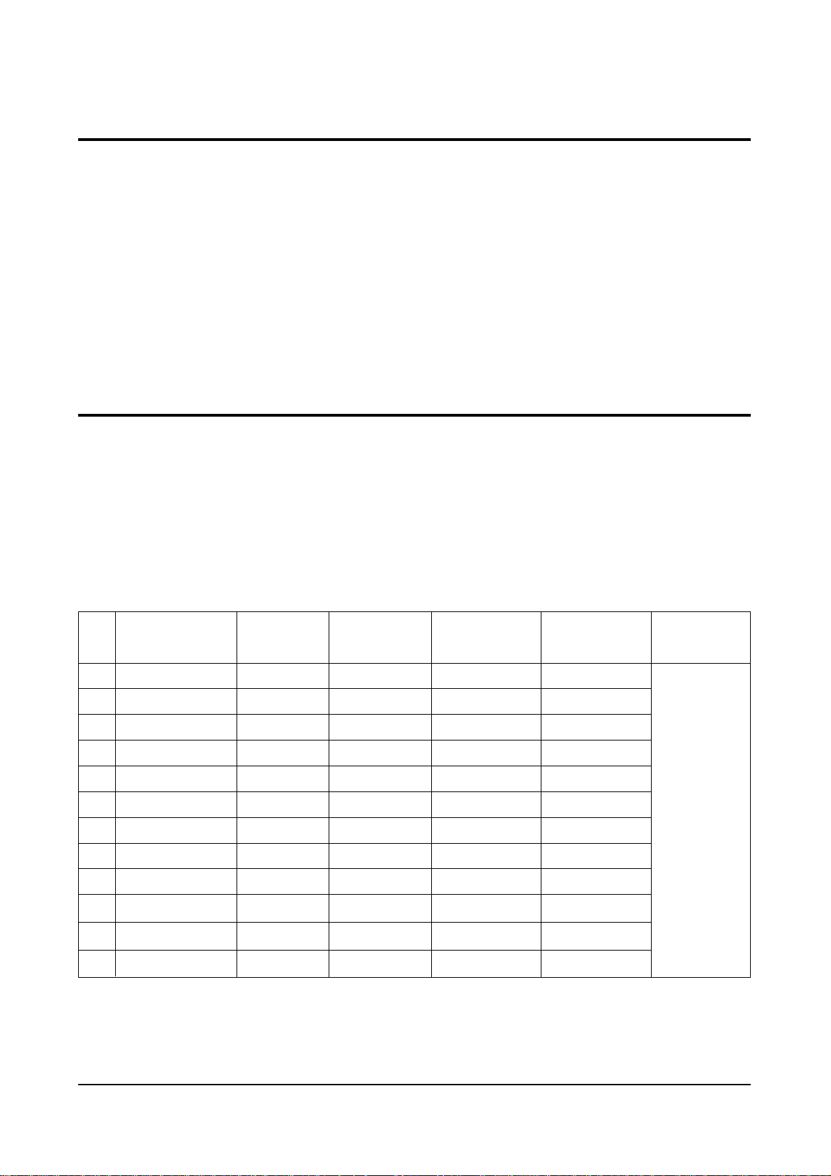
4-5 SCREEN Adjustment
1. Input Toshiba Pattern
2. Enter “Service Mode”.(Refer to “4-8-1 Service Mode”)
3. Select “G2-Adjust”.
4. Set the values as below.
4-4 FOCUS Adjustment
1. Input a black and white signal.
2. Adjust the tuning control for the clearest picture.
3. Adjust the FOCUS control for well defined scanning lines in the center area of the screen.
5. Turn the SCREEN VR until “MRCR G B” and “MRWDG” are green and those value are about 100.
(The incorrect SCREEN Voltage may result that “MRCR G B” and “MRWDG” should be red)
INCH / CRT
14” / SDI
15PF / SDI
21” 1.7R / SDI
20V 10.0R/SDI
21PF / TSB
21PF / LG
21PF / SDI
25PF / SDI
27V 1.3R / SDI
27V 1.0R/SDI
25V 1.0R/SDI
23V 1.3R/SDI
No
1
2
3
4
5
6
7
8
9
10
11
12
IBRM
205
220
220
205
220
230
220
210
210
210
210
205
WDRV
35
35
35
35
35
35
35
35
35
35
35
35
CDL
100
180
180
115
180
230
210
160
170
150
150
120
COLR G B
(Smallest Value)
100
100
100
120
65
65
65
120
150
180
180
140
Table 1. Screen Adjustment Table
REGION
Normal

Alignment and Adjustments
Samsung Electronics 4-3
4-6 E2PROM (IC902) Replacement
1. When IC902 is replaced, all adjustment data revert to the initial values.
So, all adjustment values when servicing should be readjusted.
2. After IC902 is replaced, connect the AC power supply cord.
3. Turn the power switch ON.
4. In stand-by, warm up the TV for at least 10 seconds.
5. Power on the TV.
4-7 White Balance Adjustment
■ Equipment : Color-Analyzer (CA-100)
■ Input Signal : Pattern signal (Toshiba pattern)
1. Select STANDARD from the menu.
2. Input an 100% White pattern.
3. Enter the “Service Mode”. (Refer to “4-8 Service Mode”)
4. Warm up the TV set at least for 30 minutes.
5. Input a Toshiba pattern signal.
6. Enter the “Video Adjust1”.
- Adjust “Sub Contrast” so that Y (luminance) becomes 65 ft ±3.
- Use “Red Drive” and “ Blue Drive” to adjust High-Light (x : 265, y : 265)
- Adjust “Sub Bright” so that Y (luminance) becomes 1.2ft ± 0.3.
- Use “Red Cutoff” and “Blue Cutoff” to adjust Low-Light (x : 265, y : 265).
7. Adjust CA-100 so that the final adjustment value can be fixed.
8. Use the Channel Up/Down (▲/▼) buttons to move the cursor on the adjustment modes.
9. Use the Volume +/- buttons to change the adjustment value.
Alignment and Adjustments
4-4 Samsung Electronics
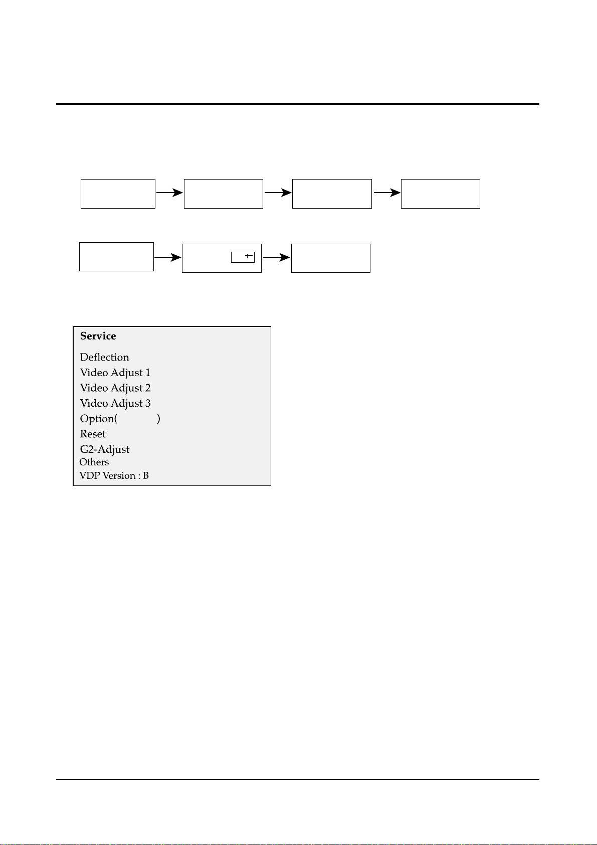
4-8 Factory Adjustment
1. To enter the “Service Mode”, Press the remote-control keys in this sequence :
- If you do not have Factory remote-control
- If you have Factory remote-control
2. After the Service Mode is entered, the initial screen is as shown in the figure below.
3. Use the Channel Up/Down buttons to move the cursor in the adjustment parameters.
Note :
- When CRT, CRT PCB, FBT, E
2
PROM (sometimes MICOM) is replaced, the adjustment values
should be controlled.
- After the Service adjustment is completed, Do not select “Reset” in the service mode menu.
(After above procedure is done, power is on initially and the “Plug and Play” will be operated.)
4-8-1 Service Mode
*
These hexa digits are check sum value which
depends on the MICOM version.
If check sum value is changed, the value of
E
2
PROM Data newly initialed.
PICTURE OFF PICTURE ON
PICTURE ON
MUTE 1,8,2
DISPLAY
()
FACTORY
xx xx xx
*
Alignment and Adjustments
Samsung Electronics 4-5
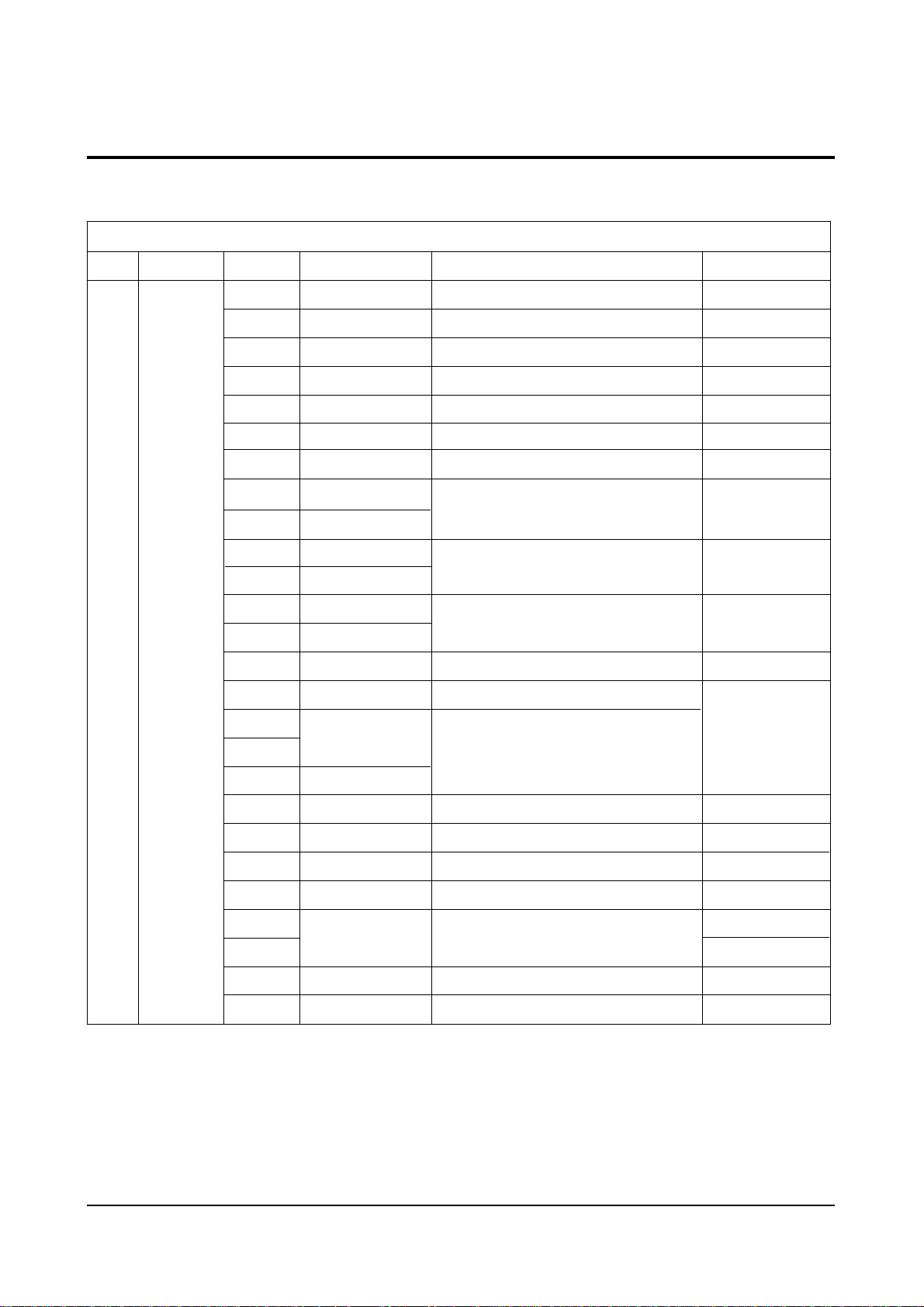
4-8-2 Deflection (Memory Data)
- SIM408A USA, LATIN FACTORY (VDP IC VDP3108B)
15" FLAT
H Bow
H SYMMETRY
H CORNER
PIP TINT
PIP H.POS
SIM-408A USA,LATIN FACTORY (VDP IC VDP3108B)
Model
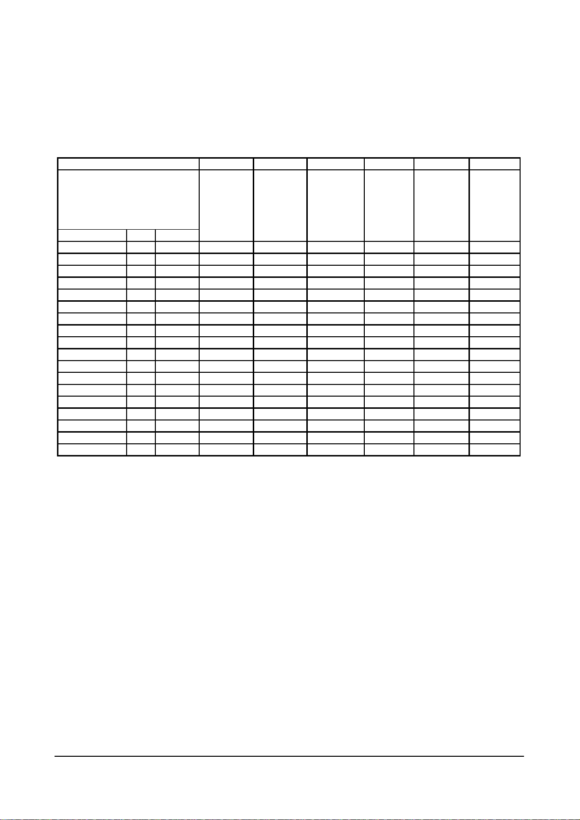
4-8-2(A) GEOMETRIC ADJUSTMENT VALUE
INCH
Model
DEFLECTION INIT
H Bow
H Angle 0 FIX 0 0 0 0 0 0
H Dscc 0 FIX 3 3 3 3 3 3
V SHIFT -40 Control -27 -24 -18 -18 -40 -35
V AMP 5 Control -50 -41 18 18 5 20
V SLOPE -2 Control -7 -4 -4 -4 -2 -4
V SC -7 FIX 0 -13 -13 -13 -13 -13
H EW 64 Control 10 -37 64(FIX) 64(FIX) 64(FIX) 64(FIX)
H TRAPEZIUM -20 Control -82 -48 -20(FIX) -20(FIX) -20(FIX) -20(FIX)
H PARABOLA -13 Control -89 -44 -13(FIX) -13(FIX) -13(FIX) -13(FIX)
H SYMMETRY
H CORNER
H SHIFT 4 Control 0 8 13 13 4 13
PIP CONTRAST FIX 0 0 0 0 0 0
PIP TINT
PIP PAL V.POS FIX 12 12 12 12 12 12
PIP NTSC V.POS FIX 12 12 12 12 12 12
PIP H.POS
0 FIX 0 0 0 0 0 0
13 FIX 13 13 13 13 13 13
15 Control 0 69 69(FIX) 69(FIX) 69(FIX) 69(FIX)
FIX 0 0 0 0 0 0
FIX 12 12 12 12 12 12
27V 1.3R 23V 1.3R 25V 1R 27V 1R 20V 1R 15" FLAT
TXK2767 CL25D4W
TXK2550
TXK2554
TXK2566
TXK2567
CL663BW
TXK2750
TXK2754
TXK2060
TXK2066
TXK2067
CT-15A8

Alignment and Adjustments
4-6 Samsung Electronics
4-8-2(B) SCREEN CHANGE (I2C BUS GEOMETRIC ADJUSTMENT)
1 V Shift
V Slope
2
3 H EW
6 V Amp
V SC
7
8
H Trapizium
4 H Parabola
5 H Corner
9
H Symmetry
10
H Shift

Alignment and Adjustments
Samsung Electronics 4-7
4-8-2(C) VIDEO ADJUST 1
27V 1.3R 23V 1.3R 25V 1R 27V 1R 20V 1R 15" FLAT
TXK2767 CL25D4W
TXK2550
TXK2554
TXK2566
TXK2567
CL663BW
TXK2750
TXK2754
TXK2060
TXK2066
TXK2067
CT-15A8
DEFLECTION INIT
H Bow
0FIX000000
H Angle 0FIX000000
H Dscc 0FIX333333
V SHIFT -40 Control -27 -2 4 -18 -18 - 4 0 -35
V AMP 5 Control -50 -41 1 8 18 5 20
V SLOPE -2 Control -7 -4 -4 -4 -2 -4
V SC -7 FIX 0 -13 -13 -13 -13 -13
H EW 64 Control 10 -37 64(FIX) 64(FIX) 64(FIX) 64(FIX)
H TRAPEZIUM -20 Control -82 -4 8 -20(FIX) -20(FIX) -20(FIX) -20(FIX)
H PARABOLA -1 3 Control -89 -44 -13(FIX) -13(FIX) -13(FIX) -13(FIX)
H SYMMETRY 13 FIX 13 13 13 13 13 13
H CORNER 1 5 Control 0 69 69(FIX) 69(FIX) 69(FIX) 69(FIX)
H SHIFT 4 Control 0 8 13 13 4 13
PIP CONTRAST FIX000000
PIP TINT FIX000000
PIP PAL V.POS FIX 12 12 12 12 12 12
PIP NTSC V.POS FIX 12 12 12 12 12 12
PIP H.POS FIX 12 12 12 12 12 12
25V 1R
20V 1R
INIT
SUB BRIGHT
SUB COLOR
SUB TINT
BCL THRESHOLD
SIM-408A USA,LATIN FACTORY (VDP IC VDP3108B)
Model
INCH
Model
Note 1. Beam Control Limit Characteristic
WDRGB
BCL THESHOLD
1.8mA
1.6mA
MIN
BCL GAIN
MAX
INCH
Model
VIDEO ADJUST1
RED CUT OFF 127 Control 127 127 127 127 127 127
GREEN CUT OFF 127 FIX 127 127 127 127 127 127
INIT
BLUE CUT OFF 127 Control 127 127 127 127 127 127
RED DRIVE 127 Control 150 127 127 127 127 127
GREEN DRIVE 127 FIX 127 127 127 127 127 127
BLUE DRIVE 127 Control 170 127 127 127 127 127
SUB BRIGHT
SUB CONTRAST 52 Control 52 52 52 52 52 52
SUB COLOR
SUB TINT
BCL THRESHOLD
BCLGAIN 8 FIX 8 8 8 8 8 8
BCL TIME 13 FIX 10 10 10 10 10 13
DVD SUB TINT 90 FIX 100 100 100 100 100 120
N. YC DELAY 0 FIX 3 3 3 3 3 4
110 Control 100 110 100 100 114 110
27 FIX 50 50 50 50 50 67
30 FIX 70 70 70 70 30 15
62 FIX 60 54 58 58 70 40
beam
27V 1.3R 23V 1.3R 25V 1R
TXK2550
TXK2554
TXK2767 CL25D4W
TXK2566
TXK2567
CL663BW
27V 1R 20V 1R
TXK2750
TXK2754
TXK2060
TXK2066
TXK2067
15" FLAT
CT-15A8
50
IRE
Alignment and Adjustments
4-8 Samsung Electronics
4-8-2(E) VIDEO 3 ADJUST
4-8-2(D) VIDEO 2 ADJUST
V SHIFT -40 Control -27 -24 - 1 8 -18 -40 -35
V AMP 5 Control -5 0 -41 18 18 5 20
V SLOPE -2 Control -7 -4 -4 -4 - 2 -4
V SC -7 FIX 0 -13 -13 -13 -13 -13
H EW 64 Control 10 - 3 7 64(FIX) 64(FIX) 64(FIX) 64(FIX)
H TRAPEZIUM -20 Control - 8 2 -48 -20(FIX) -20(FIX) -20(FIX) -20(FIX)
H PARABOLA -13 Control -89 -4 4 -13(FIX) -13(FIX) -13(FIX) -13(FIX)
H SYMMETRY 13 FIX 13 13 13 13 13 13
H CORNER 15 Control 0 69 69(FIX) 69(FIX) 69(FIX) 69(FIX)
H SHIFT 4 Control 0 8 13 13 4 13
PIP CONTRAST FIX000000
PIP TINT FIX000000
PIP PAL V.POS FIX 12 12 12 12 12 12
PIP NTSC V.POS FIX 12 12 12 12 12 12
PIP H.POS FIX 12 12 12 12 12 12
27V 1.3R 23V 1.3R 25V 1R
27V 1R 20V 1R 15" FLAT
TXK2767 CL25D4W
TXK2550
TXK2554
TXK2566
TXK2567
CL663BW
TXK2750
TXK2754
TXK2060
TXK2066
TXK2067
CT-15A8
VIDEO ADJUST1
INIT
RED CUT OFF 127 Control 127 127 127 127 127 127
GREEN CUT OFF 127 FIX 127 127 127 127 127 127
BLUE CUT OFF 1 2 7 Control 127 127 127 127 127 127
RED DRIVE 127 Control 1 5 0 127 127 127 127 127
GREEN DRIVE 127 FIX 127 127 127 127 127 127
BLUE DRIVE 127 Control 170 127 127 127 127 127
SUB BRIGHT 110 Control 100 110 100 100 114 110
SUB CONTRAST 52 Control 52 52 52 52 52 52
SUB COLOR 27 FIX 50 50 50 50 50 67
SUB TINT 30 FIX 70 70 70 70 30 15
BCL THRESHOLD 62 FIX 60 54 58 58 70 40
BCLGAIN 8 FIX 8 8 8 8 8 8
BCL TIME 13 FIX 10 10 10 10 10 13
DVD SUB TINT 90 FIX 100 100 100 100 100 120
N. YC DELAY 0 FIX 3 3 3 3 3 4
B STRETCH-BTHR
NTSC COMB FILTER
EHT TIME
DTI BAND
INCH
Model
25V 1R
27V 1R
20V 1R
15" FLAT
CT-15A8
PEAK WHITE LIMLT
SOFT LIMIT SLOPE B
HARD LIMIT
MODULATION ON/OFF
LIMIT VALUE
VELOCITY DELAY
INCH
Model
VIDEO ADJUST2 INIT
B STRETCH-BTHR
B DTRETCH-BTLT 8 FIX 8 8 8 8 8 8
B STERTCH-BAM 4 FIX 4 4 4 4 4 4
CORING 31 FIX 31 31 31 31 31 31
NTSC COMB FILTER
RGB BRIGHT 0 FIX 0 0 0 0 0 0
RG B CONTRAST 0 FIX 0 0 0 0 0 0
EHT TIME
EHT VERTICAL FIX 60 60 60 60 60 60
DTI CORING FIX 0 0 0 0 0 0
DTI GAIN FIX 1 1 1 1 1 1
DTI BAND
EHT OFFSET FIX 0 0 0 0 0 0
EHT HORIZONTAL FIX 0 0 0 0 0 0
50 FIX 50 50 50 50 50 50
1 FIX 1 1 1 1 1 1
0 FIX 0 0 0 0 0 0
FIX 1 1 1 1 1 1
27V 1.3R 23V 1.3R 25V 1R 27V 1R 20V 1R 15" FLAT
TXK2767
CL25D4W
TXK2550
TXK2554
TXK2566
TXK2567
CL663BW
TXK2750
TXK2754
TXK2060
TXK2066
TXK2067
INCH
Model
VIDEO ADJUST3 INIT
PEAK WHITE LIMLT
SOFT LIMIT SLOPE B
HARD LIMIT
MODULATION ON/OFF
A TILT POINT 0 FIX
B TILT POINT 0 FIX
GAIN 1 (VIDEO) FIX
DELAY 1 (VIDEO) FIX
PEAK VIDEO REF FIX
PEAK VIDEO GAIN FIX
LIMIT VALUE
VELOCITY DELAY
VELOCITY CORING FIX
ACC-REF 20 FIX
ACCR 21 FIX
255 FIX
255 FIX
4 FIX
0 FIX
FIX
FIX
27V 1.3R 23V 1.3R 25V 1R
TXK2550
TXK2767 CL25D4W
255 255 255 255 255 255
4 4 4 4 4 4
255 255 255 255 255 255
0 0 0 0 0 0
0 0 0 0 0 0
114 114 114 114 114 114
11 11 11 11 11 11
3 3 3 3 3 3
0 0 0 0 0 0
0 0 0 0 0 0
74 74 74 74 74 74
7 7 7 7 7 7
10 10 10 10 10 10
20 20 20 20 20 20
21 21 21 21 21 21
TXK2554
TXK2566
TXK2567
CL663BW
27V 1R
TXK2750
TXK2754
20V 1R
TXK2060
TXK2066
TXK2067
15" FLAT
CT-15A8
CT-15A8

Alignment and Adjustments
Samsung Electronics 4-9
“Soft Limit” is that Limitting
the peak white without
feed-back, but “Peak Limit” is
that with feed-back for white
peak level
Note 2. Soft Limit & Hard Limit Characteristics
✐
4-8-2(F) OTHERS
27V 1.3R 23V 1.3R 25V 1R 27V 1R 20V 1R 15" FLAT
TXK2767 CL25D4W
TXK2550
TXK2554
TXK2566
TXK2567
CL663BW
TXK2750
TXK2754
TXK2060
TXK2066
TXK2067
CT-15A8
INIT
255 FIX
255 255 255 255 255 255
4 FIX
444444
255 FIX
255 255 255 255 255 255
0 FIX
000000
0 FIX
000000
0 FIX
114 114 114 114 114 114
FIX
11 11 11 11 11 11
FIX
333333
FIX
000000
FIX
000000
FIX
74 74 74 74 74 74
FIX
777777
FIX
10 10 10 10 10 10
20 FIX
20 20 20 20 20 20
21 FIX
21 21 21 21 21 21
INCH
Model
4-8-2(G) G2 ADJUST
TXK2567
CL663BW
TXK2754
TXK2067
INIT
255 FIX
255 255 255 255 255 255
4 FIX
444444
255 FIX
255 255 255 255 255 255
0 FIX
000000
0 FIX
000000
0 FIX
114 114 114 114 114 114
FIX
11 11 11 11 11 11
FIX
333333
FIX
000000
FIX
000000
FIX
74 74 74 74 74 74
FIX
777777
FIX
10 10 10 10 10 10
20 FIX
20 20 20 20 20 20
21 FIX
21 21 21 21 21 21
27V 1.3R
23V 1.3R
25V 1R 27V 1R 20V 1R 15" FLAT
TXK2767
CL25D4W
TXK2550
TXK2554
TXK2566
TXK2567
CL663BW
TXK2750
TXK2754
TXK2060
TXK2066
TXK2067
CT-15A8
H Control 275/295 35FL 275/295 35FL 275/295 35FL 275/295 35FL 275/295 35FL 275/295 95FL
L Control 275/295 1.2FL 275/295 1.2FL 275/295 1.2FL 275/295 1.2FL 275/295 1.2FL 275/295 2.0FL
15" FLAT
MRC R G B
INCH
Model
INIT
Output
511
400
300
200
100
0
0
Part 1 Part 2
tilt 1 [0...511]
100 200 300 400 500 600 700 800 900 1023
Slope 1 [0...15]
0
2
4
6
8
10
12
14
tilt 2 [0...511]
0
2
4
6
8
10
12
14
Slope 2 [0...15]
Hard limiter
range=256...511
Li
Soft Limit Slope B
OTHERS
VSU 108 FIX 108 104 100 100 104 110
VSU2 FIX 0 0 0 0 0 0
H QEW 0 FIX 0 0 0 0 0 0
H ZOOM Parabola 8 FIX -22 -35 8 8 8 8
H 16:9 Parabola -10 FIX 8 13 -18 -18 -18 -10
TTX H Shift 0 FIX 0 0 0 0 0 0
PAL V SHIFT FIX OFFSET OFFSET OFFSET OFFSET OFFSET OFFSET
INCH
Model
INIT
27V 1.3R
TXK2767
23V 1.3R
CL25D4W
25V 1R 27V 1R 20V 1R 15" FLAT
TXK2550
TXK2554
TXK2566
TXK2567
CL663BW
PAL H SHIFT FIX OFFSET OFFSET OFFSET OFFSET OFFSET OFFSET
Melidy Volume 5 FIX 7 7 7 7 7 7
WHITE BALANCE
H Control 275/295 35FL 275/295 35FL 275/295 35FL 275/295 35FL 275/295 35FL 275/295 95FL
L Control 275/295 1.2FL 275/295 1.2FL 275/295 1.2FL 275/295 1.2FL 275/295 1.2FL 275/295 2.0FL
TXK2750
TXK2754
TXK2060
TXK2066
TXK2067
CT-15A8
MRC R G B
MRWDG 110
IBRM FIX 210
WDRV FIX 35
CDL FIX 170
COL MIN 150
INCH
Model
G2 Adjust
27V 1.3R
TXK2767
Max 110
23V 1.3R
CL25D4W
110
110
205
35
120
140
25V 1R 27V 1R 20V 1R 15" FLAT
TXK2550
TXK2554
TXK2566
TXK2567
CL663BW
TXK2750
TXK2754
TXK2060
TXK2066
TXK2067
CT-15A8
110 110 110 110
110 110 110 110
210 210 205 220
35 35 35 35
150 150 115 180
150 150 120 100
Alignment and Adjustments
4-10 Samsung Electronics
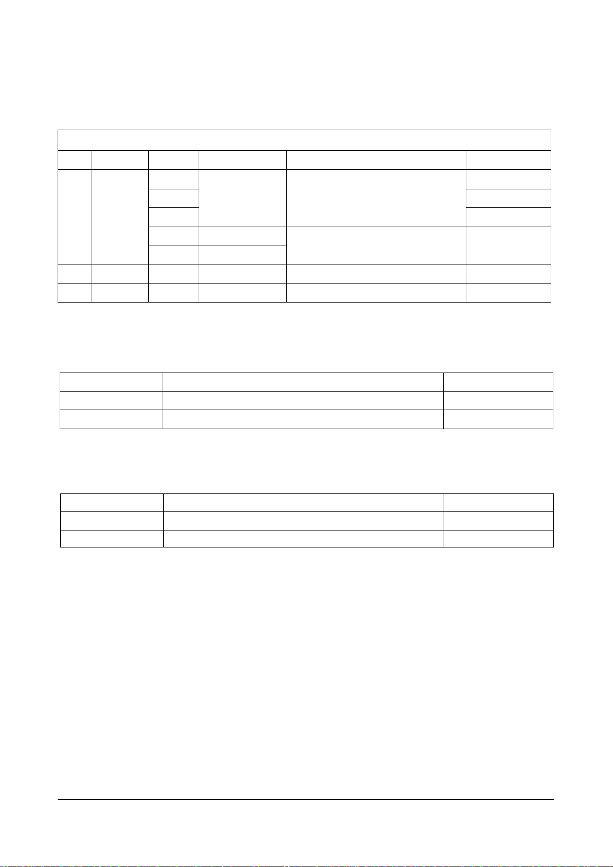
4-8-3 Deflection (Memory Data)
- SIM408A USA, LATIN FACTORY (VDP IC VDP3130Y)
15" FLAT
21" FLAT
25" FLAT
CL15A8
CL21A8
DEFLECTION
INIT
H Bow
H Angle
H Dscc
V SHIFT
V AMP
V SLOPE
H E
H TRAPEZIUM
-20(FIX)
H PARABOLA
-13(FIX)
H SYMMETRY
H CORNER
H SHIFT
PIP CONTRAST
PIP TINT
PIP PAL V.POS
PIP NTSC V.POS
PIP H.POS
SIM-408A USA,LATIN FACTORY (VDP IC VDP3130Y)
INCH
MODEL
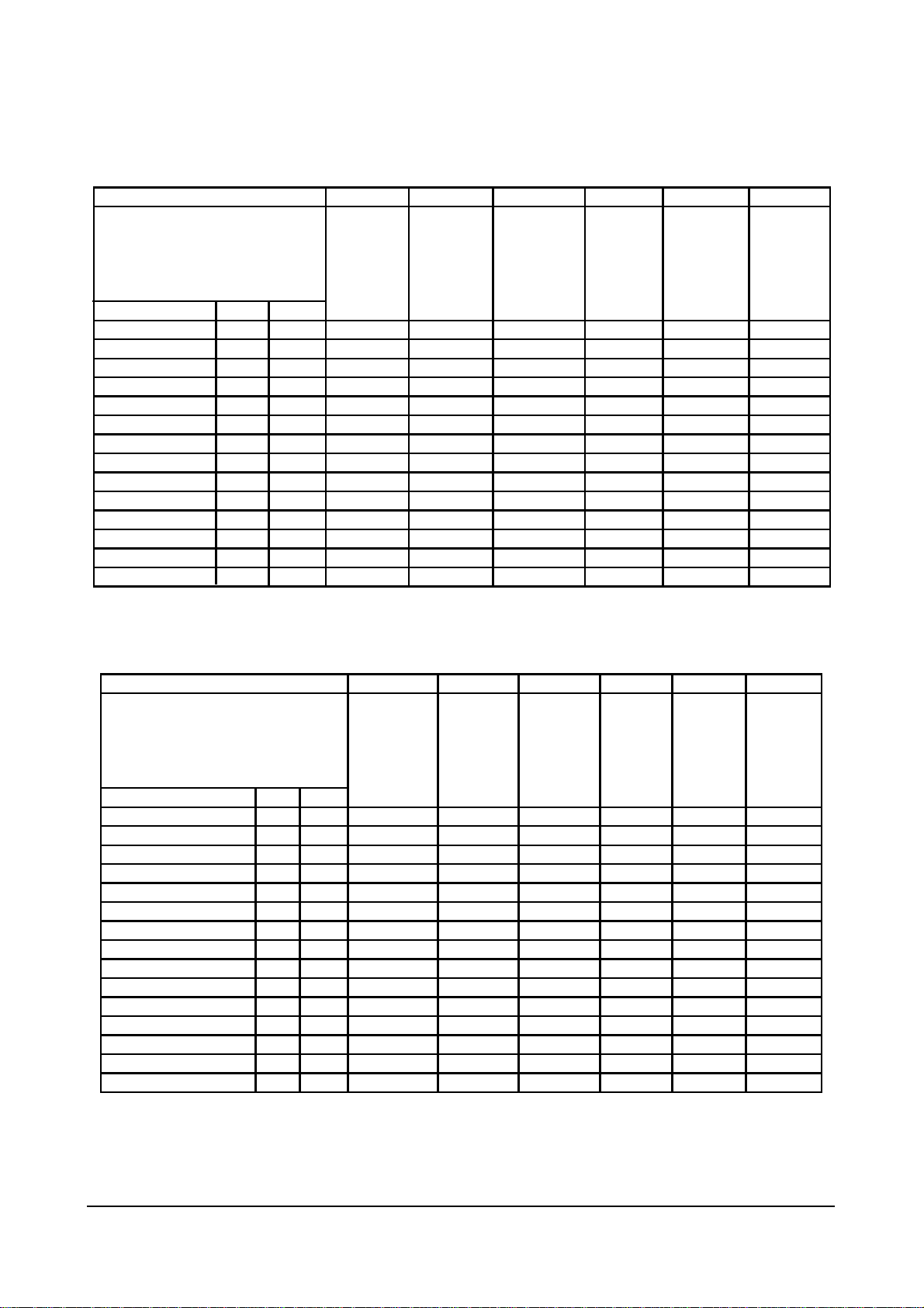
4-8-3(A) GEOMETRIC ADJUSTMENT VALUE
27V 1.3R 15" FLAT 21" FLAT 25" FLAT
TXK2768 CL15A8 CL21A8 CL25A6
DEFLECTION
INIT
H Bow FIX 0 0 0 0
H Angle FIX 0 0 0 0
H Dscc FIX 3 2 2 3
V SHIFT -40 Control -27 -35 -27 -50
V AMP 5 Control -50 20 6 -15
V SLOPE -2 Control -7 -4 -6 -2
V SC -7 FIX -6 -6 -6 -6
H E W 64 Control 10 64(FIX) 43 10
H TRAPEZIUM -20 Control -82 -20(FIX) -20 -20
H PARABOLA -13 Control -89 -13(FIX) -29 -60
H SYMMETRY 13 FIX 13 13 13 13
H CORNER 15 Control 0 69(FIX) 69 69
H SHIFT 4 Control 0 13 -24 -27
PIP CONTRAST FIX 10 0 0 0
PIP TINT FIX 63 0 0 0
PIP PAL V.POS FIX 12 12 12 12
PIP NTSC V.POS FIX 12 12 12 12
PIP H.POS FIX 12 12 12 12
15" FLAT
21" FLAT
25" FLAT
CL21A8
CL25A6
VIDEO ADJUST1
INIT
RED CUT OFF
GREEN CUT OFF
BLUE CUT OFF
RED DRIVE
GREEN DRIVE
BLUE DRIVE
SUB BRIGHT
SUB CONTRAST
SUB COLOR
SUB TINT
BCL THRESHOLD
BCLGAIN
BCL TIME
DVD SUB TINT
N. YC DELAY
SIM-408A USA,LATIN FACTORY (VDP IC VDP3130Y)
INCH
Model
INCH
MODEL
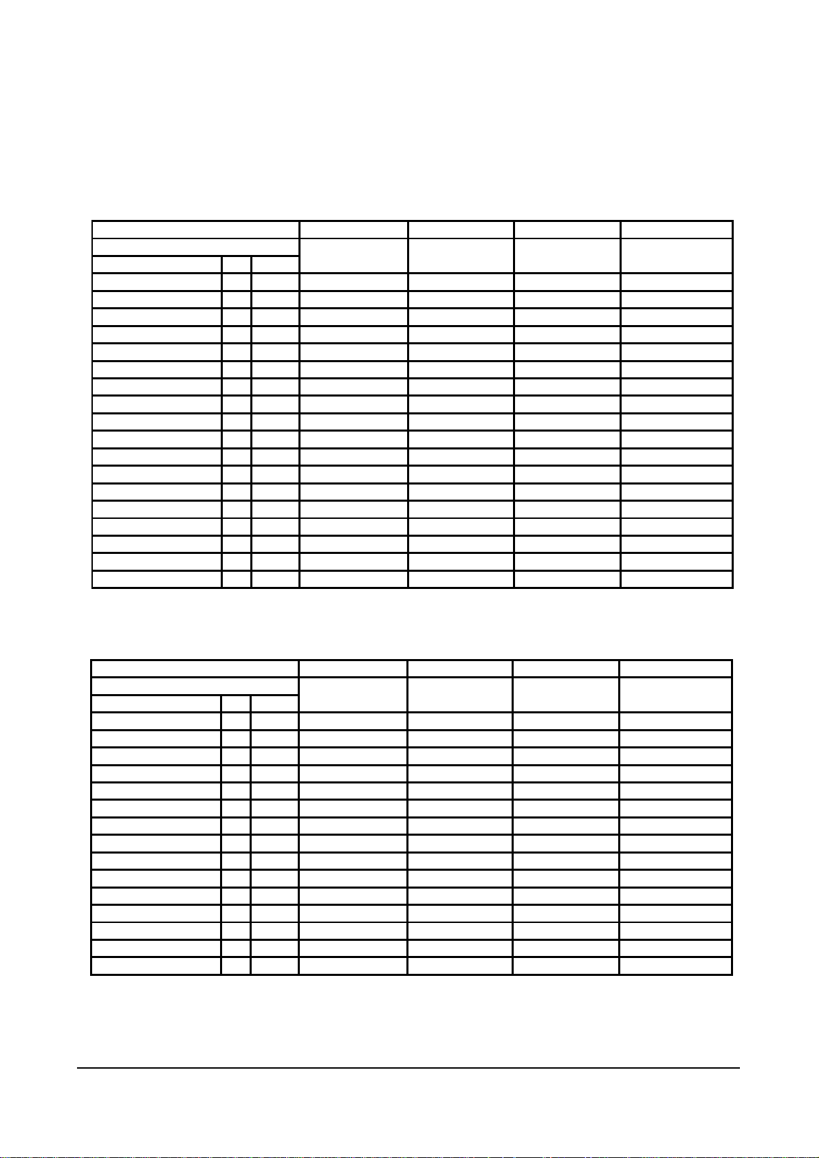
4-8-3(B) VIDEO ADJUST 1
DEFLECTION
H Bow
H Angle
H Dscc
V SHIFT
V AMP
V SLOPE
V SC -7 FIX -6 -6 -6 -6
H E
W 64 Control 10 64(FIX) 43 10
H TRAPEZIUM
H PARABOLA
H SYMMETRY
H CORNER
H SHIFT
PIP CONTRAST
PIP TINT
PIP PAL V.POS
PIP NTSC V.POS
PIP H.POS
INCH
MODEL
INIT
FIX 0 0 0 0
FIX 0 0 0 0
FIX 3 2 2 3
-40 Control -27 -35 -27 -50
5 Control -50 20 6 -15
-2 Control -7 -4 -6 -2
27V 1.3R 15" FLAT
TXK2768 CL15A8
21" FLAT
CL21A8
-20 Control -82 -20(FIX)
-13 Control -89 -13(FIX)
13 FIX 13 13 13 13
15 Control 0 69(FIX) 69 69
4 Control 0 13 -24 -27
FIX 10 0 0 0
FIX 63 0 0 0
FIX 12 12 12 12
FIX 12 12 12 12
FIX 12 12 12 12
-20 -20
-29 -60
VIDEO ADJUST1
RED CUT OFF
GREEN CUT OFF
BLUE CUT OFF
RED DRIVE
GREEN DRIVE
BLUE DRIVE
SUB BRIGHT
SUB CONTRAST
SUB COLOR
SUB TINT
BCL THRESHOLD
BCLGAIN
BCL TIME
DVD SUB TINT
N. YC DELAY
INCH
Model
INIT
127 Control 127 127 127 127
127 FIX 127 127 127 127
127 Control 127 127 127 127
127 Control 127 127 127 127
127 FIX 127 127 127 127
127 Control 170 127 127 127
110 Control 100 110 110 110
52 Control 52 52 52 52
27 FIX 50 67 87 87
30 FIX 70 15 30 30
62 FIX 60 40 62 60
8 FIX 9 9 9 9
13 FIX 55 5 5
90 FIX 25 25 25 25
0 FIX 3 4 4 4
27V 1.3R 15" FLAT
TXK2768 CL15A8 CL21A8
21" FLAT
25" FLAT
CL25A6
25" FLAT
CL25A6

Alignment and Adjustments
Samsung Electronics 4-11
4-8-2(C) VIDEO 2 ADJUST
15" FLAT
21" FLAT
25" FLAT
CL15A8
CL21A8
VIDEO ADJUST2
INIT
B STRETCH-BTHR
B DTRETCH-BTLT
B STERTCH-BAM
CORING
NTSC COMB FILTER
RGB BRIGHT
RG B CONTRAST
EHT TIME
EHT VERTICAL
DTI CORING
DTI GAIN
DTI BAND
EHT OFFSET
EHT HORIZONTAL
INCH
Model
4-8-2(D) VIDEO 3 ADJUST
27V 1.3R 15" FLAT 21" FLAT 25" FLAT
TXK2768 CL15A8 CL21A8 CL25A6
VIDEO ADJUST2
INIT
B STRETCH-BTHR 50 FIX 50 50 50 50
B DTRETCH-BTLT 8 FIX 8 8 8 8
B STERTCH-BAM 4 FIX 4 4 4 4
CORING 31 FIX 31 31 31 31
NTSC COMB FILTER 1 FIX 3 3 3 3
RGB BRIGHT 0 FIX 0 0 0 0
RG B CONTRAST 0 FIX 0 0 0 0
EHT TIME 0 FIX 8 8 8 8
EHT VERTICAL 60 FIX 60 60 60 60
DTI CORING 0 FIX 0 0 0 0
DTI GAIN 1 FIX 1 1 1 1
DTI BAND 1 FIX 1 1 1 1
EHT OFFSET 0 FIX 0 0 0 0
EHT HORIZONTAL 0 FIX 0 0 0 0
15" FLAT
21" FLAT
25" FLAT
CL15A8
CL21A8
CL25A6
VIDEO ADJUST3
INIT
PEAK
WHITE LIMLT
SOFT LIMIT SLOPE B
HARD LIMIT
MODULATION ON/OFF
A TILT POINT
B TILT POINT
GAIN 1 (VIDEO)
DELAY 1 (VIDEO)
PEAK VIDEO REF
PEAK VIDEO GAIN
LIMIT VALUE
VELOCITY DELAY
VELOCITY CORING
INCH
Model
INCH
Model
VIDEO ADJUST2
B STRETCH-BTHR
B DTRETCH-BTLT
B STERTCH-BAM
CORING
NTSC COMB FILTER
RGB BRIGHT
RG B CONTRAST
EHT TIME
EHT VERTICAL
DTI CORING
DTI GAIN
DTI BAND
EHT OFFSET
EHT HORIZONTAL
INCH
Model
27V 1.3R 15" FLAT
INIT
50 FIX 50 50 50 50
8 FIX 8 8 8 8
4 FIX 4 4 4 4
31 FIX 31 31 31 31
1 FIX 3 3 3 3
0 FIX 0 0 0 0
0 FIX 0 0 0 0
0 FIX 8 8 8 8
60 FIX 60 60 60 60
0 FIX 0 0 0 0
1 FIX 1 1 1 1
1 FIX 1 1 1 1
0 FIX 0 0 0 0
0 FIX 0 0 0 0
TXK2768 CL15A8
21" FLAT
CL21A8
VIDEO ADJUST3
PEAK
WHITE LIMLT
SOFT LIMIT SLOPE B
HARD LIMIT
MODULATION ON/OFF
A TILT POINT
B TILT POINT
GAIN 1 (VIDEO)
DELAY 1 (VIDEO)
PEAK VIDEO REF
PEAK VIDEO GAIN
LIMIT VALUE
VELOCITY DELAY
VELOCITY CORING
ACC-REF 20 FIX 20 20 20 20
ACCR 21 FIX 21 21 21 21
INCH
Model
27V 1.3R 15" FLAT
INIT
255 FIX 255 255 255 255
4 FIX 4 4 4 4
255 FIX 255 255 255 255
0 FIX 0 0 0 0
0 FIX 0 0 0 0
0 FIX 114 114 114 114
11 FIX 11 11 11 11
3 FIX 3 3 3 3
0 FIX 0 0 0 0
0 FIX 0 0 0 0
127 FIX 127 74 74 74
7 FIX 7 7 7 7
2 FIX 2 10 10 10
TXK2768 CL15A8
21" FLAT
CL21A8
25" FLAT
CL25A6
25" FLAT
CL25A6
 Loading...