

Page 1

4-1
Alignment and Adjustments
Samsung Electronics
4. Alignment and Adjustments
4-1 Preadjustment
4-1-1 Factory Mode
1. Do not attempt these adjustments in the Video
Mode.
2. The Factory Mode adjustments are necessary
when either the EEPROM (IC902) or the CRT is
replaced.
3. Do not tamper with the "Adjustment" screen of
the Factory Mode menu. This screen is
intended only for factory use.
4-1-2 When EEPROM (IC902) Is Replaced
1. When IC902 is replaced all adjustment data
revert to initial values. It is necessary to reprogram this data.
2. After IC902 is replaced, warm up the TV for 10
seconds
4-1-3 When CRT Is Replaced
1. Make the following adjustments AFTER
setting up after setting up purity and
convergence:
White Balance
Sub-Brightness
Vertical Center
Vertical Size
Horizontal Size
Fail Safe (This adjustment must be the last
step.)
2. If the EEPROM or CRT is replaced, set PSL
and PVA to 15 and 63 (Factory Mode).
4-2 Factory/Service Mode
4-2-1 Procedure for the "Adjustment" Mode
1. This mode uses the standard remote control.
The Service Mode is activated (1) by pressing
the (Display → (FACTORY) service key or (2)
by entering the following remote-control
sequence:
STAND-BY→DISPLAY→ P-STD → MUTE →
POWER ON
2. The "SERVICE (FACTORY)" message will be
displayed. The Service Mode has four
components: Adjustment, Test Pattern, Option
Bytes and Reset.
3. Access the Adjustment Mode by pressing the
"VOLUME" keys ( Up or Down). The
adjustment parameters are listed in the
accompanying table. Select them by pressing
the CHANNEL keys (▲,▼).
4. Selection sequences for the PAL system:
DOWN or UP key:
VCO>SBT>SCT>SCR>SC>RG>CDL>STT>LCO
>LA>PSL>PVS>PVA>PHS>PEW>PEP>PEC>P
ET>LSC>TSC>SA>NSL>NVS>NVA>NHS>NE
W>NEP>NEC>NET
5. Selection sequences for the NTSC system:
DOWN or UP key:
NVS>NVA>NSL>NHS>NEW>NEP>NEC>NET
6. The VOLUME keys increase or decrease the
adjustment values, (stored in the
non-volatile memory when Adjustment Mode
is cancelled).
7. Cancel the Adjustment Mode by re-pressing the
"Factory" or "Power on" keys.
Page 2
Alignment and Adjustments
4-2 Samsung Electronics
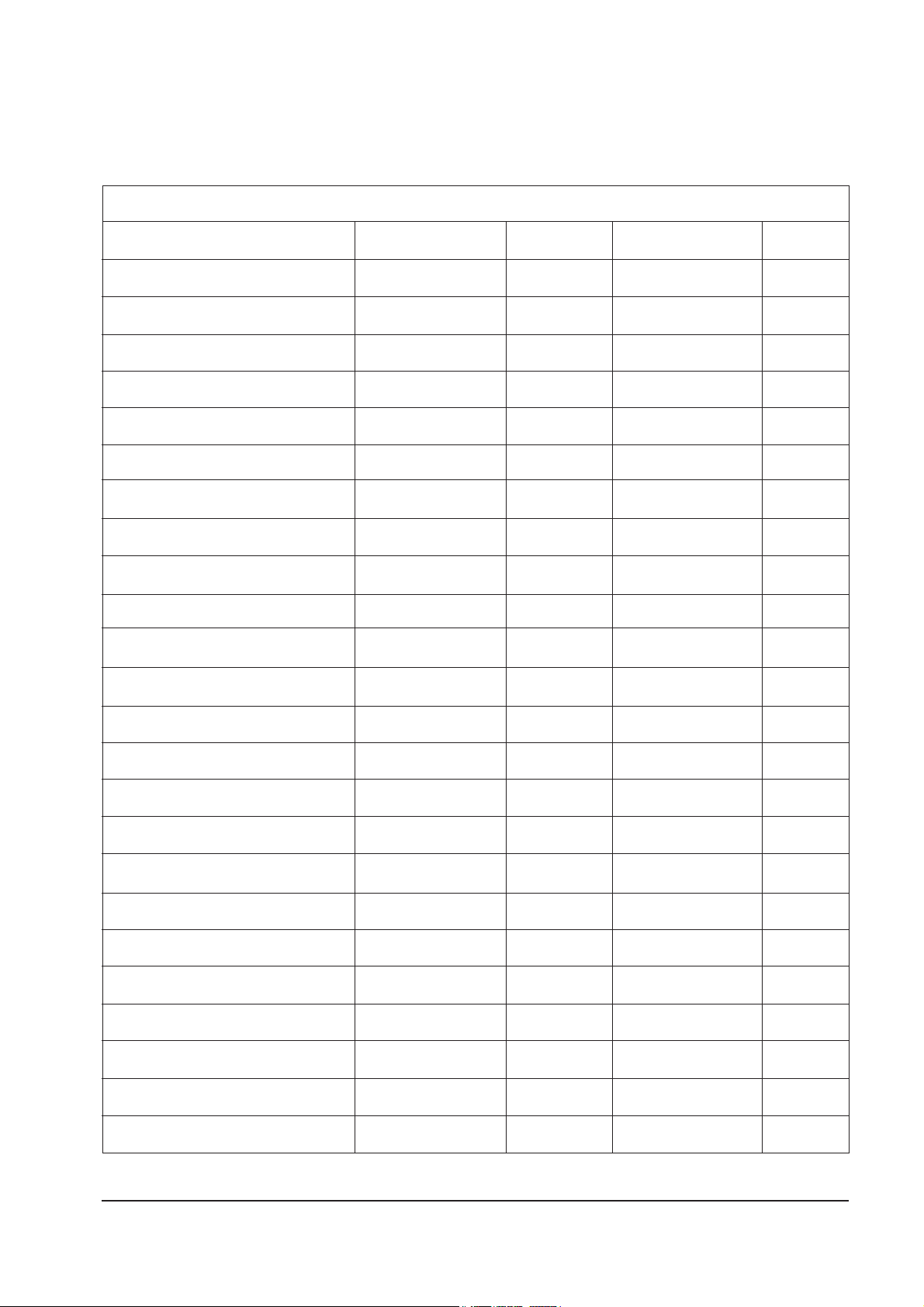
ADJUSTMENT DATA
15
60 ~ 75
6 ~ 10
7
15 FIXED
11 FIXED
25 ~ 45
25 ~ 45
-
0 ~ 10
63 FIXED
5
20 ~ 25
25 ~ 35
35
35 ~ 45
35 ~ 45
0 ~ 10
15 ~ 30
15 ~30
31 FIXED
10 ~ 30
25
25 FIXED
RANGE
0 ~ 63 STEP
0 ~ 127 STEP
0 ~ 23 STEP
0 ~ 23 STEP
0 ~ 23 STEP
0 ~ 63 STEP
0 ~ 7 STEP
0 ~ 127 STEP
0 ~ 9 STEP
0 ~ 63 STEP
0 ~ 63 STEP
0 ~ 63 STEP
0 ~ 63 STEP
0 ~ 63 STEP
0 ~ 63 STEP
0 ~ 63 STEP
0 ~ 63 STEP
0 ~ 63 STEP
0 ~ 63 STEP
0 ~ 63 STEP
0 ~ 63 STEP
0 ~ 63 STEP
0 ~ 49 STEP
0 ~ 63 STEP
INITIAL
15
63
7
7
15
11
31
31
4
5
63
5
25
31
31
40
38
22
22
30
25
15
25
25
OSD ABBREVIATION
AGC
VCO
SBT
SCT
SCR
SC
RG
BG
CDL
STT
LCO
LA
PSL
PVS
PVA
PHS
PEW
PEP
PEC
PET
VSC
TSC
SA
NSL
FUNCTION
AUTO GAIN CONTROL
VOLTAGE CONTROLLED OSCILLATOR
SUB BRIGHT
SUB CONTRAST
SUB COLOR
S-CORRECTION
RED DRIVE (GAIN)
BLUE DRIVE (GAIN)
CATHODE DRIVE LEVEL
SUB TINT
SECAM-L CONTROLLED OSCILLATOR
SOUND LEVEL ADJUSTMENT
PAL VERTICAL SLOPE
PAL VERTICAL SHIFT
PAL VERTICAL AMPLITUDE
PAL HORIZONTAL SHIFT
PAL EW-WIDTH
PAL EW-PARABOLA
PAL EW CORNER PARABOLA
PAL EW-TRAPEZIUM
VERTICAL SCROLL
TTX SUB CONTRAST
SEPARATION ADJUSTMENT
NTSC VERTICAL SLOPE
Table 4-1 Main Adjustment Parameter (Zilog µ-com)
4-2-2 Main Adjustment Parameter
Page 3
4-3
Alignment and Adjustments
Samsung Electronics
NOTE : PVS,PVA, PHS, NVS, NVA,NHS parameters must be aligned using both the
50Hz and 60Hz vertical-field rates.
4-2-3 Test Pattern
1. This mode can be used during servicing, or for confirming that
the convergence and purity adjustments are correct.
2. Access the Test Pattern parameters by pressing a CHANNEL
keys (▲,▼) while the Service Mode is on. The cursor will move
to the test pattern. Press the VOLUME keys. On-screen display:
■ RED
■ GREEN
■ BLUE
3. AGING Mode (Reference Only)
This pattern is used for pre-heating the CRT during
manufacturing--it is accessed in the factory by twice pressing the
"HIDDEN" key .
Even if the TV power is cut off, the Aging Mode is not cancelled,
The patterns are displayed at 5 sec intervals. The AGING mode
is cancelled by repressing the "HIDDEN" key.
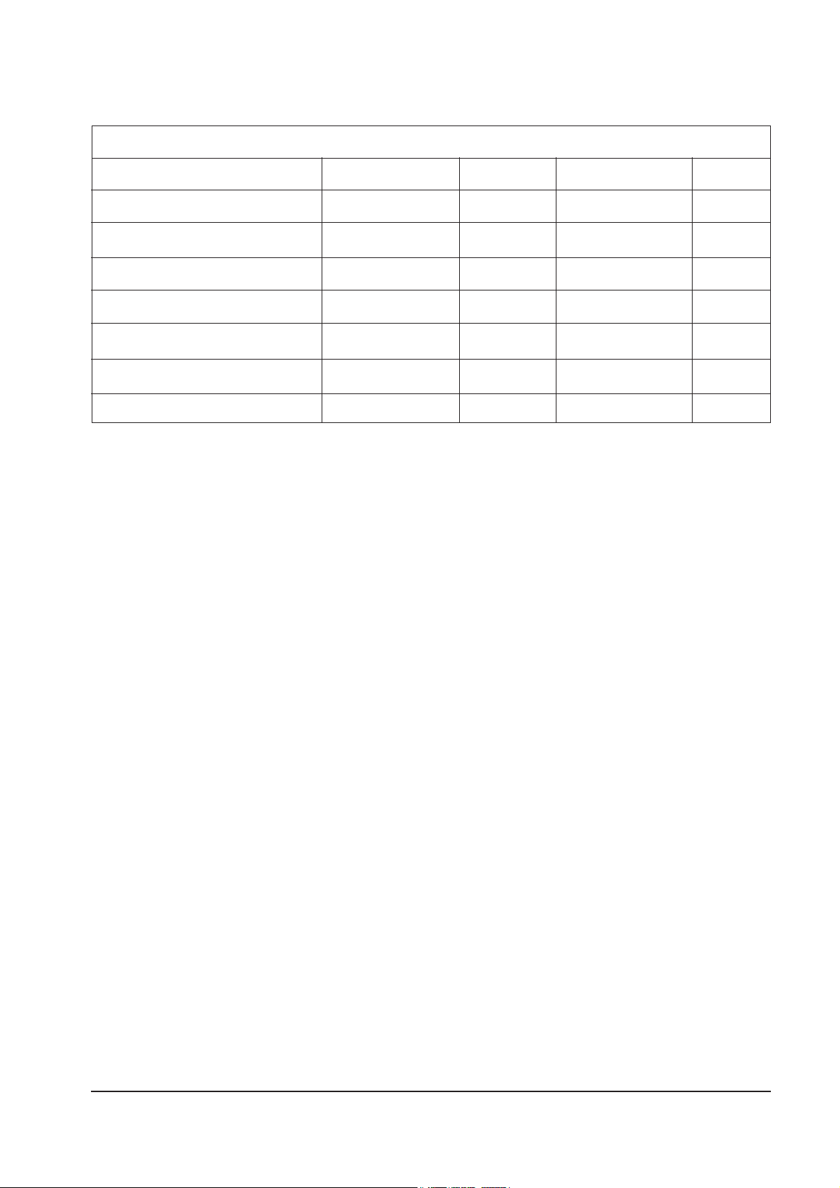
ADJUSTMENT DATARANGE INITIALOSD ABBREVIATIONFUNCTION
35 ~ 45
25 ~ 35
35 ~ 50
35 ~ 45
15 ~ 30
0 ~ 63 STEP
0 ~ 63 STEP
0 ~ 63 STEP
0 ~ 127 STEP
0 ~ 63 STEP
44
28
45
37
21
20
30
NVS
NVA
NHS
NEW
NEP
NEC
NET
NTSC VERTICAL SHIFT
NTSC VERTICAL AMPLITUDE
NTSC HORIZONTAL SHIFT
NTSC EW-WIDTH
NTSC EW PARABOLA
NTSC EW-CORNER PARABOLA
NTSC EW-TRAPEZIUM
Table 4-1 Main Adjustment Parameter (Zilog µ-com)(Continued)
Page 4
Alignment and Adjustments
4-4 Samsung Electronics
REMARKHIGHLOW
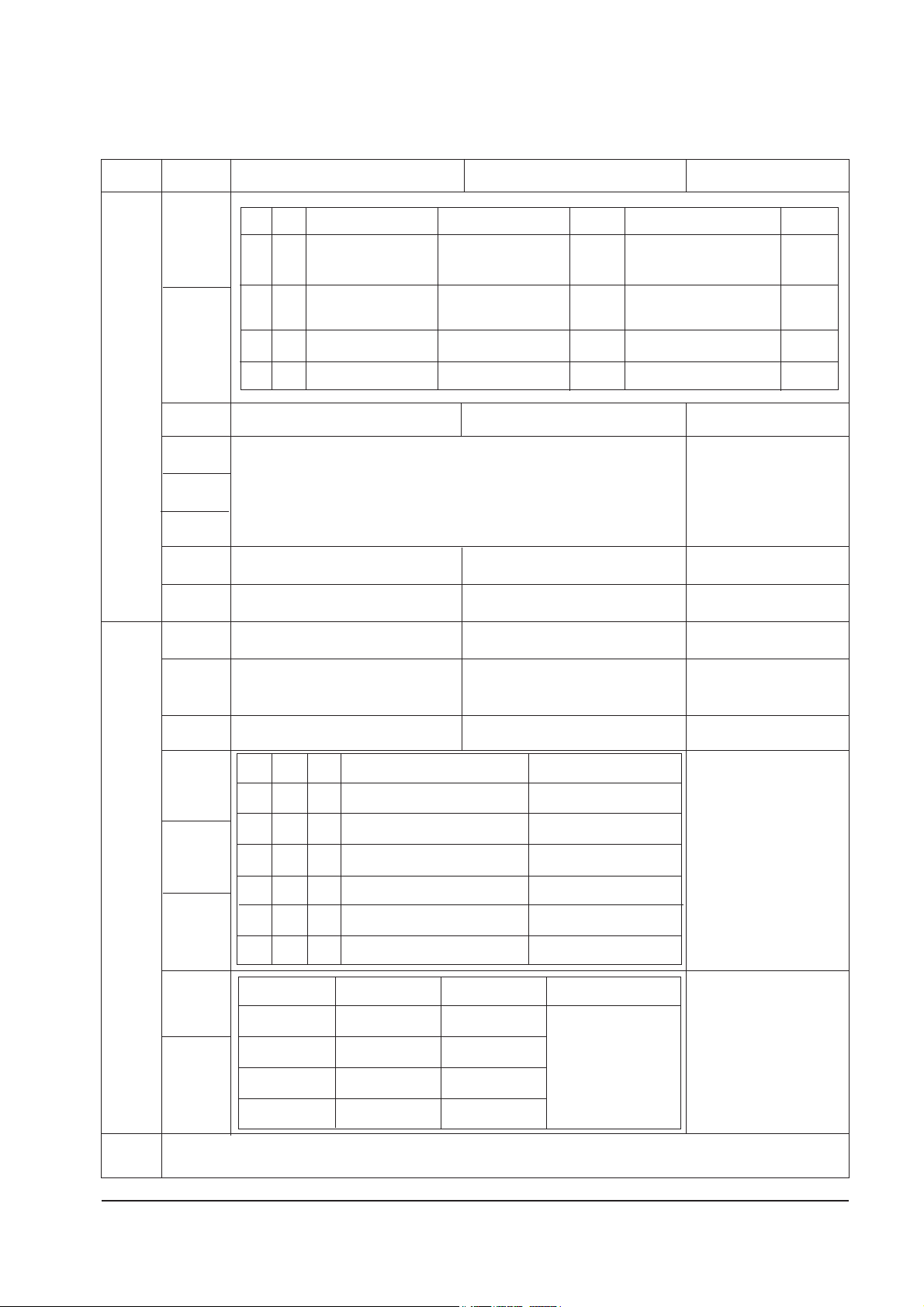
4-2-4 MICOM Option Byte Table
BIT
D7
D6
D5
D4
D3
D2
D1
D0
D7
D6
D5
D4
D3
D2
D1
D0
Last Status
TABLE 1
FOR MIDDLE EAST
■NORMAL MODE E/W
DATA=PLUS + 9
■ PLUS MODE PHS DATA=
PLUS - 1 (PAL/NT)
1) SOUND SYSTEM DURING
THE AUTO SEARCH
2) SOUND SYSTEM DURING
THE FACTORY MODE RESET
3) MANUAL SEARCH
(SYSTEM DOES NOT
MATTER)
Auto On
WITHOUT CHILD LOCK
TTX (ATS=OFF)
WITH PIP
NOISE REDUCTION ON/OFF
FUNCTION MENU DISPLAY (TDA8844)
RCA : NOT CH UP/DOWN FUNCTIONED
WITH CHILD LOCK
NO TTX (ATS = ON)
WITHOUT PIP
NOISE REDUCTION OFF(ALWAYS)
→OSD
NO DISPLAY (TDA8842)
SCART : CH UP/DOWN FUNCTIONED
B
Y
T
E
0
BYTE
B
Y
T
E
1
Middle East / Arab
English/Arabian
English/Arabian/French
English/French
English Only
South East / Asia
English/Thai
English/Vietnamese
English/Malay
English/Malay/Indonesian
Western/Eastern
English/German/French/
Spanish/Italian/Swedish/Dutch
English/Hungarian/Polish/
Rumanian/Czech/Croatian
English/French
English
TV
PLUS
→NORMAL
PLUS
→NORMAL→ZOOM→16:9
NORMAL
→ZOOM→16:9
NORMAL
→ZOOM→16:9
NORMAL
→ZOOM
PLUS
→NORMAL→ZOOM
D4
0
0
0
0
1
1
D3
0
0
1
1
0
0
D2
0
1
0
1
0
1
D7
0
0
1
1
D6
0
1
0
1
AV
PLUS
→NORMAL
PLUS
→NORMAL→ZOOM
NORMAL
→ZOOM→16:9
NORMAL
→ZOOM
NORMAL
→ZOOM
PLUS
→NORMAL→ZOOM
SYSTEM
B/G
D/K
I
B/G & D/K & M
D1
0
0
1
1
D0
0
1
0
1
REMARK
"MEMORY" BY
PROGRAM
CHANNELS
REQUIRED
CIS
-
English/
Russian
-
English
China
English/
Chinese
-
English
-
SYSTEM
OTHER
1) HIGH FOR XA/XB (ALWAYS) : CRYSTAL 3.58MHz/4.43MHz CONSTANT
2) AUDIO MUTE DURING NO SIGNAL (ALWAYS) 3) SET THE CONTRAST TO 90 IN THE STANDARD PICTURE
Page 5
4-5
Alignment and Adjustments
Samsung Electronics
REMARKHIGHLOW
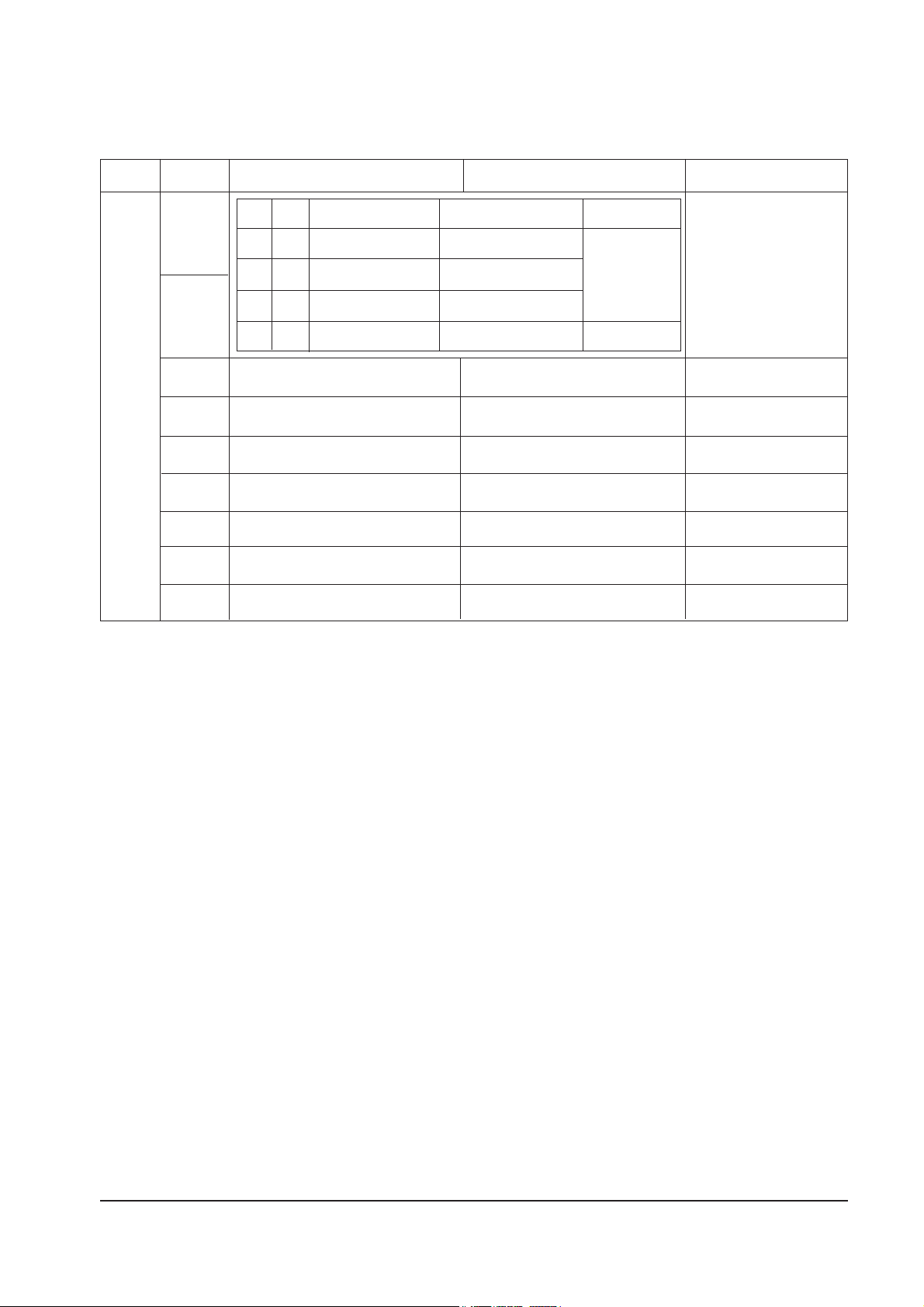
4-2-4 MICOM Option Byte Table
BIT
D7
D6
D5
D4
D3
D2
D1
D0
D0
FOR EUROPE CIS
INDIA ONLY
SZM-199EV ONLY
WITH TDA9178
NICAM ERROR CHECK BIT
AFT - OFF
TDA8844
RF AUDIO OUT MUTE ON
D/K STEREO F = 6.25'
CLOCK DISPLAY ON
WITHOUT TDA9178
-
AFT-ON
TDA8375
RF AUDIO OUT MUTE OFF
D/K STEREO F = 6.752
CLOCK DISPLAY OFF
B
Y
T
E
0
BYTE
SYSTEM
STEREO + NICAM
STEREO
LINE STEREO
MONO
D7
0
0
1
1
D6
0
1
0
1
IC
TDA9859 /TDA9874
TDA9859 / TDA9840
TDA9859
TDA8844
A/V
SCART
+ FRONT RCA
1 SCART/RCA
Page 6

4-2-6 RESET
The Reset Mode is used during factory inspection.
Function Reset:
1. Channels Add/Erase
2. Sort Non
3. Language Basic (English)
4. System Auto (Non-TTX micom only)
Alignment and Adjustments
4-6 Samsung Electronics
4-2-5 TABLE 1 (SYSTEM)
SYSTEM
CI
CII
CW
CF
CK/CX
CB
CS 1
CS 2
D4
1
1
1
1
0
0
0
0
D3
1
1
0
0
1
1
0
0
D2
1
0
1
0
1
0
1
0
SYSTEM
I
I
B/G, L/L'
B/G
OSD
X
X
X
X
SOUND SYSTEM
B/G
→I→D/K→
B/G→D/K
B/G
→I→D/K→M
B/G→I→D/K→M
BYTE 0
SYSTEM
PAL
PAL
PAL/SECAM
PAL
OSD
X
X
X
X
RF MODE
AUTO
→PAL→SECAM→NT4.43→
AUTO→PAL→SECAM→NT4.43→
AUTO→PAL→NT4.43→NT3.58→
AUTO→PAL→SECAM→NT4.43→NT3.58
SYSTEM
AUTO
AUTO
AUTO
AUTO
OSD
X
X
X
X
AV1/ AV2 MODE
AUTO
→PAL→SECAM→NT4.43→NT3.58
AUTO
→PAL→SECAM→NT4.43→
AUTO→PAL→NT4.43→NT3.58→
AUTO→PAL→SECAM→NT4.43→NT3.58
SOUND SYSTEM
Page 7

4-7
Alignment and Adjustments
Samsung Electronics
4-3 Other Adjustments
4-3-1 General
1. Usually, a color TV needs only slight touch-up
adjustment upon installation. Check the basic
characteristics such as height, horizontal and
vertical sync and focus.
2. The picture should have good black and white
details. There should be no objectionable color
shading; if color shading is present, perform the
purity and convergence adjustments described
below.
3. Use the specified test equipment or its
equivalent.
4. Correct impedance matching is essential.
5. Avoid overload. Excessive signal from a sweep
generator might overload the front-end of the
TV. When inserting signal markers, do not
allow the marker generator to distort test
results.
6. Connect the TV only to an AC power source
with voltage and frequency as specified on the
backcover nameplate.
7. Do not attempt to connect or disconnect any
wires while the TV is turned on. Make sure
that the power cord is disconnected before
replacing any parts.
8. To protect against shock hazard, use an
isolation transformer.
4-3-2 Automatic Degaussing
A degaussing coil is mounted around the
picture tube, so that external degaussing after
moving the TV should be unnecessary. But the
receiver must be properly degaussed upon
installation.
The degaussing coil operates for about 1 second
after the power is switched ON. If the set has
been moved or turned in a different direction,
disconnect its AC power for at least 10 minutes.
If the chassis or parts of the cabinet become
magnetized, poor color purity will result. If
this happens, use an external degaussing coil.
Slowly move the degaussing coil around the
faceplate of the picture tube and the sides and
front of the receiver. Slowly withdraw the coil
to a distance of about 6 feet before removing
power.
Page 8

Alignment and Adjustments
4-8 Samsung Electronics
4-3-4 FOCUS Adjustment
1. Input a black and white signal.
2. Adjust the tuning control for the clearest
picture.
3. Adjust the FOCUS control for well defined
scanning lines in the center area of the screen.
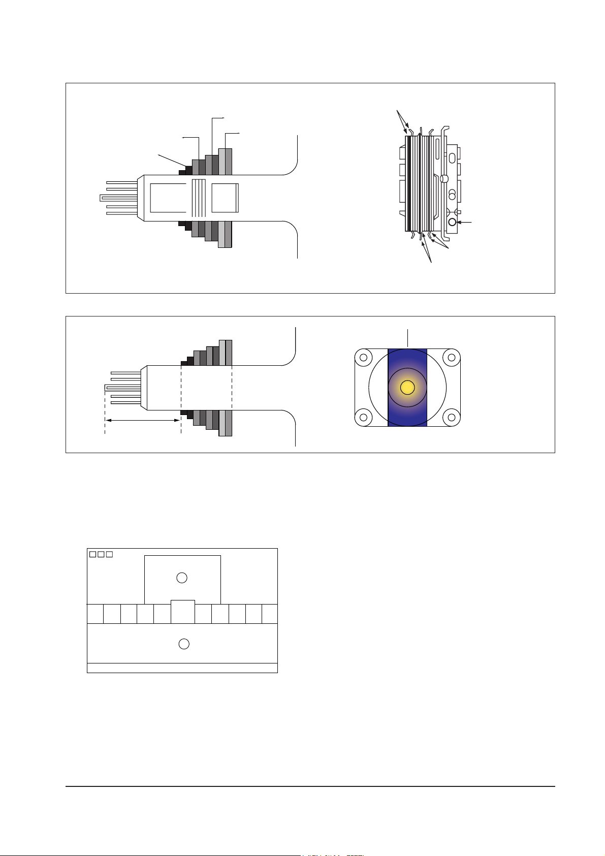
4-3-6 Purity Adjustment
1. Warm up the receiver for at least 20 minutes.
2. Plug in the CRT deflection yoke and tighten
the clamp screw.
3. Plug the convergence yoke into the CRT and
set in as shown in Fig. 4-1.
4. Input a black and white signal.
5. Fully demagnetize the receive by applying an
external degaussing coil.
6. Turn the CONTRAST and BRIGHTNESS
controls to maximum.
7. Loosen the clamp screw holding the yoke.
Slide the yoke backward or forward to provide
vertical green belt. (Fig. 4-2).
8. Tighten the convergence yoke.
9. Slowly move the deflection yoke forward, and
adjust for the best overall green screen.
10. Temporarily tighten the deflection yoke.
11. Produce blue and red rasters by adjusting the
low-light controls. Check for good purity in
each field.
12. Tighten the deflection yoke.
4-3-5 Screen Adjustment
1. Connect CRT socket pin RK to an oscilloscope
probe.
2. Input a gray scale pattern. (Use a pattern
generator, PM5518)
3. Use the P mode key (on the remote control) for
the STANDARD picture.
4. Adjust the Screen VR (on the FBT) so that the
voltage (See Fig.4-1.) on the oscilloscope
becomes 130 + 2.5V.
4-3-3 High Voltage Check
1. Connect a digital voltmeter to the second anode
of the picture tube.
2. Turn on the TV. Set the Brightness and
Contrast controls to minimum (zero beam
current).
3. The high voltage should not exceed 30KV.
4. Adjust the Brightness and contrast controls to
both extremes. Ensure that the high voltage
does not exceed 30KV under any conditions.
CAUTION: There is no high voltage adjustment on this
chassis. The B+power supply must be set to +130/155
volts. (Full color bar input and normal picture level).
Fig. 4-1
130V 2.5Vp-p
_
+
GND
H-Blanking
Page 9
4-9
Alignment and Adjustments
Samsung Electronics
Fig. 4-2 Convergence Magnet Assembly
31m/m
Vertical Green Belt
Fig. 4-3 Center Convergence Adjustment
2 POLE
PURITY
YOKE
CLAMP
SCREW
6 POLE
CONVERGENCE
4 POLE
CONVERGENCE
4 Pole Magnet
6 Pole Magnet
2 Pole Magnet
Clamper
Screw
Fig. 4-4
4-3-7 White Balance Adjustment
(a) Set up
1. Warm up the TV for at least 30 minutes in the
Aging Mode(Test Pattern). This mode is
displayed by entering the following sequence:
DISPLAY→FACTORY (Select Test Pattern)
2. Input a Toshiba pattern.
(b) High-Light Adjustment
1. Set SCT to 50 fL in the Factory Service
Mode using CA100. (See Fig. 4-4 ❶)
(c) Low-Light Adjustment
1. Set SBT to 1.2 fL in the Factory Service Mode
using CA100. (See Fig. 4-4 ❷ )
1
2
Page 10
Alignment and Adjustments
4-10 Samsung Electronics
1. Warm up the receiver for at least 20 minutes.
2. Adjust the Brightness and Contrast controls for
a well defined picture.
3. Adjust the two-tab pairs of the 4 pole magnets,
and change the angle between them.
Superimpose the red and the blue vertical lines
in the center area of the screen.
4. Turn the both tabs at the same time, keeping
the angle constant, and superimpose the red
and blue horizontal line in the center of the
screen.
5. Adjust the two-tab pairs of the 6-pole magnets
to superimpose the red and blue line onto the
green. (Changing the angle affects the vertical
lines, and rotating both magnets affects the
horizontal lines.)
6. Repeat adjustments 2~6, if necessary.
7. Since the 4-pole magnets and 6-pole magnets
interact, the dot movement is complex
(Fig. 4-3).
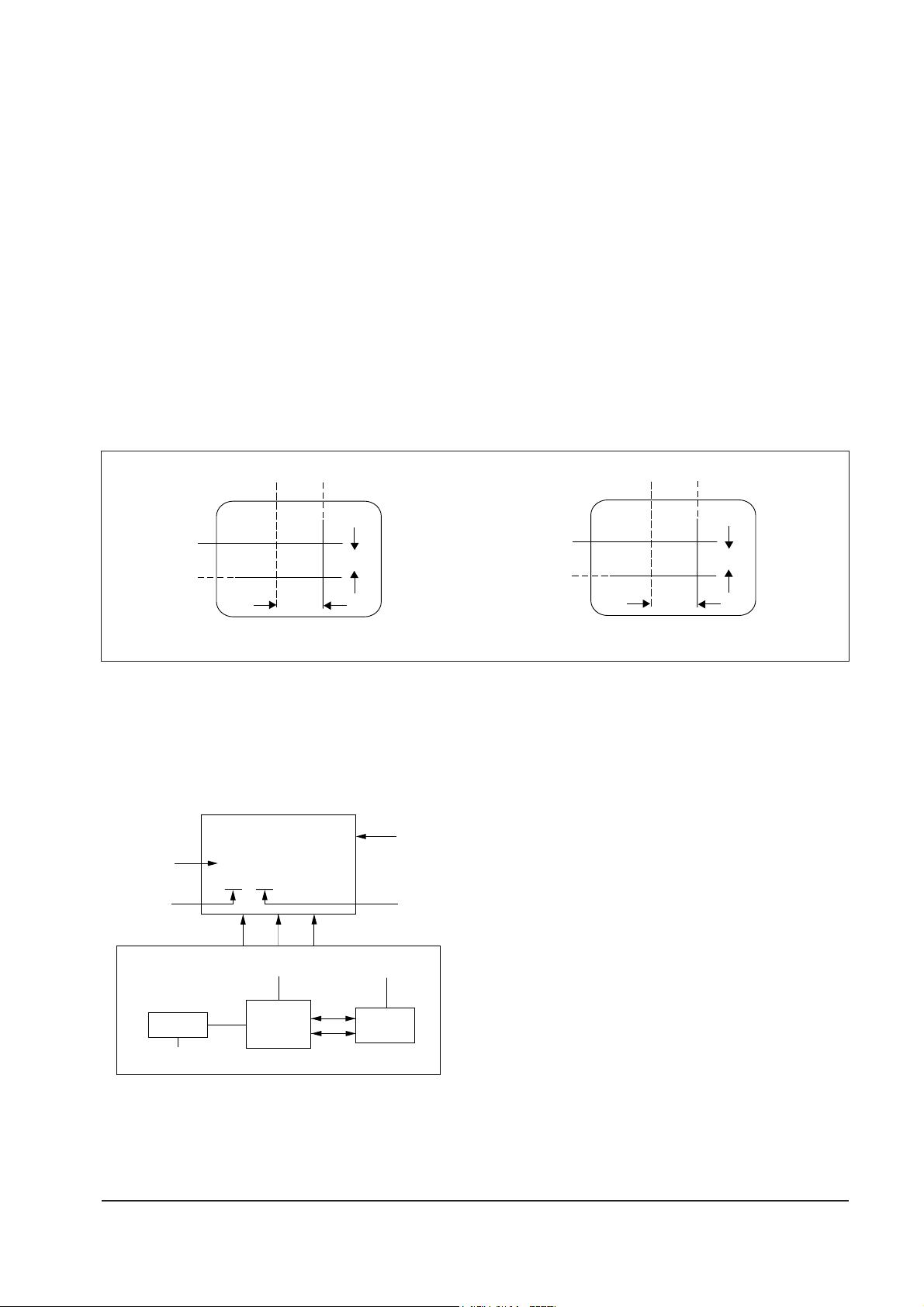
4-3-8 Center Convergence Adjustment
Fig . 4-5 Center Convergence Adjustment
RED
BLUE
BLUE
RED
4-Pole Magnet Movement
GREEN
RED/BLUE
RED/BLUE
GREEN
6-Pole Magnet Movement
4-3-9 VCO Adjustment
1. Turn on the TV.
2. Set IF port of a tuner to 38.9MHz. (Use a
pattern generator).
3. Input a color bar pattern(PAL-B/G system).
4. In the Factory Service Mode, select
"Adjustment → VCO" and set VCO data to 63.
5. Ensure "SD On" (Signal Input) and "SD Off"
(No Signal).
6. Adjust T201 (connected to TDA8844 pins3,4)
so that AFA Bit is "INSIDE WINDOW" (the
AFB Bit is 1).
Fig. 4-6
VCO 63
SD : ON
IN 1
SET
AFB
RGB
AFA
SIGNAL
DETECTOR
TUNER
IC201
(TDA8844)
IC902
IF (38.9MHz)
I2C-BUS
8V
5V
Page 11

4-3-11 Geometry Adjustment
(SC -> PVS -> PVA ->PSL -> PHS)
1. Input a Lion Head pattern.
2. SET the SC Data steps 10~12 in the Factory Mode.
3. Adjust with PVS (starts blinking) exactly at middle of the
screen.
4. Adjustment with PVA : Top and Bottom margins of the
picture are 4.
5. Adjustment with PSL : Bottom of picture to bottom of
screen.
6. Adjust PHS horizontally. Center the picture.
4-11
Alignment and Adjustments
Samsung Electronics
4
4
4-3-10 RF AGC Adjustment
1. Connect a pattern generator (PM5418) RF signal to tuner RF.
2. Select a gray scale pattern and PAL-B/G system.
Set to 479.25MHz.
3. Connect IC201 (ONECHIP) pin 53 to a digital multimeter.
4. Adjust AGC (using volume keys) in the Factory Service Mode.
Set IC201 (ONECHIP) pin 54 to 3.7 + 0.05v(DC).
5. Adjust AGC within 20 seconds after power ON.
Page 12

4-12 Samsung Electronics
MEMO
MEMO
 Loading...