

Page 1
COLOR TELEVISION RECEIVER
Chassis : S15A
Model: CK331FVR5X/NWT CK331FVR5X/BWT
CK331FVR5X/VWT CK501FVR5S/NWT
COLOR TELEVISION RECEIVER CONTENTS
Precautions
Specifications and IC Data
Disassembly and Reassembly
Alignment and Adjustment
Troubleshooting
Exploded View and Parts List
Electric Parts List
Block Diagram
PCB Layout Diagram
Wiring Diagram
Schematic Diagrams
1.
2.
3.
4.
5.
6.
7.
8.
9.
10.
11.
Page 2

ELECTRONICS
©
Samsung Electronics Co., Ltd. FEB.1999
Printed in Korea
3S15A-3121
Page 3

1. Precautions
1-1 Safety Precautions
1. Be sure that all of the built-in protective
devices are replaced. Restore any missing
protective shields.
2. When reinstalling the chassis and its
assemblies, be sure to restore all protective
devices, including: nonmetallic control knobs
and compartment covers.
3. Make sure that there are no cabinet openings
through which people—particularly
children—might insert fingers and contact
dangerous voltages. Such openings include
the spacing between the picture tube and the
cabinet mask, excessively wide cabinet
ventilation slots, and improperly fitted back
covers.
If the measured resistance is less than 1.0
megohm or greater than 5.2 megohms, an
abnormality exists that must be corrected
before the unit is returned to the customer.
4. Leakage Current Hot Check (Figure 1-1):
Warning: Do not use an isolation
transformer during this test. Use a leakagecurrent tester or a metering system that
complies with American National Standards
Institute (ANIS C101.1, Leakage Current for
Appliances), and Underwriters Laboratories
(UL Publication UL1410, 59.7).
5. With the unit completely reassembled, plug
the AC line cord directly into the power
outlet. With the unit’s AC switch first in the
ON position and then OFF, measure the
current between a known earth ground (metal
water pipe, conduit, etc.) and all exposed
metal parts, including: antennas, handle
brackets, metal cabinets, screwheads and
control shafts. The current measured should
not exceed 0.5 milliamp. Reverse the powerplug prongs in the AC outlet and repeat the
test.
Fig. 1-1 AC Leakage Test
6. Antenna Cold Check:
With the unit’s AC plug disconnected from the
AC source, connect an electrical jumper across
the two AC prongs. Connect one lead of the
ohmmeter to an AC prong. Connect the other
lead to the coaxial connector.
7. X-ray Limits:
The picture tube is especially designed to prohibit X-ray emissions. To ensure continued
X-ray protection, replace the picture tube only
with one that is the same type as the original.
Carefully reinstall the picture tube shields and
mounting hardware; these also provide X-ray
protection.
8. High Voltage Limits:
High voltage must be measured each time servicing is done on the B+, horizontal deflection
or high voltage circuits. Correct operation of
the X-ray protection circuits must be
reconfirmed whenever they are serviced.
(X-ray protection circuits also may be called
“horizontal disable” or “hold-down”.)
Heed the high voltage limits. These include
the X–ray Protection Specifications Label, and
the Product Safety and X-ray Warning Note on
the service data schematic.
Precautions
Samsung Electronics 1-1
LEAKAGE
CURRENT
TESTER
DEVICE
UNDER
TEST
TEST ALL
EXPOSED METAL
SURFACES
2-WIRE CORD
ALSO TEST WITH
PLUG REVERSED
(USING AC ADAPTER
PLUG AS REQUIRED)
EARTH
GROUND
(READING SHOULD
NOT BE ABOVE
0.5mA)
Follow these safety, servicing and ESD precautions to prevent damage and protect against potential
hazards such as electrical shock and X-rays.
Page 4
1-1 Safety Precautions (Continued)
9. High voltage is maintained within specified
limits by close-tolerance, safety-related
components and adjustments. If the high
voltage exceeds the specified limits, check
each of the special components.
10. Design Alteration Warning:
Never alter or add to the mechanical or
electrical design of this unit. Example: Do not
add auxiliary audio or video connectors. Such
alterations might create a safety hazard. Also,
any design changes or additions will void the
manufacturer’s warranty.
11. Hot Chassis Warning:
Some TV receiver chassis are electrically
connected directly to one conductor of the AC
power cord. If an isolation transformer is not
used, these units may be safely serviced only
if the AC power plug is inserted so that the
chassis is connected to the ground side of the
AC source.
To confirm that the AC power plug is inserted
correctly, do the following: Using an AC
voltmeter, measure the voltage between the
chassis and a known earth ground. If the
reading is greater than 1.0V, remove the AC
power plug, reverse its polarity and reinsert.
Re-measure the voltage between the chassis
and ground.
12. Some TV chassis are designed to operate with
85 volts AC between chassis and ground,
regardless of the AC plug polarity. These units
can be safely serviced only if an isolation
transformer inserted between the receiver and
the power source.
13. Some TV chassis have a secondary ground
system in addition to the main chassis ground.
This secondary ground system is not
isolated from the AC power line. The two
ground systems are electrically separated by
insulating material that must not be defeated
or altered.
14. Components, parts and wiring that appear to
have overheated or that are otherwise
damaged should be replaced with parts that
meet the original specifications. Always
determine the cause of damage or overheating, and correct any potential hazards.
15. Observe the original lead dress, especially
near the following areas: Antenna wiring,
sharp edges, and especially the AC and high
voltage power supplies. Always inspect for
pinched, out-of-place, or frayed wiring. Do
not change the spacing between components
and the printed circuit board. Check the AC
power cord for damage. Make sure that leads
and components do not touch thermally hot
parts.
16. Picture Tube Implosion Warning:
The picture tube in this receiver employs
“integral implosion” protection. To ensure
continued implosion protection, make sure
that the replacement picture tube is the same
as the original.
17. Do not remove, install or handle the picture
tube without first putting on shatterproof
goggles equipped with side shields. Never
handle the picture tube by its neck. Some
“in-line” picture tubes are equipped with a
permanently attached deflection yoke; do not
try to remove such “permanently attached”
yokes from the picture tube.
18. Product Safety Notice:
Some electrical and mechanical parts have
special safety-related characteristics which
might not be obvious from visual inspection.
These safety features and the protection they
give might be lost if the replacement component differs from the original—even if the
replacement is rated for higher voltage,
wattage, etc.
Components that are critical for safety are
indicated in the circuit diagram by shading,
( ) or ( ).
Use replacement components that have the
same ratings, especially for flame resistance
and dielectric strength specifications.
A replacement part that does not have the
same safety characteristics as the original
might create shock, fire or other hazards.
Precautions
1-2 Samsung Electronics
!
Page 5

1-2 Servicing Precautions
1. Servicing precautions are printed on the
cabinet. Follow them.
2. Always unplug the unit’s AC power cord from
the AC power source before attempting to: (a)
Remove or reinstall any component or
assembly, (b) Disconnect an electrical plug or
connector, (c) Connect a test component in
parallel with an electrolytic capacitor.
3. Some components are raised above the printed
circuit board for safety. An insulation tube or
tape is sometimes used. The internal wiring is
sometimes clamped to prevent contact with
thermally hot components. Reinstall all such
elements to their original position.
4. After servicing, always check that the screws,
components and wiring have been correctly
reinstalled. Make sure that the portion around
the serviced part has not been damaged.
5. Check the insulation between the blades of the
AC plug and accessible conductive parts
(examples: metal panels, input terminals and
earphone jacks).
6. Insulation Checking Procedure: Disconnect the
power cord from the AC source and turn the
power switch ON. Connect an insulation
resistance meter (500V) to the blades of the AC
plug.
The insulation resistance between each blade
of the AC plug and accessible conductive parts
(see above) should be greater than 1 megohm.
7. Never defeat any of the B+ voltage interlocks.
Do not apply AC power to the unit (or any of
its assemblies) unless all solid-state heat sinks
are correctly installed.
8. Always connect a test instrument’s ground
lead to the instrument chassis ground before
connecting the positive lead; always remove
the instrument’s ground lead last.
Precautions
Samsung Electronics 1-3
Warning1: First read the “Safety Precautions” section of this manual. If some unforeseen circumstance creates a conflict between
the servicing and safety precautions, always follow the safety precautions.
Warning2: An electrolytic capacitor installed with the wrong polarity might explode.
Page 6

1. Some semiconductor (“solid state”) devices
are easily damaged by static electricity. Such
components are called Electrostatically
Sensitive Devices (ESDs); examples include
integrated circuits and some field-effect
transistors. The following techniques will
reduce the occurrence of component damage
caused by static electricity.
2. Immediately before handling any semicon
ductor components or assemblies, drain the
electrostatic charge from your body by
touching a known earth ground. Alternatively,
wear a discharging wrist-strap device. (Be
sure to remove it prior to applying power—
this is an electric shock precaution.)
3. After removing an ESD-equipped assembly,
place it on a conductive surface such as
aluminum foil to prevent accumulation of
electrostatic charge.
4. Do not use freon-propelled chemicals. These
can generate electrical charges that damage
ESDs.
5. Use only a grounded-tip soldering iron when
soldering or unsoldering ESDs.
6. Use only an anti-static solder removal device.
Many solder removal devices are not rated as
“anti-static”; these can accumulate sufficient
electrical charge to damage ESDs.
7. Do not remove a replacement ESD from its
protective package until you are ready to
install it. Most replacement ESDs are
packaged with leads that are electrically
shorted together by conductive foam,
aluminum foil or other conductive materials.
8. Immediately before removing the protective
material from the leads of a replacement ESD,
touch the protective material to the chassis or
circuit assembly into which the device will be
installed.
9. Minimize body motions when handling
unpackaged replacement ESDs. Motions such
as brushing clothes together, or lifting a foot
from a carpeted floor can generate enough
static electricity to damage an ESD.
Precautions
1-4 Samsung Electronics
1-3 Precautions for Electrostatically Sensitive Devices (ESDs)
Page 7

Specifications and IC Data
Samsung Electronics 2-1
2. Specifications and IC Data
2-1 Specifications
Television System:
Channels:
Intermediate Frequencies (MHz) :
Picture Tube:
Power Requirements:
Antenna Input Impedance:
Speaker Impedance
NTSC - M
2 - 13
14-69
NTSC - M
38.90
34.40
35.32
PAL/SECAM-
B/G,I
2 - 12
21 - 69
PAL/
SECAM- B/G
38.90
33.40
34.47
System
Band
VHF
UHF
SYSTEM
IF Carrier Frequency
Picture IF Carrier
Sound IF Carrier
Color Sub Carrier
PAL,
SECAM- D/K
1 - 13
21 - 69
PAL/SECAM-D/K,
SECAM-K1
38.90
32.40
34.47
SECAM-K1,
PAL-D
2 - 9
13 - 57
PAL - I
38.90
32.90
34.47
MODEL
CI
CII
CX
CK
CW
CS
14 Inch
20 Inch
21 Inch
AC 100~260V, 50/60Hz
VHF, UHF : Telescopic dipole antenna (75 ohm unbalanced type )
8 ohm, 5W+5W (Dual Type)
16 ohm, 3W (Monitor Type & Dual Type)
SYSTEM
PAL-I (UHF)
PAL-I (VHF/UHF)
PAL-B/G, SECAM-B/G
PAL-B/G, D/K, SECAM-B/G, D/K
PAL-B/G, D/K, SECAM-B/G, D/K, NT 4.43
PAL-B/G, D/K, SECAM-B/G, D/K, NT4.43, NT3.58
A34KQV42X
A48KRD82X(H)
A51KQJ63X
Quick start, in-line-gun,
Black stripe, 90
degree deflection
Page 8
2-2 IC Line Up
Specifications and IC Data
2-2 Samsung Electronics
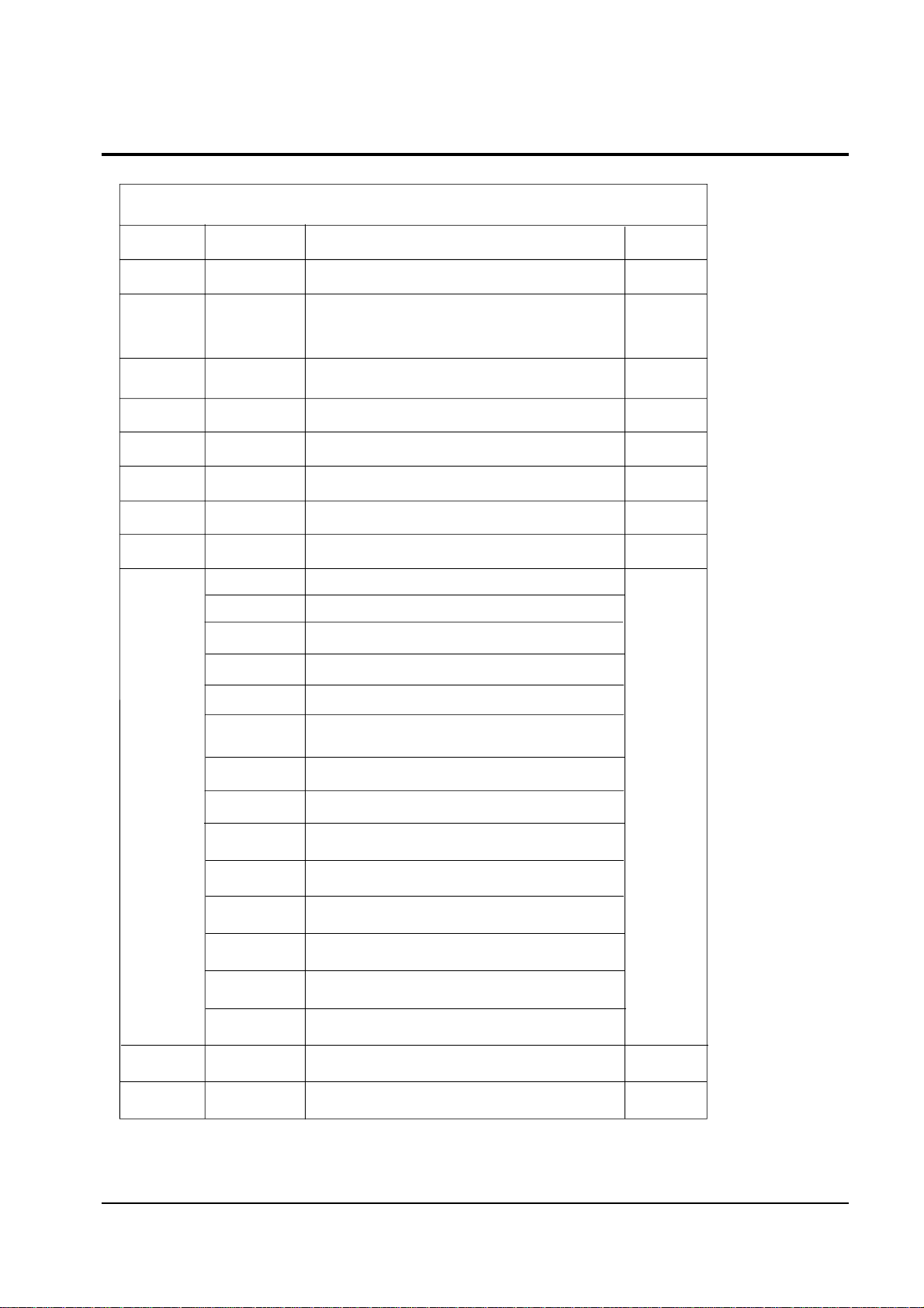
Loc. No Specification Description Remark
HC101 PAP103 IF PRE-AMP
IC201 TDA8842 PAL/SECAM-B/G, D/K, NTSC
Philips
TDA8841 PAL-B/G, D/K, NTSC
IC301 TDA8356 VERTICAL OUTPUT
IC501 TDA6107Q RGB DRIVE AMP
IC601 TDA7056B SOUND-AMP (3W x 1CH or 3W x 2CH)
IC602 TDA7057AQ SOUND-AMP (5W x 2CH)
IC801 KA3S0680RF POWER IC (STR)
IC802 KA7630 CUSTOM REGULATOR (5V, 8V)
Table 2-1 IC Line-Up
SZM173EA W/O TTX, English/French/Arabian
SZM173EC W/O TTX, English/Chinese
SZM173ET W/O TTX, English/Thai
SZM173EW W/O TTX, English/German/French/Dutch/Italian/Spanish,
Swedish/Yugo/Greek/Croatian
SZM173EE W/O TTX,English/Romanian/Hungarian/Polish/Czech/Bulgarian
SZM173ER W/O TTX, English/Russian
SPM175EE TTX, West : English/German/French/Dutch/Italian/Spanish/Swedish
East : English/Czech/Croatian/Romanian/Hungarian/Polish
SZM173EV W/O TTX, English/Vietnamese/Indonesian/Malay
IC902 24C04/KS24C040 EEPROM
PC801 TCET1108 / LTV817B PHOTO COUPLER
SPM175ER TTX, English/Russian/Bulgarian
SPM175EP TTX, English/Iranian
SPM175EA TTX, English/French/Arabian
SPM175EG TTX, English/Greek/Yugo
Dual Type
Zilog
(Non TTX)
Philips
(TTX)
IC901
SZM173AR W/O TTX, English/Arabian
SPM175E TTX, English/French/Swiss
Page 9

2-3 Semiconductor Base Diagrams
Specifications and IC Data
Samsung Electronics 2-3
ELECTROLYTICCONDENSER
IC
DIODE
TDA884X(Pin 56)
Z8933112PSC(Pin 42)
X24CO4P(Pin 8)
SAA5291(Pin 52)
TDA9859(Pin 32)
KS24C040(Pin 8)
IC
TRANSISTOR
TDA8133
TDA8356
TDA6101Q
KA7630
TRANSISTOR
TRANSISTOR
2SD1651
2SD1650
KSD5072
KSD5071
KSD1711
KSC5386
B
C
E
E B C
KSC815-Y
KSA539-Y
BC548
KTC9014
IC
UPC574J
or
KA33V
SAW-FILTER
E C B
KSR1012
KSR1010
KSR2010
KTD863-Y
1
1
1
K2971M
K7252M
Fig. 2-1 Semiconductor Base Diagrams
Page 10

2-4 Samsung Electronics
MEMO
Page 11
Disassembly and reassembly
Samsung Electronics 3-1
3. Disassembly and Reassembly
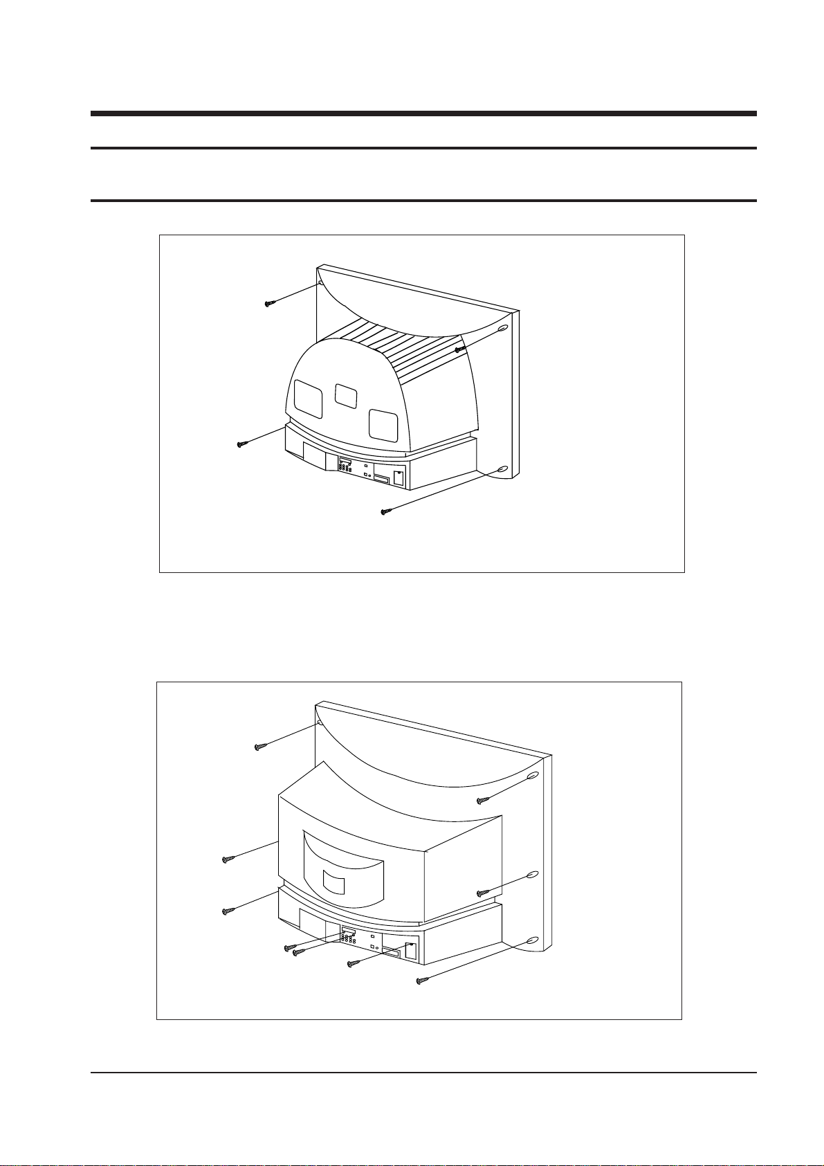
3-1 Back Cover Removal
1. After removing the screws, press the tension rib and pull the cabinet backwards.
2. To reassemble, press the tension rib (see diagram).
Page 12
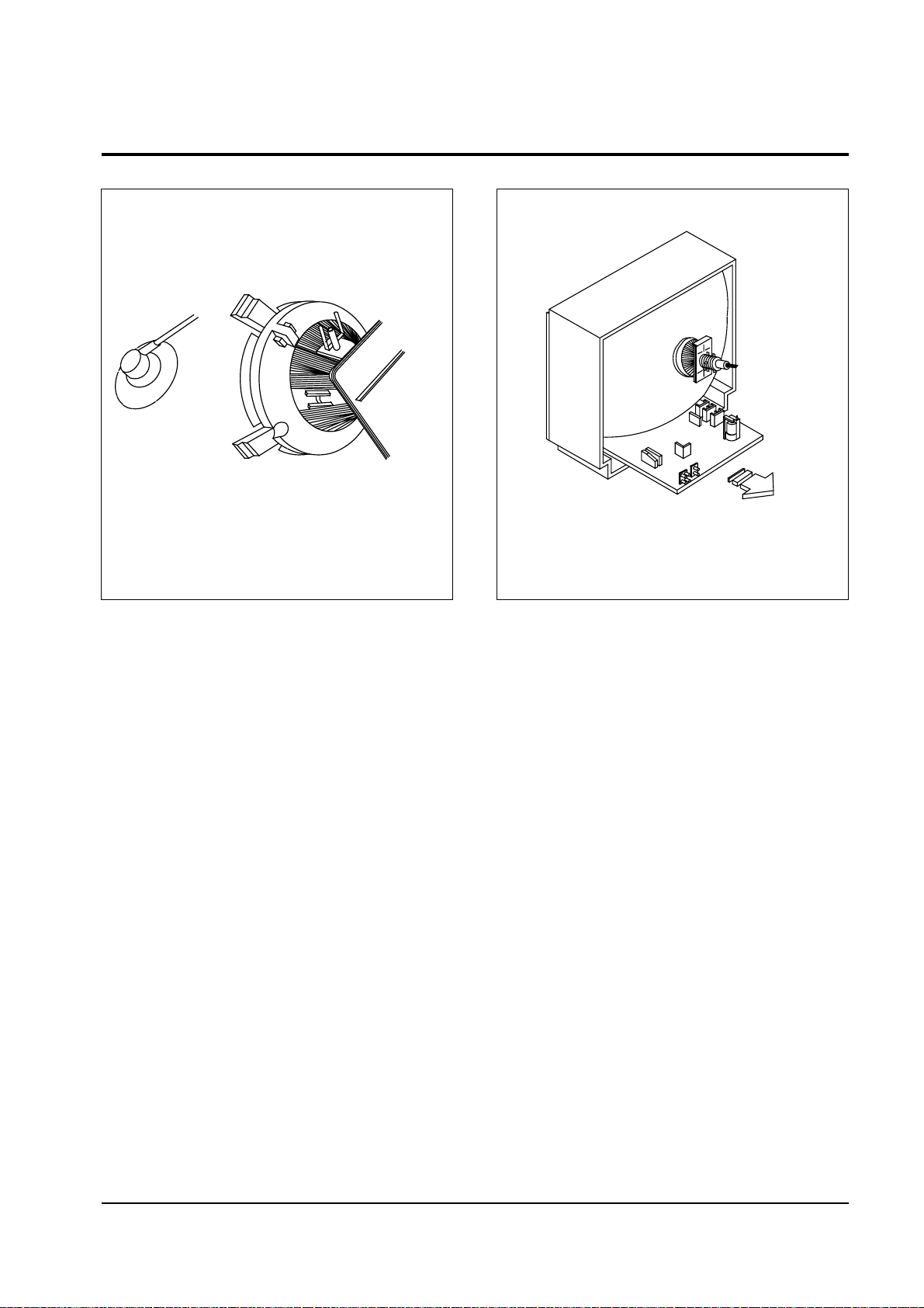
3-2 Main Board Removal
Disassembly and reassembly
3-2 Samsung Electronics
1. Separate the socket board from the CRT neck.
2. Remove the Anode Cap from the CRT.
3. Remove the main board by pulling it with both hands.
Warning: The FBT is charged with high voltage.
Before removing the Anode Cap, discharge the voltage
through one of the heat sinks on the main board.
Page 13

3-3 Speaker Removal
Disassembly and reassembly
Samsung Electronics 3-3
1. Remove the speaker by
pressing the tension rib.
1. Remove the screws.
2. Remove the speaker by
pressing the tension rib.
Page 14
Disassembly and reassembly
3-4 Samsung Electronics
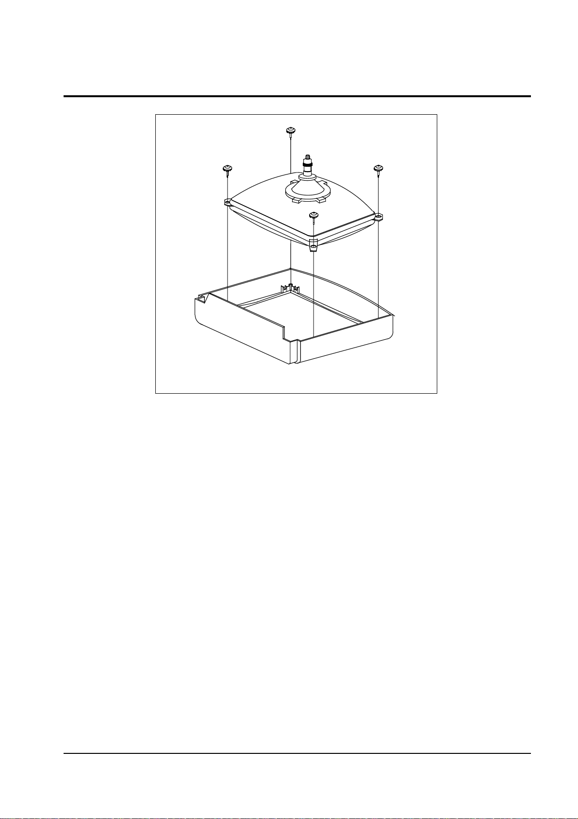
3-4 CRT Removal
1. Spread a soft mat on the floor. Place the TV set face
down.
2. Remove the 4 nuts mounting the CRT to the front cabinet. Lift the CRT.
3. Caution: Because of the high vacuum and large surface
area of the picture tube, be careful while handling it: (1)
Always lift the picture tube by grasping it firmly around
the faceplate, (2) Never lift the tube by its neck. (3) Do
not scratch the picture tube or apply excessive pressure.
Fractures of the glass may cause an implosion.
Page 15

Alignment and Adjustments
Samsung Electronics 4-1
4. Alignment and Adjustments
4-1 Preadjustment
4-1-1 Factory Mode
1. Do not attempt these adjustments in the Video
Mode.
2. The Factory Mode adjustments are necessary
when either the EEPROM (IC902) or the CRT
is replaced.
3. Do not tamper with the ÒAdjustmentÓ screen
of the Factory Mode menu. This screen is
intended only for factory use.
4-1-2 When EEPROM (IC902) Is Replaced
1. When IC902 is replaced all adjustment data
revert to initial values. It is necessary to
re-program this data.
2. After IC902 is replaced, warm up the TV for
10 seconds.
4-1-3 When CRT Is Replaced
1. Make the following adjustments AFTER setting up after setting up purity and convergence :
White Balance
Sub-Brightness
Vertical Center
Vertical Size
Horizontal Size
Fail Safe (This adjustment must be the last
step).
2. If the EEPROM or CRT is replaced, set PVA to
45 (factory mode) and set SC as follows.
14, 16 inch : 0
20 inch : 10
21 inch : 12
4-2 Factory/Service Mode
4-2-1 Procedure for the “Adjustment” Mode
1. This mode uses the standard remote control.
The Service Mode is activated by entering the
following remote-control sequence :
(1) SLEEP®FACTORY.
(2) STAND-BY® DISPLAY® P.STD® MUTE
®POWER ON.
2. The ÒSERVICE (FACTORY)Ó message will be
displayed. The Service Mode has four components: Adjustment, Test Pattern, Option Bytes
and Reset.
3. Access the Adjustment Mode by pressing the
ÒVOLUMEÓ keys ( Up or Down). The adjustment parameters are listed in the accompanying table, and selected by pressing the CHAN-
NEL keys (▲ ,▼).
4. Selection sequences for the all system:
DOWN or UP key:
AGC>VCO>SBT>SCT>SCR>SC>RG>GG>
BG>CDL>BLU>PSL>PVS>PVA>PHS>NSR>
STT
5. The VOLUME keys increase or decrease the
adjustment values (stored in the
non-volatile memory) when Adjustment Mode
is cancelled.
6. Cancel the Adjustment Mode by re-pressing
the ÒFACTORYÓ or ÒPower OFFÓ keys.
Page 16
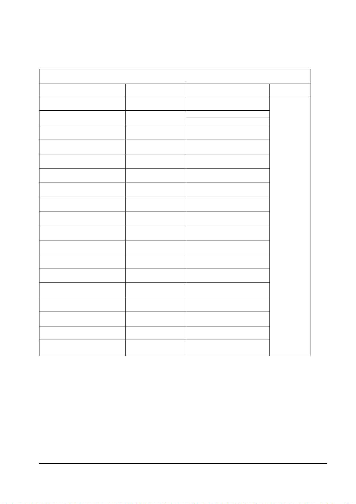
4-2-2 Main Adjustment Parameter
NOTE : PVS,PVA, PHS, parameters must be aligned using the 50Hz vertical-field rates.
Alignment and Adjustments
4-2 Samsung Electronics
INITIAL DATA
10
8
10
10
47
32
34
32
32
42
40
7
0
80
12
4
0
REMARK
TDA8842
TDA8841
RANGE
0 ~ 63 STEP
0 ~ 23 STEP
0 ~ 23 STEP
0 ~ 23 STEP
0 ~ 63 STEP
0 ~ 63 STEP
0 ~ 63 STEP
0 ~ 63 STEP
0 ~ 63 STEP
0 ~ 63 STEP
0 ~ 63 STEP
0 ~ 23 STEP
1 ~ 13 STEP
0 ~ 128 STEP
0 ~ 1 STEP 1 (For East Europe)
0 ~ 63 STEP
0 ~ 63 STEP 16 (Only TTX Model)
0 ~ 7 STEP
0 ~ 3 STEP
OSD ABBREVIATION
AGC
SBT
SCT
SCR
RG
GG
BG
PSL
PVS
PVA
PHS
NSR
STT
VCO
SC
TSS
CDL
BLU
FUNCTION
AUTO GAIN CONTROL
SUB BRIGHT
SUB CONTRAST
SUB COLOR
RED DRIVE GAIN
GREEN DRIVE GAIN
BLUE DRIVE GAIN
PAL VERTICAL SLOPE
PAL VERTICAL SHIFT
PAL VERTICAL AMPLITUDE
PAL HORIZONTAL SHIFT
NTSC SUB COLOR
SUB TINT
VOLTAGE CONTROL OSCILLATOR
S-CORRECTION
TTX SUB-CONTRAST
CATHODE DRIVE LEVEL
BLUE STRETCH MODE
m
Table 4-1 Main Adjustment Parameter (Zilog, Phlips -com)
Page 17
Alignment and Adjustments
Samsung Electronics 4-3
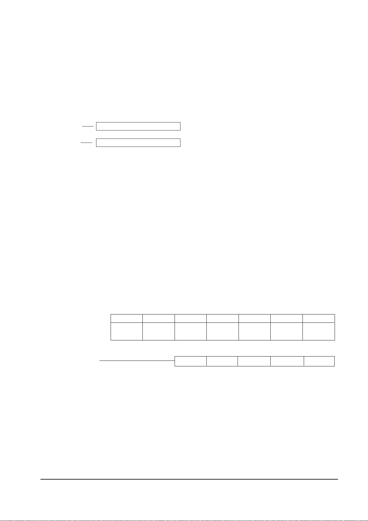
4-2-3 Test Pattern (Aging Mode)
1. This mode can be used during servicing, or for confirming that the convergence and
purity adjustments are correct.
2. Access the Test Pattern parameters by pressing a CHANNEL keys (▲ ,▼) while the
Service Mode is on. The cursor will move to the test pattern. Press the VOLUME
keys. On-screen display:
•
WHITE
•
AGING
3. AGING Mode (Reference Only)
This pattern is used for pre-heating the CRT during manufacturing
Ñit is accessed in the factory by twice pressing the ÒSLEEP ® FACTORY®FACTORY
Ò key, then white pattern will be displayed.
Even if the TV power is cut off, the Aging Mode is not cancelled, The aging mode is
cancelled by repressing the ÒFACTORYÓ key or pressing the local ÒCH UP/DOWNÓ
keys.
4-2-4 Option Bytes
In the Service Mode, various can be selected via the Option Bytes (8 bits each). Example:
NON -TTX MICOM ONLY
TTX MICOM
SYSTEM OSD DISPLAY
BYTE 0 : 8 BYTE 1 : 0 -
TDA8842, CK SYSTEM, RCA JACK SYSTEM OSD DISPLAY
BYTE 0 : 11
BIT 6
L (BIT :0)
BIT 5
L (BIT : 0)
BIT 4
L (BIT : 0)
L (BIT : 0)
L (BIT : 1) H (BIT : 0) L (BIT : 0) H (BIT : 0) L (BIT : 1)
BIT 3
H (BIT : 8)
L (BIT : 0)
BIT 2
L (BIT : 0)
L (BIT : 0)
BIT 1
L (BIT : 0)
L (BIT : 0)
BIT 0
L (BIT : 0)
L (BIT : 0)
Page 18
Alignment and Adjustments
4-4 Samsung Electronics
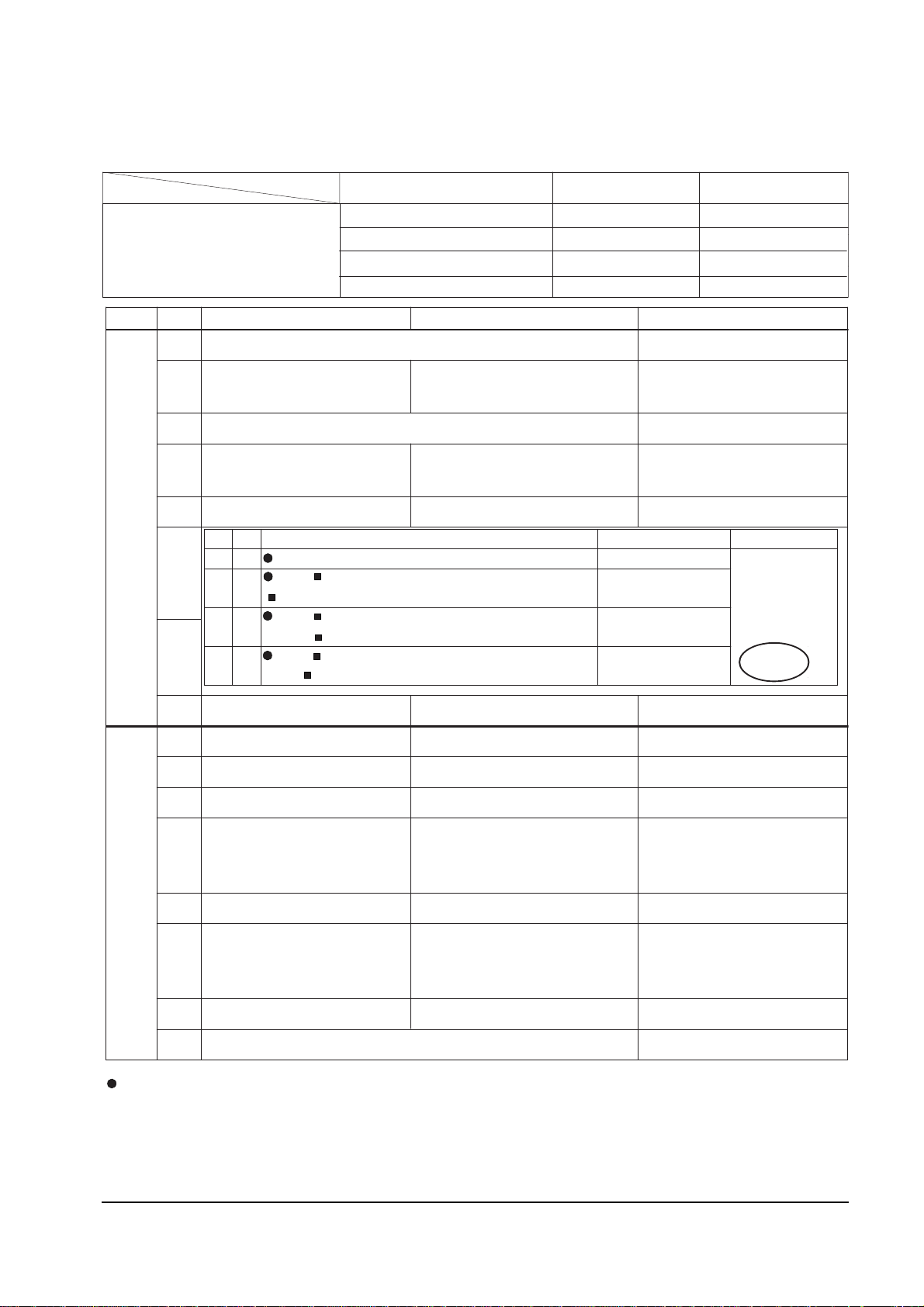
4-2-4 (A) NON-TTX MICOM (SZM-173EC) OPTION BYTE (FOR CHINA/SINGAPORE/GERMAN ARMY)
BYTE BIT LOW (0) HIGH (1) Application MICOM
B
Y
T
E
0
D7 NOT USED MUST LOW
D6
TV : NORMAL ZOOM
A/V :NORMAL ZOOM
TV: NORMAL ZOOM 16:9
A/V : NORMAL ZOOM
D5 NOT USED MUST = LOW
D4
CH Up/down functional in
the A/V Mode (SCART Jack)
CH Up/down not functional in
the A/V Mode (RCA Jack)
D3 Sound-I System Used Sound-I System Not Used
D2
D1
D0 TDA8374A TDA8842 IC201 (ONE-CHIP) OPTION
B
Y
T
E
1
D7 TV OUT MONITOR OUT
D6 English ONLY English/Chinese
D5 AFT ON (always) AFT OFF (after fine tuning) BASIC = LOW
D4
Existing Sharpness level
(when using the TDA6108
RGB AMP)
Sharpness level up
(when using the TDA6107Q
RGB AMP)
D3 No Auto Power On Auto Power On
D2
NTSC : 25KHz (NTSC TABLE
)
PAL : 50KHz (PAL TABLE)
NTSC : 25KHz (NTSC TABLE)
PAL : 27KHz (NTSC TABLE)
D1
NOT USED MUST LOW
D0
D2 D1
COLOR SYSTE M SOUND SYSTEM Re mark
0 0
CB : NO OSD
German Army : CS
0 1
CW : RF : AUTO PAL SECAM NT4.43
A/V : AUTO PAL SECAM NT4.43 NT3.58
B/G D/K I
1 0
CD : RF : AUTO PAL NT4.43
A/V : AUTO PAL NT4.43 NT3.58
D/K I
1 1
CS : RF: AUTO PAL SECAM NT4.43 NT3.58
A/V: AUTO PAL SECAM NT4.43 NT3.58
B/G D/K (I)
NT- M
D3 BIT
OPTION
Function Required : 1. PICTURE OFF (after 15 minutes) during no signal
2. AUDIO MUTE during no signal
3. BLUE SCREEN ON/OFF
4. TIMER CLOCK ON/OFF
5. No CHILD LOCK
Destination BYTE 0 BYTE 1
MP (Massproduction)
OPTION BYTE
China 15 58
Singapore 57 58
German Army 5757 18
®Ÿ
®Ÿ
®Ÿ
®Ÿ
®Ÿ
®Ÿ
®Ÿ
®Ÿ
®Ÿ
®Ÿ
®Ÿ
®Ÿ
®Ÿ
®Ÿ
®Ÿ
®Ÿ ®Ÿ
®Ÿ
®Ÿ
®Ÿ
®Ÿ
®Ÿ
®Ÿ
®Ÿ
®Ÿ
®Ÿ
®Ÿ
®Ÿ
«Ÿ
®Ÿ
®Ÿ
®Ÿ
®Ÿ
®Ÿ
MUST = LOW : China (only)
16 : 9 (Delete)
MUST = HIGH
China MP : CD
"?"
"?"
"?"
MUST = HIGH
BASIC = HIGH
BASIC = HIGH
®Ÿ
Hotel ( CB )
59
1A
Others
HOTEL
Page 19
Alignment and Adjustments
Samsung Electronics 4-5
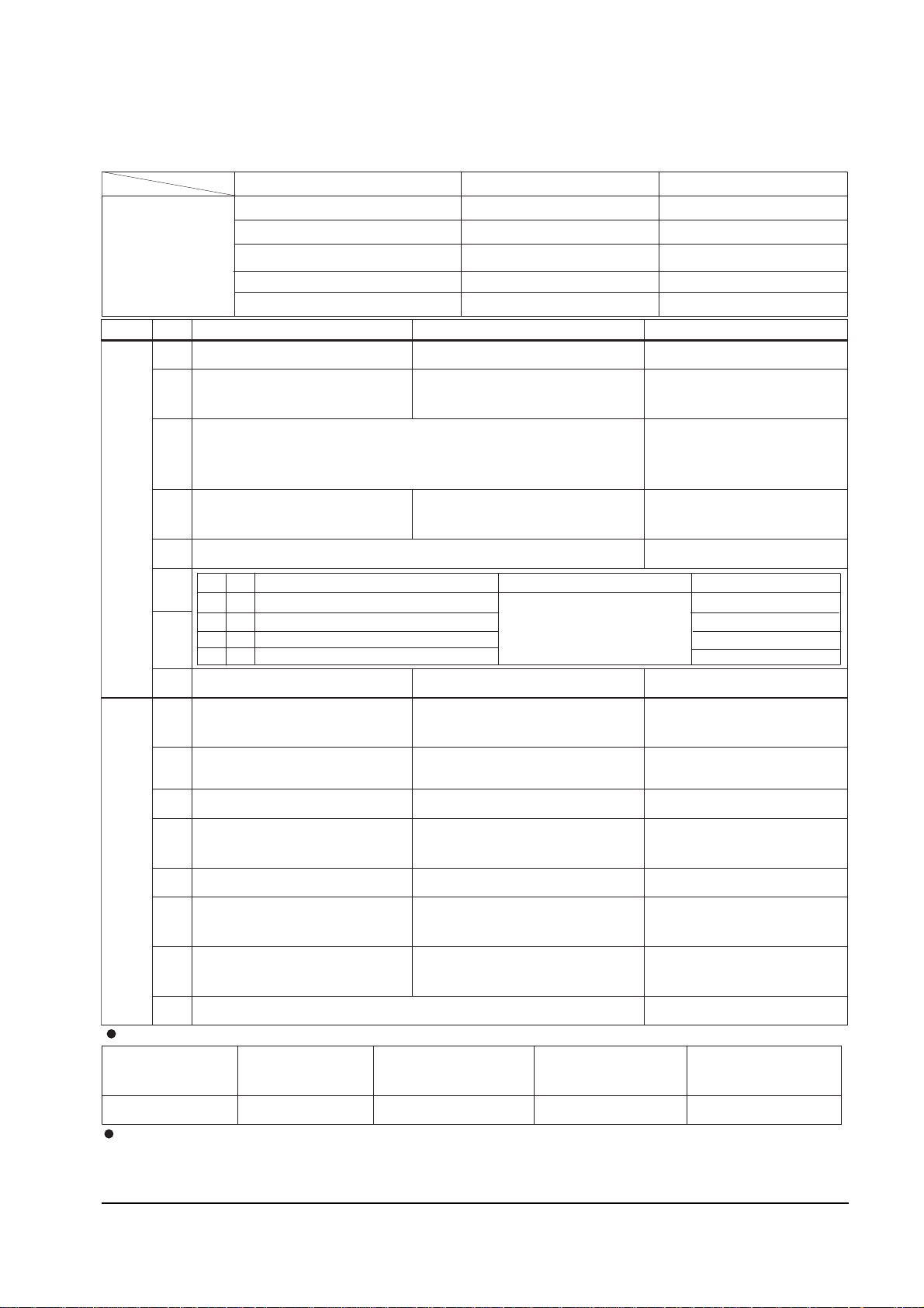
4-2-4 (B) NON-TTX MICOM (SZM-173EW/EE) OPTION BYTE (FOR EUROPE)
BYTE BIT LOW(0) HIGH(1) Remark
B
Y
T
E
0
D7
3BAND UHF ONLY
HIGH (UK only)
D6
TV : NORMAL ZOOM
A/ : NORMAL ZOOM
TV : NORMAL
ZOOM 16:9
A/V : NORMAL ZOOM
MUST = HIGH
D5 MUST LOW - R913 : 680 added
- J901 :
D4
CH Up/down functional in the
A/V Mode (SCART Jack)
CH Up/down not functional in
the A/V Mode (RCA Jack)
MUST = LOW
D3
NOT USED MUST = LOW
D
2
D
1
D0 TDA8374A TDA8842 IC201 (ONE-CHIP) OPTION
B
Y
T
E
1
D7
English/German/Dutch/Italian/Spnish/
Swedish/Croatian/Yugo/Greek/French
Western Europe
(SZM-173EW/EW1)
D6
English/Romanian/Hungarian/Polish/
Czech
/B ulgarian
Eastern Europe (SZM-173EE)
D5 AFT ON (always) AFT OFF (after fine tuning) MUST = LOW
D4
Existing sharpness level :
TDA6108
Sharpness level up : TDA6107Q MUST = HIGH
D3 No Auto Power On Auto Power On
D2
NTSC : 25 KHz (NTSC TABLE)
PAL : 50 KHz (PAL TABLE)
NTSC : 25KHz(NTSC TABLE)
PAL : 27KHz(NTSC TABLE)
D1 PAL / SECAM SECAM - L
- France/Swiss (only) : HIGH
D0 MUST : LOW
D2 D1
SOUND SYSTEM COLOR SYSTEM Destination
0 0 "?"
B/G D/K : CK MODEL
AUTO : NO OSD
Eastern Europe/France/Swiss
0 1 I ONLY ( NO OSD ) : CI,CII MDL United Kingdom
1 0 B/G ONLY (NO OSD ) : CB,CX MDL Western Europe
1 1 NOT USED
Destination BYTE 0 BYTE 1
MP OPTION
BYTE
United Kingdom C3 98
France/Swiss 45 9A
Western Europe (except UK) 45 98
Eastern Europe 41 58
P-STD Classification ( CON./BRI./SHAR./COL )
STANDARD
MODE
DYNAMIC
MODE
MOVIE MODE MILD MODE CUSTOM MODE
90/50/50/50 100/50/75/50 90/50/75/50 60/50/50/50 90/50/50/50
Function Required: 1. PICTURE OFF (after 15 minutes) during no signal. 2. AUDIO MUTE during no
3. No BLUE SCREEN during no RF signal (Blue Screen during AV).
4. No TIMER. 5. No CHILD LOCK. 6. See "Detailed functions of CF".
®Ÿ
®Ÿ
®Ÿ
®Ÿ
®Ÿ
W
®Ÿ «Ÿ
signal.
MUST = HIGH
delete
POLAND OPTION
Ireland (CII)
43
98
Page 20
Alignment and Adjustments
4-6 Samsung Electronics
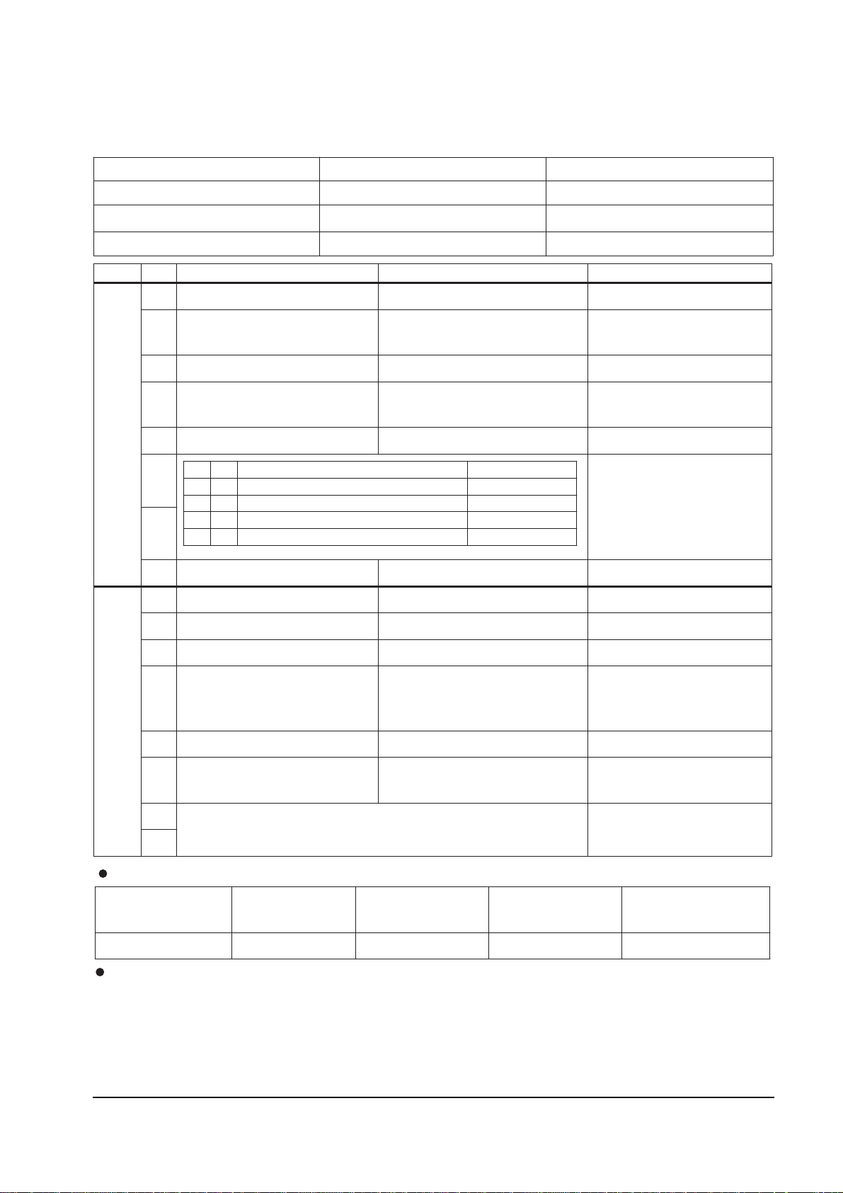
4-2-4 C) NON-TTX MICOM (SZM-173ER) OPTION BYTE (FOR RUSSIA)
Destination BYTE 0 BYTE 1
Russia,CIS 49 58
Australia 5D 18
BYTE BIT LOW(0) HIGH(1) Remark
B
Y
T
E
0
D7
D6
TV : NORMAL
ZOOM
A/V : NORMAL ZOOM
TV : NORMAL ZOOM 16:9
A/V : NORMAL ZOOM
D5
D4
CH Up/down functional in the
A/V Mode (SCART Jack)
CH Up/down not functional in
the A/V Model (RCA Jack)
D3 PAL-I Used PAL-I Not Used
D
2
D
1
D0 TDA8374A TDA8842 IC201 (ONE-CHIP) OPTION
B
Y
T
E
1
D7
D6 English English/Russian
D5 AFT ON (always) AFT OFF (after fine tuning)
D4
Existing sharpness level
(when using the TDA6108 RGB AMP)
Sharpness level up
(when using the TDA6107Q AMP)
D3 No Auto Power On Auto Power On
D2
NTSC: 25 KHz (NTSC TABLE)
PAL : 50 KHz (PAL TABLE)
NTSC : 25 KHz (NTSC TABLE)
PAL : 27 KHz (NTSC TABLE)
D1
D0
Function Required : 1. PICTURE OFF (after 15 minutes) during no signal
2. AUDIO MUTE during no signal
SCREEN available
4. TIMER available
5.
P-STD Classification ( CON/BRI/SHAR/COL )
STANDARD
MODE
DYNAMIC
MODE
MOVIE MODE MILD MODE CUSTOM MODE
90/50/50/50 100/50/75/50 90/50/75/50 60/50/50/50 90/50/50/50
D2 D1 SOUND SYSTEM COLOR SYSTEM
0 0 "?"
B/G D/K : CK MODEL
AUTO : NO OSD
0 1 I ONLY (NO OSD ) : CI,CII MDL
1 0 B/G ONLY (NO OSD ) : CB,CX MDL
1 1 NOT USED
®Ÿ
®Ÿ
®Ÿ
®Ÿ
®Ÿ
®Ÿ «Ÿ
3. BLUE
MUST = LOW
MUST = HIGH
MUST = LOW
MUST = HIGH
MUST = LOW
MUST = HIGH
BASIC = HIGH
NOT USED (MUST = LOW)
No CHILD LOCK
India (CB MONO MODEL)
38
5D
BASIC = LOW ( India HIGH )
Page 21
Alignment and Adjustments
Samsung Electronics 4-7
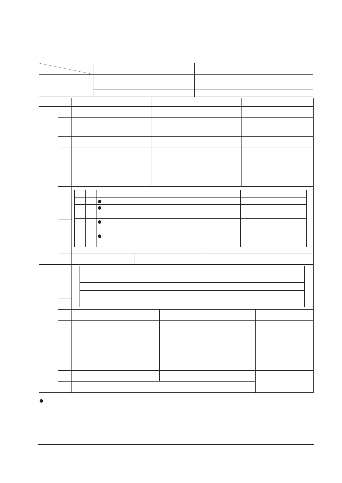
4-2-4 (D) NON-TTX MICOM (SZM-173AR/EA) OPTION BYTE (FOR MIDDLE EAST/AFRICA)
BYTE BIT LOW (0) HIGH (1) Remark
B
Y
T
E
0
D7
D6
TV : NORMAL ZOOM
A/V : NORMAL ZOOM
TV : NORMAL ZOOM 16:9
A/V : NORMAL ZOOM
D5 NOT USED CHILD LOCK ON
D4
CH Up/down functional in the
A/V Mode (SCART Jack)
CH Up/down not functional in the
A/V Model (RCA Jack)
Middle East : HIGH
Africa : LOW
D3 Sound-I System Used Sound-I System Not Used
D
2
D
1
D0 TDA8374A TDA8842 IC201 (ONE-CHIP) OPTION
B
Y
T
E
1
D7
D6
D5 AFT ON (always) AFT OFF after fine tuning
D4
Existing sharpness level (when
using the TDA6108 RGB AMP)
Sharpness level up (when using the
TDA6107Q RGB AMP)
D3 No Auto Power On Auto Power On
D2
NTSC : 25 KHz ( NTSC TAB LE)
PAL : 50 KHz ( PAL TABLE)
NTSC : 25 KHz (NTSC TABLE)
PAL : 27 KHz (NTSC TABLE)
D1
D0
D2 D1 COLOR SYSTEM SOUND SYSTEM
0 0
CK : AUTO (NO OSD ) "?" B/G D/K
0 1
CW : -. RF : AUTO PAL SECAM NT4.43
-. A/V : AUTO PAL SECAM NT4.43 NT3.58
"?" B/G D/K I
1 0
CB : - RF : PAL ONLY
- A/V : AUTO PAL NT4.43 NT3.58
B/G ONLY (NO OSD)
1 1
CS : -. RF : AUTO PAL SECAM NT4.43 NT3.58
-. A/V : AUTO PAL SECAM NT4.43 NT3.58
"?" B/G D/K I
NT-
M
Destination BYTE 0 BYTE 1
MP OPTION
BYTE
Middle East (EA or AR) 7F 58
Africa (EA) 67 D8
D7 D6 LANGUAGE Remark
0 0 - NOT USED
0 1 ENG / ARAB Middle East
1 0 - NOT USED
1 1 ENG / ARAB / FRENCH EA VERSION (Africa ONLY)
Function Required : 1. PICTURE OFF (after 15 minutes) during no signal
2. AUDIO MUTE during no signal.
SCREEN ON/OFF
4. TIMER (CLOCK ON/OFF)
5. (always)
®Ÿ
®Ÿ ®Ÿ
®Ÿ
®Ÿ
®Ÿ ®Ÿ
®Ÿ ®Ÿ
®Ÿ
®Ÿ
®Ÿ
®Ÿ
®Ÿ
®Ÿ
®Ÿ
®Ÿ
®Ÿ
®Ÿ
®Ÿ
®Ÿ
®Ÿ
®Ÿ
®Ÿ
®Ÿ
®Ÿ
®Ÿ
®Ÿ
®Ÿ
®Ÿ
®Ÿ ®Ÿ ®Ÿ
3. BLUE
MUST = LOW
MUST = HIGH
MUST = HIGH
MUST = HIGH
MUST = LOW
MUST = HIGH
CHILD LOCK ON
GAME (Middle East)
7F
5A
Others
GAME
MUST = LOW
Page 22
Alignment and Adjustments
4-8 Samsung Electronics
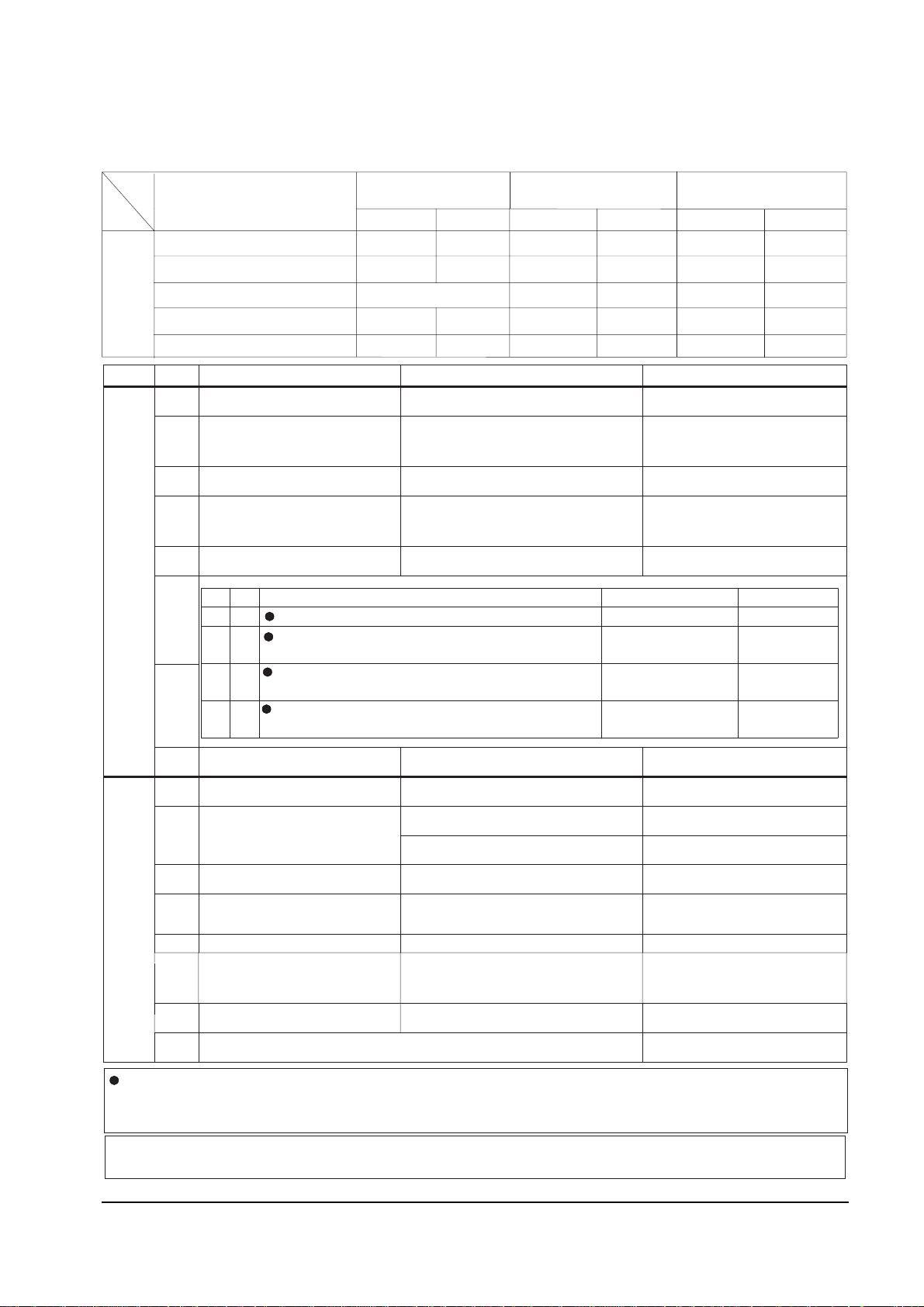
4-2-4 (E) NON-TTX MICOM (SZM-173EV/ET) OPTION BYTE (FOR ASIA)
BYTE BIT LOW (0) HIGH (1) Remark
B
Y
T
E
0
D7 LINE STEREO OFF LINE STEREO ON SZM-173EV (only)
D6
TV : NORMAL ZOOM
A/V : NORMAL ZOOM
TV : NORMAL ZOOM 16:9
A/V : NORMAL ZOOM
D5 MUST = LOW
D4
CH Up/down functional in the
A/V Mode (SCART Jack)
CH Up/down not functional in
the A/V Mode (RCA Jack)
D3 Sound-I System Used Sound-I System Not Used
D2
D1
D0 TDA8374A TDA8842 IC201 (ONE-CHIP) OPTION
B
Y
T
E
1
D7 TV OUT MONITOR OUT
D6 English ONL Y
English/Vietnamese/Indonesian/Malay SZM-173EV
English/Thai SZM-173ET
D5 AFT ON (always) AFT OFF (after fine tuning)
D4
D3 No Auto Power On Auto Power On
D2
D1
D0 MUST = LOW
D2 D1
COLOR SYSTEM SOUND SYSTEM Destination
0 0 CK :AUTO (NO OSD) "?" B/G D/K
0 1
CW : -. RF : AUTO PAL SECAM NT4.43
-. A/V : AUTO PAL SECAM NT4.43 NT3.58
"?" B/G D/K I
1 0
CB : - RF : PAL ONLY
- A/V : AUTO PAL NT4.43 NT3.58
B/G ONLY (NO OSD)
Indonesia/Thailand/
India
1 1
CS: - RF : AUTO PAL SECAM NT4.43 NT3.58
-A/V : AUTO PAL SECAM NT4.43 NT3.58
"?" B/G D/K
I
NT- M
Vietnam
Malaysia
SZM -173ET (16K) : Z90203 WITHOUT LINE STEREO
SZM -173EV (24K) : Z90234 WITH LINE STEREO
Function Required : 1. PICTURE OFF (after 15 minutes) during no signal. 2. AUDIO MUTE during no
signal.
BLUE SCREEN ON/OFF. 4. TIMER (CLOCK ON/OFF).
5. No CHILD LOCK
®Ÿ
®Ÿ
®Ÿ
®Ÿ
®Ÿ
®Ÿ
®Ÿ
®Ÿ
®Ÿ
®Ÿ
®Ÿ
®Ÿ
®
®Ÿ
®Ÿ
®Ÿ
®Ÿ
®Ÿ
®Ÿ
®Ÿ
®Ÿ
®Ÿ
®Ÿ
®Ÿ
®Ÿ
®Ÿ®Ÿ®Ÿ
®Ÿ
®Ÿ
®Ÿ
®Ÿ
3.
®Ÿ
®Ÿ
Existing sharpness level
(when using the TDA6108 RGB AMP)
Sharpness level up (when using the
TDA6107Q RGB AMP)
MUST = HIGH
CLOCK DISPLAY OFF
CLOCK DISPLAY ON Indonesia ONLY : HIGH
MUST = HIGH
BASIC = HIGH
BASIC = HIGH
MUST = LOW
DESTINATION
LINE-STREEO MONO(TV-OUT)
MONO(MONO-OUT)
OPTION
-
BYTE
Vietnam / Malaysia
Indonesia (CB MODEL CLOCK ON)
Thailand (CB MODEL)
India (CB MODEL AFT OFF)
India (CS MODEL AFT OFF)
BYTE 0
BYTE 1
BYTE 0
BYTE 1
BYTE 0
BYTE 1
DF
DF
DD
DD
D8
DA
B8
B8
5F
5D
5D
_
_
_
_
58
5A
58
38
5F
5F
5D
5D
5F B8
D8
DA
D8
NTSC : 25KHz (NTSC TABLE)
PAL : 50KHz (PAL TABLE)
NTSC : 25KHz (NTSC TABLE)
PAL : 27KHz (PAL TABLE)
_
Page 23
Alignment and Adjustments
Samsung Electronics 4-9
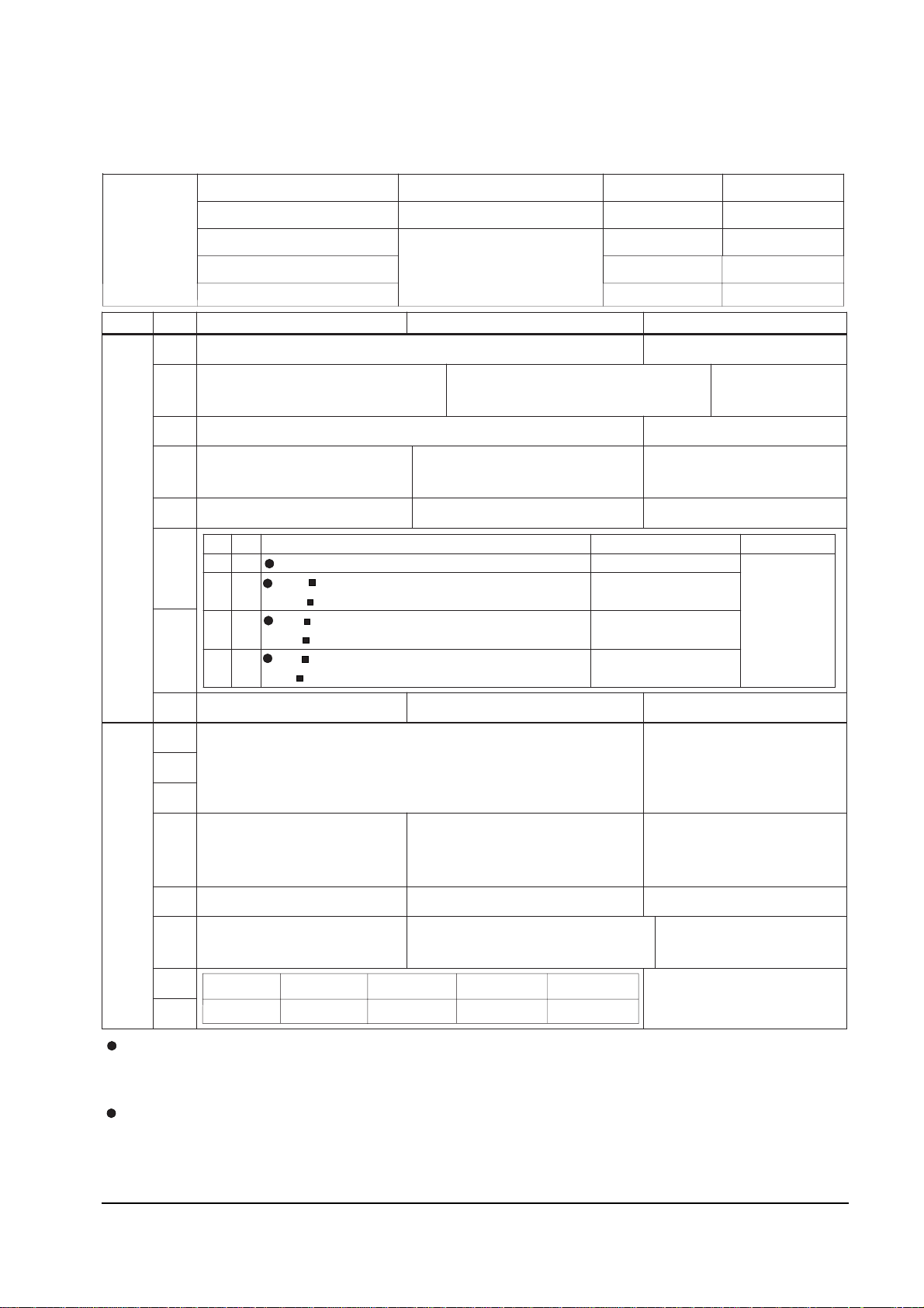
4-2-4 (F) TTX MICOM (SZM-175EA/EP) OPTION BYTE (FOR MIDDLE EAST ASIA)
BYTE BIT LOW (0) HIGH (1) Application MICOM
B
Y
T
E
0
D7 NOT USED ALL = LOW
D6
TV : NORMAL ZOOM 16:9
A/V : NORMAL ZOOM
TV : NORMAL ZOOM 16:9
A/V : NORMAL ZOOM 16:9
MUST = LOW
D5 NOT USED ALL = LOW
D4
CH Up/down functional in
the A/V Mode (SCART Jack)
CH Up/down not functional in
the A/V Mode (RCA Jack)
Africa : SCART
Others : RCA
D3 Sound-I System Used Sound-I System Not Used
D2
D1
D0 TDA8374A TDA8842
B
Y
T
E
1
D7
NOT USED ALL (FIX = LOW)D6
D5
D4
Existing sharpness level
(when using the TDA6108
RGB AMP)
Sharpness level up
(when using the TDA6107Q RGB
AMP)
ALL (BASIC = HIGH)
TEST Unnecessary
D3 No Auto Power On Auto Power On ALL (BASIC = HIGH)
D2
NTSC : 25 KHz (NTSC TABLE)
PAL : 50 KHz (PAL TABLE)
NTSC : 25 KHz (NTSC TABLE)
PAL : 27 KHz (NTSC TABLE)
D1
MUST = HIGH
D0
D2 D1
COLOR SYSTEM SOUND
SYSTE M R emark
0 0 CK : AUTO (NO OSD) B/G D/K
No sou nd
systemin the A
/V
M O D E
0 1
CW : RF : AUTO PAL SECAM NT4.43
A/V : AUTO PAL SECAM NT4.43 NT3.58
B/G D/K I
1 0
CB : RF : PAL ONLY (NO OSD)
A/V : AUTO PAL NT4.43 NT3.58
B/G ONLY (NO OSD)
1 1
CS : RF : AUTO PAL SECAM NT4.43 NT3.58
A/V : AUTO PAL SECAM NT4.43 NT3.58
B/G D/K
I
NT M
Function Required : 1. PICTURE OFF (after 15 minutes) during no signal
2. AUDIO MUTE (during no signal)
3. No BLUE
SCREEN
4. No TIMER
5. No CHILD LOCK
OSD language by micom
1. Persian (for Iran) : SPM-175EP : English/Persian (Iranian)
2. Arab (Middle East, Africa) : SPM-175EA : English/French/Arabian
MP
OPTION
BYTE
Destination Application MICOM BYTE0 BYTE1
Iran (Persian TTX) SPM-175EP 1F 1B
Middle East (except Iran)
SPM-175EA
1F 1B
Africa 07
®Ÿ
®Ÿ
®Ÿ
®Ÿ
®Ÿ
®Ÿ
®Ÿ
®Ÿ ®Ÿ
®Ÿ
®Ÿ ®Ÿ ®Ÿ ®Ÿ
®Ÿ
®Ÿ ®Ÿ
®Ÿ
®Ÿ
®Ÿ
®Ÿ
®Ÿ
®Ÿ
®Ÿ ®Ÿ
®Ÿ ®Ÿ
®Ÿ ®Ÿ
®Ÿ ®Ÿ ®Ÿ ®Ÿ
®Ÿ
®Ÿ
-
Ÿ
-
"?"
"?"
®Ÿ
"?"
D1 D0
00
01
10 11
B/G
D/K
I
?
®Ÿ
®Ÿ
Singapore
17
1B
1B
Page 24
Alignment and Adjustments
4-10 Samsung Electronics
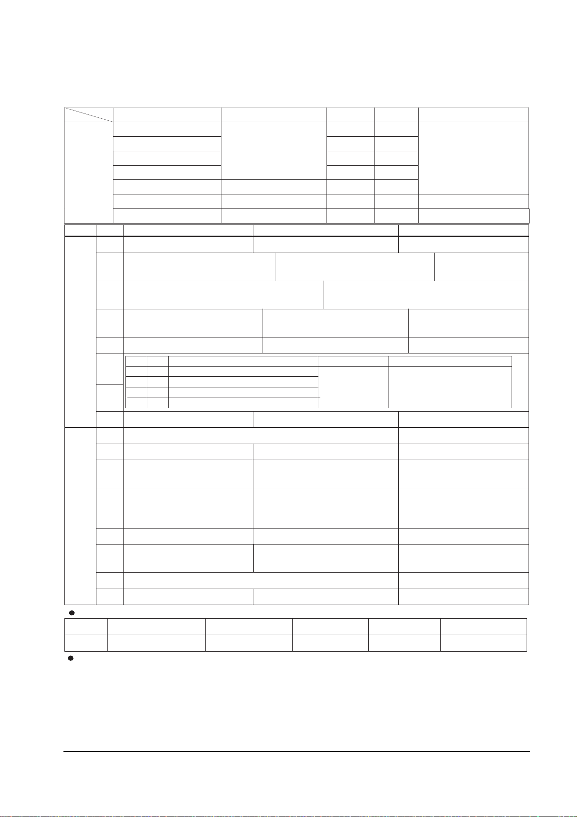
4-2-4 (G) TTX MICOM (SPM-175EE/ER/EG/EU) OPTION BYTE (FOR EUROPE)
BYTE BIT LOW(0) HIGH(1) Remark
B
Y
T
E
0
D7 3 BAND UHF DNLY (UK only)
D6
TV : NORMAL ZOOM 16:9
A/V : NORMAL ZOOM
TV : NORMAL ZOOM 16:9
A/V : NORMAL ZOOM 16:9
D5
<POLAND OPTIO N>
R913 : 680 added. J901 : Delete
D4
CH Up/Down functional in the
A/V Mode (SCART Jack)
CH Up/Down not functional in
the A/V Model (RCA Jack)
MUST = LOW
D3 P-STD NORMAL P-STD MAX MUST = LOW
D2
D1
D0 TDA8374A TDA8842
B
Y
T
E
1
D7 NOT USED
D6 PAL/SECAM SECAM - L HIGH (CF only)
D5
English/German/French/Dutch/
Italian/Spanish/Swedish
English/Croatian/Romanian/
Hungarian/Polish/Czech
This bit is only applied to
SPM-175EE
D4
Existing sharpness level
(when using the TDA6108
RGB AMP)
Sharpness level up
(when using the TDA6107Q AMP)
TEST Unnecessary
D3 No Auto Power On Auto Power On
D2
NTSC : 25KHz (NTSC TABLE )
PAL : 50KHz (PAL TABLE)
NTSC : 25KHz (NTSC TABLE )
PAL : 27KHz (NTSC TABLE)
ALL (RF VOL. CURVE) BASIC = LOW
D1 MUST = LOW
D0
D2 D1
SOUND SYSTEM COLOR SYSTEM Remark
0 0 "?"
B/G D/K : CK MODEL
AUTO
(NO OSD)
No SOUND SYSTEM
in the A/V Mode
0 1 I ONLY (NO OSD) : CI,CII MODEL
1 0 B/G ONLY (NO OSD): CB,CX MODEL
1 1 NOT USED
Destination Application MICOM BYTE 0 BYTE 1 LANGUAGE
MP
OPTION
BYTE
United Kingdom (CI)
SPM-175EE
83 18
See BYTE 1 D5
Other Western Europe (CB) 05 18
Eastern Europe (CK) 01 38
France/Swiss SPM-175EU 05 58
Yugo/Greece
SPM-175EG 05 18 English/Yugo/Greek
Russia/Bulgaria SPM-175ER 01 19 English/Russian/Bulgarian
P-STD Classification (CON/BRI/SHRP/COL)
D3 BIT STANDARD MODE DYNAMIC MODE MOVIE MODE MILD MODE CUSTOM MODE
0 90/50/50/50 100/50/50/50 75/55/50/50 60/50/50/50 90/55/25/50
Function Required :1. PICTURE OFF (after 15 minutes) during no signal. 2. AUDIO MUTE (during no
3. No BLUE SCREEN. 4. No TIMER (CLOCK /OFF). 5. No CHILD LOCK
®Ÿ
®Ÿ
®Ÿ
®Ÿ
®Ÿ
®Ÿ
®Ÿ
®Ÿ «Ÿ
®Ÿ
signal).
MUST = LOW
ALL BASIC = HIGH
ALL BASIC = HIGH
Ireland (CII) 03
18
FIX = LOW
B/G
D/K
175ER is only applied (Others = LOW)
W
Page 25

4-3 Other Adjustments
4-3-1 General
1. Usually, a color TV needs only slight touchup adjustment upon installation. Check the
basic characteristics such as height, horizontal
and vertical sync and focus.
2. The picture should have good black and white
details. There should be no objectionable
color shading; if color shading is present, perform the purity and convergence adjustments
described below.
3. Use the specified test equipment or its equivalent.
4. Correct impedance matching is essential.
5. Avoid overload. Excessive signal from a sweep
generator might overload the front-end of the
TV. When inserting signal markers, do not
allow the marker generator to distort test
results.
6. Connect the TV only to an AC power source
with voltage and frequency as specified on the
backcover nameplate.
7. Do not attempt to connect or disconnect any
wires while the TV is turned on. Make sure
that the power cord is disconnected before
replacing any parts.
8. To protect against shock hazard, use an isolation transformer.
4-3-2 Automatic Degaussing
A degaussing coil is mounted around the picture tube, so that external degaussing after
moving the TV should be unnecessary. But
the receiver must be properly degaussed upon
installation.
The degaussing coil operates for about 1 second after the power is switched ON. If the set
has been moved or turned in a different direction, disconnect its AC power for at least 30
minutes.
If the chassis or parts of the cabinet become
magnetized, poor color purity will result. If
this happens, use an external degaussing coil.
Slowly move the degaussing coil around the
faceplate of the picture tube and the sides and
front of the receiver. Slowly withdraw the coil
to a distance of about 6 feet before removing
power.
4-2-5 RESET
The Reset Mode is used during factory inspection.
Function Reset:
1. Channels Add/Erase
2. Sort Non
3. System Auto
4. Timer off
5. Blue Screen off
6. Child Lock off
7. Picture standard
8. Volume 10
9. CH. Skip Erased
Alignment and Adjustments
Samsung Electronics 4-11
Page 26

4-3-3 High Voltage Check
CAUTION: There is no high voltage adjustment on this chassis.
The B+ power supply must be set to +125 volts (Full color bar input
and normal picture level).
1. Connect a digital voltmeter to the second
anode of the picture tube.
2. Turn on the TV. Set the Brightness and
Contrast controls to minimum (zero beam current).
3. The high voltage should not exceed 27.5KV.
4. Adjust the Brightness and contrast controls to
both extremes. Ensure that the high voltage
does not exceed 27.5KV under any conditions.
4-3-4 FOCUS Adjustment
1. Input a black and white signal.
2. Adjust the tuning control for the clearest pic-
ture.
3. Adjust the FOCUS control for well defined
scanning lines in the center area of the screen.
4-3-5 Cathode Voltage Adjustment
(Screen Adjustment)
1. Connect CRT socket pin GK to an oscilloscope
probe.
2. Input a gray scale pattern. (Use a pattern gen-
erator, PM5518)
3. Use the P mode key (on the remote control)
for the STANDARD picture.
4. Adjust the Screen VR (on the FBT) so that the
voltage on the oscilloscope becomes 130+2.5V
(See Fig. 4-1).
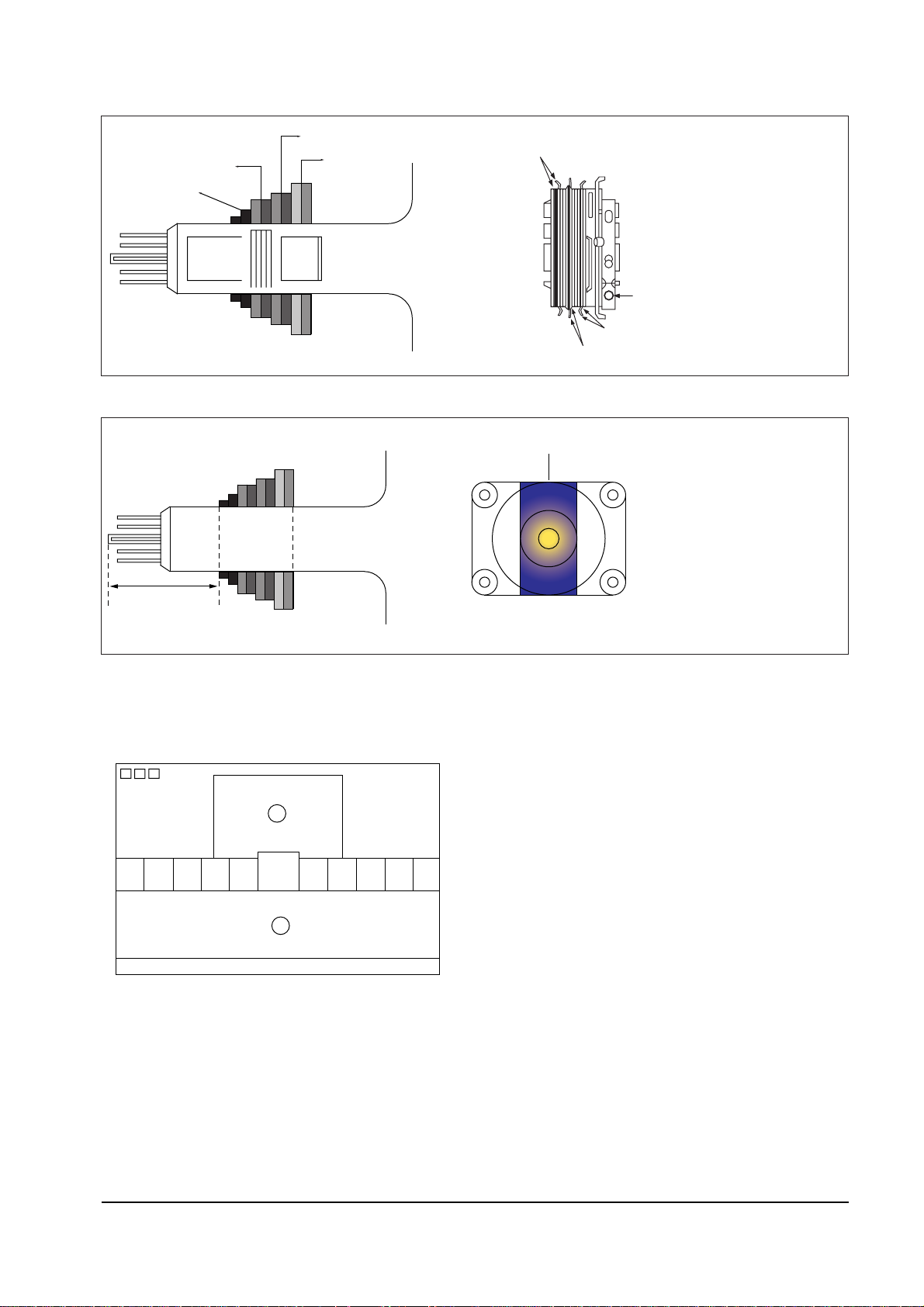
4-3-6 Purity Adjustment
1. Warm up the receiver for at least 20 minutes.
2. Plug in the CRT deflection yoke and tighten
the clamp screw.
3. Plug the convergence yoke into the CRT and
set in as shown in Fig. 4-2.
4. Input a black and white signal.
5. Fully demagnetize the receiver by applying an
external degaussing coil.
6. Turn the CONTRAST and BRIGHTNESS controls to maximum.
7. Loosen the clamp screw holding the yoke.
Slide the yoke backward or forward to provide vertical green belt. (Fig. 4-3).
8. Tighten the convergence yoke.
9. Slowly move the deflection yoke forward,
and adjust for the best overall green screen.
10. Temporarily tighten the deflection yoke.
11. Produce blue and red rasters by adjusting the
low-light controls. Check for good purity in
each field.
12. Tighten the deflection yoke.
Alignment and Adjustments
4-12 Samsung Electronics
Fig. 4-1
130 2.5V
+
_
GND
14, 16" :120 2.5V
20, 21" : 130 2.5V
+
_
+
_
_
Page 27
4-3-7 White Balance Adjustment
Alignment and Adjustments
Samsung Electronics 4-13
Fig. 4-2 Convergence Magnet Assembly
4 Pole Magnet
6 Pole Magnet
2 Pole Magnet
Clamper
Screw
2 POLE
PURITY
YOKE
CLAMP
SCREW
6 POLE
CONVERGENCE
4 POLE
CONVERGENCE
ADJUST THE ANGLE
(VERTICAL LINES)
Fig. 4-3 Center Convergence Adjustment
31m/m
Vertical Green Belt
Fig. 4-4
1
2
(a) Set up
1. Warm up the TV for at least 30 minutes in the
Aging Mode (OSD White). This mode is displayed by entering the following sequence:
SLEEP ®FACTORY ® FACTORY
2. Input a Toshiba pattern.
(b) Low-Light Adjustment
1. Set SBT to 1.3 ± 0.2 fL in the Factory Service
Mode with using CA100. See Fig. 4-4 ➁.
2. Adjust RG,BG so that the levels are suitable to
each local area.
(c) High-Light Adjustment
1. Set SCT to 55 FL (20Ó. 21Ó), 65 FL(14Ó.16Ó) in
the Factory Service Mode with using CA100.
See Fig. 4-4 ①.
Page 28
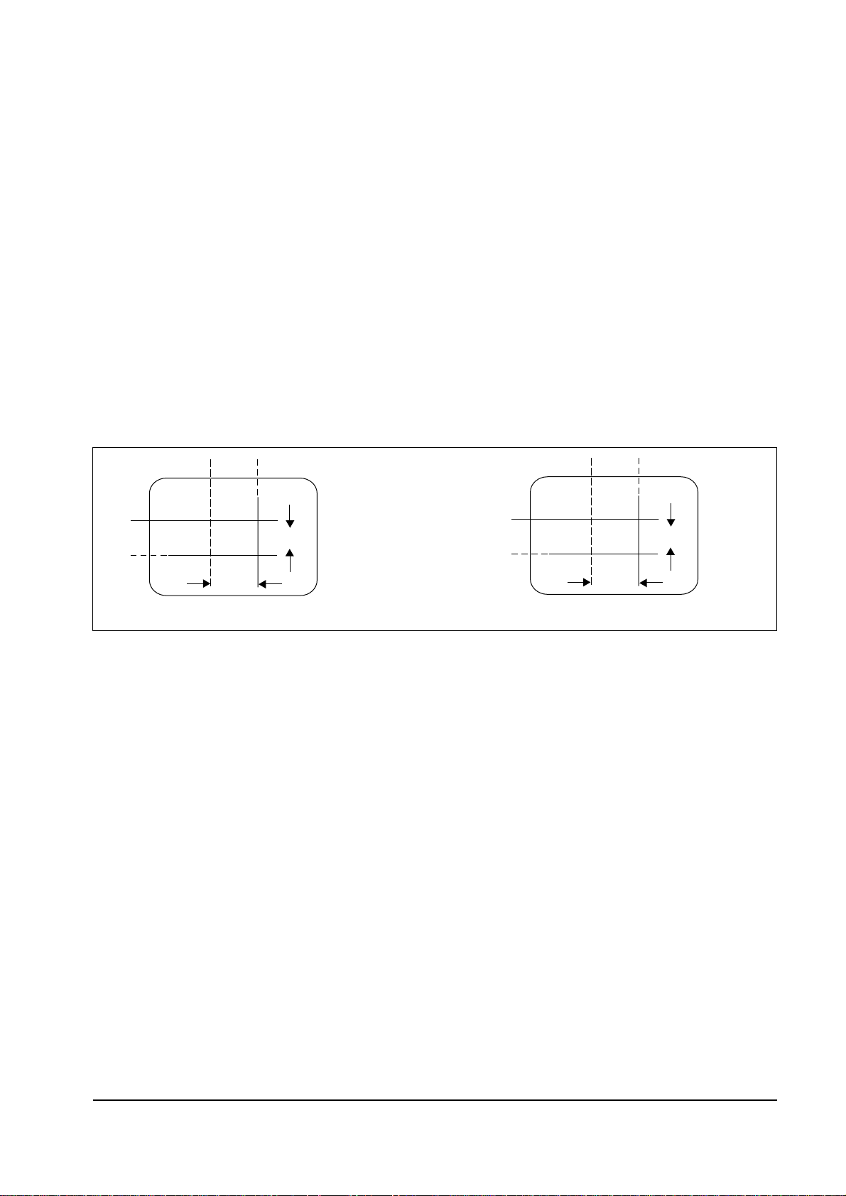
4-3-8 Center Convergence Adjustment
1. Warm up the receiver for at least 20 minutes.
2. Adjust the two tabs of the 4 pole magnets to
change the angle between them. Superimpose
the red and blue vertical lines in the center
area of the screen.
3. Adjust the Brightness and Contrast controls
for a well defined picture.
4. Adjust the two-tab pairs of the 4 pole magnets, and change the angle between them.
Superimpose the red and the blue vertical
lines in the center area of the screen.
5. Turn the both tabs at the same time, keeping
the angle constant, and superimpose the red
and blue horizontal line in the center of the
screen.
6. Adjust the two-tab pairs of the 6-pole magnets
to superimpose the red and blue line onto the
green. (Changing the angle affects the vertical
lines, and rotating both magnets affects the
horizontal lines.)
7. Repeat adjustments 2~6, if necessary.
8. Since the 4-pole magnets and 6-pole magnets
interact, the dot movement is complex
(Fig. 4-5).
Alignment and Adjustments
4-14 Samsung Electronics
4-3-9 VCO Adjustment
Fig. 4-5 Center Convergence Adjustment
RED
BLUE
BLUE
RED
4-Pole Magnet Movement
GREEN
RED/BLUE
RED/BLUE
GREEN
6-Pole Magnet Movement
Set the vco data to 80 (Factory Mode).
NOTE : For SZM-173EW and SPM-175E (Western Europe remote control), set the VCO data to 1.
Page 29
4-3-10 RF AGC Adjustment
Set the AGC data to 14 (Factory Mode).
4-3-11 Sub-Color Adjustment
Set SCR data to 10 (Factory Mode).
4-3-12 Geometry Adjustment
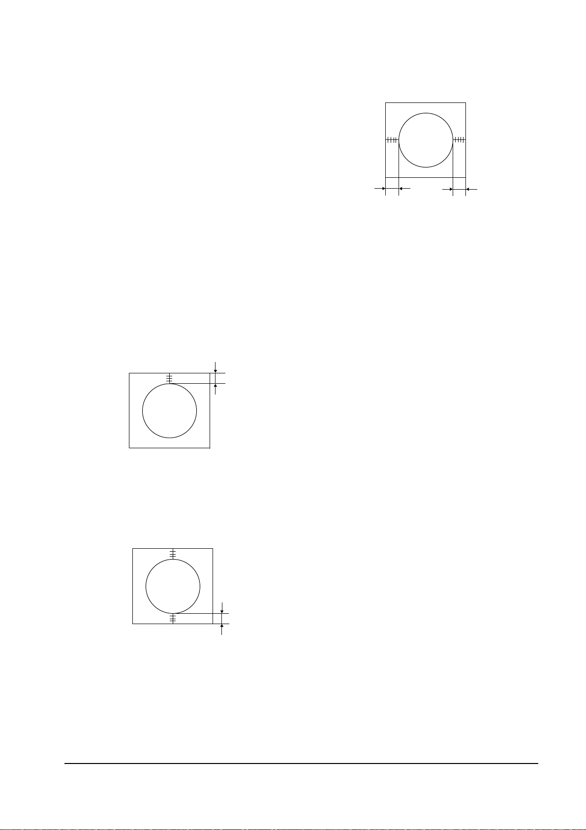
SC ®PVA®PVS® PSL ®PHS
1. Input a lion head pattern (in the PAL channel).
2. Set the SC (S-Correction) as follows : 12 (21Ó),
10 (20Ó), 0 (14Ó,16Ó) and PVA 40 so that the
lion head circle becomes oval.
3. Adjust with PVS (Vertical shift) so that the top
margin of the picture is 4.
Fig. 4-7
4. Adjust with PSL (Vertical-Slope) so that the
bottom margin of the picture is 4.
Fig. 4-8
5. Adjust with PHS (Horizontal Shift) so that the
lion-head pattern and CRT centers are aligned.
Fig. 4-9
6. Adjust PHS (using the width coil) so that the
left and right margins of the picture are 5.
Alignment and Adjustments
Samsung Electronics 4-15
4
5
5
4
Page 30

MEMO
4-16 Samsung Electronics
Page 31
Troubleshooting
Samsung Electronics 5-1
5. Troubleshooting
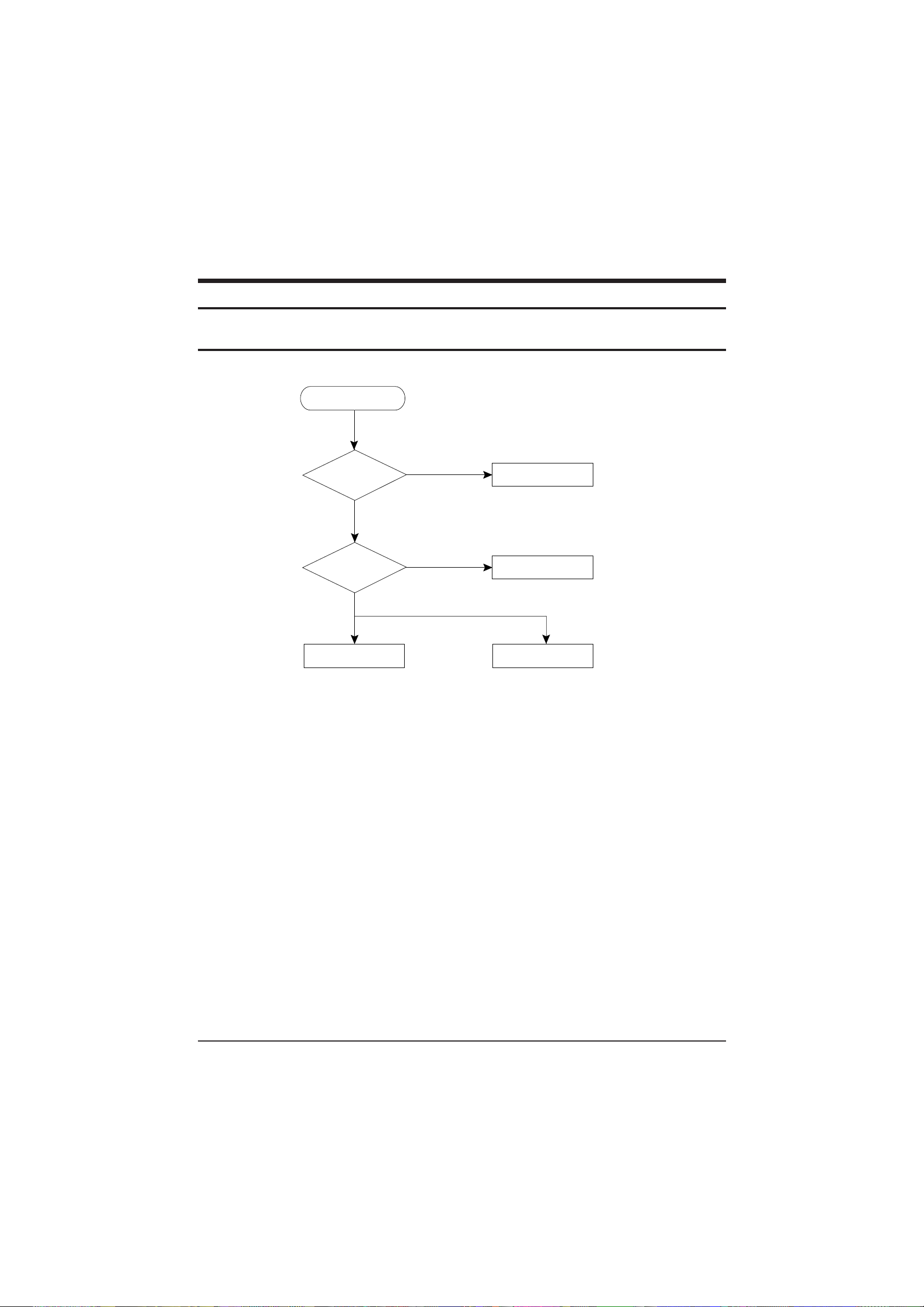
5-1 No Video (Raster On, No Sound)
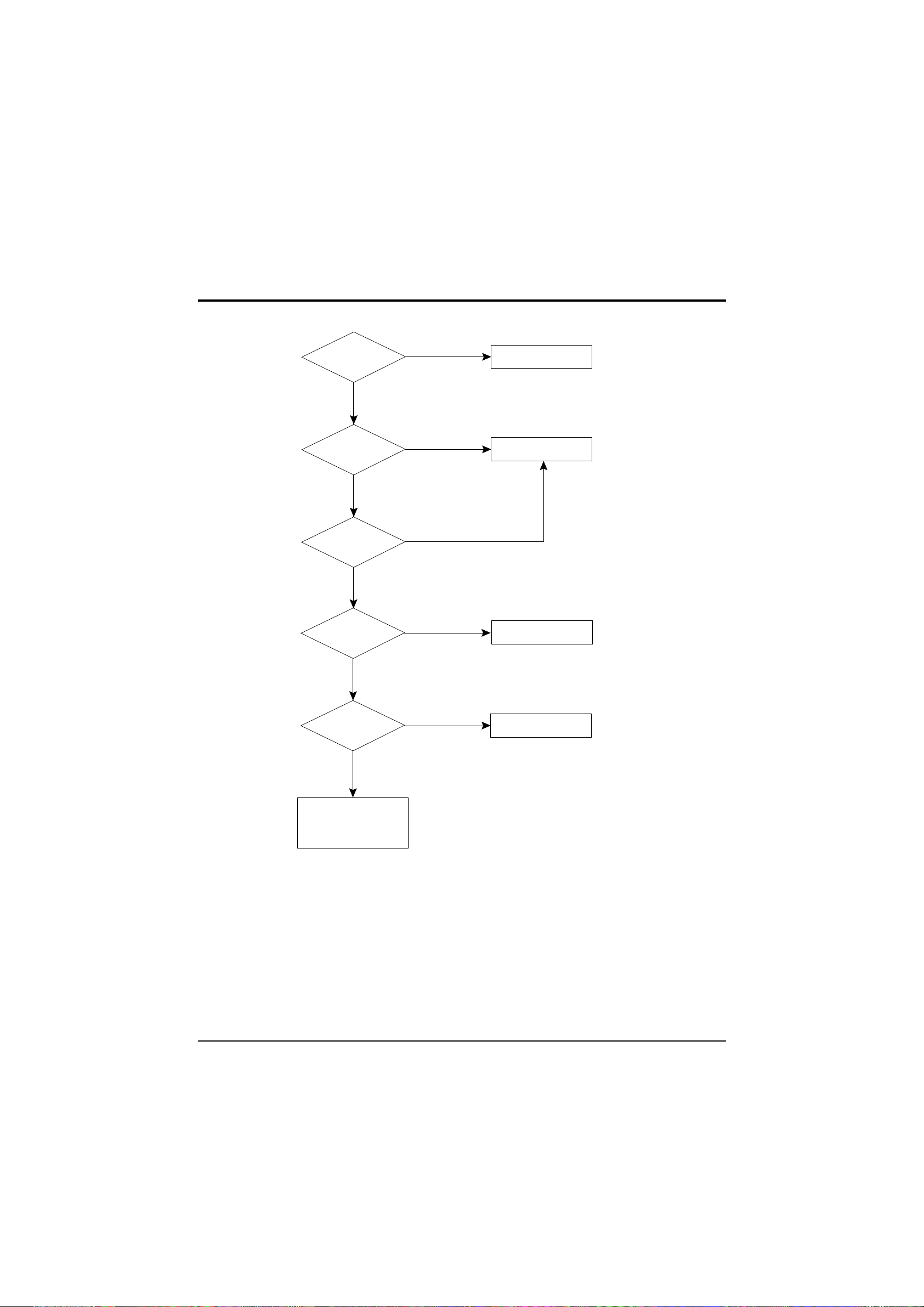
Yes
No
Open the IF Pin of Tuner
Check/Replace
TU01,
No
Measure the
Voltage of Each Pin
of TU01
Check IC901
Pins 39, 40
See "No Video"
(Sound OK)
See "No Sound"
(Video OK)
Check/Replace
IC901, IC201
Yes
Page 32
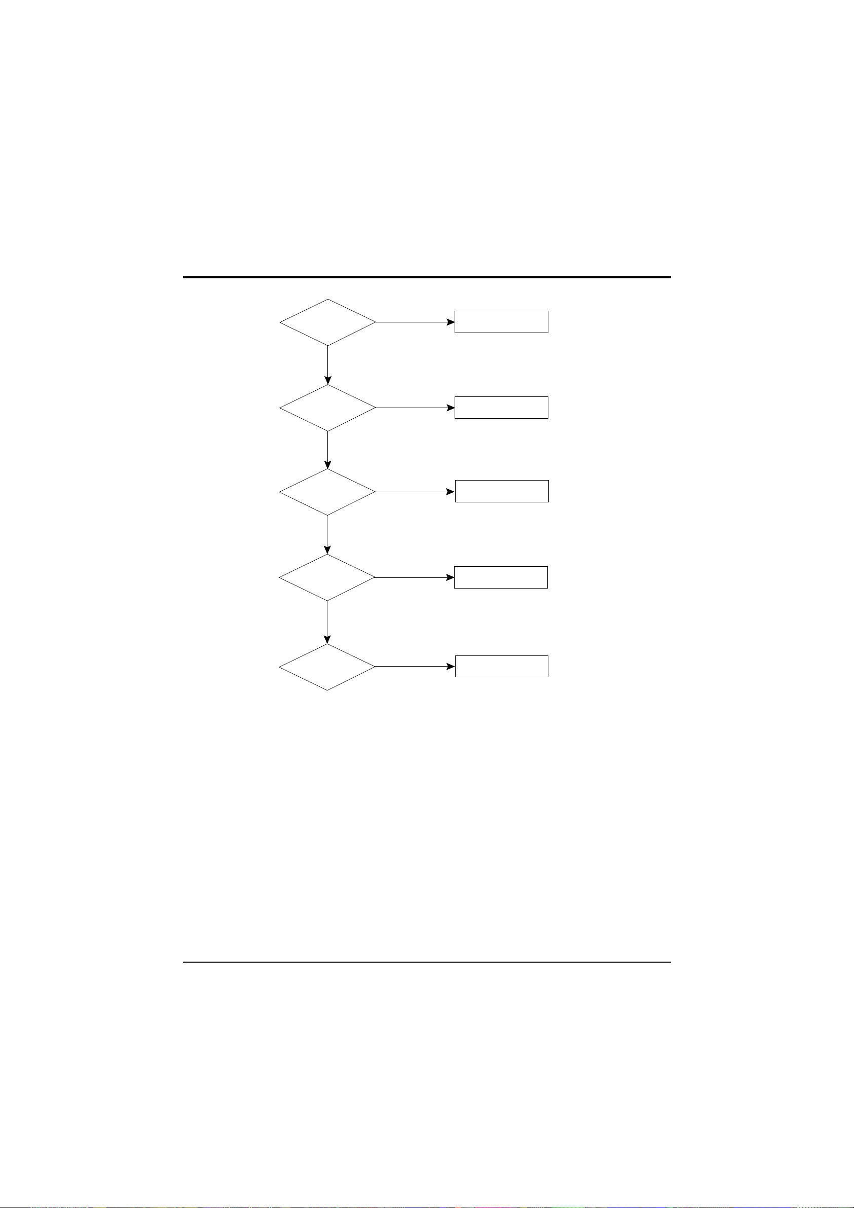
5-2 No Power
Troubleshooting
5-2 Samsung Electronics
Yes
No
No
Yes
No
No
No
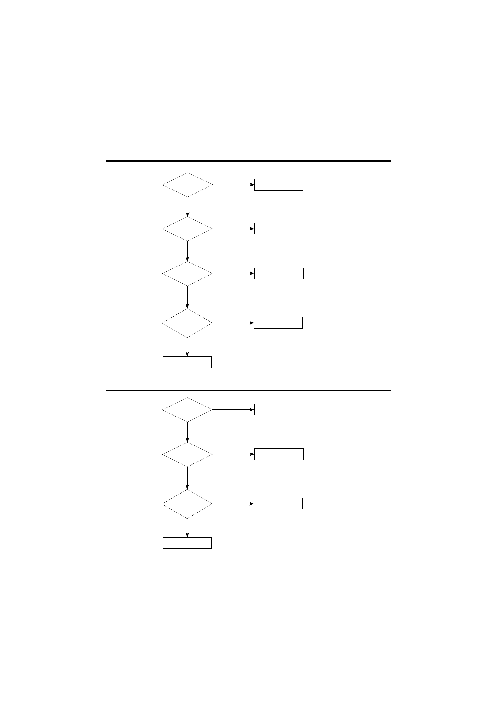
Check the 125V,
13.0V B+ Lines
Check IC802
Pin 9 (5V)
Check/Replace
IC801, D801, F802
Check/Replace
IC802 (KA7630)
Check IC901
Pin 18 ; Stand-by : 0V
Normal : 5V
Check/Replace
IC901
Check IC901
Pin 16 (4V).
Check/Replace
IC901, (µ-com).
Check IC201,
Pin 40 (H-out)
Check/Replace
IC201, Q401, Q402.
Page 33
5-3 No Video (Sound OK)
Troubleshooting
Samsung Electronics 5-3
Yes
No
No
Yes
No
No
Check IC201
Pin 6 (CVBS)
Check/Replace
IC201
Check IC201
Pins 19, 20, 21
Check IC201
pin 27 (Y-IN)
Check/Replace
IC201, Q203
Check IC501
on the CRT PCB
Check/Replace
IC501
Check/Replace
R417, R505 (HEATER 6.3Vrms)
D503 (CRT G1 pin)
CRT, V999
Yes
No
Check IC201
Pin 12,37 (8V)
Check/Replace
IC802 KA7630
Page 34
Troubleshooting
5-4 Samsung Electronics
5-4 No Sound (Video OK)
No
No
No
Check/Replace
A/V Front assembly.
Check IC201
Pin 15 (Sound Out)
Check/Replace
IC201
Check IC602
Pin 4 (B+ 10-12.5V)
Check/Replace
Q903, Q907
Check IC602
Check/Replace
IC602
Check IC602
Pins 1,7 (0V)
Check/Replace
R812, R813
Yes
Yes
No
Yes
Yes
5-5 No TTX
No
No
See No Video
Check IC901
Pin 31,32,33,34,35
Check/Replace
QT02, IC901
Check IC201
Pin 23, 24, 25, 26
Check/Replace
IC201
Check IC901
Pins 24
Check/Replace
IC901
Yes
No
Yes
Yes
Page 35
Exploded View & Parts List
Samsung Electronics 6-1
6. Exploded View & Parts List
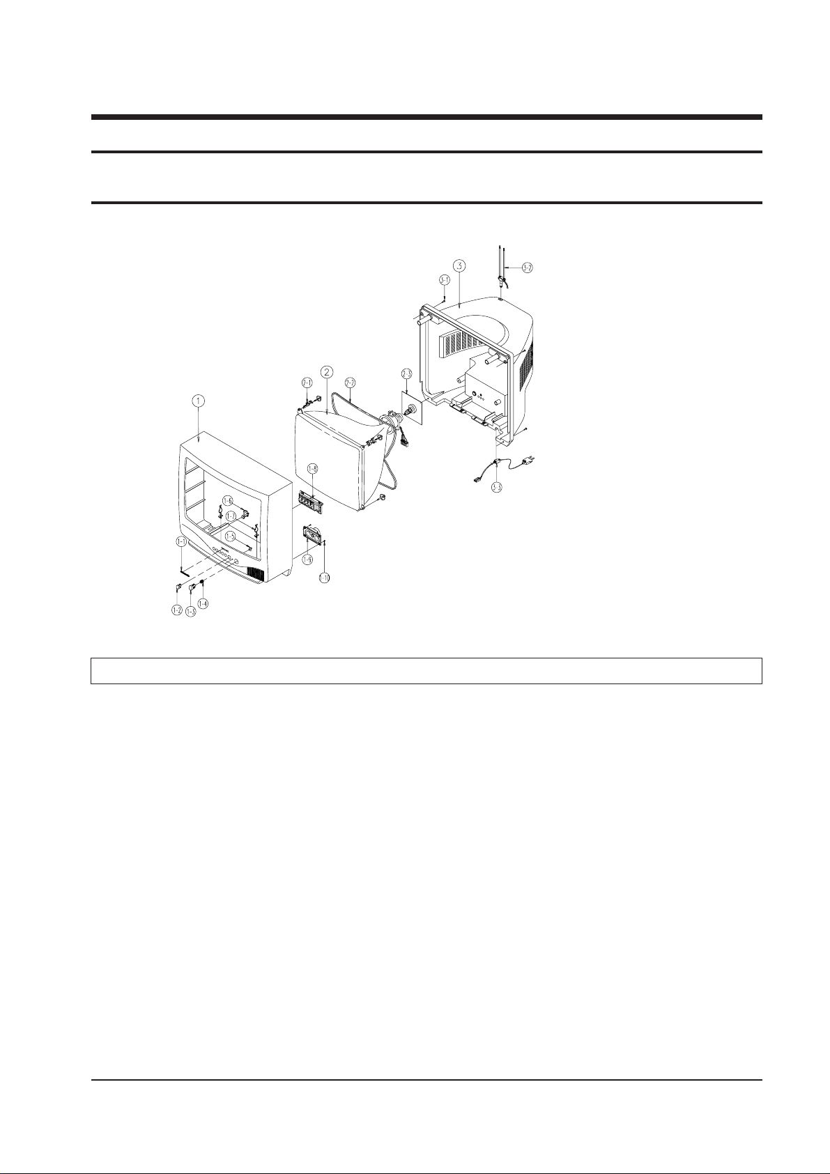
6-1 CK331FVR5X/BWT
No Code No Description Specification Q’ty Remark
1 AA91-10358G ASSY-CABINET,FRONT -,CK331FVR,BK708P BWT TVI NEW, 1
AA64-31095K CABINET-FRONT -,CK331FVR,BK708P BWT TVI NEW, 1
1-1 AA64-70009F BADGE-BRAND AL,SS R800 22,SILVER,L40,-,-,- 1
1-2 AA64-40450A WINDOW-RMC -,501F,-,ABS,HB,LG-41338,- 1
1-3 AA64-10704C KNOB-POWER -,501F,-,ABS,HB,BLK 1
1-4 AA61-60003Q SPRING-CS -,SUS304,0.5,OD8,H10,N5,-,-,- 1
1-5 AA64-40451A INDICATOR-LED -,501F,-,ABS,HB,-,- 1
1-6 AA61-40007A STOPPER-PCB 5038.5368,ABS HB,NTR,-,-,- 1
1-7 AA65-30105A CLAMP-WIRE NYLON 66,V2,NTR,15MM,ALL MODEL 1
1-8 AA64-10705A KNOB-CONTROL -,501F,-,ABS,HB,BLK 1
1-9 3001-000275 SPEAKER 2.5W,16ohm,90dB,105Hz 1
1-10 6002-000514 SCREW-TAPPING RH,+,2,M4,L15,ZPC(BLK),SWRCH18 2
2 AA03-10001D CRT-COLOR -,A34KQV42X,+380MG,14,90DEG,5 1
2-1 AA65-30106A CLAMP-D,COIL NYLON 66,V2,NTR,-,14 INCH,- 2
2-2 AA27-20003U COIL-DEGAUSSING -,14,16.4ohm,75T,890mm,D 1
2-3 3704-001089 SOCKET-CRT 7P,22.5PI,12PI,SN,- 1
3 AA64-31096B CABINET-BACK -,331F,-,HIPS,V2,BLK,-,- 1
3-1 6002-000514 SCREW-TAPPING RH,+,2,M4,L15,ZPC(BLK),SWRCH18 4
3-2 AA42-10001V ANT-ROD -,3S,620mm,BRN,UL/CSA 1
3-3 AA61-20284A HOLDER -,P-CORD,PP,VO,BLK,KE-002 1
Page 36
Electric Parts List
Samsung Electronics 7-1
ASSY-PCB,MAIN(OPT)
BUYER : SRSC
* AA94-00408AASSY-PCB,MAIN(OPT);CK501FVR5S/NWT,S15A,N-RUSSIA,C307 2305-000708 C-FILM,MPEF;150nF,5%,100V,TP,16.5x10.3x5.7
C409 2306-000253 C-FILM,MPPF;7.2nF,5%,1.6KV,TP,28.5x18.5x12
C410 2201-000406 C-CERAMIC,DISC;270pF,10%,2KV,Y5P,TP,8x6,7.5
C416 2306-000195 C-FILM,MPPF;360nF,5%,400V,TP,26x19x11.5,20
C916 2301-000445 C-FILM,PEF;4.7nF,5%,50V,TP,5.5x7x3mm,5mm
CN501 AA39-20109BLEAD-CONNECTOR,ASSY;-,YBNH025-08,S,8P,500,1007#26
CN802 AA27-20003YCOIL-DEGAUSSING;-,20,15.2ohm,28T,L2170,E
L401 AA27-30001BCOIL-LINEARITY;-,195uH,QIC1010,PI0.4,4.5x21.5
R302 2008-001033 R-FUSIBLE(S);10ohm,5%,2W,AF,TP,3.9x10mm
R305 2004-001370 R-METAL(S);1.3ohm,1%,1/2W,AA,TP,2.4x6.4mm
R405 2001-001410 R-CARBON(S);43OHM,5%,1/2W,AA,TP,R417 2008-000265 R-FUSIBLE(S);1ohm,5%,2W,AA,TP,3.9x10mm
R501H 2002-001008 R-COMPOSITION;1.8Kohm,5%,1/2W,AA,TP,3.7x9mm
R502H 2002-001008 R-COMPOSITION;1.8Kohm,5%,1/2W,AA,TP,3.7x9mm
R505 2008-001011 R-FUSIBLE(S);0.18ohm,10%,2W,AF,TP,3.9x10mm
R611 2001-000577 R-CARBON;2KOHM,5%,1/8W,AA,TP,R814 2008-000267 R-FUSIBLE(S);2.4ohm,5%,2W,AA,TP,3.9x10mm
R815 2008-000267 R-FUSIBLE(S);2.4ohm,5%,2W,AA,TP,3.9x10mm
T444 AA26-30001Y TRANS-FLYBACK;-,FSV-20A001,20,125V
V999 3704-001090 SOCKET-CRT;9P,15.24PI,26.5PI,SN,-
ASSY-CRT
AA03-10029WCRT-COLOR;-,A48KRD82X(H),+380mG,20,90de
AA27-00002AMAGNET-CONVERGENCE;-,JH291-SC-OB,29.1MM
AA27-50004WDEFLECTION-YOKE;-,DSE-1992LL(1H),20’/A48KRD82X
ASSY-SPEAKER
3001-000003 SPEAKER;3W,16ohm,88+-2dB,180+-36Hz
AA39-20501CLEAD CONNECTOR-ASSY;-,67096-003,REC,3(2)P,700mm,10
ASSY-ACCESSORY
AA68-11289AMANUAL-USERS;S15A,N-RUSSIA,W/O TTX,B5,W/P 1
ASSY-CABINET;501F,CK501FVR5S/NWT
* AA91-10389C ASSY-CABINET,FRONT;DP,CK501FVR,BK708P MLN TVI (SPK)
AA64-31093MCABINET-FRONT;-,CK501FVR,BK708P BWT TVI,HIPS
AA64-31218BCABINET-BACK;DP,501F,AA64-31094B,-,V2,-,-,-
AA64-10759AKNOB-CONTROL;DP,501F,AA64-10705A,-,-,CRT+CF AA60-10050QSCREW-ASSY;WC,HH,+,M5,L26.5,SWRCH18A,ZPC(
D-COIL AA65-30107ACLAMP-D,COIL;NYLON 66,V2,NTR,-,20~22 INCH,-
AA61-40053ASTOPPER-PCB;ALL MODEL,HIPS HB,WHT,HB,-,-
AA64-70015ABADGE-BRAND;AL,SS R2000 22,SILVER,L45,-,-,
SPK+CF 6002-000514 SCREW-TAPPING;RH,+,2,M4,L15,ZPC(BLK),SWRCH18
7. Electric Parts List
7-1 CK501FVR5S/NWT (CK331FVR5X AND CK501FVR5S Dissimilar Parts)
Loc. No. Code No. Description ; Specification Remark Loc. No. Code No. Description ; Specification Remark
!!!
!
Page 37

ASSY-PCB,MAIN(OPT)
BUYER : SRSC
* AA94-10136E ASSY-PCB,MAIN(OPT);CK331FVR5X/BWT,S15A,RUSSIA,* AA94-00404AASSY-PCB,MAIN(OPT);CK331FVR5S/NWT,S15A,N-RUSSIA,* AA94-00418AASSY-PCB,MAIN(OPT);CK331FVR5X/VWT,S15A,LITHUANIA
C101 2401-000030 C-AL;22uF,20%,25V,GP,TP,5x11,5
C102 2401-001082 C-AL;330nF,20%,50V,GP,TP,5x11,5
C103 2401-001363 C-AL;470uF,20%,16V,GP,TP,10x12.5,5
C201 2306-000122 C-FILM,MPPF;100nF,5%,50V,TP,7.3x4.0x5.0mm,
C202 2401-001840 C-AL;100uF,20%,16V,GP,TP,6.3x11,5
C203 2401-000660 C-AL;2.2uF,20%,50V,GP,TP,5x11,5
C204 2401-000603 C-AL;1uF,20%,50V,GP,TP,5x11,5
C205 2305-000411 C-FILM,MPEF;470nF,5%,50V,TP,7.3x4.8x5.5mm,
C206 2305-000411 C-FILM,MPEF;470nF,5%,50V,TP,7.3x4.8x5.5mm,
C207 2305-000196 C-FILM,MPEF;150nF,5%,63V,TP,-,5mm
C208 2401-000027 C-AL;4.7uF,20%,50V,GP,TP,5x11,5
C209 2202-000849 C-CERAMIC,MLC-AXIAL;18pF,5%,50V,CH,TP,3.5x1.9,C210 2301-000445 C-FILM,PEF;4.7nF,5%,50V,TP,5.5x7x3mm,5mm
C211 2305-000665 C-FILM,MPEF;100nF,5%,63V,TP,7.5x4.0x5.0mm,
C212 2202-000796 C-CERAMIC,MLC-AXIAL;1NF,10%,50V,Y5P,TP,3.5X1.9MM,C213 2201-000273 C-CERAMIC,DISC;18pF,5%,50V,CH,TP,5x3mm,5
C214 2301-000356 C-FILM,PEF;47nF,5%,50V,TP,7.5x4.0x6.5,5mm
C215 2301-000383 C-FILM,PEF;10nF,5%,50V,TP,6x7x3.2mm,5mm
C216 2305-000289 C-FILM,MPEF;220nF,5%,63V,TP,-,5mm
C217 2301-000192 C-FILM,PEF;1nF,5%,50V,TP,5.3x10mm,5mm
C219 2401-000603 C-AL;1uF,20%,50V,GP,TP,5x11,5
C221 2202-000121 C-CERAMIC,MLC-AXIAL;100pF,10%,50V,Y5P,TP,1.9x3.5,C222 2401-000480 C-AL;10uF,20%,50V,GP,TP,5x11,5
C224 2202-000295 C-CERAMIC,MLC-AXIAL;68pF,5%,50V,SL,TP,3.5x19,C226 2301-000224 C-FILM,PEF;22nF,5%,50V,TP,7.4x3.9x13mm,5m
C228 2201-000247 C-CERAMIC,DISC;15pF,5%,50V,CH,TP,5x3,5
C230 2401-002144 C-AL;47uF,20%,16V,GP,TP,5x11,5
C231 2401-000480 C-AL;10uF,20%,50V,GP,TP,5x11,5
C232 2401-001840 C-AL;100uF,20%,16V,GP,TP,6.3x11,5
C238 2401-002144 C-AL;47uF,20%,16V,GP,TP,5x11,5
C239 2305-000289 C-FILM,MPEF;220nF,5%,63V,TP,-,5mm
C240 2305-000665 C-FILM,MPEF;100nF,5%,63V,TP,7.5x4.0x5.0mm,
C247 2202-002037 C-CERAMIC,MLC-AXIAL;100nF,80-20%,50V,Y5V,TP,2.2x3.
C248 2309-000138 C-FILM,PE-PPF;100nF,5%,50V,TP,20x16x8.5,7.5m
C249 2401-000603 C-AL;1uF,20%,50V,GP,TP,5x11,5
C250 2301-000224 C-FILM,PEF;22nF,5%,50V,TP,7.4x3.9x13mm,5m
C251 2301-000204 C-FILM,PEF;2.7nF,5%,50V,TP,7.4x3.9x13mm,5
C252 2301-000192 C-FILM,PEF;1nF,5%,50V,TP,5.3x10mm,5mm
C253 2306-000122 C-FILM,MPPF;100nF,5%,50V,TP,7.3x4.0x5.0mm,
C254 2306-000122 C-FILM,MPPF;100nF,5%,50V,TP,7.3x4.0x5.0mm,
C255 2306-000122 C-FILM,MPPF;100nF,5%,50V,TP,7.3x4.0x5.0mm,
C301 2202-000253 C-CERAMIC,MLC-AXIAL;4.7nF,20%,16V,Y5R,TP,1.9x3.5,7
C302 2202-000253 C-CERAMIC,MLC-AXIAL;4.7nF,20%,16V,Y5R,TP,1.9x3.5,7
C303 2401-003028 C-AL;100uF,20%,25V,WT,TP,6.3x11,5
C304 2401-000903 C-AL;22uF,20%,160V,WT,TP,10x20mm,5m
C305 2305-000178 C-FILM,MPEF;10nF,5%,100V,TP,-,5mm
C306 2305-000285 C-FILM,MPEF;220NF,5%,100V,TP,10.5X5.5X15MM,5
C307 2305-000149 C-FILM,MPEF;100nF,5%,100V,TP,12x12.5x6.5,5
C308 2305-000450 C-FILM,MPEF;56nF,5%,100V,TP,-,5mm
C401 2301-000383 C-FILM,PEF;10nF,5%,50V,TP,6x7x3.2mm,5mm
C402 2201-000599 C-CERAMIC,DISC;560pF,10%,500V,Y5P,TP,7x4,5
C403 2201-000556 C-CERAMIC,DISC;470pF,10%,500V,Y5P,TP,7x4,5
C404 2401-001998 C-AL;1000uF,20%,25V,GP,TP,10x20,5mm
C408 2401-002619 C-AL;47uF,20%,25V,GP,TP,5x11,5
C409 2301-001219 C-FILM,MPE-PPF;3.9nF,5%,1.6KV,TP,29x8.5x15,20
C410 2201-000467 C-CERAMIC,DISC;330pF,10%,2KV,Y5P,TP,8x6,7.5
C411 2401-000927 C-AL;22uF,20%,250V,GP,TP,13x20,5
C413 2305-000382 C-FILM,MPEF;4.7nF,5%,400V,TP,-,5mm
C414 2301-001065 C-FILM,MPPF;47nF,5%,630V,TP,19x15.5x7,7.5
C415 2401-000560 C-AL;1uF,20%,160V,GP,TP,6.3x11,5
C416 2306-001004 C-FILM,MPPF;300nF,5%,400V,TP,26x14x21mm,20
C417 2201-000556 C-CERAMIC,DISC;470pF,10%,500V,Y5P,TP,7x4,5
C418 2401-000384 C-AL;10uF,20%,100V,GP,TP,6.3x11,5mm
C419 2201-000984 C-CERAMIC,DISC;680pF,10%,2KV,Y5P,TP,11x6,7.5m
C502 2301-000213 C-FILM,PEF;220nF,5%,250V,TP,21.5x11,7.5
C503 2201-002063 C-CERAMIC,DISC;10nF,+80-20%,3KV,Y5V,TP,16x5,7
C504 2401-001232 C-AL;4.7uF,20%,250V,GP,TP,10x12.5,5
C506 2401-000430 C-AL;10uF,20%,250V,GP,TP,10x16mm,5m
C601 2202-000210 C-CERAMIC,MLC-AXIAL;270pF,10%,50V,Y5P,TP,1.9x3.5,7
C602 2401-000030 C-AL;22uF,20%,25V,GP,TP,5x11,5
C603 2301-000445 C-FILM,PEF;4.7nF,5%,50V,TP,5.5x7x3mm,5mm
C604 2401-001323 C-AL;470nF,20%,50V,BP,TP,5x11,5mm
C610 2401-001998 C-AL;1000uF,20%,25V,GP,TP,10x20,5mm
C613 2202-000796 C-CERAMIC,MLC-AXIAL;1NF,10%,50V,Y5P,TP,3.5X1.9MM,C614 2202-000210 C-CERAMIC,MLC-AXIAL;270pF,10%,50V,Y5P,TP,1.9x3.5,7
C702 2202-000263 C-CERAMIC,MLC-AXIAL;470pF,10%,50V,Y5P,TP,3.5x19,C704 2202-000121 C-CERAMIC,MLC-AXIAL;100pF,10%,50V,Y5P,TP,1.9x3.5,C705 2401-001989 C-AL;4.7uF,20%,50V,BP,TP,5x11,5
C706 2401-001989 C-AL;4.7uF,20%,50V,BP,TP,5x11,5
C800 2306-000321 C-FILM,MPPF;470NF,5%,275V,TP,-,22.5
C801 2401-002213 C-AL;150uF,+30-10%,450V,GP,BK,25x35
C802 2401-001192 C-AL;33uF,20%,50V,GP,TP,6.3x11,5
C803 2301-000224 C-FILM,PEF;22nF,5%,50V,TP,7.4x3.9x13mm,5m
C804 2301-000310 C-FILM,PEF;68nF,5%,50V,TP,8.0X8.5X4.0X5,5
C805 2303-000163 C-FILM,PPF;2.2nF,5%,800V,TP,15x13x8.5,7.5
C806 2201-000446 C-CERAMIC,DISC;3.3nF,20%,400V,Y5U,TP,18x8,10m
C807 2201-000991 C-CERAMIC,DISC;560pF,10%,2KV,Y5P,TP,13x7,7.5
C808 2401-000262 C-AL;100uF,20%,160V,HR,TP,16x25,7.5
C809 2401-002290 C-AL;47uF,20%,160V,GP,TP,13x20,5
C810 2201-000991 C-CERAMIC,DISC;560pF,10%,2KV,Y5P,TP,13x7,7.5
C811 2401-003141 C-AL;2200uF,20%,25V,WT,TP,13x25,5mm
C814 2301-000192 C-FILM,PEF;1nF,5%,50V,TP,5.3x10mm,5mm
C815 2401-002594 C-AL;220uF,20%,16V,GP,TP,8x11.5,5
C816 2401-000603 C-AL;1uF,20%,50V,GP,TP,5x11,5
C818 2401-002144 C-AL;47uF,20%,16V,GP,TP,5x11,5
C819 2401-001840 C-AL;100uF,20%,16V,GP,TP,6.3x11,5
C901 2401-001840 C-AL;100uF,20%,16V,GP,TP,6.3x11,5
C902 2202-000796 C-CERAMIC,MLC-AXIAL;1NF,10%,50V,Y5P,TP,3.5X1.9MM,C904 2202-000796 C-CERAMIC,MLC-AXIAL;1NF,10%,50V,Y5P,TP,3.5X1.9MM,C905 2401-001333 C-AL;470nF,20%,50V,GP,TP,5x11,5
C907 2201-000119 C-CERAMIC,DISC;100nF,+80-20%,50V,Y5V,TP,8x3.5
C908 2201-000193 C-CERAMIC,DISC;10pF,0.3pF,50V,CH,TP,5x3,5
C909 2201-000193 C-CERAMIC,DISC;10pF,0.3pF,50V,CH,TP,5x3,5
C910 2306-000122 C-FILM,MPPF;100nF,5%,50V,TP,7.3x4.0x5.0mm,
C911 2401-002235 C-AL;10uF,20%,16V,GP,TP,5x11mm,5mm
C912 2201-000234 C-CERAMIC,DISC;150pF,5%,50V,CH,TP,9.5x3,5
C913 2301-000108 C-FILM,PEF;1.5nF,5%,50V,TP,6.5x3.0x5.5mm,
C914 2306-000122 C-FILM,MPPF;100nF,5%,50V,TP,7.3x4.0x5.0mm,
C915 2306-000122 C-FILM,MPPF;100nF,5%,50V,TP,7.3x4.0x5.0mm,
C916 2301-000192 C-FILM,PEF;1nF,5%,50V,TP,5.3x10mm,5mm
C917 2202-002037 C-CERAMIC,MLC-AXIAL;100nF,80-20%,50V,Y5V,TP,2.2x3.
C919 2202-000796 C-CERAMIC,MLC-AXIAL;1NF,10%,50V,Y5P,TP,3.5X1.9MM,C920 2401-000480 C-AL;10uF,20%,50V,GP,TP,5x11,5
C922 2201-000573 C-CERAMIC,DISC;47pF,5%,50V,CH,TP,6.5x3.0,5
C923 2202-002037 C-CERAMIC,MLC-AXIAL;100nF,80-20%,50V,Y5V,TP,2.2x3.
C924 2202-002037 C-CERAMIC,MLC-AXIAL;100nF,80-20%,50V,Y5V,TP,2.2x3.
C926 2202-000796 C-CERAMIC,MLC-AXIAL;1NF,10%,50V,Y5P,TP,3.5X1.9MM,C927 2201-000573 C-CERAMIC,DISC;47pF,5%,50V,CH,TP,6.5x3.0,5
CA01 2401-001989 C-AL;4.7uF,20%,50V,BP,TP,5x11,5
CN501 AA39-20109A LEAD-CONNECTOR,ASSY;-,YBNH025-08,S,8P,400,1007#26
CN601 3711-002642 CONNECTOR-HEADER;BOX,3P,1R,2.5mm,STRAIGHT,SN
CN802 AA27-20003U COIL-DEGAUSSING;-,14,16.4ohm,75T,890mm,D
CW901 2503-000156 C-NETWORK;100pFx4,20%,50V
D201 0401-000005 DIODE-SWITCHING;1N4148,75V,200MA,DO-35,TP
D202 0401-000005 DIODE-SWITCHING;1N4148,75V,200MA,DO-35,TP
D205 0401-000005 DIODE-SWITCHING;1N4148,75V,200MA,DO-35,TP
D208 2001-000633 R-CARBON;30KOHM,5%,1/8W,AA,TP,D209 0401-000005 DIODE-SWITCHING;1N4148,75V,200MA,DO-35,TP
D210 0401-000005 DIODE-SWITCHING;1N4148,75V,200MA,DO-35,TP
D211 0401-000005 DIODE-SWITCHING;1N4148,75V,200MA,DO-35,TP
D213 0401-000005 DIODE-SWITCHING;1N4148,75V,200MA,DO-35,TP
D401 0402-000132 DIODE-RECTIFIER;1N4004,400V,1A,DO-41,TP
D402 0402-000132 DIODE-RECTIFIER;1N4004,400V,1A,DO-41,TP
D403 0402-001105 DIODE-RECTIFIER;ERB43-04SV1,400V,1.0A,-,TP
D404 0402-000534 DIODE-RECTIFIER;RG10V,400V,1.2A,DO-201,TP
D405 0402-001105 DIODE-RECTIFIER;ERB43-04SV1,400V,1.0A,-,TP
D406 0402-001105 DIODE-RECTIFIER;ERB43-04SV1,400V,1.0A,-,TP
D501 0402-000216 DIODE-RECTIFIER;ERC24-06,600V,1.0A,DO-204
Electric Parts List
7-2 Samsung Electronics
7-2 CK331FVR5X/BWT P arts List
Loc. No. Code No. Description ; Specification Remark Loc. No. Code No. Description ; Specification Remark
Page 38
D502 0402-001105 DIODE-RECTIFIER;ERB43-04SV1,400V,1.0A,-,TP
D503 0402-001105 DIODE-RECTIFIER;ERB43-04SV1,400V,1.0A,-,TP
D504 0402-001105 DIODE-RECTIFIER;ERB43-04SV1,400V,1.0A,-,TP
D701 0401-000005 DIODE-SWITCHING;1N4148,75V,200MA,DO-35,TP
D800 1405-000187 VARISTOR;750V,1250A,12.5x7mm,TP
D801 0402-000102 DIODE-BRIDGE;D2SB60,600V,1.5A,D802 0402-000540 DIODE-RECTIFIER;RU20A,600V,1.5A,-,TP
D804 0402-000213 DIODE-RECTIFIER;ERB12-06,600V,1.0A,DO-41,TP
D805 0402-000534 DIODE-RECTIFIER;RG10V,400V,1.2A,DO-201,TP
D809 0401-000005 DIODE-SWITCHING;1N4148,75V,200MA,DO-35,TP
D810 0402-000216 DIODE-RECTIFIER;ERC24-06,600V,1.0A,DO-204
D901 0401-000005 DIODE-SWITCHING;1N4148,75V,200MA,DO-35,TP
D903 0401-000005 DIODE-SWITCHING;1N4148,75V,200MA,DO-35,TP
D905 0401-000005 DIODE-SWITCHING;1N4148,75V,200MA,DO-35,TP
D906 0401-000005 DIODE-SWITCHING;1N4148,75V,200MA,DO-35,TP
D907 0401-000005 DIODE-SWITCHING;1N4148,75V,200MA,DO-35,TP
D908 0401-000005 DIODE-SWITCHING;1N4148,75V,200MA,DO-35,TP
D910 2001-000734 R-CARBON;4.7KOHM,5%,1/8W,AA,TP,DA01 0401-000005 DIODE-SWITCHING;1N4148,75V,200MA,DO-35,TP
DZ201 0403-000355 DIODE-ZENER;UZ5.1BSB,5.1V,4.97-5.18V,500mW
DZ202 0403-000551 DIODE-ZENER;MTZ3.9B,3.9V,3.89-4.16V,500mW,
DZ203 0403-000563 DIODE-ZENER;MTZ9.1B,9.1V,8.57-9.01V,500mW,
DZ204 2001-000812 R-CARBON;5.6KOHM,5%,1/8W,AA,TP,DZ205 0403-000563 DIODE-ZENER;MTZ9.1B,9.1V,8.57-9.01V,500mW,
DZ208 0403-000563 DIODE-ZENER;MTZ9.1B,9.1V,8.57-9.01V,500mW,
DZ301 0403-000660 DIODE-ZENER;MTZ22A,22V,20.15-21.2V,500mW,D
DZ302 0403-001039 DIODE-ZENER;MA2560,56V,52-60V,1W,DO-41,TP
DZ401 0403-000296 DIODE-ZENER;MTZ5.6B,5.6V,5.45-5.73V,500mW,
DZ501 0403-000563 DIODE-ZENER;MTZ9.1B,9.1V,8.57-9.01V,500mW,
DZ502 0403-000563 DIODE-ZENER;MTZ9.1B,9.1V,8.57-9.01V,500mW,
DZ503 0403-000563 DIODE-ZENER;MTZ9.1B,9.1V,8.57-9.01V,500mW,
DZ504 0403-000563 DIODE-ZENER;MTZ9.1B,9.1V,8.57-9.01V,500mW,
DZ701 0403-000563 DIODE-ZENER;MTZ9.1B,9.1V,8.57-9.01V,500mW,
DZ702 0403-000563 DIODE-ZENER;MTZ9.1B,9.1V,8.57-9.01V,500mW,
DZ703 0403-000563 DIODE-ZENER;MTZ9.1B,9.1V,8.57-9.01V,500mW,
DZ704 0403-000563 DIODE-ZENER;MTZ9.1B,9.1V,8.57-9.01V,500mW,
DZ705 0403-000563 DIODE-ZENER;MTZ9.1B,9.1V,8.57-9.01V,500mW,
DZ802 0403-000297 DIODE-ZENER;MTZ6.2B,6.2V,5.96-6.27V,500mW,
DZ803 1203-001217 IC-POSI.ADJUST REG.;431,TO-92,3P,4.58MIL,PLASTIC,2
DZ804 2001-001170 R-CARBON(S);6.8OHM,5%,1/2W,AA,TP,DZ808 0403-000300 DIODE-ZENER;MTZ8.2B,8.2V,7.78-8.19V,500mW,
DZ809 0403-000296 DIODE-ZENER;MTZ5.6B,5.6V,5.45-5.73V,500mW,
DZ901 0403-000563 DIODE-ZENER;MTZ9.1B,9.1V,8.57-9.01V,500mW,
DZ903 1203-000451 IC-VOLTAGE REGULATOR;33,TO-92,3P,-,PLASTIC,31/35V,2
DZ905 0403-000296 DIODE-ZENER;MTZ5.6B,5.6V,5.45-5.73V,500mW,
DZ907 0403-000296 DIODE-ZENER;MTZ5.6B,5.6V,5.45-5.73V,500mW,
DZ909 0403-000551 DIODE-ZENER;MTZ3.9B,3.9V,3.89-4.16V,500mW,
F801 3601-000261 FUSE-FERRULE;250V,3.15A,TL,GLASS,5.2x20mm
F801A 3602-000114 FUSE-HOLDER;-,-,30mohm
F801B 3602-000114 FUSE-HOLDER;-,-,30mohm
F802 3601-001086 FUSE-FERRULE;125V,5A,FA,GLASS,2.4x7.5mm
IC201 1204-001440 IC-VIDEO SYSTEM;TDA8842,DIP,56P,300MIL,PLASTIC
IC301 1204-000441 IC-IF CIRCUIT;TDA8356,SIP,9P,-,PLASTIC,40V,IC501 1201-001159 IC-VIDEO AMP;6107,ZIP,9P,300MIL,SINGLE,-,PL
IC601 1201-001147 IC-AUDIO AMP;7056B,SIP,9P,-,SINGLE,41.5dB,P
IC801 1203-001494 IC-PWM CONTROLLER;3S0680RF,TO3PF-5L,5,210,PLASTI
IC802 1203-001531 IC-POSI.FIXED REG.;7630,SIP,10P,-,PLASTIC,5.1/8V,
IC901 AA13-30021JIC-MCU;-,Z90233-R3943,8BIT,SDIP,CS-53
IC902 1103-001105 IC-EEPROM;24C040,4Kx1BIT,DIP,8P,300MIL,1
J185 2701-000114 INDUCTOR-AXIAL;10uH,10%,2.5x3.4mm
JS701 3722-000183 JACK-SCART;21P,4mm,SN,BLK,NO
L102 2701-000212 INDUCTOR-AXIAL;68uH,10%,2.8x7mm
L103 2701-000114 INDUCTOR-AXIAL;10uH,10%,2.5x3.4mm
L202 2701-000168 INDUCTOR-AXIAL;3.3uH,5%,2.5x3.4mm
L206 2701-000114 INDUCTOR-AXIAL;10uH,10%,2.5x3.4mm
L301 2701-000114 INDUCTOR-AXIAL;10uH,10%,2.5x3.4mm
L302 2701-000114 INDUCTOR-AXIAL;10uH,10%,2.5x3.4mm
L304 2701-000159 INDUCTOR-AXIAL;22uH,10%,4.2x9.8mm
L305 2701-000116 INDUCTOR-AXIAL;10uH,10%,4.2x9.8mm
L306 2701-000115 INDUCTOR-AXIAL;10uH,10%,2.8x7mm
L401 AA27-30003RCOIL-LINERITY;-,220uH,YL10x10,0.35mm,23x13mm
L402 2901-000297 FILTER-EMI ON BOARD;-,3A,-,-,3.5x5,TP,L601 2701-000146 INDUCTOR-AXIAL;2.2uH,10%,2.5x3.4mm
L702 2701-000184 INDUCTOR-AXIAL;4.7uH,10%,2.5x3.4mm
L703 2701-000184 INDUCTOR-AXIAL;4.7uH,10%,2.5x3.4mm
L704 2701-000184 INDUCTOR-AXIAL;4.7uH,10%,2.5x3.4mm
L706 2701-000184 INDUCTOR-AXIAL;4.7uH,10%,2.5x3.4mm
L801 AA29-30001BFILTER-LINE;-,27mH,-,-,L804 3301-000287 CORE-FERRITE BEAD;AA,3.5x1.0x6.0mm,1500,2400G
L805 2901-000297 FILTER-EMI ON BOARD;-,3A,-,-,3.5x5,TP,L807 2901-000297 FILTER-EMI ON BOARD;-,3A,-,-,3.5x5,TP,L809 2701-001032 INDUCTOR-AXIAL;100uH,10%,5x14mm
L810 2701-001032 INDUCTOR-AXIAL;100uH,10%,5x14mm
L902 2701-000189 INDUCTOR-AXIAL;470nH,10%,2.5x3.4mm
L904 2701-000299 INDUCTOR-AXIAL;13uH,10%,2.5x3.4mm
LD901 AA96-30007AASSY-LED,GUIDE;-,AA61-50055A,DL-G7GA,GREEN
NT801 1404-001075 THERMISTOR-NTC;5ohm,15%,-,17mW/C,TP
P801 1404-001048 THERMISTOR-PTC;7ohm,30%,200/220V,270V,19A,-,B
PC801 0604-001038 PHOTO-COUPLER;TR,130-260%,200mW,DIP-4,ST
Q201 0501-002183 TR-SMALL SIGNAL;KTC9014,NPN,625mW,TO-92,TP,100
Q202 0501-002183 TR-SMALL SIGNAL;KTC9014,NPN,625mW,TO-92,TP,100
Q204 0501-002183 TR-SMALL SIGNAL;KTC9014,NPN,625mW,TO-92,TP,100
Q401 0502-001115 TR-POWER;KSC5386,NPN,50W,TO-3PF,ST,8Q402 0501-000369 TR-SMALL SIGNAL;KSC2331-Y,NPN,1W,TO-92L,-,120Q701 0501-002183 TR-SMALL SIGNAL;KTC9014,NPN,625mW,TO-92,TP,100
Q703 0501-000283 TR-SMALL SIGNAL;KSA539,PNP,400mW,TO-92,TP,120Q901 0501-002183 TR-SMALL SIGNAL;KTC9014,NPN,625mW,TO-92,TP,100
Q902 0501-002183 TR-SMALL SIGNAL;KTC9014,NPN,625mW,TO-92,TP,100
Q903 0501-002183 TR-SMALL SIGNAL;KTC9014,NPN,625mW,TO-92,TP,100
Q904 0504-000123 TR-DIGITAL;KSR1010,NPN,300mW,10K,TO-92,TP
Q905 0504-000123 TR-DIGITAL;KSR1010,NPN,300mW,10K,TO-92,TP
Q906 0504-000123 TR-DIGITAL;KSR1010,NPN,300mW,10K,TO-92,TP
Q907 0504-000125 TR-DIGITAL;KSR1012,NPN,300mW,47K,TO-92,TP
Q908 0504-000123 TR-DIGITAL;KSR1010,NPN,300mW,10K,TO-92,TP
QA01 0501-002183 TR-SMALL SIGNAL;KTC9014,NPN,625mW,TO-92,TP,100
R200 2001-000780 R-CARBON;470OHM,5%,1/8W,AA,TP,R201 2001-000005 R-CARBON;390OHM,5%,1/8W,AA,TP,R202 2001-000281 R-CARBON;100OHM,5%,1/8W,AA,TP,R203 2001-000281 R-CARBON;100OHM,5%,1/8W,AA,TP,R204 2001-000281 R-CARBON;100OHM,5%,1/8W,AA,TP,R207 2001-000008 R-CARBON;15KOHM,5%,1/8W,AA,TP,R208 2001-000005 R-CARBON;390OHM,5%,1/8W,AA,TP,R209 2701-000114 INDUCTOR-AXIAL;10uH,10%,2.5x3.4mm
R210 2001-000429 R-CARBON;1KOHM,5%,1/8W,AA,TP,R211 2001-000331 R-CARBON;12KOHM,5%,1/8W,AA,TP,R212 2001-000281 R-CARBON;100OHM,5%,1/8W,AA,TP,R213 2001-000281 R-CARBON;100OHM,5%,1/8W,AA,TP,R214 2001-000281 R-CARBON;100OHM,5%,1/8W,AA,TP,R215 2001-001015 R-CARBON;9.1KOHM,5%,1/8W,AA,TP,R216 2001-000490 R-CARBON;200OHM,5%,1/8W,AA,TP,R217 2001-000449 R-CARBON;2.2KOHM,5%,1/8W,AA,TP,R218 2001-000591 R-CARBON;3.3KOHM,5%,1/8W,AA,TP,R219 2001-000008 R-CARBON;15KOHM,5%,1/8W,AA,TP,R221 2001-000290 R-CARBON;10KOHM,5%,1/8W,AA,TP,R223 2001-000938 R-CARBON;68OHM,5%,1/8W,AA,TP,R224 2001-000563 R-CARBON;27KOHM,5%,1/8W,AA,TP,R225 2001-000554 R-CARBON;270OHM,5%,1/8W,AA,TP,R226 2001-000281 R-CARBON;100OHM,5%,1/8W,AA,TP,R227 2004-001234 R-METAL;75Kohm,5%,1/8W,AA,TP,1.8x3.2mm
R229 2001-000890 R-CARBON;6.8KOHM,5%,1/8W,AA,TP,R230 2001-000793 R-CARBON;47OHM,5%,1/8W,AA,TP,R231 2001-000563 R-CARBON;27KOHM,5%,1/8W,AA,TP,R232 2001-000356 R-CARBON;150KOHM,5%,1/8W,AA,TP,R234 2001-000281 R-CARBON;100OHM,5%,1/8W,AA,TP,R236 2003-000634 R-METAL OXIDE(S);3.9Kohm,5%,1W,AA,TP,3.3x9mm
R237 2001-000793 R-CARBON;47OHM,5%,1/8W,AA,TP,R240 2001-000832 R-CARBON;510OHM,5%,1/8W,AA,TP,R241 2001-000734 R-CARBON;4.7KOHM,5%,1/8W,AA,TP,R242 2001-000734 R-CARBON;4.7KOHM,5%,1/8W,AA,TP,R251 2001-000429 R-CARBON;1KOHM,5%,1/8W,AA,TP,R252 2004-001914 R-METAL;39Kohm,2%,1/8W,AA,TP,1.8x3.5mm
R262 2001-000429 R-CARBON;1KOHM,5%,1/8W,AA,TP,R301 2004-001983 R-METAL(S);2.49Kohm,1%,1/2W,AA,TP,2.4x6.4
R302 2003-002010 R-METAL OXIDE(S);680ohm,5%,1W,AF,TP,3.9x10mm
R303 2001-000273 R-CARBON;100KOHM,5%,1/8W,AA,TP,R305 2004-004087 R-METAL(S);1.5ohm,1%,1/2W,AA,TP,2.5x6.5mm
R306 2008-000254 R-FUSIBLE(S);0.68ohm,5%,2W,AF,TP,3.9x10mm
R307 2003-000649 R-METAL OXIDE(S);330ohm,5%,1W,AF,TP,3.3x9mm
R402 2003-000664 R-METAL OXIDE(S);33ohm,5%,2W,AF,TP,4x12mm
R403 2001-001114 R-CARBON(S);270OHM,5%,1/2W,AA,TP,R404 2008-000294 R-FUSIBLE(S);33ohm,5%,2W,AF,TP,3.9x10mm
R405 2001-000117 R-CARBON(S);68OHM,5%,1/2W,AA,TP,R406 2001-000037 R-CARBON(S);330OHM,5%,1/2W,AA,TP,R407 2001-001037 R-CARBON(S);0.39OHM,5%,1/2W,AA,TP,-
Electric Parts List
Samsung Electronics 7-3
Loc. No. Code No. Description ; Specification Remark Loc. No. Code No. Description ; Specification Remark
!
!
!
!
!
!
!
!
!
!
!
!
Page 39
R408 2001-000022 R-CARBON(S);33OHM,5%,1/2W,AA,TP,R409 2008-000204 R-FUSIBLE(S);0.22ohm,10%,1/2W,AF,TP,2.5x6.5
R412 2003-000664 R-METAL OXIDE(S);33ohm,5%,2W,AF,TP,4x12mm
R413 2003-000784 R-METAL OXIDE(S);7.5Kohm,5%,2W,AF,TP,4x12mm
R414 2003-000540 R-METAL OXIDE(S);1Kohm,5%,2W,AF,TP,4x12mm
R415 2008-000206 R-FUSIBLE(S);1ohm,5%,1/2W,AF,TP,2.5x6.5mm
R416 2008-000277 R-FUSIBLE;68ohm,5%,1/2W,AA,TP,4.7x11mm
R417 2008-000256 R-FUSIBLE(S);1.5ohm,5%,2W,AA,TP,3.9x10mm
R420 2004-001377 R-METAL(S);120Kohm,1%,1/2W,AA,TP,2.4x6.4m
R501M 2002-001008 R-COMPOSITION;1.8Kohm,5%,1/2W,AA,TP,3.7x9mm
R502M 2002-001008 R-COMPOSITION;1.8Kohm,5%,1/2W,AA,TP,3.7x9mm
R503 2002-001008 R-COMPOSITION;1.8Kohm,5%,1/2W,AA,TP,3.7x9mm
R504 2001-001062 R-CARBON(S);10MOHM,5%,1/2W,AA,TP,R505 2008-000266 R-FUSIBLE(S);1ohm,5%,2W,AF,TP,3.9x10mm
R510 2001-000281 R-CARBON;100OHM,5%,1/8W,AA,TP,R511 2001-000281 R-CARBON;100OHM,5%,1/8W,AA,TP,R512 2001-000281 R-CARBON;100OHM,5%,1/8W,AA,TP,R603 2001-000241 R-CARBON;1.5KOHM,5%,1/8W,AA,TP,R604 2001-000734 R-CARBON;4.7KOHM,5%,1/8W,AA,TP,R610 2001-000347 R-CARBON;13KOHM,5%,1/8W,AA,TP,R611 2001-000258 R-CARBON;1.8KOHM,5%,1/8W,AA,TP,R701 2001-000281 R-CARBON;100OHM,5%,1/8W,AA,TP,R702 2001-000969 R-CARBON;75OHM,5%,1/8W,AA,TP,R703 2001-000429 R-CARBON;1KOHM,5%,1/8W,AA,TP,R705 2001-000003 R-CARBON;330OHM,5%,1/8W,AA,TP,R713 2001-000812 R-CARBON;5.6KOHM,5%,1/8W,AA,TP,R714 2001-000429 R-CARBON;1KOHM,5%,1/8W,AA,TP,R715 2001-000812 R-CARBON;5.6KOHM,5%,1/8W,AA,TP,R717 2001-000812 R-CARBON;5.6KOHM,5%,1/8W,AA,TP,R801 2003-000994 R-METAL OXIDE(S);33Kohm,5%,2W,AF,TP,3.9x10mm
R802 2003-000994 R-METAL OXIDE(S);33Kohm,5%,2W,AF,TP,3.9x10mm
R803 2001-001178 R-CARBON(S);680OHM,5%,1/2W,AA,TP,R805 2003-001023 R-METAL OXIDE(S);120ohm,0.05,2W,AF,TP,3.9x10mm
R806 2002-001011 R-COMPOSITION;3.3Mohm,10%,1/2W,AA,TP,3.7x9mm
R807 2002-001011 R-COMPOSITION;3.3Mohm,10%,1/2W,AA,TP,3.7x9mm
R808 2001-000022 R-CARBON(S);33OHM,5%,1/2W,AA,TP,R809 2001-000622 R-CARBON;300KOHM,5%,1/8W,AA,TP,R810 2003-000527 R-METAL OXIDE(S);18Kohm,5%,2W,AA,TP,4x12mm
R812 2003-000455 R-METAL OXIDE(S);100ohm,5%,2W,AA,TP,4x12mm
R814 2008-000271 R-FUSIBLE(S);3.3ohm,5%,2W,AA,TP,3.9x10mm
R815 2008-000271 R-FUSIBLE(S);3.3ohm,5%,2W,AA,TP,3.9x10mm
R816 2004-004089 R-METAL(S);123Kohm,1%,1/2W,AA,TP,2.5x6.5m
R817 2004-001983 R-METAL(S);2.49Kohm,1%,1/2W,AA,TP,2.4x6.4
R818 2004-001371 R-METAL(S);1.5Kohm,1%,1/2W,AA,TP,2.4x6.4m
R819 2004-001390 R-METAL(S);1Kohm,2%,1/2W,AA,TP,2.4x6.4mm
R820 2008-000299 R-FUSIBLE(S);47ohm,5%,2W,AF,TP,3.9x10mm
R821 2008-000266 R-FUSIBLE(S);1ohm,5%,2W,AF,TP,3.9x10mm
R822 2001-001150 R-CARBON(S);470KOHM,5%,1/2W,AA,TP,R823 2001-001150 R-CARBON(S);470KOHM,5%,1/2W,AA,TP,R825 2003-001040 R-METAL OXIDE(S);47Kohm,5%,2W,AF,TP,3.9x10mm
R901 2001-000832 R-CARBON;510OHM,5%,1/8W,AA,TP,R902 2001-000734 R-CARBON;4.7KOHM,5%,1/8W,AA,TP,R903 2001-000281 R-CARBON;100OHM,5%,1/8W,AA,TP,R904 2001-000281 R-CARBON;100OHM,5%,1/8W,AA,TP,R905 2001-000241 R-CARBON;1.5KOHM,5%,1/8W,AA,TP,R906 2001-000472 R-CARBON;2.7KOHM,5%,1/8W,AA,TP,R907 2001-000995 R-CARBON;820OHM,5%,1/8W,AA,TP,R908 2001-000232 R-CARBON;1.3KOHM,5%,1/8W,AA,TP,R909 2001-000605 R-CARBON;3.6KOHM,5%,1/8W,AA,TP,R910 2001-000290 R-CARBON;10KOHM,5%,1/8W,AA,TP,R912 2001-000924 R-CARBON;680OHM,5%,1/8W,AA,TP,R916 2001-000281 R-CARBON;100OHM,5%,1/8W,AA,TP,R917 2001-000281 R-CARBON;100OHM,5%,1/8W,AA,TP,R918 2001-000281 R-CARBON;100OHM,5%,1/8W,AA,TP,R919 2001-000290 R-CARBON;10KOHM,5%,1/8W,AA,TP,R920 2001-000864 R-CARBON;56KOHM,5%,1/8W,AA,TP,R921 2001-001062 R-CARBON(S);10MOHM,5%,1/2W,AA,TP,R922 2001-000281 R-CARBON;100OHM,5%,1/8W,AA,TP,R923 2001-000281 R-CARBON;100OHM,5%,1/8W,AA,TP,R924 2001-000449 R-CARBON;2.2KOHM,5%,1/8W,AA,TP,R925 2001-000449 R-CARBON;2.2KOHM,5%,1/8W,AA,TP,R926 2001-000290 R-CARBON;10KOHM,5%,1/8W,AA,TP,R927 2001-000290 R-CARBON;10KOHM,5%,1/8W,AA,TP,R928 2001-000066 R-CARBON(S);10KOHM,5%,1/2W,AA,TP,R929 2004-000253 R-METAL;11Kohm,1%,1/8W,AA,TP,1.8x3.2mm
R930 2004-000218 R-METAL;10Kohm,1%,1/8W,AA,TP,1.8x3.2mm
R931 2004-000218 R-METAL;10Kohm,1%,1/8W,AA,TP,1.8x3.2mm
R934 2001-000449 R-CARBON;2.2KOHM,5%,1/8W,AA,TP,R936 2001-000734 R-CARBON;4.7KOHM,5%,1/8W,AA,TP,R937 2001-000734 R-CARBON;4.7KOHM,5%,1/8W,AA,TP,R938 2001-000472 R-CARBON;2.7KOHM,5%,1/8W,AA,TP,R940 2001-000660 R-CARBON;33KOHM,5%,1/8W,AA,TP,R946 2001-000429 R-CARBON;1KOHM,5%,1/8W,AA,TP,R947 2001-000429 R-CARBON;1KOHM,5%,1/8W,AA,TP,R948 2001-000241 R-CARBON;1.5KOHM,5%,1/8W,AA,TP,R951 2001-000734 R-CARBON;4.7KOHM,5%,1/8W,AA,TP,R952 2001-000281 R-CARBON;100OHM,5%,1/8W,AA,TP,R954 2001-000006 R-CARBON;2.4KOHM,5%,1/8W,AA,TP,R955 2001-000429 R-CARBON;1KOHM,5%,1/8W,AA,TP,R956 2001-000429 R-CARBON;1KOHM,5%,1/8W,AA,TP,R960 2001-000290 R-CARBON;10KOHM,5%,1/8W,AA,TP,R962 2001-000273 R-CARBON;100KOHM,5%,1/8W,AA,TP,RA01 2001-000924 R-CARBON;680OHM,5%,1/8W,AA,TP,RA02 2001-000241 R-CARBON;1.5KOHM,5%,1/8W,AA,TP,RA03 2001-000734 R-CARBON;4.7KOHM,5%,1/8W,AA,TP,RA04 2001-000734 R-CARBON;4.7KOHM,5%,1/8W,AA,TP,RL901 AA59-60001UMODULE-REMOCON;-,ORC-50VF/SR-12V,38KHz,940nm,
RW701 2011-001133 R-NETWORK;33K/24K/75x3,5%,1/8W,X,SIP,6P,
RW702 2011-001098 R-NETWORK;75/75/1K/75OHM,5%,1/8W,-,SIP,5P,TP
RX801 2002-001011 R-COMPOSITION;3.3Mohm,10%,1/2W,AA,TP,3.7x9mm
SFN02 2904-001063 FILTER-SAW AV;38.9MHz,SIP5K,TP,17dB,PAL-B/G,
SW801 3403-000179 SWITCH-PUSH;250V,5A,DPST,-,JPW-2104B
SW901 3404-000244 SWITCH-TACT;15V,20mA,90-170gf,7.5x7mm,SPST
SW902 3404-000244 SWITCH-TACT;15V,20mA,90-170gf,7.5x7mm,SPST
SW903 3404-000244 SWITCH-TACT;15V,20mA,90-170gf,7.5x7mm,SPST
SW904 3404-000244 SWITCH-TACT;15V,20mA,90-170gf,7.5x7mm,SPST
SW905 3404-000244 SWITCH-TACT;15V,20mA,90-170gf,7.5x7mm,SPST
T401 AA26-50001B HORIZ.DRIVE;-,7.1mH,102uH,10-20uH,YL081,ST
T444 AA26-00004ATRANS-FLYBACK;-,FSA38026S,14INCH,125V
T801 AA26-20007QTRANS-SWITCHING;-,180-260V,125V/12.5V,EN,EER28
TU01 AA40-10006P TUNER-V/S;TECC0949VG28B(S),PAL-B/G,TR,18
V999 3704-001089 SOCKET-CRT;7P,22.5PI,12PI,SN,X202 2801-000226 CRYSTAL-UNIT;3.579545MHz,20ppm,28-AAM,15pF,
X203 2801-000274 CRYSTAL-UNIT;4.433619MHz,30ppm,28-AAM,20pF,
X901 2801-000724 CRYSTAL-UNIT;6MHz,50ppm,28-AAM,20pF,40ohm,T
Z201 2903-000199 FILTER-CERAMIC;TR,6.5MHz,70KHz,-,-,TP,Z202 2903-000181 FILTER-CERAMIC;TR,5.5MHz,-,-,-,TP,TPS5.5MB-TF
Z204 2903-000184 FILTER-CERAMIC;BP,5.5MHz,+-60KHz,6dB,-,TP,Z205 2903-000202 FILTER-CERAMIC;BP,6.5MHz,+-80KHz,6dB,-,TP,Z206 2903-000184 FILTER-CERAMIC;BP,5.5MHz,+-60KHz,6dB,-,TP,Z210 2903-000200 FILTER-CERAMIC;BP,6.5MHz,+-70KHz,6dB,-,TP,-
AA39-20010DLEAD-CONNECTOR,ASSY;-,YFH800-01,S,1P,400,1617#22
ASSY-CRT
AA03-10001DCRT-COLOR;-,A34KQV42X,+380MG,14,90DEG,5
AA27-00001AMAGNET-CONVERGENCE;-,JH225-06A,22.5MM
AA27-50004XDEFLECTION-YOKE;-,DSE-1422FL(G),14/A34KQV42X,
AA63-60028ASPACER-DY;NEOPRENE,-,BLK,V0 W12,-,-
ASSY-SPEAKER
3001-000275 SPEAKER;2.5W,16ohm,90dB,105Hz
AA39-20501ALEAD CONNECTOR-ASSY;-,67096-003,REC,3(2),200,1007#
ASSY-POWER,CORD
AA39-10001GPOWER-CORD;-,KKP-419C,KLCE-2F,2.286m,HOUS
AA61-20284AHOLDER;-,P-CORD,PP,VO,BLK,KE-002
REMOCON
* AA59-10107N REMOCON;-,TM59,SS,SZM173EA,24,-,-,L/GR
ASSY-ACCESSORY
AA26-90001CTRANS-MATCHING;-,300ohm/75ohm,PAL,40-890MHz
AA42-10001VANT-ROD;-,3S,620mm,BRN,UL/CSA
CK331FVR5X/BWT,VWT
AA68-11259AMANUAL-USERS;S15A,RUSSIAN,W/O TTX,B5,W/P 10
CK331FVR5S/NWT
AA68-11289AMANUAL-USERS;S15A,N-RUSSIA,W/O TTX,B5,W/P 1
Electric Parts List
7-4 Samsung Electronics
Loc. No. Code No. Description ; Specification Remark Loc. No. Code No. Description ; Specification Remark
!
!
!
!
!
!
!
!
Page 40
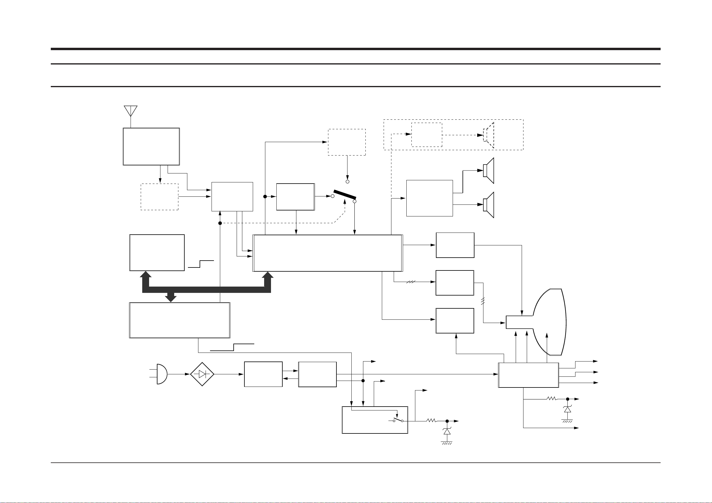
8. Block Diagram
8-1 S15A
Block Diagram
Samsung Electronics 8-1
TUNER
TECC0949VG28A(S)
TELE4-108A
TECC0949VG28B
TELE4-125A
Pre-AMP
PAP103T
S/W VIF SAW
K2971M/K7252M
PAL/NTSC
BPF
5.5/6.5MHz
PAL SIF
1CHIP
IF/VIDEO/CHROMA/DEFLECTION
TDA8842 / TDA8841
EEP-ROM
X24C04P
KS24C040
IC-MCU
POWER-CORD
DIODE-BRIDGE
D2SB60
STR
KA2S0680RF
SWITCHING
TRANS
NORMAL
STANDBY
TO SOUND IC B+ 12.5V
TO µ-COM B+ 5V
FBT
20" FSV-20A001
21"
14" FSV-14A001
SOUND AMP
1CH x 3W
TDA7056B
OPTION
SPEAKER
16R x 1EA
SOUND AMP
TDA7057AQ
4W x 2CH
TDA7056B
3WX2CH
VERTICAL AMP
TDA8356
RGB-AMP
TDA6107Q
H-OUT TR
KSC5386YD
CRT
FBT B+ 125V
SWITCH MULTI
REGULATOR
KA7630
TO 1CHIP B+ 8V
SPEAKER
8R x 2EA or 16R x 2EA
BPF
4.5MHz
NTSC SIF
NTSC
PAL
I2C BUS
MONO SPEAKER
DUAL SPEAKER
CD/CB/CK MODEL DELETE
Z90203
Z90234
SAA5291
TO TTX B+ 5V
U-COM
TO B+ 5V TUNER
PRE AMP
SAW SWITCHING
16.5V TO TDA8356
HDT B
180V TO CRT
46V TO TDA8356
HEAT TO CRT
+
CD/CB/CK MODEL
DELETE
Z90233
Page 41
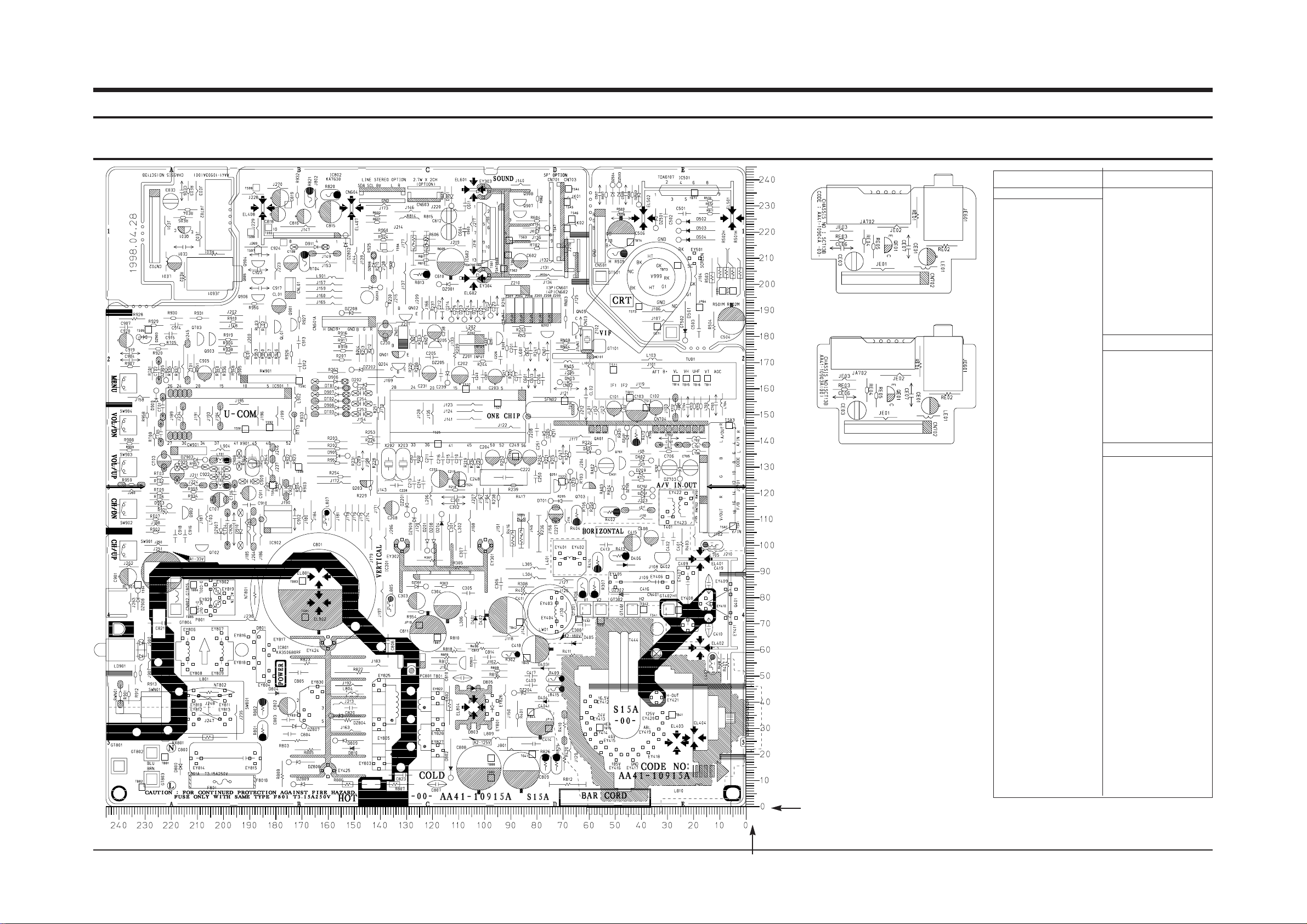
10. PCB Layout
10-1 PCB Main
PCB Layout
Samsung Electronics 10-1
D201 122 98
D202 149 161
D204 116 112
D205 77 139
D208 119 98
D209 43 127
D210 67 128
D211 102 186
D212 97 188
D213 107 186
D214 112 186
D401 103 78
D402 100 78
D403 84 53
D404 83 40
D405 72 62
D406 39 92
D501 23 178
D502 25 224
D503 25 220
D504 25 217
D701 74 117
D800 216 19
D801 188 65
D802 113 11
D803 104 38
D805 97 45
D809 157 25
D810 157 22
D901 112 230
D903 220 115
D905 152 134
D906 153 162
D907 153 157
D908 153 152
D909 225 159
D910 193 100
D911 161 214
DA01 56 135
DA02 36 132
DN03 71 162
DT01 153 160
DT02 153 155
DT03 153 150
DZ201 129 111
DZ202 151 167
DZ203 140 198
DZ204 88 43
DZ205 114 162
DZ208 154 189
DZ301 122 84
DZ302 54 81
DZ401 45 145
DZ501 34 221
DZ502 41 230
DZ503 48 238
DZ504 51 238
DZ701 35 118
DZ702 35 121
DZ703 25 125
DZ704 76 221
DZ705 46 118
DZ802 153 218
DZ803 107 57
DZ804 158 34
DZ806 142 211
DZ807 169 30
DZ808 175 17
DZ809 173 8
DZ901 117 200
DZ902 207 132
DZ903 232 179
DZ905 222 163
DZ907 201 100
DZ908 232 82
DZ909 127 113
HC101 59 172
IC201 86 141
IC301 99 100
IC501 39 225
IC602 100 235
IC801 160 13
IC802 151 229
IC901 175 142
IC902 183 114
Q201 95 176
Q202 78 182
Q203 147 124
Q204 135 169
Q205 116 175
Q251 73 120
Q401 17 94
Q402 34 95
Q701 48 129
Q703 57 121
Q901 174 182
Q902 215 110
Q903 205 176
Q904 189 209
Q905 189 202
Q906 189 196
Q907 89 228
Q908 89 232
QA01 52 136
QE01 217 222
QL01 180 181
QN01 135 174
QN02 132 188
QN05 66 180
QT02 210 100
QT03 210 176
Loc. No. X Y
DIODE
IC
Loc. No. X Y
TRANSISTOR
X
Y
Page 42
10. Wiring Diagram
10-1 S15A
Wiring Diagram
Samsung Electronics 10-1
1
2
3
4
5
6
7
8
SOUND L IN
SOUND L OUT
SOUND R OUT
FRONT VIDEO IN
GND
21 PIN VIDEO IN
GND
CRT PCB
POWER
CORD
1234
5
CUT/OFF
G-OUT
R-OUT
B-OUT
GND
1
2
3
4
R+ OUT
L- OUT
R- OUT
L+ OUT
CN501B
CN602
CN701
9
10
11
SOUND R IN
GND
FRONT AUDIO OUT
21 PIN AUDIO IN
67
8
HEAT
180V
GND
 Loading...