

Page 1

Alignment and Adjustments
Samsung Electronics 4-1
4. Alignment and Adjustments
4-1 Preadjustment
4-1-1 Factory Mode
1. Do not attempt these adjustments in the Video
Mode.
2. The Factory Mode adjustments are necessary
when either the EEPROM (IC902) or the CRT
is replaced.
3. Do not tamper with the “Adjustment” screen
of the Factory Mode menu. This screen is
intended only for factory use.
4-1-2 When EEPROM (IC902) Is Replaced
1. When IC902 is replaced all adjustment data
revert to initial values. It is necessary to
re-program this data.
2. After IC902 is replaced, warm up the TV for
10 seconds.
4-1-3 When CRT Is Replaced
1. Make the following adjustments AFTER setting up after setting up purity and convergence :
White Balance
Sub-Brightness
Vertical Center
Vertical Size
Horizontal Size
Fail Safe (This adjustment must be the last
step).
2. If the EEPROM or CRT is replaced, set PVAto
45 (factory mode) and set SC as follows.
14, 16 inch : 0
20 inch : 10
21 inch : 12
4-2 Factory/Service Mode
4-2-1 Procedure for the “Adjustment” Mode
1. This mode uses the standard remote control.
The Service Mode is activated by entering the
following remote-control sequence :
(1) SLEEP→FACTORY.
(2) STAND-BY→ DISPLAY→ P.STD→ MUTE
→POWER ON.
2. The “SERVICE (FACTORY)” message will be
displayed. The Service Mode has four components: Adjustment, Test Pattern, Option Bytes
and Reset.
3. Access the Adjustment Mode by pressing the
“VOLUME” keys ( Up or Down). The adjustment parameters are listed in the accompanying table, and selected by pressing the CHANNEL keys (▲ ,▼).
4. Selection sequences for the all system:
DOWN or UP key:
AGC>VCO>SBT>SCT>SCR>SC>RG>GG>
BG>CDL>BLU>PSL>PVS>PVA>PHS>NSR>
STT
5. The VOLUME keys increase or decrease the
adjustment values (stored in the
non-volatile memory) when Adjustment Mode
is cancelled.
6. Cancel the Adjustment Mode by re-pressing
the “FACTORY” or “Power OFF” keys.
Page 2
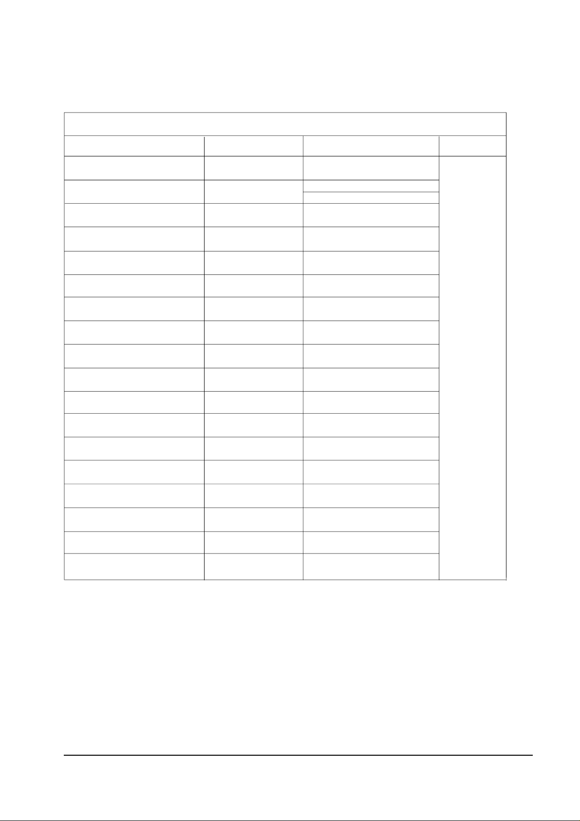
4-2-2 Main Adjustment Parameter
NOTE : PVS,PVA, PHS, parameters must be aligned using the 50Hz vertical-field rates.
Alignment and Adjustments
4-2 Samsung Electronics
INITIAL DATA
10
8
10
10
47
32
34
32
32
42
40
7
0
80
12
4
0
REMARK
TDA8842
TDA8841
RANGE
0 ~ 63 STEP
0 ~ 23 STEP
0 ~ 23 STEP
0 ~ 23 STEP
0 ~ 63 STEP
0 ~ 63 STEP
0 ~ 63 STEP
0 ~ 63 STEP
0 ~ 63 STEP
0 ~ 63 STEP
0 ~ 63 STEP
0 ~ 23 STEP
1 ~ 13 STEP
0 ~ 128 STEP
0 ~ 1 STEP 1 (For East Europe)
0 ~ 63 STEP
0 ~ 63 STEP 16 (Only TTX Model)
0 ~ 7 STEP
0 ~ 3 STEP
OSD ABBREVIATION
AGC
SBT
SCT
SCR
RG
GG
BG
PSL
PVS
PVA
PHS
NSR
STT
VCO
SC
TSS
CDL
BLU
FUNCTION
AUTO GAIN CONTROL
SUB BRIGHT
SUB CONTRAST
SUB COLOR
RED DRIVE GAIN
GREEN DRIVE GAIN
BLUE DRIVE GAIN
PAL VERTICAL SLOPE
PAL VERTICAL SHIFT
PAL VERTICAL AMPLITUDE
PAL HORIZONTAL SHIFT
NTSC SUB COLOR
SUB TINT
VOLTAGE CONTROL OSCILLATOR
S-CORRECTION
TTX SUB-CONTRAST
CATHODE DRIVE LEVEL
BLUE STRETCH MODE
µ
Table 4-1 Main Adjustment Parameter (Zilog, Phlips -com)
Page 3
Alignment and Adjustments
Samsung Electronics 4-3
4-2-3 Test Pattern (Aging Mode)
1. This mode can be used during servicing, or for confirming that the convergence and
purity adjustments are correct.
2. Access the Test Pattern parameters by pressing a CHANNEL keys (▲ ,▼) while the
Service Mode is on. The cursor will move to the test pattern. Press the VOLUME
keys. On-screen display:
•
WHITE
•
AGING
3. AGING Mode (Reference Only)
This pattern is used for pre-heating the CRT during manufacturing
—it is accessed in the factory by twice pressing the “SLEEP → FACTORY→FACTORY
“ key, then white pattern will be displayed.
Even if the TV power is cut off, the Aging Mode is not cancelled, The aging mode is
cancelled by repressing the “FACTORY” key or pressing the local “CH UP/DOWN”
keys.
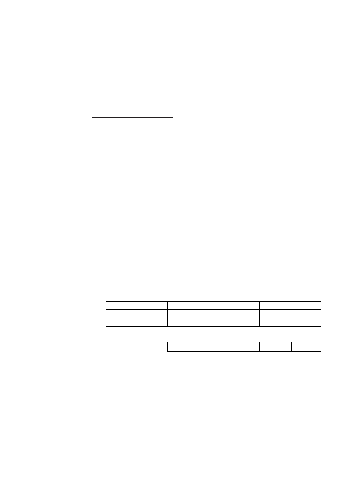
4-2-4 Option Bytes
In the Service Mode, various can be selected via the Option Bytes (8 bits each). Example:
NON -TTX MICOM ONLY
TTX MICOM
SYSTEM OSD DISPLAY
BYTE 0 : 8 BYTE 1 : 0 -
TDA8842, CK SYSTEM, RCA JACK SYSTEM OSD DISPLAY
BYTE 0 : 11
BIT 6
L (BIT :0)
BIT 5
L (BIT : 0)
BIT 4
L (BIT : 0)
L (BIT : 0)
L (BIT : 1) H (BIT : 0) L (BIT : 0) H (BIT : 0) L (BIT : 1)
BIT 3
H (BIT : 8)
L (BIT : 0)
BIT 2
L (BIT : 0)
L (BIT : 0)
BIT 1
L (BIT : 0)
L (BIT : 0)
BIT 0
L (BIT : 0)
L (BIT : 0)
Page 4
Alignment and Adjustments
4-4 Samsung Electronics
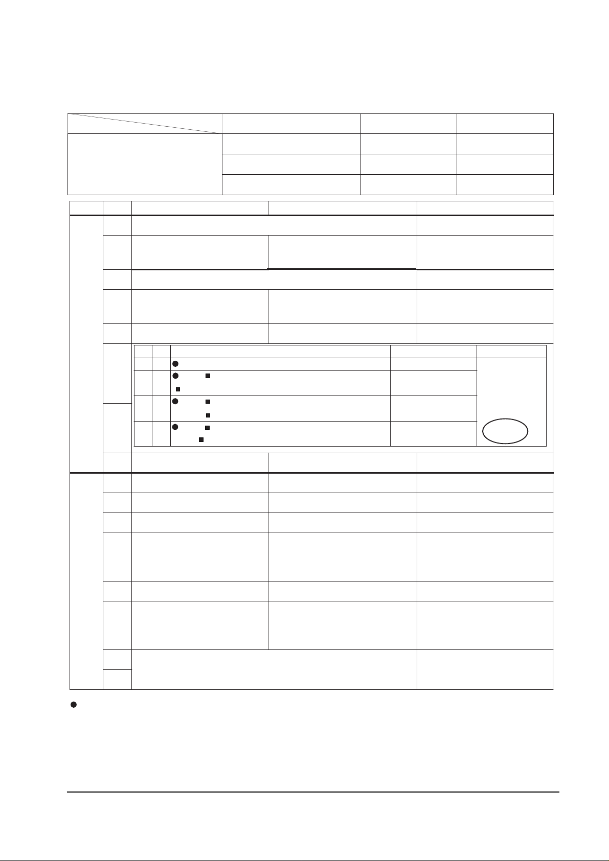
4-2-4 (A) NON-TTX MICOM (SZM-173EC) OPTION BYTE (FOR CHINA/SINGAPORE/GERMAN ARMY)
BYTE BIT LOW (0) HIGH (1) Application MICOM
B
Y
T
E
0
D7 NOT USED MUST LOW
D6
TV : NORMAL ZOOM
A/V :NORMAL ZOOM
TV: NORMAL ZOOM 16:9
A/V : NORMAL ZOOM
D5 NOT USED MUST = LOW
D4
CH Up/down functional in
the A/V Mode (SCART Jack)
CH Up/down not functional in
the A/V Mode (RCA Jack)
D3 Sound-I System Used Sound-I System Not Used
D2
D1
D0 TDA8374A TDA8842 IC201 (ONE-CHIP) OPTION
B
Y
T
E
1
D7 TV OUT MONITOR OUT
D6 English ONLY English/Chinese
D5 AFT ON (always) AFT OFF (after fine tuning) BASIC = LOW
D4
Existing Sharpness level
(when using the TDA6108
RGB AMP)
Sharpness level up
(when using the TDA6107Q
RGB AMP)
D3 No Auto Power On Auto Power On
D2
NTSC : 25KHz (NTSC TABLE
)
PAL : 50KHz (PAL TABLE)
NTSC : 25KHz (NTSC TABLE)
PAL : 27KHz (NTSC TABLE)
D1
NOT USED (D1 D0 = MUST 00)
D0
D2 D1
COLOR SYSTE M SOUND SYSTEM Re mark
0 0
CK : AUTO ( NO OSD ) B/G D/K
German Army : CS
0 1
CW : RF : AUTO PAL SECAM NT4.43
A/V : AUTO PAL SECAM NT4.43 NT3.58
B/G D/K I
1 0
CD : RF : AUTO PAL NT4.43
A/V : AUTO PAL NT4.43 NT3.58
D/K I
1 1
CS : RF:AUTO PAL SECAM NT4.43 NT3.58
A/V: AUTO PAL SECAM NT4.43 NT3.58
B/G D/K (I)
NT- M
D3 BIT
OPTION
Function Required : 1. PICTURE OFF (after 15 minutes) during no signal
2. AUDIO MUTE during no signal
3. BLUE SCREEN ON/OFF
4. TIMER CLOCK ON/OFF
5. No CHILD LOCK
Destination BYTE 0 BYTE 1
MP (Massproduction)
OPTION BYTE
China 15 D8
Singapore 57 58
German Army 57 18
→
→
→
→
→
→
→
→
→
→
→
→
→
→
→
→→
→
→
→
→
→
→
→
→
→→
→
→
→
↔
→
→
→
→
→
MUST = LOW : China (only)
16 : 9 (Delete)
MUST = HIGH
China MP : CD
"?"
"?"
"?"
"?"
HIGH (For China)
MUST = HIGH
BASIC = HIGH
BASIC = HIGH
→
Page 5
Alignment and Adjustments
Samsung Electronics 4-5
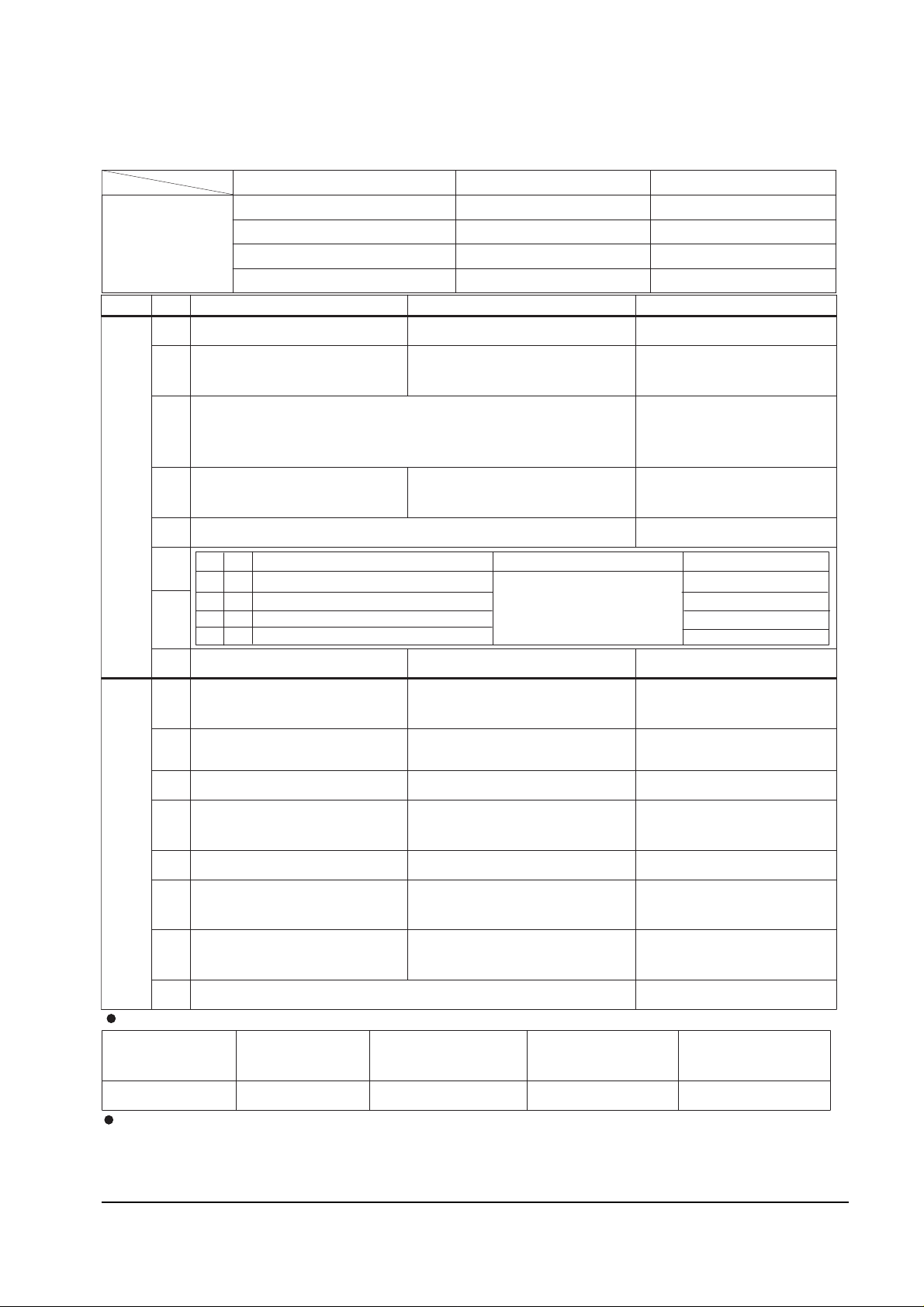
4-2-4 (B) NON-TTX MICOM (SZM-173EW/EE) OPTION BYTE (FOR EUROPE)
BYTE BIT LOW(0) HIGH(1) Remark
B
Y
T
E
0
D7
3BAND UHF ONLY
HIGH (UK only)
D6
TV : NORMAL ZOOM
A/ : NORMAL ZOOM
TV : NORMAL
ZOOM 16:9
A/V : NORMAL ZOOM
MUST = HIGH
D5 MUST LOW
POL AN D OPTIO N
- R913 : 680 added
- J901 :
D4
CH Up/down functional in the
A/V Mode (SCART Jack)
CH Up/down not functional in
the A/V Mode (RCA Jack)
MUST = LOW
D3
NOT USED MUST = LOW
D
2
D
1
D0 TDA8374A TDA8842 IC201 (ONE-CHIP) OPTION
B
Y
T
E
1
D7
English/German/Dutch/Italian/Spnish/
Swedish/Croatian/Yugo/Greek
Western Europe
(SZM-173EW)
D6
English/Romanian/Hungarian/Polish/
Czech
/B ulgarian
Eastern Europe (SZM-173EE)
D5 AFT ON (always) AFT OFF (after fine tuning) MUST = LOW
D4
Existing sharpness level :
TDA6108
Sharpness level up : TDA6107Q MUST = HIGH
D3 No Auto Power On Auto Power On
D2
NTSC : 25 KHz (NTSC TABLE)
PAL : 50 KHz (PAL TABLE)
NTSC : 25KHz(NTSC TABLE)
PAL : 27KHz(NTSC TABLE)
- F rance/ Swiss : HIGH
- Others : L OW
D1 PAL / SECAM SECAM - L
- France/Swiss (only) : HIGH
- SZM-173EW (only)
D0 MUST : LOW
D2 D1
SOUND SYSTEM COLOR SYSTEM Destination
0 0 (?)
B/G D/K : CK MODEL
AUTO : NO OSD
Eastern Europe/France/Swiss
0 1 I ONLY ( NO OSD ) : CI,CII MDL United Kingdom
1 0 B/G ONLY (NO OSD ) : CB,CX MDL Western Europe
1 1 NOT USED
Destination BYTE 0 BYTE 1
MP OPTION
BYTE
United Kingdom C3 98
France/Swiss 41 9E
Western Europe (except UK) 45 98
Eastern Europe 41 58
P-STD Classification ( CON./BRI./SHAR ./COL )
STANDARD
MODE
DYNAMIC
MODE
MOVIE MODE MILD MODE CUSTOM MODE
90/50/50/50 100/50/75/50 90/50/75/50 60/50/50/50 90/50/50/50
Function Required: 1. PICTURE OFF (after 15 minutes) during no signal. 2. AUDIO MUTE during no
3. No BLUE SCREEN during no RF signal (Blue Screen during AV).
4. No TIMER. 5. No CHILD LOCK. 6. See "Detailed functions of CF".
→
→
→
→
→
Ω
→↔
signal.
MUST = HIGH
Page 6

Alignment and Adjustments
4-6 Samsung Electronics
4-2-4 C) NON-TTX MICOM (SZM-173ER) OPTION BYTE (FOR RUSSIA)
Destination BYTE 0 BYTE 1
Russia,CIS 49 58
Australia 5D 18
BYTE BIT LOW(0) HIGH(1) Remark
B
Y
T
E
0
D7
D6
TV : NORMAL
ZOOM
A/V : NORMAL ZOOM
TV : NORMAL ZOOM 16:9
A/V : NORMAL ZOOM
D5
D4
CH Up/down functional in the
A/V Mode (SCART Jack)
CH Up/down not functional in
the A/V Model (RCA Jack)
D3 PAL-I Used PAL-I Not Used
D
2
D
1
D0 TDA8374A TDA8842 IC201 (ONE-CHIP) OPTION
B
Y
T
E
1
D7
D6 English English/Russian
D5 AFT ON (always) AFT OFF (after fine tuning)
D4
Existing sharpness level
(when using the TDA6108 RG AMP)
Sharpness level up
(when using the TDA6107Q AMP)
D3 No Auto Power On Auto Power On
D2
NTSC: 25 KHz (NTSC TABLE)
PAL : 50 KHz (PAL TABLE)
NTSC : 25 KHz (NTSC TABLE)
PAL : 27 KHz (NTSC TABLE)
D1
D0
Function Required : 1. PICTURE OFF (after 15 minutes) during no signal
2. AUDIO MUTE during no signal
SCREEN available
4. TIMER available
5.
P-STD Classification ( CON/BRI/SHAR/COL )
STANDARD
MODE
DYNAMIC
MODE
MOVIE MODE MILD MODE CUSTOM MODE
90/50/50/50 100/50/75/50 90/50/75/50 60/50/50/50 90/50/50/50
D2 D1 SOUND SYSTEM COLOR SYSTEM
0 0 (?)
B/G D/K : CK MODEL
AUTO : NO OSD
0 1 I ONLY (NO OSD ) : CI,CII MD L
1 0 B/G ONLY (NO OSD ) : CB,CX MDL
1 1 NOT USED
→
→
→
→
→
→↔
3. BLUE
MUST = LOW
MUST = HIGH
MUST = LOW
MUST = HIGH
MUST = LOW
MUST = LOW
MUST = HIGH
BASIC = HIGH
NOT USED (MUST = LOW)
No CHILD LOCK
Page 7

Alignment and Adjustments
Samsung Electronics 4-7
4-2-4 (D) NON-TTX MICOM (SZM-173AR/EA) OPTION BYTE (FOR MIDDLE RAST/AFRICA)
BYTE BIT LOW (0) HIGH (1) Remark
B
Y
T
E
0
D7
D6
TV : NORMAL ZOOM
A/V : NORMAL ZOOM
TV : NORMAL ZOOM 16:9
A/V : NORMAL ZOOM
D5 NOT USED CHILD LOCK ON
D4
CH Up/down functional in the
A/V Mode (SCART Jack)
CH Up/down not functional in the
A/V Model (RCA Jack)
Middle East : HIGH
Africa : LOW
D3 Sound-I System Used Sound-I System Not Used
Middle East : HIGH
Africa : LOW
D
2
D
1
D0 TDA8374A TDA8842 IC201 (ONE-CHIP) OPTION
B
Y
T
E
1
D7
D6
D5 AF T ON (always) AFT OFF after fine tuning
D4
Existing sharpness level (when
using the TDA6108 RGB AMP)
Sharpness level up (when using the
TDA6107Q RGB AMP)
D3 No Auto Power On Auto Power On
D2
NTSC : 25 KHz ( NTSC TAB LE)
PAL : 50 KHz ( PAL T AB LE)
NTSC : 25 KHz (NTSC TABLE)
PAL : 27 KHz (NTSC TABLE)
D1
MUST : DO D1 = 00
D0
D2 D1 COLOR SYSTEM SOUND SYSTEM
0 0
CK : AUTO (NO OSD ) "?" B/G D/K
0 1
CW : -. RF : AUTO PAL SECAM NT4.43
-. A/V : AUTO PAL SECAM NT4.43 NT3.58
"?" B/G D/K I
1 0
CB : - RF : PAL ONLY
- A/V : AUTO PAL NT4.43 NT3.58
B/G ONLY (NO OSD)
1 1
CS : -. RF : AUTO PAL SECAM NT4.43 NT3.58
-. A/V : AUTO PAL SECAM NT4.43 NT3.58
"?" B/G D/K I
NT-
M
Destination BYTE 0 BYTE 1
MP OPTION
BYTE
Middle East (EA or AR) 7F 58
Africa (EA) 67 D8
D7 D6 LANGUAGE Remark
0 0 - NOT USED
0 1 ENG / ARAB Middle East
1 0 - NOT USED
1 1 ENG / ARAB / FRENCH EA VERSION (Africa ONLY)
Function Required : 1. PICTURE OFF (after 15 minutes) during no signal
2. AUDIO MUTE during no signal.
SCREEN ON/OFF
4. TIMER (CLOCK ON/OFF)
5. C HILD L OC K ON (always)
→
→→
→
→
→→
→→
→
→
→
→
→
→
→
→
→
→
→
→
→
→
→
→
→
→
→
→
→
→→→
3. BLUE
MUST = LOW
MUST = HIGH
MUST = HIGH
MUST = HIGH
MUST = LOW
MUST = HIGH
Page 8

Alignment and Adjustments
4-8 Samsung Electronics
4-2-4 (E) NON-TTX MICOM (SZM-173EV/ET) OPTION BYTE (FOR ASIA)
BYTE BIT LOW (0) HIGH (1) Remark
B
Y
T
E
0
D7 LINE STEREO OFF LINE STEREO ON SZM-173EV (only)
D6
TV : NORMAL ZOOM
A/V : NORMAL ZOOM
TV : NORMAL ZOOM 16:9
A/V : NORMAL ZOOM
D5 MUST = LOW
D4
CH Up/down functional in the
A/V Mode (SCART Jack)
CH Up/down not functional in
the A/V Mode (RCA Jack)
D3 Sound-I System Used Sound-I System Not Used
D2
D1
D0 TDA8374A TDA8842 IC201 (ONE-CHIP) OPTION
B
Y
T
E
1
D7 TV OUT MONITOR OUT
D6 English ONL Y
English/Vietnamese/Indonesian/Malay SZM-173EV
English/Thai SZM-173ET
D5 AFT ON (always) AFT OFF (after fine tuning)
D4
D3 No Auto Power On Auto Power On
D2
NTSC : 25 KHz (NTSC TA B LE)
PAL : 50 KHz (P AL TABLE)
NTSC : 25 KHz (NTSC TABLE)
PAL : 27 KHz (NTSC TABLE)
D1
D0 MUST = LOW
D2 D1
COLOR SYSTEM SOUND SYSTEM Destination
0 0
CK :AUTO (NO OSD)
"?" B/G D/K
0 1
CW : -. RF : AUTO PAL SECAM NT4.43
-. A/V : AUTO PAL SECAM NT4.43 NT3.58
"?" B/G D/K I
1 0
CB : - RF : PAL ONLY
- A/V : AUTO PAL NT4.43 NT3.58
B/G ONLY (NO OSD)
Indonesia/Thailand/
India
1 1
CS: - RF : AUTO PAL SECAM NT4.43 NT3.58
-A/V : AUTO PAL SECAM NT4.43 NT3.58
"?" B/G D/K
I
NT- M
Vietnam
Malaysia
Destination BYTE 0 BYTE 1
OPTION BYTE
Vietnam/Malaysia (NO LINE STEREO) 5F 58
Vietnam (LINE STEREO MODEL) DF D8
Thailand 5D 58
Indonesia 5D 5A
India 5D 18
SZM -173ET (16K) : Z90203 WITHOUT LINE STEREO
SZM -173EV (24K) : Z90234 WITH LINE STEREO
Function Required : 1. PICTURE OFF (after 15 minutes) during nosignal. 2. AUDIO MUTE during no
signal.
BLUE SCREEN ON/OFF. 4. TIMER (CLOCK ON/OFF).
5. No CHILD LOCK
→
→
→
→
→
→
→
→
→
→
→
→
→
→
→
→
→
→
→
→
→
→
→
→
→
→→→
→
→
→
→
3.
→
→
Existing sharpness level
(when using the TDA6108 RGB AMP)
Sharpness level up (when using the
TDA6107Q RGB AMP)
MUST = HIGH
CLOCK DISPLAY OFF
CLOCK DISPLAY ON Indonesia ONLY : HIGH
MUST = HIGH
BASIC = HIGH
MUST = HIGH
BASIC = HIGH
MUST = LOW
Page 9

Alignment and Adjustments
Samsung Electronics 4-9
4-2-4 (F) TTX MICOM (SZM-175EA/EP) OPTION BYTE (FOR MIDDLE EAST ASIA)
BYTE BIT LOW (0) HIGH (1) Application MICOM
B
Y
T
E
0
D7 NOT USED ALL = LOW
D6
TV : NORMAL ZOOM 16:9
A/V : NORMAL ZOOM
TV : NORMAL ZOOM 16:9
A/V : NORMAL ZOOM 16:9
MUST = LOW
D5 NOT USED ALL = LOW
D4
CH Up/down functional in
the A/V Mode (SCART Jack)
CH Up/down not functional in
the A/V Mode (RCA Jack)
Africa : SCART
Others : RCA
D3 Sound-I System Used Sound-I System Not Used SOUND-I : Africa(only)
D2
D1
D0 TDA8374A T DA 8842
B
Y
T
E
1
D7
NOT USED ALL = LOWD6
D5
D4
Existing sharpness level
(when using the TDA6108
RGB AMP)
Sharpness level up
(when using the TDA6107Q RGB
AMP)
ALL (BASIC = HIGH)
TEST Unnecessary
D3 No Auto Power On Auto Power On ALL (BASIC = HIGH)
D2
NTSC : 25 KHz (NTSC TABLE)
PAL : 50 KHz (PAL TABLE)
NTSC : 25 KHz (NTSC TABLE)
PAL : 27 KHz (NTSC TABLE)
D1
D1 D0 = MUST 00 MUST = LOW
D0
D2 D1
COLOR SYSTEM SO U N D
SY STE M Remar k
0 0 CK : AUTO (NO OSD) B/G D /K
No sound
systemin the A
/V
M O D E
0 1
CW : RF : AUTO PAL SECAM NT4.43
A/V : AUTO PAL SECAM NT4.43 NT3.58
B/G D /K I
1 0
CB : RF : PAL ONLY (NO OSD)
A/V : AUTO PAL NT4.43 NT3.58
B/G O NL Y (NO O SD)
1 1
CS : RF : AUTO PAL SECAM NT4.43 NT3.58
A/V : AUTO PAL SECAM NT4.43 NT3.58
B/G D /K
I
NT M
Function Required : 1. PICTURE OFF (after 15 minutes) during no signal
2. AUDIO MUTE (during no signal)
3. No BLUE
SCREEN
4. No TIMER
5. No CHILD LOCK
OSD language by micom
1. Persian (for Iran) : SPM-175EP : English/Persian (Iranian)
2. Arab (Middle East, Africa) : SPM-175EA : English/French/Arabian
MP
OPTION
BYTE
Destination Application MICOM BYTE0 BYTE1
Iran (Persian TTX) SPM-175EP 1F 18
Middle East (except Iran)
SPM-175EA
1F 18
Africa 07 18
→
→
→
→
→
→
→
→→
→
→→ → →
→
→→
→
→
→
→
→
→
→→
→→
→→
→→→→
→
→
−
−
"?"
"?"
→
"?"
Page 10

Alignment and Adjustments
4-10 Samsung Electronics
4-2-4 (G) TTX MICOM (SPM-175EE/ER/EG) OPTION BYTE (FOR EUROPE)
BYTE BIT LOW(0) HIGH(1) Remark
B
Y
T
E
0
D7 3 BAND UHF DNLY (UK only)
D6
TV : NORMAL ZOOM 16:9
A/V : NORMAL ZOOM
TV : NORMAL ZOOM 16:9
A/V : NORMAL ZOOM 16:9
D5
<POL AND OP TIO N>
R913 : 680 added. J901 : Delete
D4
CH Up/Down functional in the
A/V Mode (SCART Jack)
CH Up/Down not functional in
the A/V Model (RCA Jack)
MUST = LOW
D3 P-STD NORMAL P-STD MAX MUST = LOW
D2
D1
D0 TDA8374A TDA8842
B
Y
T
E
1
D7 NOT USED
D6 PAL/SECAM SECAM - L HIGH (CF only)
D5
English/German/French/Dutch/
Italian/Spanish/Swedish
English/Croatian/Romanian/
Hungarian/Polish/Czech
This bit is only appied to
SPM-175EE
D4
Existing sharpness level
(when using the TDA6108
RGB AMP)
Sharpness level up
(when using the TDA6107Q AMP)
TEST Unnecessary
D3 No Auto Power On Auto Power On
D2
NTSC : 25K Hz (NTSC TAB LE)
PAL : 50K Hz (PAL TAB LE)
NTSC : 25K Hz (NTSC TAB LE)
PAL : 27K Hz (NT SC TAB LE)
AL L (R F V O L . C UR V E
)
BASIC :LOW
D1 MUST = LOW
D0 MUST = LOW
D2 D1
SOUND SYSTEM COLOR SYSTEM Remark
0 0 (?)
B/G D/K : CK MODEL
AUTO
(NO OSD)
No SOUND SYSTEM
in the A/V Mode
0 1 I ONLY (NO OSD) : CI,CII MODEL
1 0 B/G ONLY (NO OSD): CB,CX MODEL
1 1 NOT USED
Destination Application MICOM BYTE 0 BYTE 1 LANGUAGE
MP
OPTION
BYTE
United Kingdom
SPM-175EE
83 18
See BYTE 1 D5
Other Western Europe 05 18
Eastern Europe 01 38
France/Swiss SPM-175E 01 5C
Yugo/Greece SPM-175EG 05 18 English/Yugo/Greek
Russia/Bulgaria SPM-175ER 01 18 English/Russian/Bulgarian
P-STD Classification (CON/BRI/SHRP/COL)
D3 BIT STANDARD MODE DYNAMIC MODE MOVIE MODE MILD MODE CUSTOM MODE
0 90/50/50/50 100/50/50/50 75/55/50/50 60/50/50/50 90/55/25/50
Function Required :1. PICTURE OFF (after 15 minutes) during no signal. 2. AUDIO MUTE (during no
3. No BLUE SCREEN. 4. No TIMER (CLOCK /OFF). 5. No CHILD LOCK
→
→
→
→
→
→
→
W
→↔
→
signal).
MUST = LOW
ALL = LOW
ALL BASIC = HIGH
ALL BASIC = HIGH
Page 11

4-3 Other Adjustments
4-3-1 General
1. Usually, a color TV needs only slight touchup adjustment upon installation. Check the
basic characteristics such as height, horizontal
and vertical sync and focus.
2. The picture should have good black and white
details. There should be no objectionable
color shading; if color shading is present, perform the purity and convergence adjustments
described below.
3. Use the specified test equipment or its equivalent.
4. Correct impedance matching is essential.
5. Avoid overload. Excessive signal from a sweep
generator might overload the front-end of the
TV. When inserting signal markers, do not
allow the marker generator to distort test
results.
6. Connect the TV only to an AC power source
with voltage and frequency as specified on the
backcover nameplate.
7. Do not attempt to connect or disconnect any
wires while the TV is turned on. Make sure
that the power cord is disconnected before
replacing any parts.
8. To protect against shock hazard, use an isolation transformer.
4-3-2 Automatic Degaussing
A degaussing coil is mounted around the picture tube, so that external degaussing after
moving the TV should be unnecessary. But
the receiver must be properly degaussed upon
installation.
The degaussing coil operates for about 1 second after the power is switched ON. If the set
has been moved or turned in a different direction, disconnect its AC power for at least 30
minutes.
If the chassis or parts of the cabinet become
magnetized, poor color purity will result. If
this happens, use an external degaussing coil.
Slowly move the degaussing coil around the
faceplate of the picture tube and the sides and
front of the receiver. Slowly withdraw the coil
to a distance of about 6 feet before removing
power.
4-2-5 RESET
The Reset Mode is used during factory inspection.
Function Reset:
1. Channels Add/Erase
2. Sort Non
3. System Auto
4. Timer off
5. Blue Screen off
6. Child Lock off
7. Picture standard
8. Volume 10
9. CH. Skip Erased
Alignment and Adjustments
Samsung Electronics 4-11
Page 12

4-3-3 High Voltage Check
CAUTION: There is no high voltage adjustment on this chassis.
The B+ power supply must be set to +125 volts (Full color bar input
and normal picture level).
1. Connect a digital voltmeter to the second
anode of the picture tube.
2. Turn on the TV. Set the Brightness and
Contrast controls to minimum (zero beam current).
3. The high voltage should not exceed 27.5KV.
4. Adjust the Brightness and contrast controls to
both extremes. Ensure that the high voltage
does not exceed 27.5KV under any conditions.
4-3-4 FOCUS Adjustment
1. Input a black and white signal.
2. Adjust the tuning control for the clearest pic-
ture.
3. Adjust the FOCUS control for well defined
scanning lines in the center area of the screen.
4-3-5 Cathode Voltage Adjustment
(Screen Adjustment)
1. Connect CRT socket pin GK to an oscilloscope
probe.
2. Input a gray scale pattern. (Use a pattern gen-
erator, PM5518)
3. Use the P mode key (on the remote control)
for the STANDARD picture.
4. Adjust the Screen VR (on the FBT) so that the
voltage on the oscilloscope becomes 130+2.5V
(See Fig. 4-1).
4-3-6 Purity Adjustment
1. Warm up the receiver for at least 20 minutes.
2. Plug in the CRT deflection yoke and tighten
the clamp screw.
3. Plug the convergence yoke into the CRT and
set in as shown in Fig. 4-2.
4. Input a black and white signal.
5. Fully demagnetize the receiver by applying an
external degaussing coil.
6. Turn the CONTRAST and BRIGHTNESS controls to maximum.
7. Loosen the clamp screw holding the yoke.
Slide the yoke backward or forward to provide vertical green belt. (Fig. 4-3).
8. Tighten the convergence yoke.
9. Slowly move the deflection yoke forward,
and adjust for the best overall green screen.
10. Temporarily tighten the deflection yoke.
11. Produce blue and red rasters by adjusting the
low-light controls. Check for good purity in
each field.
12. Tighten the deflection yoke.
Alignment and Adjustments
4-12 Samsung Electronics
Fig. 4-1
130 2.5V
+
_
GND
14, 16" :120 2.5V
20, 21" : 130 2.5V
+
_
+
_
_
Page 13

4-3-7 White Balance Adjustment
Alignment and Adjustments
Samsung Electronics 4-13
Fig. 4-2 Convergence Magnet Assembly
4 Pole Magnet
6 Pole Magnet
2 Pole Magnet
Clamper
Screw
2 POLE
PURITY
YOKE
CLAMP
SCREW
6 POLE
CONVERGENCE
4 POLE
CONVERGENCE
ADJUST THE ANGL
(VERTICAL LINES)
Fig. 4-3 Center Convergence Adjustment
31m/m
Vertical Green Belt
Fig. 4-4
1
2
(a) Set up
1. Warm up the TV for at least 30 minutes in the
Aging Mode (OSD White). This mode is displayed by entering the following sequence:
SLEEP →FACTORY → FACTORY
2. Input a Toshiba pattern.
(b) Low-Light Adjustment
1. Set SBT to 1.3 ± 0.2 fL in the Factory Service
Mode with using CA100. See Fig. 4-4 ➁.
2. Adjust RG,BG so that the levels are suitable to
each local area.
(c) High-Light Adjustment
1. Set SCT to 55 FL (20”. 21”), 65 FL(14”.16”) in
the Factory Service Mode with using CA100.
See Fig. 4-4 ①.
Page 14

4-3-8 Center Convergence Adjustment
1. Warm up the receiver for at least 20 minutes.
2. Adjust the two tabs of the 4 pole magnets to
change the angle between them. Superimpose
the red and blue vertical lines in the center
area of the screen.
3. Adjust the Brightness and Contrast controls
for a well defined picture.
4. Adjust the two-tab pairs of the 4 pole magnets, and change the angle between them.
Superimpose the red and the blue vertical
lines in the center area of the screen.
5. Turn the both tabs at the same time, keeping
the angle constant, and superimpose the red
and blue horizontal line in the center of the
screen.
6. Adjust the two-tab pairs of the 6-pole magnets
to superimpose the red and blue line onto the
green. (Changing the angle affects the vertical
lines, and rotating both magnets affects the
horizontal lines.)
7. Repeat adjustments 2~6, if necessary.
8. Since the 4-pole magnets and 6-pole magnets
interact, the dot movement is complex
(Fig. 4-5).
Alignment and Adjustments
4-14 Samsung Electronics
4-3-9 VCO Adjustment
Fig. 4-5 Center Convergence Adjustment
RED
BLUE
BLUE
RED
4-Pole Magnet Movement
GREEN
RED/BLUE
RED/BLUE
GREEN
6-Pole Magnet Movement
Set the vco data to 80 (Factory Mode).
NOTE : For SZM-173EW and SPM-175E (Western Europe remote control), set the VCO data to 1.
Page 15

4-3-10 RF AGC Adjustment
Set the AGC data to 14 (Factory Mode).
4-3-11 Sub-Color Adjustment
Set SCR data to 10 (Factory Mode).
4-3-12 Geometry Adjustment
SC →PVA→PVS→ PSL →PHS
1. Input a lion head pattern (in the PAL channel).
2. Set the SC (S-Correction) as follows : 12 (21”),
10 (20”), 0 (14”,16”) and PVA 40 so that the
lion head circle becomes oval.
3. Adjust with PVS (Vertical shift) so that the top
margin of the picture is 4.
Fig. 4-7
4. Adjust with PSL (Vertical-Slope) so that the
bottom margin of the picture is 4.
Fig. 4-8
5. Adjust with PHS (Horizontal Shift) so that the
lion-head pattern and CRT centers are aligned.
Fig. 4-9
6. Adjust PHS (using the width coil) so that the
left and right margins of the picture are 5.
Alignment and Adjustments
Samsung Electronics 4-15
4
5
5
4
Page 16

MEMO
4-16 Samsung Electronics
 Loading...