

Samsung CGP1607 Disassemble
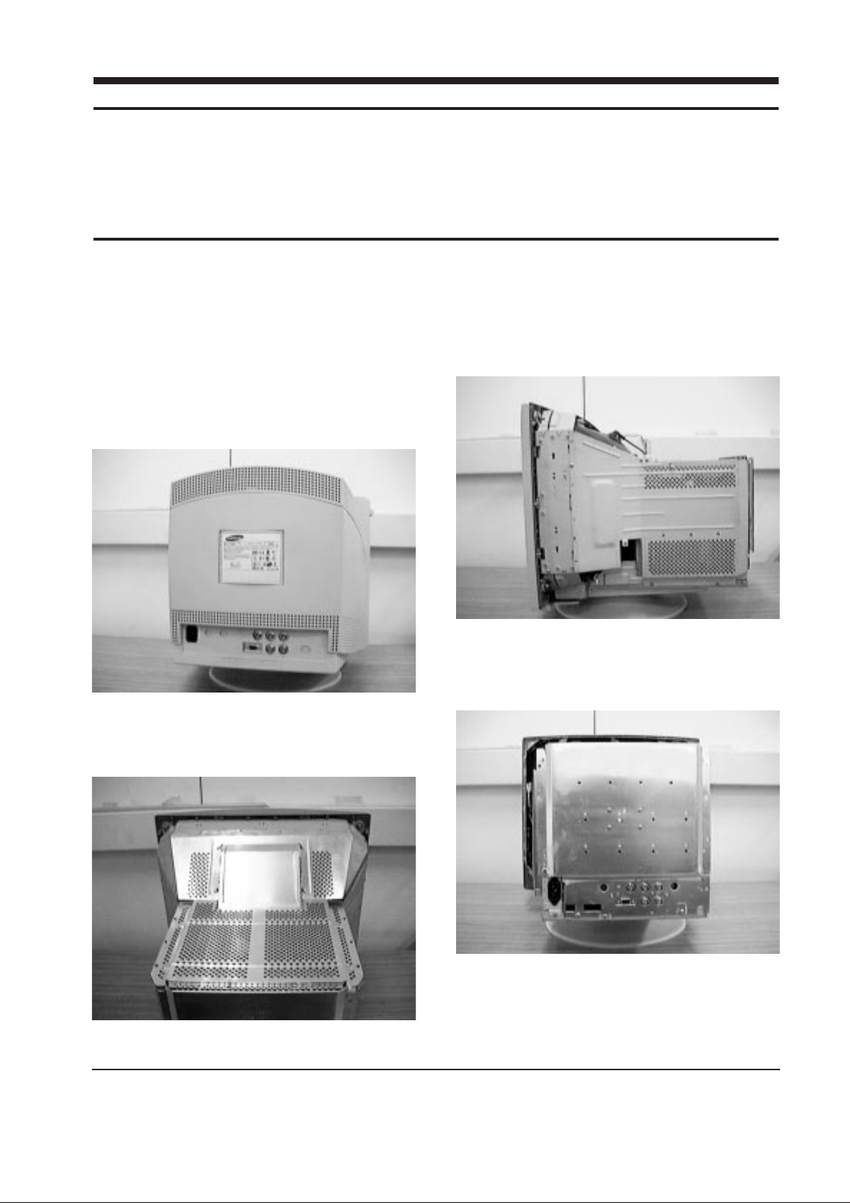
5-1-1 Disassembling the Cabinet
1. To uncover the 2 uppermost screws, press in
the end of each Screw Cap and pull it away
from the cabinet.
2. Remove the 4 screws on the Rear Cover and
pull it backward to remove it.
3. Remove the 6 screws on the Top Shield Cover
and remove it.
4. Remove the 6 screws and Chassis ground wire
on the side of both the Left and Right Shield
and remove the Shields.
5. Remove both side screws on the lower edge of
the Stand Assembly and pull the assembly
towards you to remove it.
SyncMaster 1000s (CGP1607L) 5-1
5 Disassembly and Reassembly
This section of the service manual describes the disassembly and reassembly procedures for the
SyncMaster 1000s (CGP1607L) monitor.
WARNING: This monitor contains electrostatically sensitive devices. Use caution when handling
these components.
5-1 Disassembly
Cautions:1. Disconnect the monitor from the power source before disassembly.
2. Follow these directions carefully; never use metal instruments to pry apart the cabinet.
Figure 5-1
Figure 5-3
Figure 5-2
Figure 5-4

5-1-2 Removing the Entire PCB Assembly
1. Complete all previous steps.
2. Using pinch-nosed pliers or long-nosed pliers,
carefully disconnect the Anode Cap from the
CRT.
3. Disconnect connector GTP901 on the CRT
Socket PCB.
4. Disconnect the CRT Socket PCB Assembly.
5. Disconnect connectors CN401_1~CN401_4,
C301_1~CN301_3, CN403, CN404 and CN405
on the Main PCB and CN605, CN606 on the
Power PCB.
6. Remove the 3 screws on the Main PCB Chassis
Bracket.
7. Lift off the entire PCB Assembly and place it
on a flat, level surface that is protected from
Static electricity.
5-1-3 Removing the CRT Socket PCB
1. Complete all previous steps.
2. Disconnect connectors CN104B, CN104RG and
G2 (GTP902) on the CRT Socket PCB.
3. Hold the CRT Socket PCB Assembly while
you lift the Cap on the CRT Socket and
desolder the two focus wires.
5-1-4 Removing the Video PCB
1. Complete all previous steps.
2. Disconnect connector CN801 on the Video
PCB.
3. Remove both side screws on the Video PCB
Assembly Rear Shield.
4. Lift off the Video PCB Assembly.
5. Remove all screws on the Video PCB
Assembly and remove the Video Shield.
6. Remove the 3 screws on the Video PCB.
7. Lift out the Video PCB and place it on a flat,
level surface that is protected from static
electricity.
5 Disassembly and Reassembly
5-2 SyncMaster 1000s (CGP1607L)
Figure 5-5
Figure 5-6
Figure 5-7
Figure 5-8
 Loading...