

Samsung CFT2790, CFT2791 Owner's Instructions Manual
Warning! Important Safety
Instructions
CAUTION
CAUTION: TO Rt DUCt TilE RISKOF [ LECTRIC SIIOCK, l)O NOT
REMOV[ COV[R (OR BACK) NO US[R SERVICD\BLll PARTS INSII)E
REFIR St RVK;ING TO QUALIFIIII) SERVICE P[ RSONNEL
This symbol indicates high voltage is plesenl
inskle It is dangerous to make any Mnd of
contact with any inside part of this pl_ducL
This symbol alerts you thai important literature
coi_(:eri_ii_g opera{ion and maintel_ai_ce has been
included with this product¸
Note to CATV szstem installer: This reminder is provided to call CATV system
installer_ attention to Article 820-40 of the National Electrical Code (Section 54 of
Canadian Electrical Code, Part I), that provides guidelines for proper grounding and,
in particular, specifies that the cable ground shall be connected to the grounding
system of the building as (lose to the point of cable entry as pra(ti(al.
Caution: FCC/CSA regulations state that any unauthorized changes or modifications to
this equipment may void the userls authority to operate it.
Caution: To prevent electric shock, match the wide blade of plug to the wide slot, and
f_dly insert the plug.
Attention: pour eviter les chocs electriques, introduire la lame le plus large de la fiche
dans la borne correspondante de la prise et pousser jusqn'au fond.
hnportant: One Federal Court has held that unauthorized recording of copyrighted TV
programs is an infringement of U.S. copyright laws.
Certain Canadian programs may also be copyrighted and any unauthorized recording
in whole or in part may be in violation of these rights.
Toprevent damage which may result infire or electric shock hazard,do not expose this
appliance to rain or moisture.
Important Safety Information
To redlme the risk of fire, electrical shock, and other it_jlMes, keep these safety precalltions in
mind when installing, using, and maintaining yollr machine.Read all safety and operating
insmlctions befbre operating the TV receiver.
• Retain the safety and operating instructions for future reference.
• Heed all warnings on the TV receiver and in the operating instructions.
• Follow all operating instructions.
• Unphlg the TV receiver from the wall outlet before cleaning, Use a damp cloth, Do riot use liquid or
aerosol cleaners.
• Never add any attacl-lments and/or equipmerlt without approval of the manufacturer. Such additiorls
may cause risk of fire, electric shock, or other personal ii_ur?:
• Do not use the TV receiver where corltact with or immersion irl water is a possibilit)a such as rlear bath
tubs, sinks, washing machirles, swimming pools, etc.
• Do not place the TV receiver on an unstable cart, stand, tripod, bracket, or table. The TV receiver may
fhll, causing inju U to people and/or damage to the T\( Use only with a cart, stand, tripod, bracket, or
table not recommended by the manufacturer or sold with the TV receiver.
• Follow the marlufhcturer_ irlstructions when mourlting the Ill-lit,and use a i'i]otlnting accessory recom-
mended by the manufacturer. Move the TV receiver and its cart with care. Quick stops,excessiveforce,
and lJrleverl slJrfaces Inay cause the IJnit and cart to overturn.
• Provide ventilation for the TV receiver. The unit is designed with slots in the cabinet for ventilation to
protect it from overheating.
Do not block these openings with any object, and do not place the TV receiver on a bed, sofh, rug, or
other similar surface.
Do not place it neara radiator or heatregister. If you place the TV receiveron arack or bookcase,
ensurethat there is adequate ventilation and that you've followed the manufhcturer_ instructions for
IrlOtlIlting.
• Operateyour TV receiveronly from the Wpe of power source indicated on the marking label. If you are
not sure of the type of power supplied to your home, corlsult your appliarlcedealer or local power
COI]]parl_
• Useonly agrounded or polarized outlet. For your safety:this TV is equipped with a polarized alternat-
ing-currerlt line plug having oneblade wider tharl the other. This plug will fit into the power outlet
only one way: If you are unable to insert the phlg flflly into the outlet, try reversing the plug. If the plug
still does not fit, contact your electrician to replace your outlet.
• Protect the power cord. Power supply cords should be routed so that they will
not be walked on or pinched by items placed on or against them. Pay particular
attentiorl to cord placemerlt at phlgs, converlience receptacles,
and at the point where they exit from the unit.
• Unphlg the TV receiver frorn the wall outlet and disconnect the antenna or
cable system during a lightning storm or wherl left urlatterlded arid unused for
long periods of time. This will prevent damage to the unit due to ligbtnirg and
power-line surges.
• An outside antenna system should not be placed in the vicinity of overhead power lines or other elec-
tric light or power circuits or where it can fhll into such power lines or circuits. Avoid overhead power
lines: When installing an outside antenna system, be extremely careflfl to keep flora touching the
power lines or circuits. Contact with such lines might be fatal. Do not overload the wall outlet or exten-
sion cords. Overloading can result in fire or electric shock.
• Do not insert foreign oinjects through opel-tings in the unit, as they may touch dangerous voltages or
cause damage. Never spill liquid of any kind on the TV receiver.
SAI:ETY *1
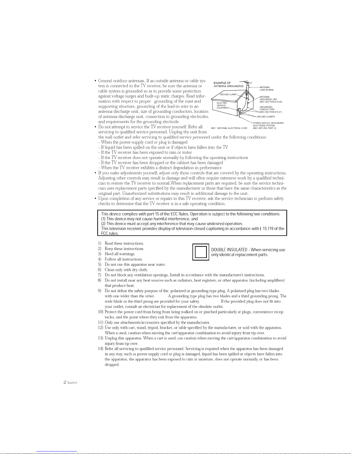
• Ground outdoor antennas. If an outside antenna or cable sys-
tem is connected to the TV receiver, be sure the antenna or
cable system is grounded so asto provide some protection
against voltage stages and built-up static charges. Read infGr-
marion with respect to proper grounding of the mast and
supporting structure, grounding of the lead-in wire to an
antenna discharge unit, size of grounding conductors, location
of antenna-discharge unit, connection to grounding electrodes,
and requirements ['or the grounding electrode.
• Do not attempt to service the TV receiver yourself. Refer all
servicing to qualified service personnel. Unplug the unit flora
EXAMPLE OF
ANTENNA GROUNDING
(NEC SECTION 810 20)
_POWER SERVICE GROUNDING
ELECTRODE SYSTEM
NEC NATIONAL ELECTRICAL CODE (NEC ART 250 PART H}
the wall outlet and refer servicing to qualified service personnel under the following conditions:
- When the powe>supply cord or plug is damaged
- Ifliquid has been spilled on the unit or if oI_ects have fallen into the TV
- If the TV receiver has been exposed to rain or water
- If the TV receiver does not operate normally by following the operating instructions
- If the TV receiver has been dropped or the cabinet has been damaged
- When the TV receiver exhibits a distinct degradation in performance
If you make adjustments yourself, adjust only those controls that are covered by the operating instructions.
Adjusting other conuols may result in damage and will often require extensive work by a qualified techni-
cian to restore the TV receiver to normal.When replacement parts are required, be sure the service techni-
cian uses replacement parts specified by the manufacturer or those that have the same characteristics as the
original part. Unauthorized substitutions may result in additional damage to the unit.
Upon completion of any service or repairs to this TV receiver, ask the service technician to perform safety
checks to determine that the TV receiver is in a safe operating condition.
This device complies with part 15 of the ECC Rules. Operation is subject to the following two conditions:
(1)This device may not cause harmful interference, and
(2)This device must accept any interference that may cause undesired operation.
This television receiver provides display of television closed captioning in accordance with _ 15.119 of the
FC¢ rules.
]) Readtheseinstructions.
2) Keeptheseinstructions. I_1 DOUBLEINSULATED- When servicing use
3) Heedall warnings, h_ only identical replacement parts.
4) Follow all instructions.
5) Do not use rids ai)params near water.
6) Clean only with dry cloth.
7) Do not block any ventilation openings, Install in accordance with the manufacturer's instructions.
8) Do not install near any heat sources such as radiators, heat registers, or other apparatus (including amplifiers)
that produce heat.
9) Do not deDat the saDty purpose of the polarized or grounding-type plug. A polarized plug has two blades
with one wider than the other. A grounding type plug has two blades and athird grounding prong. The
wide blade or the third prong are provided fbr your safeU: If the provided plug does not fit into
your outlet, consult an electrician fbr replacement of the obsolete outlet.
10) Protect the power cord fl'om being fl'om being walked on or pinched particularly at plugs, convenience recep-
tacles, and the point where they exit fl'om the apparatus.
11) Only use attachments/accessories specified by the manufi_cmrer.
12) Use only with cart, stand, tripod, bracket, or table specified by the manufacturer, or sold with the apparatus.
When a used, caution when moving the cart/api)aratus combination to avokl injury from tip-over.
13) Unplug this apparatus. When a cart is used, use caution when moving the cart/apparatus combination to avoid
injury fl'om tip over.
14) ReDr all servicing to qualified service personnel. Servicing is required when the apparatus has been dainaged
in any way,such as powe>supply cord or plug is damaged, liquid has been spilled or objects have fallen into
the apparatus, the apparatus has been exposed to rain or moisture, does not operate normally, or has been
dropped.
2 SAFETY
CONTENTS J
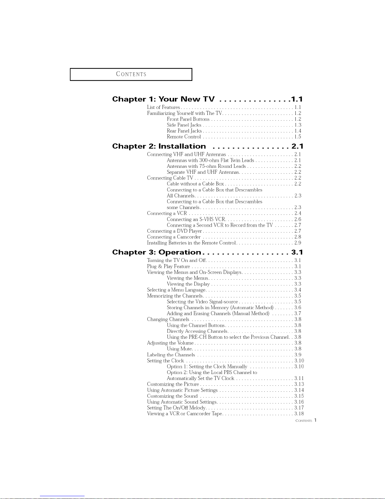
Chapter 1: Your New TV ............... 1.1
Lift of Features ......................................... 1.1
Familiarizing Yourself with The TV.......................... 1.2
From Panel Buttons .............................. 1.2
Side Panel Jacks ................................. 1.3
Rear Panel Jacks ................................. 1.4
Remote Control ................................. 1.5
Chapter 2: Installation ................ 2.1
Connecting VHF and UHF Antennas ........................ 2.1
Antetmas with 300-ohm Flat Twin Leads .............. 2.1
Antetmas with 75-ohm Round Leads ................. 2.2
SepaI-ate VHF and UHF Antennas .................... 2.2
Connecting Cable TV .................................... 2.2
CaNe without a CaNe Box ......................... 2.2
Connecting to a Cable Box that Descrambles
All Channels .................................... 2.3
Connecting to a Cable Box that Descrambles
some Channels .................................. 2.3
Connecting a VCR ...................................... 2.4
Connecting an 5-VHS VCR......................... 2.6
Connecting a Second VCR to Record fl'om the TV ....... 2.7
Connecting a DVD Player"................................. 2.7
Connecting a Camcorder ................................. 2.8
Installing Ba_teties in the Remote Control ..................... 2.9
Chapter 3: Operation .................. 3.1
Turning the TV On and (-)ft. ............................... 3.1
Plug & Play Feam_ ..................................... 3.1
Viewing the Menus and On-Screen Displays ................... 3.3
Viewing the Metros ............................... 3.3
Viewing the Display .............................. 3.3
Selecting a Menu Language ................................ 3.4
Memorizing the Channels ................................. 3.5
Selecting the Video Signal-source .................... 3.5
Storing Channels in Memolbv (Automatic Method) ....... 3.6
Adding and Erasing Channels (Mamlal Method) ........ 3.7
Changing Channels ..................................... 3.8
Using the Channel Buttons ......................... 3.8
Dil_ctly Accessing Channels ........................ 3.8
Using the PRE-CH Button to select the Ple_ious Channel.. 3.8
A@usting the Volume .................................... 3.8
Using Mute ..................................... 3.8
Labeling the Channels ................................... 3.9
Setting the Cbck ....................................... 3.10
(-)priori 1:Setting the Clock MamJally ................ 3.10
Option 2: Using the Local PBS Channel to
Automatically Set the TV Cbck ..................... 3.11
Customizing the Picml_ .................................. 3.13
Using Automatic Picmt_ Settings ........................... 3.14
Customizing the Sound .................................. 3.15
Using Automatic Sound Settings ............................ 3.16
Setting The On/Off Mebdy ................................ 3.17
Viewing a VCR or Camcorder Tape .......................... 3.18
coNr]N]_1
CONTENTS ]
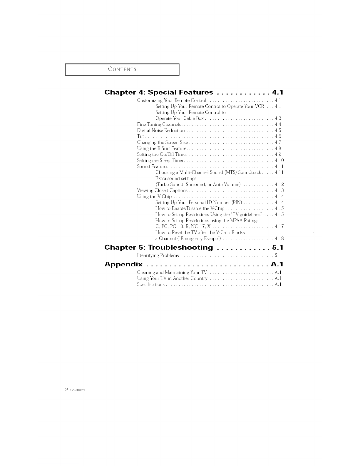
Chapter 4: Special Features ............ 4.1
Customizing Your Remote Control .......................... 4.1
Setting Up Your Remote Control to Operate Your VCR .... 4.1
Setting Up Your Remote Control to
Operate Your Cable Box ........................... 4.3
Fine • ruing Channels .................................... 4.4
Digital Noise Red*lction .................................. 4.5
Tilt .................................................. 4.(5
Changing the Screen Size ................................. 4.7
Using the R.S**rf Feat**re .................................. 4.8
Setting the On/Off Timer . ................................ 4.9
Setting the Sleep Timer. .................................. 4.10
Sound Features ......................................... 4.11
Choosing a M**lti-Channel Sol md (MTS) Solmdtrack ..... 4.1 1
Extra sound settings
(_*rbo Sound, Surround, or Auto Volume) ............ 4.12
Viewing Closed Captions ................................. 4.13
Using the VLChip ....................................... 4.14
Setting Up Yo**t"Personal ID Nt m_ber (PIN) ............ 4.14
How to Enable/Disable the V-Chip ................... 4.15
How to Set up Restrictions Using the "TV gtfidelines" . . . . 4.15
How to Set up Restrictions using the MPAA Ratings:
G, PG, PG-13, R, NC-17, X ........................ 4.17
How to Reset the TV after the V-Chip Blocks
a Channel ("Emergency Escape") .................... 4.18
Chapter 5: Troubleshooting ............ 5.1
Identif}/ing Problems .................................... 5.1
Appendix ........................... ,o,.1
Cleaning and Maintaining Yo**rTV .......................... A.1
Using Yo**t"TV in Another Col retry ............................
Specifications .......................................... A. 1
2 CON'[ _ N] S
Your NEw TV
List of Features
Your TV was designed with the latest technology This TV is a high-t_erformance unit that
inch*des the following special f_at*n'es:
• Easy-to-use remote control
• Easy-to-**se on-screen lrleI]* * systelrl
• Automatic timer to turn the TV on and off
• Ac{justable picture and sound settings that can be stored in the TV_ memoi T
• A**tomatic channel t, ruing for up to 181 channels
• A special filter to reduce or eliminate reception problems
• Fine t*ruing control for the sharpest pict* n'e possible
• Built-in, dual channel speakers
• A special sleep timer
• Headphone,jack fbr private listening
• 16:9 letter box format available depending upon sol*rce
CiiAp'rr, l/ (DNr,: YOIJ1,_ NFW TV 1 . ]
I
Your NEw TV
I
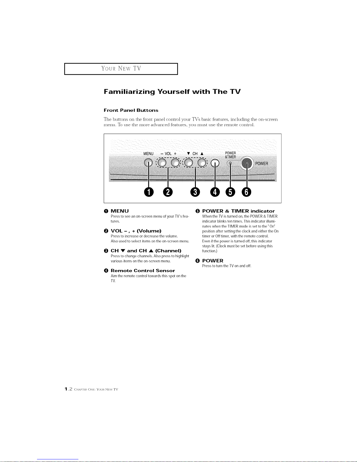
Familiarizing Yourself with The TV
Front Panel Buttons
The buttons on the front panel control your TV_ basic f_atures, including the on-screen
men.. To use the more advanced features, you must use the remote control.
O MENU O
Pressto see an on-screen menu of your TV's fea-
tures.
0
0
0
VOL - , + (Volume)
Pressto increase or decrease the volume.
Also usedto select items onthe on-screen menu.
OH !r and OH A (Channel)
Pressto change channels. Also pressto highlight
various items onthe on-screen menu.
Remote Control Sensor
Aim the remote control towards this spot on the
TV.
POWER & TIMER indicator
When the TV is turned on, the POWER& TIMER
indicator blinks ten times. This indicator illumi-
nates when the TIMER mode is setto the" On"
position aRer setting the clock and either the On
timer or Off timer, with the remote control.
Evenifthe power is turned off,this indicator
stays lit. (Clock must beset before using this
function.)
O POWER
Presstoturn theTVonandoff.
1.2 c ,A},-[]:_ON},:: YOUR N]:W TV
I Your NEW TV I
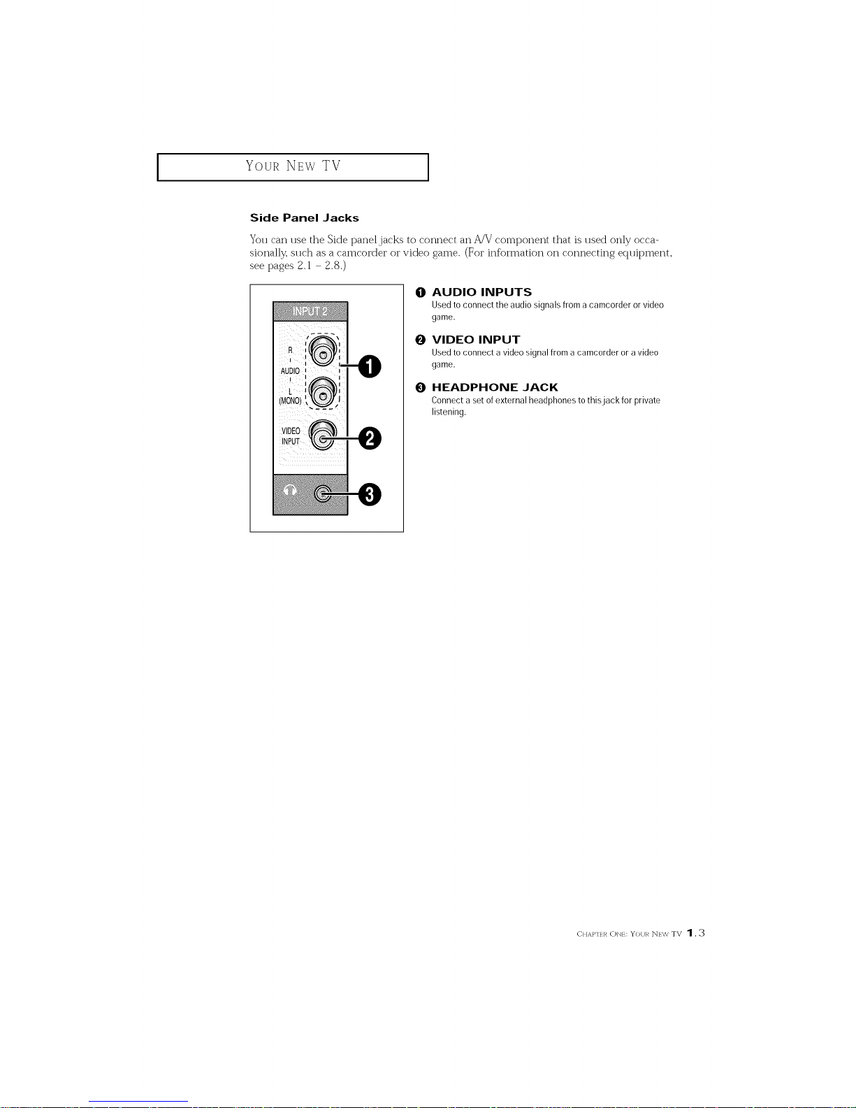
Side Panel Jacks
You can use the Side panel jacks to connect an A/V component that is used only occa-
sionally, such as a camcorder or video game. (For information on connecting equipment,
see pages 2. l 2.8.)
O AUDIO INPUTS
Used to connect the audio signals from a camcorder or video
game.
0 VIDEO INPUT
Used to connect a video signalfrom a camcorder or a video
game.
0 HEADPHONE JACK
Connect a set of external headphones to thisjack for private
listening.
CIIAPlr I/ ONr: YoI/1, _ NF\V TV 1.3
I
Your NEw TV
I
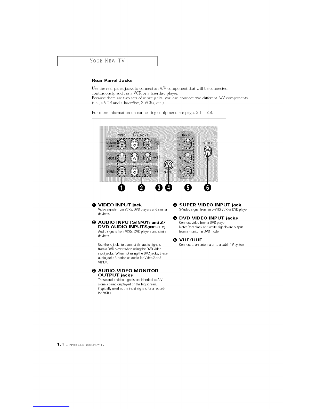
Rear PanelJacks
Use the rear panel,jacks to connect an AFV component that will be connected
contim 1011sly,sllch as a VCR or a laserdisc player.
Because there ai_ two sets of input jacks, you can connect two different A/V components
(i.e., a VCR and a laserdisc, 2 VCRs, etc.)
For more inftn'mation on connecting equipment, see pages 2.1 - 2.8.
@
O
O
VIDEO INPUT jack
Video signals from VCRs,DVD players and similar
devices.
AUDIO INPUTS(INPUT1 and 2)/
DVD AUDIO INPUTS(INPUT 2)
Audio signals from VCRs,DVD players and similar
devices.
Usethese jacks to connect the audio signals
from a DVD player when using the DVD video
inputjacks. When not using the DVDjacks, these
audio jacks function as audio for Video 2or S-
VIDEO.
AUDIO-VIDEO MONITOR
OUTPUT jacks
These audio-video signals are identical to A/V
signals being displayed on the big screen.
(Typicallyused as the input signals for arecord-
ing VCR.)
0 SUPER VIDEO INPUT jack
S-VideosignalfromanS-VHSVCRorDVDplayer.
O DVD VIDEO INPUT jacks
Connect video from a DVD player.
Note: Only black and white signals are output
from a monitor in DVD mode.
0 VHF/UHF
Connecttoanantennaortoa cableTVsystem.
1,4 c,A},-,:,, ONE: YOUR NEW TV
Your NEW TV
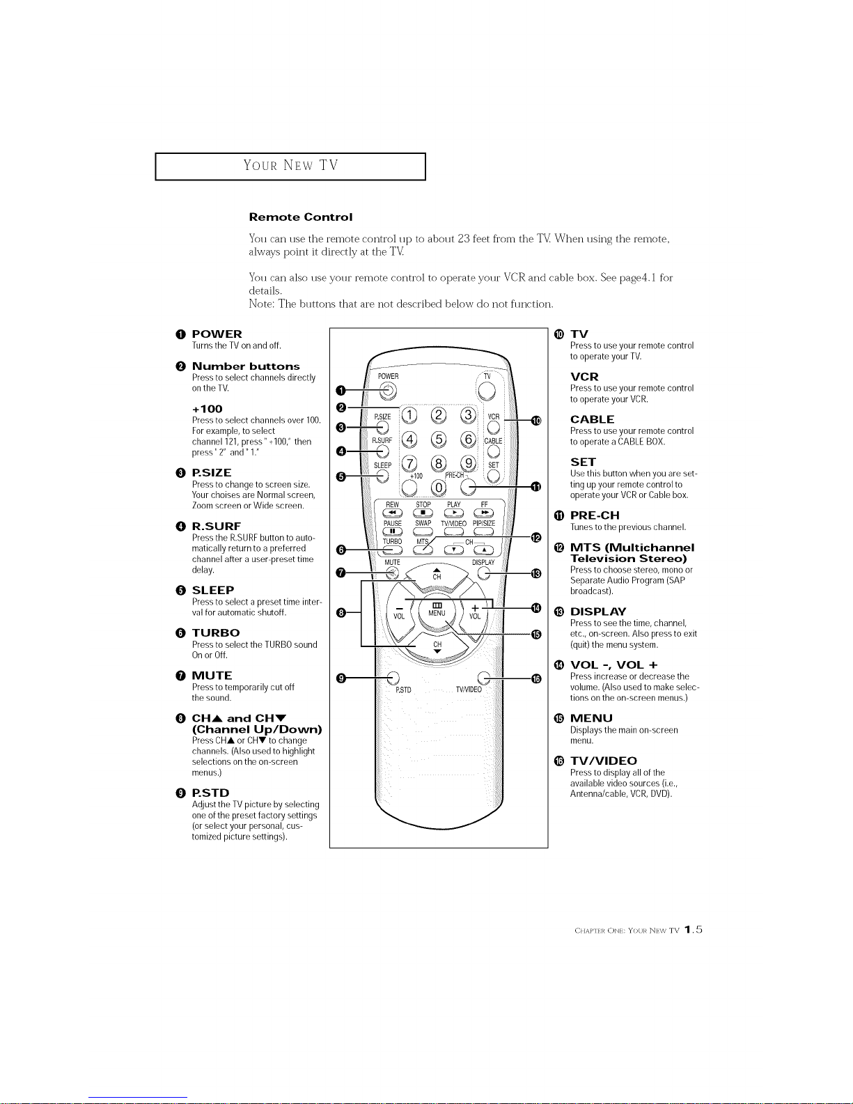
Remote Control
You can use the remote control up to about 23 feet from the TV_ When using the remote,
always point it directly at the TV_
You can also use your remote control to operate your VCR and cable box. See page4.1 for
details.
Note: The buttons that are not described below do not fm_ction.
0 POWER
Turnsthe TVonand off.
0 Number buttons
Press to select channels directly
onthe TV.
+100
Press to select channels over 100.
For example, to select
channel 121,press" +100,"then
press" 2" and" 17
e P.SlZE
Press to change to screen size.
Yourchoises are Normal screen,
Zoomscreen or Wide screen.
0 R.SURF
Press the R.SURFbutton to auto-
matically return to a preferred
channel after a user-preset time
delay.
0 SLEEP
Press to select a preset time inter-
val for automatic shutoff.
O TURBO
Press to select the TURBOsound
On or Off.
O MUTE
Pressto temporarily cut off
the sound.
0 CHA and CHV
(Channel Up/Down)
Press CHA orCHV to change
channels. (Also used to highlight
selections on the on-screen
menus.)
O P.STD
Adjust the TV picture by selecting
one ofthe preset factory settings
(or select your personal, cus-
tomized picture settings).
ii:ili!_
@
@
e
e
@
@
O
TV
Pressto useyour remote control
to operate your TV.
VCR
Pressto useyour remote control
to operate your VCR.
CABLE
Pressto useyour remote control
to operate a CABLEBOX.
SET
Use this button when you are set-
ting up your remote control to
operate your VCR or Cable box.
PRE-CH
Tunesto the previous channel.
MTS (Multichannel
Television Stereo)
Pressto choose stereo, mono or
Separate Audio Program (SAP
broadcast).
DISPLAY
Pressto seethe time, channel,
etc., on-screen. Also press to exit
(quit) the menu system.
VOL -, VOL +
Press increase or decrease the
volume. (Also used to make selec-
tions on the on-screen menus.)
MENU
Displays the main on-screen
menu.
TV/VlDEO
Pressto display all of the
available video sources (i.e.,
Antenna/cable, VCR,DVD).
CHAPlr l/ C)Nr: YoI/1, _NF\': TV 1.5
I
Your NEw TV
I
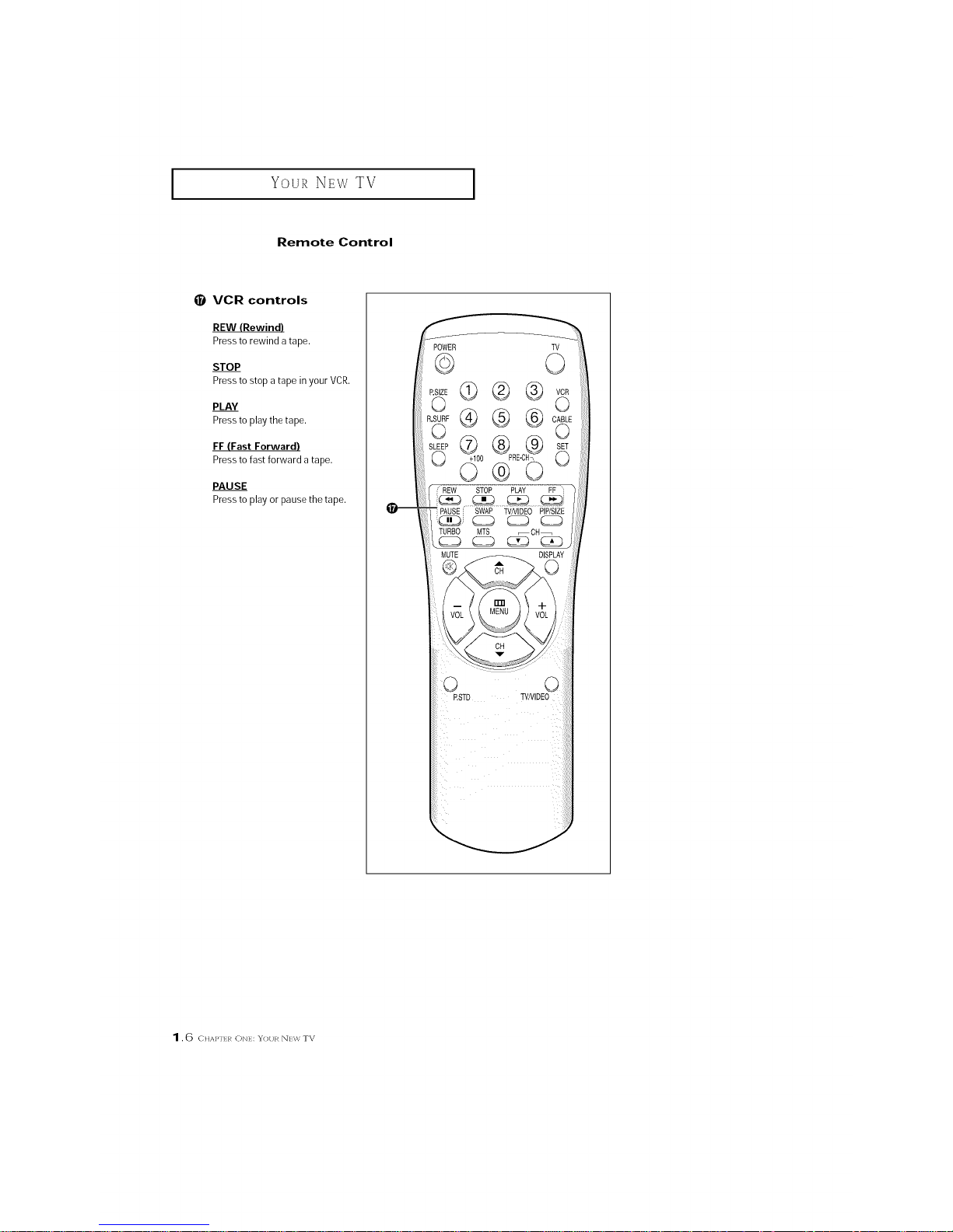
Remote Control
VCR controls
REW (Rewind)
Pressto rewind a tape.
STOP
Pressto stop a tape in your VCR.
PLAY
Pressto playthe tape.
FF (Fast Forward)
Pressto fast forward a tape.
PAUSE
Pressto play or pause the tape.
POWER
©
TV
0
¢®®
®®®
G¢
+100
O®
STOP PLAY FF i
PAUSE_ SWAP TVNIDEO PIP/SIZE
TURBO MTS _CH_
DISPLAY
CH
CH
P.STD
1.6 C,AI"H:,_ON},::YOUR N]:\,'/_ TV
INSTALLATION
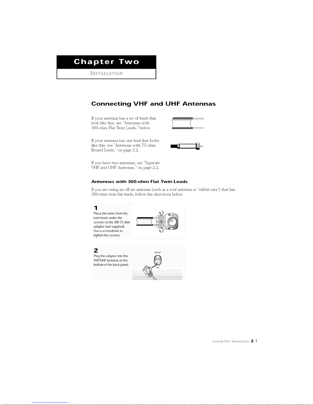
Connecting VHF and UHF Antennas
If yolu" antenna has a set of leads that
look like this, see "Antennas with
300-ohm Flat Twin Leads," below.
If yolu" antenna has one lead that looks
like this, see "Antennas with 75-ohm
Round Leads," on page 2.2.
If you have two antennas, see "%parate
VHF and UHF Antennas," on page 2.2.
Antennas with 300-ohm Flat Twin Leads
If"you are using an off-air antenna (sllch as a roof antenna or "rabbit ears") that has
300-ohm twin flat leads, fbllow the directions below.
Place the wires from the
twin leads under the
screws onthe 300,75ohm
adaptor (not supplied).
Use a screwdriver to
tighten the sc[ews.
'_ VHF/_JHF
Plugthe adaptor into the _-_
VHFIUHFterrr hal onthe
bottom of the back panel
CHAI"[H_ TWO: ]NS'IAI IA'I]ON 2,1
INSTALLATION
I
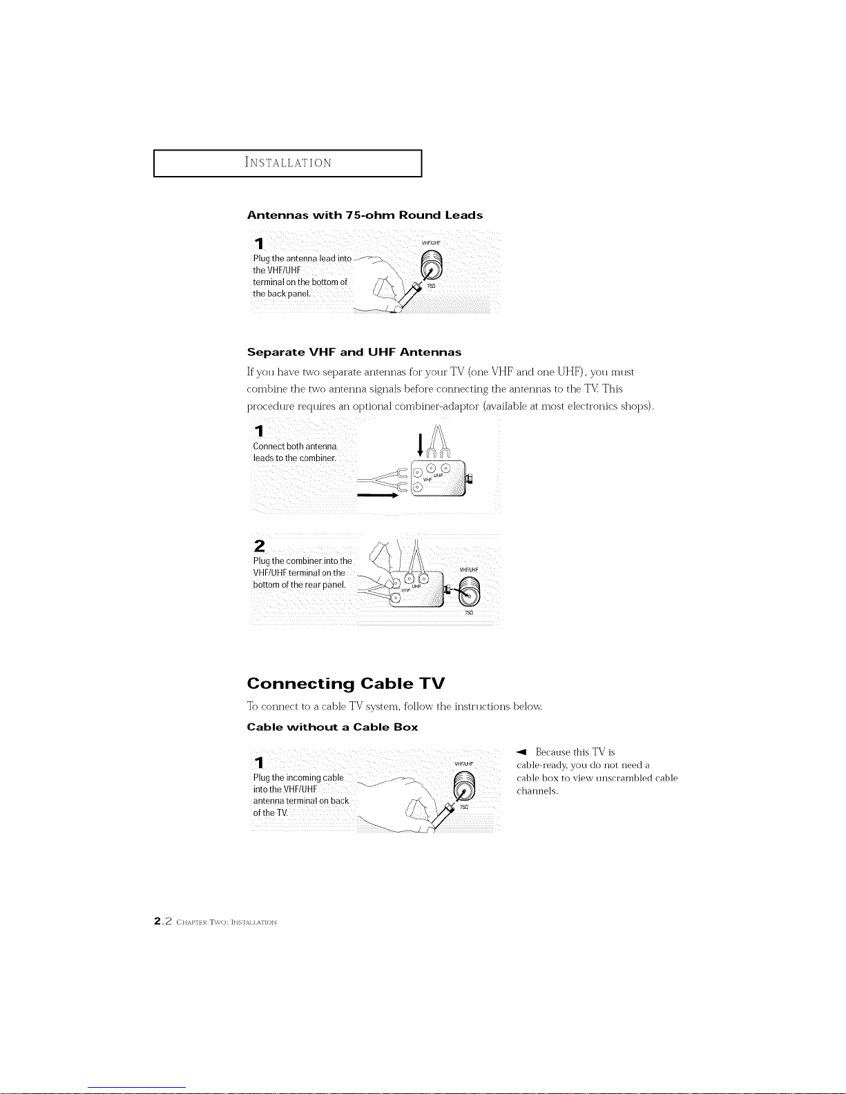
Antennas with 75-ohm Round Leads
plug the antenna !ead into _
theVHF!UHF \
terminal on the bottom of
the back pane!.
Separate VHF and UHF Antennas
If you have two separate antennas for yo]]r TV (one VHF and one UHF), you m]]st
combine the two antenna signals before connecting the antennas to the TV This
procedure reqtfires an optional combiner-adaptor (available at most electronics shops).
Connect both antenna
leads to the combiner.
i g C0mbinerint0the <\_ !//_\
VHF!UHFtermina! 0nthe _._ _.._ ....._ VHF/UHF
bottomoftberearp nel.
Connecting Cable TV
To connect to a cable TV system, follow the insti'Hctions below.
Cable without a Cable Box
Plugthe incoming cable _ _-_\
into the VHF!UHF "_J
antenna terminal on back
75_
ofthe TV.
Because this TV is
cable-ready, you do not need a
cable box to view unscrambled cable
channels.
2,2 CHAP'I; l/ TWO: ]NS'fAI1 ATION
I
INSTALLATION
I
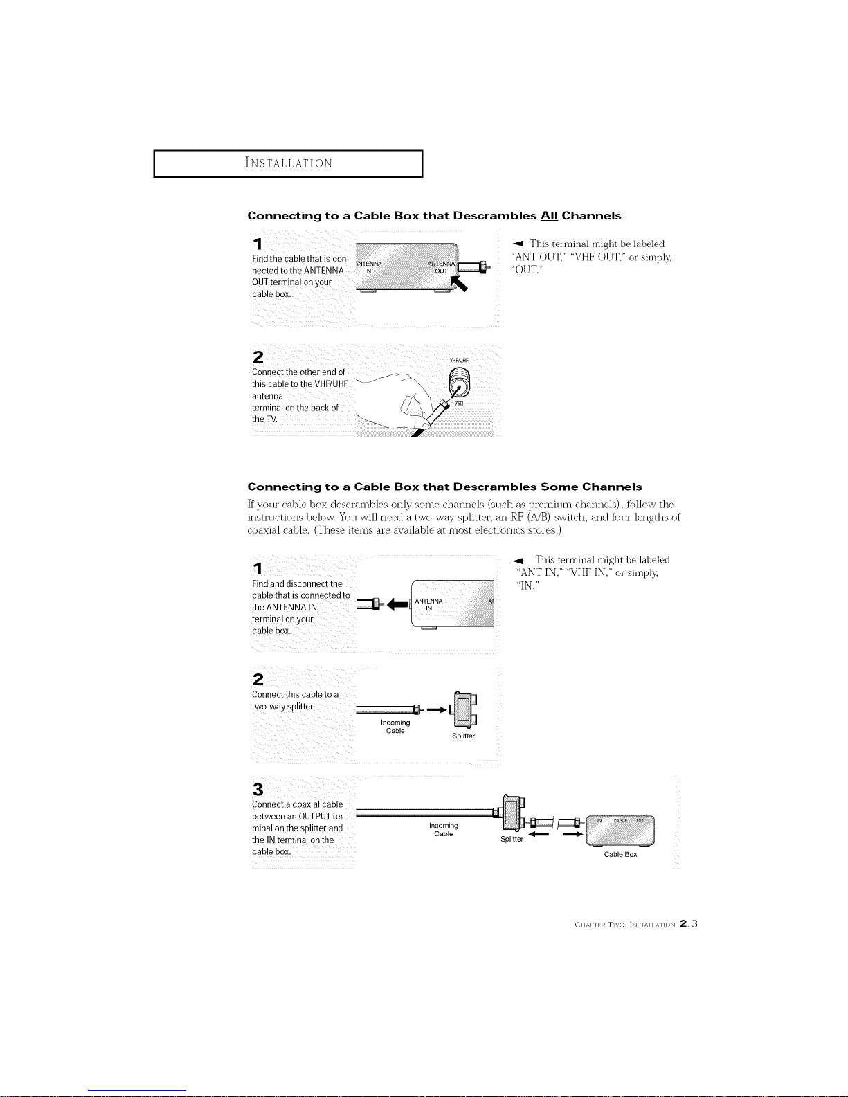
Connecting to a Cable Box that Descrambles AI__IChannels
"_ This terminal might be labeled
"ANT OUT," "VHF OUT," or simply,
"OUT."
cable box,
2 ¸ ) :) _._/_.F
Connect the Otherend of i..
this Cableto the VHF/UHF ""J/'_"\.\
antenna
terminal on the back of
the TV.
Connecting to a Cable Box that Descrambles Some Channels
If yottr cable box descrambles only some channels (sttch as premittm channels), follow the
instrttctions below. Yott will need a two-way splitter, an RF (A/B) switch, and fbttr lengths of
coaxial cable. (These items are available at most electronics stores.)
Findand disconnect the
cable that is co_nected to
the ANTENNA N
terminal onyour
cable BOX.
S_ E[[er
_1 This terminal might be labeled
"ANTIN," "VHFIN," or sin-lply,
"IN."
2
Connec[ this cabte to a
[wo-way spH[[er
incoming
Cable
Connect a coaxial CaBle
Be[ween an OUTPU] ter-
minal onthe splitter anti
the IN termiqa on the
cable box.
ncomlng
CaBle
Splitter
Cable Box
CHAP'[H_ TWO: ]NSqAIIA'HON 2, :_
INSTALLATION
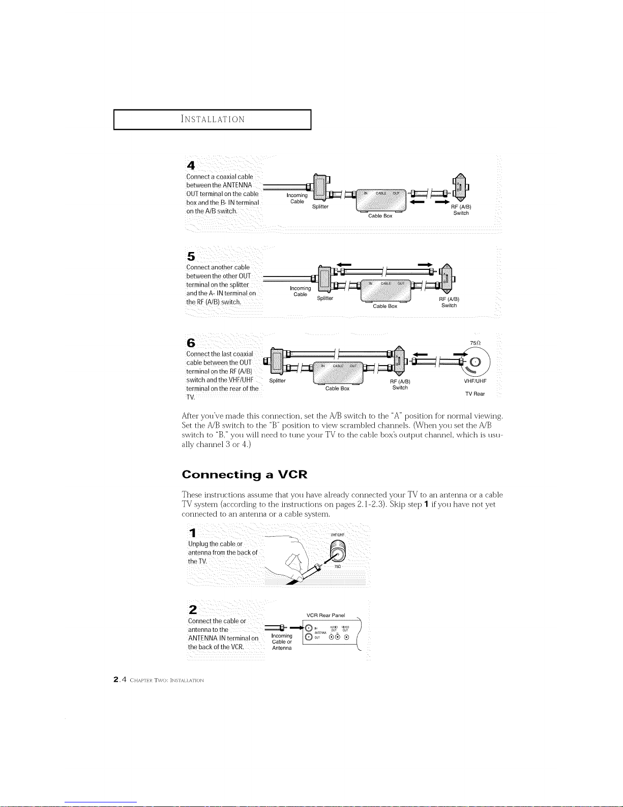
Connect a coaxial cable
between the ANTENNA .......................................
OU1 terminal onthe cable Incomin
box and the B=INterminal Cable
on the AiB switch. SpliCer
Cable Box Switch
Connect another cable
between the other OUT
terminal on the splitter Incoming
and the A- IN terminal on Cable
the RF(A/B) Switch, Splitter RF(A/B)
CableBox Switch
Connect the last coaxial
cable between the 0
termina! on the RE(AIB)
switch and the VHF/UHF Splitter
terminal on the rear of the
TV.
Cable Box
75_
RF (A/B) VHF/UHF
Switch
TV Rear
After you've made this connection, set the A/B switch to the "A" position %r normal viewing.
Set the A/B switch to the "B" position to view scrambled channels. (When you set the A/B
switch to "B," yott will need to tttne yottr TV to the cable box_ otttpttt channel, which is ttstt-
ally channel 3 or 4.)
Connecting a VCR
These instrttctions asstnne that yott have ah'eady connected yottr TV to an antenna or a cable
TV system (according to the insti'ttctions on pages 2.1-2.3). Skip step 1 if yott have not yet
connected to an antenna or a cable system.
Unplug the cable or -_
antenna from the back of
7s_
VCR Rear Panel
Connect the cable or
--IS....
ANTENNA IN terminal on Incoming , _E_A (_(_ Q
Cable or
the back ofthe VCR. Antenna
2.4 c.Ap..,_Two: IN%fAI1ATION
INSTALLATION
I
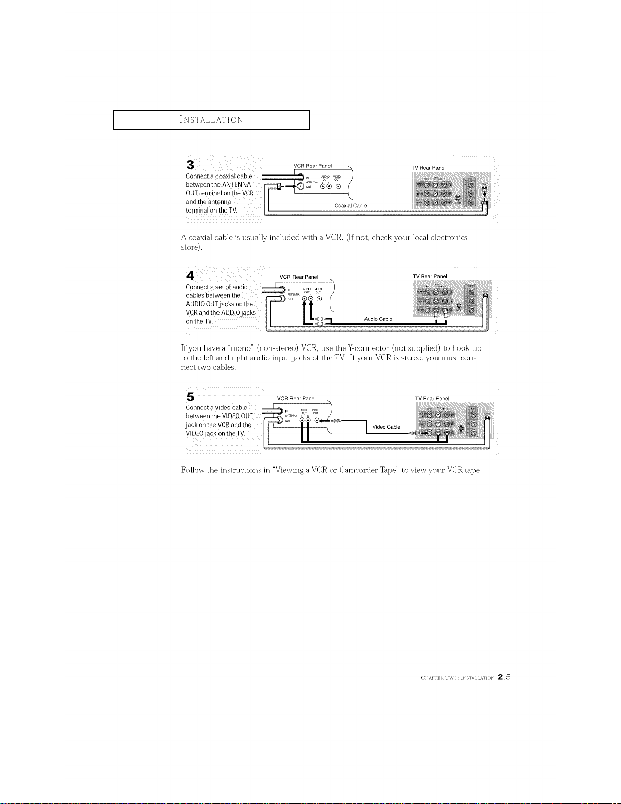
VCR Rear Panel
Connect a coaxial cable )
(
between the ANTENNA
OUT terminal onthe VCR
and the antenna CoaxialCable
terminal on the TV,
TV Rear Panel
A coaxial cable is usually included with a VCR. (If not, check your local electronics
st oi'e).
Connect a set of audio
cables between the
AUDIO OUTjacks on the
VCRand the AUDIOjacks
on the TV.
Audio Cable
TV Rear Panel
If you have a "mono" (non-stereo) VCR, use the Y-connector (not sut_pliecl ) to hook up
to the left and right audio ii-q_ut jacks of the TV_ If your VCR is stereo, you must coi'_-
nect two cables.
5
Connect a video cable
between the VIDEOOUT
jack on the VCRand the
V!DE0jack 0nthe TV,
VCR Rear Panel TV Rear Panel
Video Cable
Follow the instructions in "Viewing a VCR or Camcorder Tape" to view your VCR tape.
_-}}]AP'[_R TWO: ]NS'IAIIA'I]ON 2,5
INSTALLATION
I
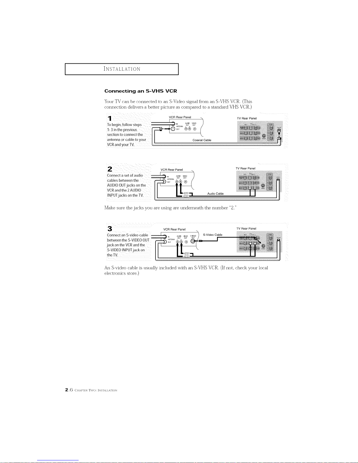
Connecting an S-VHS VCR
Your TV can be connected to an S-Video signal from an S-VHS VCR. (This
connection delivers a better picture as colnt_ared to a standard VHS VCR.)
VCR Rear Panel
To begin, f011owsteps _" o_T o_-
1- 3 inthe previous i_E,,, (_ ®
section to connect the
antenna or cable to } Coaxial Cable
VCRandy0ur Tv.
TV Rear Panel
Connect a set Ofaudio
cables between the
AUDIO OUTjacks onthe
VCRandthe 2 AUDIO
INPUTjacks on the TV.
VCR Rear Panel
Audio Cable
TV Rear Panel
Make sure the jacks you are using are ui_dei'i_eath the number "2."
VCR Rear Panel TV Rear Panel
Connect an S:video cab S-VideoCable
between the S-VIDEOOUT
jack onthe VCRand the
S_VIDE0INPUTjack 0n
the TV.
An S-video cable is usually included with an S-VHS VCR. (If not, check your local
electronics store.)
2.6 c}iAp,.1_Two: ]N%fAI] ATION
 Loading...