


Samsung CF21M Alignment and Adjustments

4 Alignment and Adjustments
This section of the service manual explains how to make permanent adjustments to the monitor.
4-1 Adjustment Conditions
Caution: Changes made without the Softjig are saved only to the user mode settings. As such, the
settings are not permanently stored and may be inadvertently deleted by the user.
4-1-1 Before Making Adjustments
4-1-1 (a) ORIENTATION
When servicing, always face the monitor to the
east.
4-1-1 (b) WARM-UP TIME
The monitor must be on for 30 minutes before
starting alignment. Warm-up time is especially
critical in color temperature and white balance
adjustments.
4-1-1 (c) SIGNAL
Analog, 0.7 Vp-p positive at 75 ohm, internal
termination
Sync: Separate/Composite
(TTL level negative/positive)
Sync-on-Green:
Composite sync 0.3 Vp-p negative
(Video 0.7 Vp-p positive)
4-1-1 (d) SCANNING FREQUENCY
Horizontal: 30 kHz ~ 115 kHz (Automatic)
Vertical: 50 Hz ~ 160 Hz (Automatic)
Unless otherwise specified, adjust at the
1280 x 1024 mode (H: 91 kHz, V: 85 Hz) signals.
Refer to Table 2-1 on pages 2-2 and 2-3.
4-1-1 (e) HIGH VOLTAGE ADJUSTMENT
Signal: 1280 x 1024 mode (91 kHz/85 Hz)
Display image: Full white
Contrast: Maximum
Brightness: Maximum
Limit: 27.5 kV ± 0.5 kV
Measure the hight voltage level at the anode cap.
High voltage should be within the limit as above.
4-1-1 (f) G2 (SCREEN) VOLTAGE
The Screen Voltage is fixed in the firm so don’t
need to adjust the Screen voltage.
4-1-1 (g) CENTER RASTER
Adjust VR401 so that the back raster comes to the
center when you apply a signal of 91 kHz/85 Hz.
4-1-2 Required Equipment
The following equipment may be necessary for
adjustment procedures:
4-1-2 (a) DISPLAY CONTROL ADJUSTMENT
1. Non-metallic (–) screwdriver: 1.5 mm
Non-metallic (–) screwdriver: 3 mm
2. Philips (+) screwdriver: 1.5 mm
3. Non-metallic hexkey: 2.5 mm
4. Digital Multimeter (DMM), or
Digital Voltmeter (DVM)
5. Signal generator, or
Computer with a video board that uses the
ET-4000 chipset (strongly recommended if
using Samsung DM 200 software) and that
displays: 1280 x 1024 @ 85 Hz, or 1600 x 1200
@ 85 Hz (maximum).
6. Personal computer
4-1-2 (b) COLOR ADJUSTMENTS
1. All equipment listed in 4-1-2 (a), above
2. Color analyzer, or any luminance
measurement equipmen
4-1-3 After Making Adjustments
After finishing all adjustments, test the monitor in
all directions. If, for example, the monitor does not
meet adjustment specifications when facing north,
reposition the monitor to face east and readjust.
This time, try for an adjustment closer to the ideal
setting within the tolerance range. Test the unit
again in all directions. If the monitor again fails to
meet specifications in every direction, contact
your Regional After Service Center for possible
CRT replacement.
CF21M* 4-1
4 Alignment and Adjustments
4-2 Display Control Adjustments
4-2-1 Centering
Centering means to position the center point of
the display in the middle of the display area.
Horizontal size and position and vertical size and
position control the centering of the display.
Adjust the horizontal size and vertical size to their
optimal settings: 312 mm (H) x 234 mm (V).
1280 x 1024 mode (91 kHz/85Hz)
Adjust the horizontal position and vertical
position to ≤ 4.0 mm of the center point of the
screen.
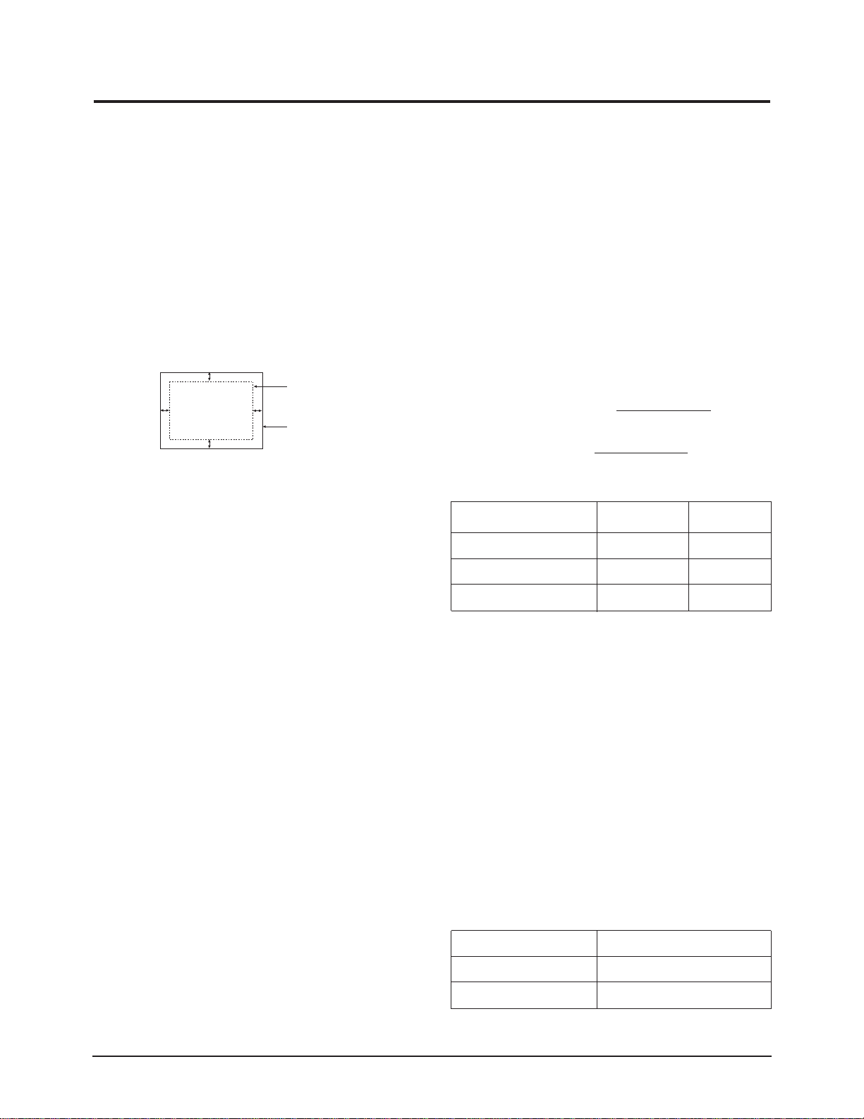
|A-B| ≤ 4.0 mm. |C-D| ≤ 4.0 mm.
C
DISPLAY AREA
A
D
Figure 4-3. Centering
4-2-1 (a) HORIZONTAL SIZE ADJUSTMENT
CONDITIONS
Scanning frequency: 91 kHz / 85 Hz
Display image: Crosshatch pattern
Brightness: Cut-off
Contrast: Maximum
Click on the << or >> box next to SIZE B+ to
adjust the horizontal size of the display pattern
to 312 mm (Tolerance: ± 3 mm) as the “H_SIZE”
is “62” on the OSD.
4-2-1 (b) VERTICAL SIZE ADJUSTMENT
CONDITIONS
Scanning frequency: 91 kHz /85 Hz
Display image: Crosshatch pattern
Brightness: Cut-off
Contrast: Maximum
Click on the << or >> box next to V_SIZE to
adjust the vertical size of the display pattern to
234 mm. (Tolerance: ± 3 mm.)
4-2-1 (c) HORIZONTAL POSITION ADJUSTMENT
CONDITIONS
Scanning frequency: 91 kHz / 85 Hz
Display image: Crosshatch pattern
Brightness: Cut-off
Contrast: Maximum
Click on the << or >> box next to H_POSI to
center the horizontal image on the raster.
B
EDGE OF BEZEL
4-2-1 (d) VERTICAL POSITION ADJUSTMENT
CONDITIONS
Scanning frequency: 91 kHz / 85 Hz
Display image: Crosshatch pattern
Brightness: Cut-off
Contrast: Maximum
Click on the << or >> box next to V_POSI to
center the vertical image on the raster.
4-2-2 Linearity
Linearity affects the symmetry of images as they
appear on the screen. Unless each row or column
of blocks in a crosshatch pattern is of equal size,
or within the tolerances shown in Table 4-1 an
image appears distorted, elongated or squashed.
Horizontal Linearity = 2x x100
Vertical Linearity = 2x x100
Preset mode
Pre-load mode (48kHz~) ≤ 5% ≤ 10%
Pre-load mode (under 48kHz) ≤ 5% ≤ 14%
❈ Preset Mode : 91 KHz / 85 Hz
Pre-load Mode : Refer to Timing Chart
4-2-2 (a) HORIZONTAL LINEARITY ADJUSTMENT
CONDITIONS
Scanning frequency: 91 kHz / 85 Hz
Display image: Crosshatch pattern
Brightness: Cut-off
Contrast: Maximum
To adjust the Horizontal Linearity, refer to Table
4-1 for the tolerance range.
Click on the << or >> box next to H_LIN to
optimize the image.
(Horizontal x Vertical Size Table)
Horizantal 393
Vertical 294.5
X max-X min
X max+X min
Y max-Y min
Y max+Y min
Table 4-1
Adjacent Linearity
≤ 4% ≤ 8%
Table 4-2
Entire Linearity
21”
4-2 CF21M*